1
General Instructions
2
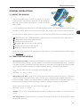
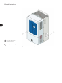
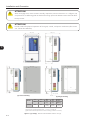
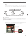
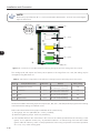
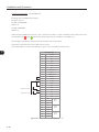
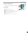
M
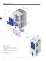
Inverter with Nema1 kit
(optional)
A – Keypad
B – Control rack cover
C – CC11 control board
D – FLASH memory module
E – Control accessory module (refer to the section 7.2)
F – Anybus-CC accessory module (refer to the section 7.2)
G – Bottom front cover
H – Heatsink fan
I – Mounting supports (for through the wall mounting)
J – Hoisting eye
K – Rear part of the inverter (external part for flange mounting)
L – SRB2 Safety stop board
M – Nema1 kit top cover (“hat”)
N – Nema1 kit bottom (Conduit kit)
N
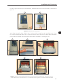
Figure 2.2 - Main components of the CFW-11
2-6