1
DS4-2156
Remote Space Optical Transfer Unit
SOT-CP1601/16 03 series
Compatible with CC-Link Ver. 1.10
Operation Manual
R ead thi s manu al before u se.
● Thoroughly read this manual and understand its contents before using,
inspecting or servicing this unit.
Toyo Elec tric co. Ltd.,
Electronics Division
Hea d O ff i ce/
H iki zawa 1-39, K agiya-cho, Kasugai , Ai chi 480-0393
Kagi ya Fact ory
P hone: 05 68-8 8-11 81
Tokyo
F urukaw a Chi yoda B uil di ng N o. 95, Uchi kanda 2 -15-9, Chi yoda-ku,
Sal es Of fi ce
Fax: 0568-88-3086
T okyo 101 -004 7
P hone: 03 -325 6-66 65
Fax: 03-3254-3650
Nag oya
H anagurum a So uth Bui l ding No. 901, M eie ki 5-1 6-17 , Nakam ura-ku ,
Sal es Of fi ce
N agoya 450-0002
P hone: 05 2-58 1-85 08
Fax: 052-582-2020
Osaka
O saka Godo Bui ldi ng No. 8 01, Doyam a-cho 1-5, Ki ta-ku,
Sal es Of fi ce
O saka 530-0027
P hone: 06 -636 1-16 26Fax: 06-6312-6762
Hi roshim a
Sal es Of fi ce
K N Bui ldi ng No. 201 , Osu 3-7-2 , Mi nam i-ku, H iroshi ma,
H iroshi ma 732-0802
P hone: 08 2-28 5-61 94
Fax: 082-285-7286
DS 42107A. j td 2000. 09. 05
- 1 -
DS4-2156
I nt rod ucti on
● Thank you for choosin g our SOT-CP 1601/ 1603 seri es re mot e sp ace opt i cal t ra nsfer unit .
● Ful ly underst and t he cont ent s of thi s m anual before st art i ng t he in stal la ti on or
mai nt enance work.
● I f you have a ny quest i on o r need f urt her inf ormat i on regardi ng t hi s m anual , consul t t he
nearest sal es o ff i ce or the Sal es Engi neering Sect i on, El ect roni cs Di vi si on, Kagi ya
Fact ory at 0 568-88-1 181.
● Keep t his man ual wi t h care.
Ou tl ine
● These series provide remot e space opti cal t ransf er uni ts com pati bl e w it h the M it subi shi
El ectri c's PLC `CC-Li nk V er. 1.1 0' (he rei naf te r, ref erred t o as C rem ote SO Ts).
● The C rem ot e S OT is a rem ot e I / O unit where a si ngl e st at ion can be occupie d by a
syste m.
● Up t o 64 C remot e SOTs can be connect ed w it h a si ngl e m ast er uni t.
● I t is a parall el opt i ca l transf er u nit w it h 16 input bit s and 16 out put bit s.
● The SOT-CP 1601 seri es cannot com mun icat e wit h t he S OT-4102H3 and SO T-V 1601R
series.
● The SOT-CP 1603 seri es cannot com mun icat e wit h t he S OT-4302H3 and SO T-V 1603R
series.
The names of syst em s, product , comp anies, etc. shown i n t hi s m anual are tradem arks of
relevant compa nies.
● The model s compat i ble wi t h t he CC -Li nk, Ve r. 1.10
are
marked wi t h t he logo show n t o th e rig ht.
● The C rem ot e S OT is marked wi t h t he logo on t he na mepl at e at th e rear of th e m ain body.
- 2 -
DS4-2156
Con tents
1. Precaut ionary Notes
………………………………………………… 4
2. Const ruct ion
……………………………………………………………… 5
2-1. Model
5
2-2. Example of wiring
5
2-3. Applicable master/local units
5
3. Component Names and Functions
………………………… 6
4. Settings and Procedure
…………………………………………… 7
4-1. Procedure
7
4-2. Switch settings
8
4-3. Description of Modes
10
4-4. Installation
11
5. Electric Connection
5-1. Connection diagram
5-2. Caution in wiring
6. Programming Procedure
………………………………………………… 12
12
14
…………………………………………… 15
6-1. Out line of dat a exchange
6-2. Master station input/output signals
6-3. Master station buf fer memory
6-4. Data processing time
6-5. Programming
7. Trouleshooting
15
17
18
23
24
……………………………………………………… 27
7-1. In case a problem occurs
7-2. Troubleshooting
27
28
8. Maint enance and I nspection
…………………………………… 32
9. Specifications
………………………………………………………… 33
9-1. CC-Link specif ications
33
9-2. Opt ical transfer specificat ions
10. Schematic
33
……………………………………………………………… 34
11. Gurant ees
…………………………………………………………… 35
12. Revision History
…………………………………………………… 35
- 3 -
DS4-2156
1. Pre cauti onary Not es
1-1. Pow er suppl y
Use a regu lat ed volt age ( 24 VDC ) p ower sup ply t hat me ets t he spe cif icat i ons f or thi s u nit .
1-2. Re sett i ng t i me
The unit does not f unct ion f or about a m i nute af t er pow er-up as t he i nternal reset t ing ci rcui t
is act ivat ed during t his perio d.
1-3. Op erat i on mode sel ecti on ( i n M/ S mode )
The parall el opt i cal transf er u nit sh ould be in t he mast er m ode when th e ot her one i s in t he
slave m ode o r vice versa. The uni t has been f actory-set t o t he ma ster mode. To ch ange
t he ope rat i on m ode t o sl ave, t urn t he mod e sel ect sw it ch ( S W1 ) at the t op of t he mai n bo dy
on.
1-4. Ca uti on in i nstal l ati on
Use t his uni t ind oor. Do not use i t where:
① th ere m ay be dust , suspend ed part icl es or wa ter or oi l spla shes t hat w il l dam p o pti cal
si gnal s,
② an evaporated sol vent or corrosi ve g as exi sts,
③ a l i ght cont ai ning m uch i nf rared rays such as sunli ght o r inca ndescent l ig ht ( di st urbi ng
l ight ) di rectl y e nters the proj ecto r/ receiver,
④ th e uni t m ay b e expose d t o a t em pera ture, h umi dit y, vi brati on or i mpact th at exceeds th e
rat ing,
⑤ th e SO T's opt ical passage may be i nt errup ted by a pe rson or a noth er obst acle, or
⑥ a d evice t hat wi l l generat e a st rong m agnet ic f iel d ( e .g. elect romag neti c conta ctor or
m oto r ) or a source of radi o f requenci es ( e. g. invert er ) i s used.
1-5. Ext ent io n of the cabl e
The dat a l in k and powe r cabl es shou ld be separatel y exten ded.
① Powe r cabl e speci f icat i ons
0. 3 mm 3 o r more. T he cab le shoul d be as short as possibl e and m ust not exceed 50 m .
I nst all a regul at ed vol t age p ower sup ply wi th in 50 m. Th e ext ensi on sh ould be adj usted
i n con siderat ion of volt age drop. A shie lded pow er cabl e i s recom men ded.
② Dat a li nk cab le
Spe cif ied by t he bau d rat e, et c. Se e sect i on 5 `Ele ctri c Co nnecti on. '
Use a data l ink cabl e ded icat ed fo r CC -Li nk.
Mast er/ Local Uni t s.
For det ail , see t he U ser' s M anual f or CC-Li nk
1-6.Th e f ol low ing i nstruct ion s shoul d be ob served i n rout i ng t he dat a l i nk and pow er cabl es t o
prote ct th em from no ises and surge s.
① They should be separat ely wi red and m ust not b e l ai d near or bund led t oget her wi t h t he
m ain ci rcui t or any l in e w it h a hi gh volt age or l oad ( shoul d be at l east 1 00 m m away f rom
t hem ) .
② The same appl ies t o cab le re lays.
1-7.C omm uni ca ti on sett i ngs
Thi s uni t requi re s several i t ems to be set w it h sw it ches, i ncl udin g t he stat i on No. and baud
rate. See 4-2 `Swi t ch set t in gs.'
1-8. Termi nal resi sto rs
A term inal resi st or provid ed w it h the m aster/ slave uni t shoul d be i nst all ed at each end of
t he dat a li nk cable .
1-9. 16t h inpu t/ out put bi t s
The 16t h i nput ( I N ) bi t ha s been f act ory-set t o CTL and th e 16t h out put ( O UT ) bi t t o R CV.
Wh en usi ng th e 16t h inp ut/ out put b it s f or co ntrol i nput s/o utpu ts, set mod e sel ect sw it ch S W3
t o O N.
- 4 -
DS4-2156
2. Const ru cti on
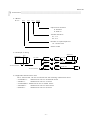
2-1.M odel
SOT− CP
16
01
Opt ical axis direct io n
H : He ad-o n
S : Si de-on
Tran sfer dist ance
0 1: 1 m
0 3: 3 m
Numb er of i nput / out put bi ts
1 6: 16 bit s each
Series mode l
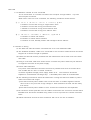
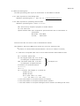
2-2.E xampl e o f wi ri ng
Sequencer
Sequencer
Mast er
uni t
CPU
CPU
CC-Link
SO T-CP
160 1
SOT -CP
CC-Link
1 601
T erminal resistor
SO T-CP
160 1
SOT -NP
Parallel I/ O
Te rmi nal resi stor
1 601
Terminal resistor
Terminal resist or
SO T-CP
SOT -NP
1601
1601
Parallel I/ O
2-3.A ppli cabl e m ast er/ l ocal uni ts
The C rem ot e S OT can b e conne cted wi t h t he fo ll owi ng mast er/l ocal uni t s.
・ A1SJ61B T11:
M ast er/ l ocal uni t f or An S/A 2US series
・ AJ61BT1 1:
M ast er/ l ocal uni t f or A series
・ A1SJ61Q BT11: Mast er/l ocal uni t f or Q 2AS series
・ AJ61Q BT11:
M ast er/ l ocal uni t f or Q nA se ri es
・ QJ61B T11:
M ast er/ l ocal uni t f or Q serie s
- 5 -
I/ O
DS4-2156
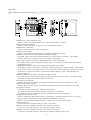
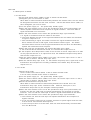
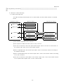
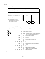
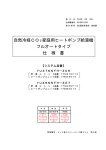
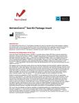
3. Comp onent N ames and Funct ions
( Side on )
( Head on )
① St ati on No. select swit ches ( x2 )
U se d t o select the remo te st ati on No. o f t he un it be tw een 1 and 64.
② Baud rate sel ect swi t ch
U se d t o select the baud rat e of the CC -Link bet ween 0 and 4.
③ Mode sel ect swi t ches
U se d t o select the M /S m ode, X mo de, et c.
④ POW ( power l am p )
Li ght s ( red ) wh en t he mai n body i s normal ly suppl ied wi t h pow er.
⑤ DT/ RC V ( n orm al dat a lam p/ stabi l ized recept ion l amp )
D T l igh ts ( re d ) when dat a t ransf er bet wee n t he oth er SO T i s po ssi bl e. RC V li ght s
( green ) w hen t he recept ion le vel of your SOT is st abil i zed.
⑥ CTL/ TCD ( t ransf er st op i nput lam p/ transm issi on st op i nput l amp )
C TL l ig hts ( red ) when t he o pti cal t ransfer sto ps. TCD l igh ts ( green ) when t he opti cal
t ransmi ssion st ops.
⑦ RUN / ERR ( dat a li nk exe cuti on lam p/ comm unicat i on error l am p )
R UN li ght s ( green ) w hen dat a i s no rm all y exchanged wi th t he mast er st at ion. ERR l igh ts
( red ) whe n a CC -Li nk comm unicat i on error o ccu rs and bli nks when t he posi t ion ( s ) of th e
① st at ion No. select swi tches or ② bau d rat e se lect sw it ch is ( are ) changed wi th t he
pow er suppl y o n.
⑧ SD/ RD ( dat a t ransm i ssi on lam p/ dat a recept i on l am p )
SD l ig hts ( green ) when dat a is bei ng t ransmi t te d t hrough the C C-Link. RD li ght s ( red )
w hen da ta i s bei ng rece ived t hrou gh t he CC-Li nk.
⑨ IN ( da ta i nput l amps )
I ndi cate bi t by bit the st at us of the dat a transf erre d t o the ot her t ransf er uni t ( RY ) .
⑩ OUT ( dat a out put l amps )
I ndi cate bi t by bit the st at us of the dat a transf erre d f rom t he ot her transf er uni t ( R X ) .
⑪ Project or/ recei ver
U nit s a re of fe red i n t wo t ypes: head -on and sid e-on.
The head-on t ype ha s proj ector/ receiver elem ent s on t he head.
The si de-o n t ype has p roj ect or/ recei ver el ement s besid e t he namep lat e.
⑫ Lig ht in tensi t y cont rol knob
U se d t o adju st th e l igh t in tensi t y and , consequent l y, t ran sfer dist ance when you do not
w ant t o sen d t he li ght be yo nd t he speci fi ed transm issi on dist ance.
R emove t he cover and adjust th e knob. ( The cover i s f ixed w it h screw s. )
⑬ Moun ti ng holes
H oles used to f ix t he m ai n bod y ( 2 hole s, 5 mm di a. ) .
⑭ Powe r connect or ( M STB 2. 5/2 -ST -5. 08, Phoeni x C ont act )
A connect or t ermi nal bl ock for connect ing t he power su pply.
⑮ Si gnal connect or ( M STB 2. 5/ 5-S T-5 .08, Phoeni x C ont act )
A connect or t ermi nal bl ock for transf erri ng sign als th roug h t he CC-Li nk.
- 6 -
DS4-2156
4. Set ti ngs and P roce dure
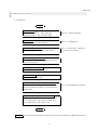
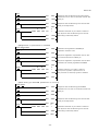
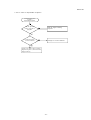
4-1.P roced ure
St art
↓
S et swi t ches
Sel ect t he st at io n N o., baud rat e and
S ee 4-2 `Swi tch Set t ing s. '
operat ion mod e of the C remot e SOT.
↓
I nst all at ion
S ee 4-4 `Inst al lat i on.'
In st al l t he S OT on the pl at form.
↓
Connect i on o f cabl es
S ee 5-1 `Connect i on
Di agra m'
Connect th e pow er and dat a li nk cab les.
5-2 `Caut ion i n W i ri ng. '
↓
Rel ocat ion of opt i cal axi s
Rel ocat e t he opt ical a xis and ch eck t he RCV
lam p on ea ch SO T.
↓
Set ti ng of m aster uni t
Set ea ch part of th e m aste r uni t.
↓
Ci rcui t check
Check th e C C-Link ci rcui t
↓
Prep aration o f tra nsm is sion /rece ption p rogram
Prepare a sequence program f or
S ee 6 `Programm ing Procedure. '
transm it t ing /recei ving dat a to and f rom t he C
re mot e S OT.
↓
Tra nsmi ssion/ recept ion st at us check
Check th e t ransmi ssio n/recept i on st at us f rom
th e C remo te SO T i nput /o utpu t sta tus and
errors dete cted by the m aste r uni t.
↓
E nd
For t he step s encl osed by do t li nes, see t he User's Manua l fo r Mast er/ Local Uni t .
- 7 -
DS4-2156
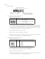
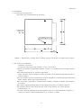
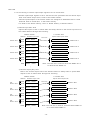
4-2.S wit ch set ti ngs
M ode select swit ches
St ati on No. select
swi tche s
Baud ra te sel ect swi t ch
4-2-1.S ett i ng t he st ati on No. se lect sw it ches
① St ati on No. se lect sw it ches
Descript i on
X1 0 sw it ch: U sed t o specif y the f irst di gi t
of t he stat i on N o.
X1 swi t ch:
Used t o speci f y t he second digi t
of t he stat i on N o.
Se lect a st at ion No. bet ween 01 and 6 4.
② The st at i on N o. shoul d be `01' w hen t here is no pre vious st ati on or `previous st ati on
No. + num ber of stat i ons occu pied by the uni t t o whi ch t he previous st ati on belo ngs.'
( If the st ati on No. of t he p revi ous stat i on i s `01' a nd t he uni t occupi es t wo st at ions,
for exampl e, t he st ati on No. of your st at ion shoul d be `03. ' )
③ The sw it ches have been fact ory-set t o `00. '
④ Take ca re not t o skip or du pli cat e any st ati on No.
⑤ Precaut ionary inst ructi ons to be f oll owed i n m akin g a connect i on w it h the CC -li nk are
shown in t he User's Manual for CC-Li nk M ast er/Local Uni t.
4-2-2.S ett i ng t he baud rate sel ect swi t ch
① Baud ra te sel ect swi t ch
No.
D escript io n
0
156 kbps
1
625 kbps
2
2. 5 M bps
3
5 Mbps
4
10 Mbps
5-9
Set t ing error ( cannot be used )
② This set ti ng must be con sist ent w it h that of t he mast er st at ion.
If not, comm uni cati on wi th t he m ast er st at ion is i mpossi ble .
③ The sw it ch has been f act ory-set to `0. '
④ Precaut ionary inst ructi ons to be f oll owed i n m akin g a connect i on w it h the CC -li nk are
shown in t he User's Manual for CC-Li nk M ast er/Local Uni t
- 8 -
DS4-2156
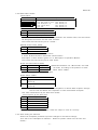
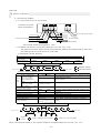
4-2-3.M ode select swi tch
① Descript i on
Descript i on
R aise t he l ever t o tu rn on.
SW1: M/S ( master or slave)
SW5: Normally off
SW2: Mode (M/S or X)
SW6: Normally off
SW3: 16th bit status
SW7: Normally off
SW4: TR E
SW8: Normally off
② M/ S select swi tch ( SW 1 )
SW 1
OFF
Mast er ( t ransmi ssion preceded )
ON
Slave ( recept ion preceded )
When dat a is comm uni cated bi -direct iona ll y bet w een t wo t ransfer uni ts, the one shoul d
be de signat ed as m ast er and t he o ther as sl ave.
The sw it ch has been f act ory-set to `mast er. '
③ Mode sel ect swi t ch ( SW 2 )
SW 2
OFF
M/ S mode
ON
X m ode
M/ S mode: Bi-di recti onal com mu nicat i on
X m ode: Bi-di rect i onal /uni -direct io nal comm uni cati on
Descript i on o f each mode i s gi ven in 4-3 `Descri pt ion of O perati on Modes. '
The sw it ch has been f act ory-set to `M/ S mod e.'
④ 16t h bi t st at us sw it ch ( S W3 )
SW 3
Inpu t
Ou tput
OFF
CTL /TCD
ON
IN 16
※
※ Swi tch ed be tw een C TL ( M/ S mode ) and TC D
RC V
( X m ode ) accordi ng t o th e posi t ion of m ode
OU T16
select swi tch ( SW 2 ) .
The sw it ch has b een f act ory-set to OF F.
⑤ TRE swi tch ( SW 4 )
SW 4
OFF
Out put cl eared i n case of
ON
Out put ret aine d i n ca se of
co unt-up
co unt-up
Count -up: E lapse of a gi ven ti me af t er t he com pl eti on of ref resh dat a re ce pti on th roug h
t he CC -Li nk and befo re t he com pl eti on of next ref resh data recept ion .
This t im e i s d eterm ined by th e bau d rat e ( f i xed ) .
Count -up ti me by the baud rat e
Baud rate
10M
Cou nt-up t im e ( m s )
104 .8
5M
104 .8
2. 5M
209 .7
625K
833 .8
156K
16 77.6
The sw it ch has b een f act ory-set to `retai n the out put in case o f count -up.'
4-2-4.A ft er set t ing t he swi tches
At tach t he namepl at e p rovi ded to prevent ch anges to t he sw it ch sett i ngs.
( The rea r of t he namep lat e is adhesi ve.
at tach. )
- 9 -
Rem ove a pl ast ic sheet from t he rear and
DS4-2156
4-3.D escri pt ion of Modes
4-3-1.M / S m ode
Set t he mode sel ect swi t ch ( S W2 ) t o OFF to sel ect t he M/ S mode.
① Desi gnat e your uni t as m ast er or sl ave.
When dat a is comm uni cated bi -d irect ional l y bet we en t wo t ra nsfer unit s, t he one shoul d
be de signat ed as m ast er and t he o ther as sl ave. S et t he M / S se lect sw it ch ( SW 1 ) to
ON t o desi gnat e your uni t as slave .
② Turn t he power supply on. T he po wer l amp ( PO W ) l igh ts.
③ When t he othe r t ransf er unit is out of the operat io nal range ( not synchroni zed ) , t he
mast er repeat s transm issi on a nd recept i on at re gular int erval s. The slave wai t s a
signal transm it t ed f rom t he m ast er.
④ When t he othe r t ransf er unit is wi thi n th e operat i onal range ( synchro nized ) :
a. A sign al is t ransm i tt ed from t he mast er t o t he sl ave.
b. The slave det ect s t he end of t he signal transm it t ed f rom t he m ast er and t ran smi ts
a si gnal i n respo nse t o it .
c. Af te r t ransm it t in g a sig nal, the m aster re ceives t he si gnal t ransmi t ted f ro m the
slave, det ects t he en d of tha t sign al, and t ransmi t s ano ther signa l. T he m ast er
and slave det ect t he end o f each signa l transm it t ed f rom t he othe r and alt ernat ely
rep eats t he transm issi on a nd recept i on.
⑤ When t he unit s are synchroni zed, t he normal dat a lam p ( DT ) l ight s.
If the receive d dat a is det ermi ned norm al , t he rel evant da ta out put t urns o n.
⑥ If the recept ion l evel drops below 12 0% of t he on-level of t he D T o utpu t due to a sta in
on t he project or/ recei ver or an opti cal axi s shi f t, th e st abi li zed recep ti on lam p ( R CV )
and t he RC V o utpu t t urn of f .
⑦ Wi t h t he 16t h bi t st at us sw it ch ( SW3 ) se t to O FF, t he rem ove input `R Y1F' on t he C
rem ot e S OT is used for transf er st op inp ut ( CTL ) .
⑧ Wi t h t he transf er st op inp ut ( CTL ) on , t he t ransf er st op l am p ( C TL ) li ght s an d, as the
transm issi on a nd recept i on are f orced ly pro hibi t ed, t he DT/ RCV l amp and al l dat a
outp uts t urn of f .
4-3-2.X m ode
① Sel ect t he X m ode
Set t he mode sel ect swi t ch ( SW 2 ) t o ON t o sel ect t he M/ S mode.
In t he X m ode, t he M/ S sele ct swi tch i s i nef fect i ve.
② Turn t he power supply on. T he po wer l amp ( PO W ) l igh ts.
③ Wi t h t he 16t h bi t st at us sw it ch ( SW3 ) se t to O FF, t he rem ove input `R Y1F' on t he C
rem ot e S OT is used for transf er st op inp ut ( TCD ) .
④ Sel ect t he t ransmi ssio n st op fu ncti on.
When dat a is comm uni cated uni -direct iona ll y bet w een t wo t ransfe r uni ts, the
transm issi on st op i nput ( TC D ) shoul d be used. Wi t h t he TCD i nput on, the
transm issi on st ops and onl y t he recep ti on rem ai ns possi bl e.
⑤ When t he othe r t ransf er unit is out of the operat io nal range ( not synchroni zed ) , t he
transf er uni t w it h the TC D i nput off re peat s t ra nsmi ssion and recept ion at regul ar
int ervals. The o ne w it h the TC D input on w ai ts a si gnal t ransm it te d f rom t he ot her.
⑥ When t he othe r t ransf er unit is wi thi n th e operat i onal range ( synchro nized ) :
a. The t ransf er u nit wit h t he TC D inp ut of f repeat s t ransmi ssio n and recept ion at
reg ular int ervals.
b. I f t he o ne w it h the TC D i nput on n orm all y recei ves an o pti cal si gnal f rom th e ot her,
it turns th e D T and rele vant dat a outp ut on.
c. I f t he TC D inpu t t urns of f at t hi s t i me, data can be bi-di re ct i onal ly comm uni cated
as i n the M /S m ode.
- 10 -
DS4-2156
4-4.I nst all at io n
4-4-1.D ri l li ng m ount i ng hol es
M4 screws are recomm ended f or mo unti ng.
O pt ical axi s
direct i on
A threade d hol e tha t
accomm odat es an M 4
※ Not e 1: Ti ght en t he C remot e SOT mou nti ng screw s t o a t orque not hi gher than 8 kgf -cm .
4-4-2. Pl ace f or inst al lat i on
Inst al l t he un it i ndoor.
To prevent mal f uncti on and disorder, do not use i t w here:
① the re may be dust , suspended part icl es or wat er o r oi l splashe s t hat w il l dam p op ti cal
signal s,
② an eva pora ted sol vent or co rrosi ve gas exi sts,
Not e: The ma in body is made of a resi n and m ust not b e cl eaned wi th pai nt t hi nner or
anot her sol vent .
③ a l ig ht cont ain ing much i nf rared rays such as su nli ght or incan descent l ight ( dist urbi ng
li ght ) direct ly ent ers t he proj ect or/recei ver,
④ the uni t m ay be exposed t o a t emp erat ure, hu mi dit y, vi brati on or i mpact that exceeds
the rat ing,
⑤ the SO T's opt ical p assage m ay be i nt errupt ed by a person or ano ther obst acle,
⑥ a ref lect i ng su rf ace may draw near t he front of t he recei ver ( t o cause o pti onal
int er ef eren ce ) , or
⑦ a devi ce tha t wi ll generate a strong m agnet ic fi el d ( e. g. elect romagn eti c co ntact or o r
mot or ) or a source of rad io freque ncies ( e. g. i nvert er ) is used.
- 11 -
DS4-2156
5. Elect ric Conn ecti on
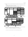
5-1.C onnect ion di agram
5-1-1.C onnect ion of t he C remot e SOT
Conn ector term inal
bl ock arrangem ent
Bl ue Wh ite Yellow Brai de
For 24 VD C pow er supply
From pr evious s tation
For n e xt st at ion
CC-Lin k de dica ted c able
CC-Lin k ded ica ted ca ble
Each cable shoul d be st ripp ed t o 7 m m.
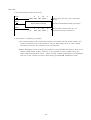
5-1-2.M ut ual connect i on of li nk data cabl es ( f or C C-Link, Ver. 1. 10 )
The stat i on-to-st ati on dist ance and t otal exten sion di stance are dete rm ine d by t he ba ud
rat e set ti ng and the const ructi on of uni t s used.
① Maxi mum transf er di st ance
Baud rat e
1 56kbps
625kbps
2 0 cm or more
Sta tio n -to-st at ion
cable length
Maximum t ransfer
dist ance
1 200m
2.5 Mbps
900m
5M bps
400m
160 m
10M bps
100m
M axi mum t ransfe r di stance
R
R
M
R
R
R
M : Mast er st at io n
T ermi nal resi stor
T erminal resi sto r
R : Rem ote st at ion
② For T branch connect ion
Bau d ra te
Stationtostat ion
cable
length
156k bps
6 25k bps
1 m or mo re
Between master/local
stat ion or int elligent
device station and
pr evious/subsequent
stat ion
※1
Bet ween r emote I/ O
station and remote
device station
※2
2 m o r m ore
30 cm o r m ore
Ma xim um n umb er of units
co nne cted p er branc h
Ma xim um tru nk le ngth
※3
T bran ch in terval
Ma xim um b ra nch leng th
Tota l branc h len gth
Term inal res is tor
T bran ch term inal
blo ck /con nec tor
2.5M /5M/1 0Mb ps u nac cep table
For the s ys tem on ly c ons istin g of remo te I/O a nd
re mote dev ice s tatio ns
For the s ys tem in clud ing lo cal a nd inte llige nt
dev ice s tatio ns
6
500m
※4
1 00m
Exc ludin g ca bles between termin al resis tors a nd
branc hes
No t limi ted
8m
200m
50m
110 Ω 1/2 W × 2
T erminal blo ck:
A commercial one
Con nector :
F A se nsor connect or
Ca ble le ngth p er b ra nch
Total le ngth o f b ranc hes
Co nnec ted b etween DA an d DB a t tru nk en ds
Trunk c abl es s houl d be st rip ped to a sho rte r
leng th.
※3
※4
R
※2
R
※1
M
R
※1
※2
R
※2
R
※1
T ermi nal resi stor
L
Te rmi nal resis tor
※1 ※1
R
M : Master
st ation
※2
L
L : Local
※1
R
※1
L
※2
R
or intelligent device statio n
R
R : R emote
I/O or d e vice station
N ote: Al l unit s and cables on th e syst em shoul d be com pat ibl e wi th t he CC-Li nk, Ver. 1. 10.
- 12 -
DS4-2156
5-1-3.M ut ual connect i on of li nk data cabl es ( wh en un it s ol der than t he CC-Li nk, Ver. 1. 10 are
used )
The stat i on-to-st ati on dist ance and t otal exten sion di stance are dete rm ine d by t he ba ud
rat e set ti ng and the const ructi on of uni t s used.
( The fol lo wi ng t abl e a ppli es when FAN-SB and FAN C-SBH are used. )
① For t he system only consi sti ng of remot e I/ O and remot e device st at ions
Baud ra te
Total number
C able leng th at ea ch
Minimum cable length
of re mot e
end of master stat ion
between remote
*2
stations *3
stat ions
156 Kbps
625 Kbps
2.5 M bps
5 Mb ps
*1
64 or les s
1.0 m or m ore
T otal cable extension *4
FA NC-SB
0 .3 m or mo re
0 .6
0 .3
0 .4
0 .6
0 .7
1 .0
0 .3
0 .4
0 .3
1 0 Mbp s
48 or les s
32 or les s
m
m
m
m
m
m
m
m
m
or
or
or
or
or
or
or
or
or
1 200
600
200
110
150
50
mo re
mo re
mo re
mo re
mo re
mo re
mo re
mo re
mo re
m
m
m
m
m
m
or
or
or
or
or
or
FAN C-SBH
l ess
les s
les s
les s
les s
les s
120 0
9 00
4 00
1 60
m
m
m
m
or
or
or
or
les s
le ss
le ss
le ss
20 m or l ess
30 m or l ess
8 0 m or les s
1 00 m o r le ss
100 m or les s
5 0 m or les s
80 m or l ess
1 00 m o r le ss
*1
M
R
*2
R
*3
*3
R
R
R
*3
M : Mast er st at io n
T ermi nal resi stor
R : Rem ote st at ion
T erminal resi sto r
*4
② For t he syste m incl udi ng l ocal and i nte ll ige nt devi ce st at ion s
Baud ra te
156 Kbps
625 Kbps
2.5 M bps
5 Mb ps
Minimum cable length
master , local and intelligent
betwe en remote I/O and
device stations
remot e device stations
*1
2.0 m or more
0.3 m or m ore
0.6
0.3
0.6
0.7
1.0
1 0 Mbp s
M
T otal cable extension
Cable length at each end of
R
*1
*2
R
m
m
m
m
m
R
or
or
or
or
or
*2
m
m
m
m
m
m
m
or
or
or
or
or
or
or
less
les s
les s
les s
les s
les s
les s
12 00
600
200
110
150
L
*1
L
*1
m
m
m
m
m
or
or
or
or
or
les s
le ss
le ss
le ss
le ss
50 m or less
80 m or less
100 m or les s
*1
*3
FAN C-SBH
*2
1 200
600
200
110
150
50
80
m ore
m ore
m ore
m ore
m ore
R
F ANC-SB
R
T ermi nal resi sto r
Termin al resist or
*3
M : Mast er
stat ion
L : Local
or intelligent device statio n
R : R emote
I/O or d e vice station
I nstal l t he term inal resi st or provide d w it h the m aster/ loca l unit at each end of t he dat a
li nk cable.
The term inal resi st or t ype de pends o n t he cable .
Inst al l 110 Ω fo r FAN C-SB or FAN C-SBZ or 13 0 Ω f or FA NC-SBH .
For det ai l, see t he User's Man ual f or CC -L ink Syst em Mast er/ Local Uni t .
- 13 -
DS4-2156
5-1-4.M axim um num ber of unit s connect ed
The C rem ot e S OT is a rem ot e I / O stat i on a nd occup ies a si ngl e st at io n.
Up t o 64
SOT s m aybe con necte d.
When ot her u nit s a re t o be connect ed, the f oll ow ing condi ti ons shoul d be me t.
①{(1×a)+(2×b)+(3×c)+(4×d)}≦64
a: Num ber of uni ts th at occupy a si ngl e st at io n each
b: Num ber of uni ts th at occupy tw o st at i ons each
c: Num ber of unit s tha t occupy three st ati ons each
d: Num ber of uni ts th at occupy fo ur st ati ons each
②{(16×A)+(54×B)+(88×C)}≦2304
A: Nu mber of remot e I/ O st ati ons
B: Nu mber of remot e device st at ions
C: N umber of l ocal, stand by m aste r and int el li gent device st ati ons
5-2.C aut ion i n w irin g
( 1 ) The dat a l in k cabl e sh ould be connect ed wi th a CC-Li nk de dicat ed cable .
( 2 ) The shiel ded ( braide d ) cable t o be conne ct ed t o t he connect or t ermi nal bl ock sh ould be
stri pped to as smal l a leng th as possibl e.
( 3 ) I nstal l t he term inal resi st or provide d w it h the m aster/ loca l unit at each end of t he dat a
li nk cable.
( 4 ) Usi ng a noi se fi lt er, E MI f i lt er and /or ferrit e core w it h the pow er cabl e m ay be ef f ect ive
to suppress th e noi se at t he power su pply.
( 5 ) Pow er cabl e ext ensi on
The power cable ext ensio n shoul d be as short as possi ble and mu st not exceed 50 m.
Use a ca ble wi t h 0. 3 mm 2 o r t hicker conduct or.
( Inst al l a reg ulat ed volt age pow er suppl y w it hi n 50 m .
adj usted i n con si derat ion of vol tage drop.
The ext ensi on sho uld be
A shi eld ed po wer cabl e is recomm ended.
( 6 ) The fo ll owi ng i nst ructi ons should be observed in routi ng t he dat a li nk cable s t o p rot ect
th em from no ises and surge s.
① The data l ink and power cable s m ust not be l aid near or bundl ed t oget her wi t h t he
mai n ci rcuit or any li ne wi th a high vol ta ge or load ( shoul d be a t lea st 100 mm aw ay
from t hem ) .
② The data l ink and power cable s t o t he C remot e SOT shoul d a lso be separated .
( 7 ) No conduct or shou ld protrude f rom the cabl es co nnecte d t o the connect or term inal b lock.
Braide d w ires should be in su lat ed using t ubes or such to prevent the cont act w it h othe r
wi re s.
( 8 ) Cabl es should be secured so t hat con ductors wi ll n ot be cut due t o vi brati on.
- 14 -
DS4-2156
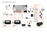
6. Pro gram mi ng Procedure
6-1.O utl i ne o f dat a exch ange
6-1-1Dat a e xch ange fl ow
The data exchang e f l ow betw een the C remot e SOT and t he mast er st at ion i s out l ined
belo w.
Seque ncer CP U
M ast er st at ion
R emot e I/ O st at ion
①
[ SET Yn0 ]
C remot e SOT
Re fresh comm and
②
[ SET Yn6 ]
Da ta li nk start
Buf f er m emory
④
[
FRO M ]
③
Re mot e input
( RX )
⑤
[
TO
]
L ink scan
Op ti cal dat a input s
( OU T1-OUT1 6 )
⑥
Re mot e outpu t
( RY )
L ink scan
Op ti cal dat a outp uts
( I N 1-I N 16 )
① The ref resh co mm and ( Y n0 ) turns on.
② The reque st f or dat a li nk st art ( Yn6 or Y n8 ) t urns on.
③ The li nk i s scan ned t o sto re t he o pti cal dat a inpu ts ( OU T ) from t he C rem ot e S OT in
the remot e inp ut ( RX ) a rea of t he mast er stat i on.
④ Dat a i s uploa ded f rom t he rem ot e i nput ( R X ) area o f t he m ast er st ati on according t o
the FR OM comm and.
⑤ Dat a i s downl oaded f rom t he remot e out put ( RY ) area of the ma ster stat i on a ccordi ng
to t he T O co mm and.
⑥ The li nk i s scan ned t o send dat a i n the remot e out put ( RY ) are a of the m aster stat i on
to t he o pti cal dat a out puts ( I N ) of t he C remot e SOT.
- 15 -
DS4-2156
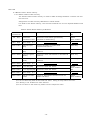
6-1-2.P rocessi ng of remot e in put/ out put si gnal s o f t he C rem ote SO T
Rem ote i nput /ou tput signa ls of t he C rem ot e S OT are processed via t he rem ot e i nput
( RX ) and remot e out put ( R Y ) are as of the m aster sta ti on.
Rem ot e i nput s/o utpu ts of t he mast er st at ion are assigne d t o addresses E0 H to 15FH
( RX ) an d 160H t o 1DFH ( R Y ) in t he buff er mem ory.
For det ai l of t he buf fer mem ory, see 6-3 `Buf f er me mory of mast er st at io n.'
① Rem ot e i nput ( RX ) area
Opt i cal dat a i nput s o f t he C rem ote SO T are alw ays st ored in t he rem ot e i nput area of
t he m ast er st ati on th roug h l ink scanni ng.
Mast er st at ion
Addres s
Sta tion No.1
Sta tion No.2
Sta tion No.3
Sta tion No.4
Rem ote in put ( RX )
C rem ote SO T
O pti cal d ata inp uts ( O UT )
Lin k sc an
E0H
RX0F -RX00
O UT1 - 8
E1H
RX1F -RX10
O UT9 - 16 ( R CV )
E2H
RX2F - R X20
O UT1 - 8
E3H
RX3F - R X30
O UT9 - 16 ( R CV )
E4H
RX4F - R X40
O UT1 - 8
E5H
RX5F - R X50
O UT9 - 16 ( R CV )
E6H
RX6F - R X60
O UT1 - 8
E7H
RX7F - R X70
O UT9 - 16 ( R CV )
E8H
RX8F - R X80
St at ion No. 1
St at ion No. 2
St at ion No. 3
St at ion No. 4
Not e: T he 16t h bi t is used fo r RC V w it h DSW 3 off or
…
for OUT 16 w it h DSW 3 on.
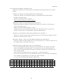
② R emot e out put (RY ) area
Dat a i n the remo te out put area of t he mast er st at io n i s al ways sent t o opt ical data
outp uts of t he C re mot e S OT th roug h l ink scanni ng.
Mast er st at ion
Addres s
For
s tati on No.1
C rem ote SO T
Rem ote ou tput ( RY )
Opt ical d ata ou tputs ( IN )
160H
RY0F - R Y00
161H
RY1F - R Y10
IN 9 -16 ( CT L/TC D )
Lin k sc an
IN 1 -8
For
s tati on No.2
162H
RY2F - R Y20
IN 1 -8
163H
RY3F - R Y30
IN 9 -16 ( CT L/TC D )
For
s tati on No.3
164H
RY4F - R Y40
IN 1 -8
165H
RY5F - R Y50
IN 9 -16 ( CT L/TC D )
166H
RY6F - R Y60
IN 1 -8
167H
RY7F - R Y70
IN 9 -16 ( CT L/TC D )
168H
RY8F - R Y80
For
s tati on No.4
St at ion No. 1
St at ion No. 2
St at ion No. 3
St at ion No. 4
Not e: T he 16 th bi t is used f or CTL/ TC D wi th DSW 3 of f
…
or f or I N16 wi t h D SW 3 on.
- 16 -
DS4-2156
6-2.M ast er st ati on inp ut/ out put si gnal s
The mast er st at ion i nput /o utpu t sign als to and f ro m the CP U unit are l ist ed bel ow.
For de tai l of the i nput /out put signal s, see t he User's Manual for CC-Li nk S ystem
Mast er/ Local Un it .
`n' in t he de vice No. co lum n represent s t he st art i ng I/ O No. of t he m ast er st at ion, whi ch i s
det ermi ned b y t he number of uni t s i nsta ll ed in front of t he mast er st at ion.
I f t he star t ing I / O No. of the m aster sta ti on is X/ Y20, f or e xampl e:
X ( n + 0 ) -X ( n + 1F )= X20-X3F
Y ( n + 0 ) -Y ( n + 1F )= Y20-Y3F
I /O Si gnal L ist
Device No.
Signal name
Device No.
Xn0
Unit failure
Yn0
Xn1
Your station data-linked
Yn1
Xn2
Parameters set
Yn2
Signal name
Refresh command
(Not used)
Xn3
Other station data-linked
Yn3
Xn4
Request for unit reset accepted
Yn4
Request for unit reset
Xn5
(Not used)
Yn5
(Not used)
Xn6
Data linking per buffer memory
parameters normally started
Yn6
Request for data linking per buffer
memory parameters
Xn7
Data linking per buffer memory
parameters abnormally started
Yn7
(Not used)
Xn8
Data linking per E PROM parameters
normally started
2
Yn8
Request for data linking per E PROM
parameters
Xn9
Data linking per E PROM parameters
abnormally started
2
Yn9
(Not used)
XnA
Parameters normally registered in
2
E PROM
YnA
Request for registration of parameters in
2
E PROM
XnB
Parameters abnormally registered in
2
E PROM
YnB
XnC
XnD
XnE
XnF
X(n+1)0
X(n+1)1
X(n+1)2
X(n+1)3
X(n+1)4
X(n+1)5
X(n+1)6
X(n+1)7
X(n+1)8
X(n+1)9
X(n+1)A
X(n+1)B
X(n+1)C
X(n+1)D
X(n+1)E
X(n+1)F
(Not used)
Unit ready
(Not used)
YnC
YnD
YnE
Y(n+F)
Y(n+1)0
Y(n+1)1
Y(n+1)2
Y(n+1)3
Y(n+1)4
Y(n+1)5
Y(n+1)6
Y(n+1)7
Y(n+1)8
Y(n+1)9
Y(n+1)A
Y(n+1)B
Y(n+1)C
Y(n+1)D
Y(n+1)E
Y(n+1)F
- 17 -
2
(Not used)
DS4-2156
6-3.M ast er st ati on buf fer mem ory
6-3-1.M ast er st ati on buf fer mem ory
The mast er st at ion buf f er m emory i s used f or data exchang e bet we en a remot e uni t and
the C PU unit .
Assig nment of buf f er me mory ad dresse s i s show n be low .
For det ai l of t he buf fer mem ory, see the Use r' s M anual f or C C-Lin k Syst em M aster/ Local
Uni t.
Mast er S tat i on B uff er Mem ory Addresses
Add ress
It em
Descri pti on
Read/ wri te
※3
(hex ade cim al)
0H - 5F H
Paramet er
inf ormat i on a rea
St ores t he i nform ati on (p aram et ers)
requi red f or dat a li nki ng.
Read/
writ e enabl ed
※1
60H - D FH
(N ot use d)
E0H -1 5FH
Remote inpu t
(RX)
Stores the sta tu s of in puts from
remo te /local sta tions.
Rea d o nly
16 0H -1 DFH
Remote o utput
(RY)
Sto res th e st at us of out puts t o rem ot e/l ocal
st at ions.
Wri te onl y
1E0 H -2D FH
Rem ote regi ster
(R Ww )
St ores t he dat a transm it t ed t o re mot e/ local
st at ions.
Wri te onl y
2E0 H -3D FH
Rem ote regi ster
(R Wr)
St ores t he dat a recei ved from rem ote/ l ocal
st at ions.
Read onl y
3E0 H -5D FH
(N ot use d)
5E0H -5FFH
Lin k relay(SB)
St ores t he dat a li nk st at us.
60 0H -7 FFH
Lin k register(SW)
St ores t he dat a li nk st at us.
Read/
writ e enabl ed
※2
80 0H -9 FFH
(Not us ed)
A0 0H -FFFH
Rand om acce ss
buffe r
Use d f or ded icat ed inst ructi ons such as
RI RD a nd R IW T.
Read/
writ e enabl ed
※1
※1
※ 1: Do not writ e any d ata i n t he areas not used.
D oing so may le ad t o an error.
※ 2: W ri t ing i s not enabl ed f or some devi ce s.
※ 3: Do not writ e in t he read-onl y a reas f ro m the sequen ce r CPU .
- 18 -
DS4-2156
6-3-2.S ett i ng t he paramet er inf ormat i on area
Speci fy t he con dit io ns f or da ta li nki ng i n th e param ete r in form ati on are a of the m aster
stat i on.
① Num ber of st at io ns conne cted (address 01 H, def aul t ed 64)
Speci fy th e num ber o f remot e/ local stat i ons con nected w it h t he ma ster stat i on
(i nclu ding reserved on es).
Speci fy a n umber bet ween 1 a nd 64 .
This is not the num ber of occupied st at ions.
② Maxi mum n umber of retri es (address 02H, defa ult ed 3)
Speci fy th e m axim um num ber of ret ries t o b e m ade for a rem ote or local st at io n i n
case of dat a l inki ng error.
Speci fy a n umber bet ween bet ween 1 and 7 .
If data l inki ng is not no rm all y perf ormed af t er t he specif i ed num ber o f retri es, t he
rem ot e or local stat i on i s considered as `da ta li nk fai l ed st at io n.'
③ Num ber of a utom at ical ly reset st at ions (address 03 H, def aul t ed 1)
Speci fy th e num ber o f remot e/ local stat i ons t hat can be reset duri ng a si ngle l ink scan.
Speci fy a n umber bet ween 1 a nd 10 .
④ Operat ion st atu s i n case of CPU breakdow n (address 06H, de faul t ed 0)
Choose t o cease t he data l inki ng (set to 0) or cont inu e (set t o 1) wh en t he CPU uni t of
the m aster stat i on `st ops due to an error. '
⑤ Reserved stat i ons (addresses 10H t o 13H , def aul te d 0)
Any o f t he rem ote/ l ocal st at ions speci fi ed as conn ected but not act ual ly connect ed
may be co nsidered as data l ink f ail ed.
To prevent t hi s, set t he relevan t bit (s) t o 0.
If any of the remo te/ l ocal st ati ons act uall y con necte d i s speci f ied as re served, it wi ll
never be dat a-li nked.
Set on t he b it s correspondi ng to t he st at i on N os. of reserved sta ti ons.
For t he unit occupying t wo or m ore rem ote/ l ocal st ati ons, se t on the bi t correspondi ng
to t he st at io n N o. speci fi ed by t he st ati on No. se lect sw it ches.
1 t o 64 i n the f ol low ing t able represent st at ion Nos.
Address b15 b14 b13 b12 b11 b10
b9
b8
b7
b6
b5
b4
b3
b2
b1
b0
10H
16
15
14
13
12
11
10
9
8
7
6
5
4
3
2
1
11H
32
31
30
29
28
27
26
25
24
23
22
21
20
19
18
17
12H
48
47
46
45
44
43
42
41
40
39
38
37
36
35
34
33
13H
64
63
62
61
60
59
58
57
56
55
54
53
52
51
50
49
- 19 -
DS4-2156
⑥ Error inval i d st at ion ( addresses 14H t o 17H , def aul ted 0 )
Local/ remot e st ati ons specif i ed a s error i nvali d are not co nsidered as 'dat a li nk f ai led'
by t he mast er an d rem ote st ati ons if the y cannot be data-l inke d due t o p ower f ai lure
or f or anot her reason .
Not e tha t no error can be det ect ed at error inva li d st at ion s.
If they are a lso speci fi ed as reserved, t hey are consi dered as not connect ed.
Set on t he b it s correspondi ng to t he st at i on N os. of t he st ati ons to be error-in vali d.
For t he unit occupying t wo or m ore rem ote/ l ocal st ati ons, se t on the bi t correspondi ng
to t he st at io n N o. speci fi ed by t he st ati on No. se lect sw it ches.
1 t o 64 i n the f ol low ing t able represent st at ion Nos.
Address b15 b14 b13 b12 b11 b10
b9
b8
b7
b6
b5
b4
b3
b2
b1
b0
14H
16
15
14
13
12
11
10
9
8
7
6
5
4
3
2
1
15H
32
31
30
29
28
27
26
25
24
23
22
21
20
19
18
17
16H
48
47
46
45
44
43
42
41
40
39
38
37
36
35
34
33
17H
64
63
62
61
60
59
58
57
56
55
54
53
52
51
50
49
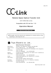
⑦ St ati on inf ormat i on ( a ddre sses 20H t o 5FH )
Speci fy th e t ype of each of t he remot e/ local stat i ons con nected or specif i ed as
reserved.
Dat a struct ure
b15
-
b12 b 11
St ati on typ e
-
b8 b7
-
0: C remot e SOT
b0
Station
N umber of
occupied stations
1∼64
1: Sing le sta ti on
occupi ed
( 01H -4 0H )
( re mot e I / O st ati on )
Buf fer mem ory addresses are assi gned t o uni t s as shown bel ow.
Uni t
Address
Un it
Addr ess
Uni t
Address
U nit
Address
1 st
20H
17 th
30H
33 rd
40H
49 t h
2 nd
21H
18 th
31H
34 t h
41H
50 t h
51 H
3 rd
22H
19 th
32H
35 t h
42H
51 st
52 H
4 th
23H
20 th
33H
36 t h
43H
52 nd
53 H
5 th
24H
2 1 st
34H
37 t h
44H
53 rd
54 H
6 th
25H
2 2 nd
35H
38 t h
45H
54 t h
55 H
7 th
26H
2 3 rd
36H
39 t h
46H
55 t h
56 H
8 th
27H
24 th
37H
40 t h
47H
56 t h
57 H
9 th
28H
25 th
38H
41 st
48H
57 t h
58 H
10 th
29H
26 th
39H
42 nd
49H
58 t h
59 H
11 th
2AH
27 th
3A H
43 rd
4AH
59 t h
5A H
12 th
2BH
28 th
3B H
44 t h
4BH
60 t h
5B H
13 th
2CH
29 th
3C H
45 t h
4CH
61 st
5C H
14 th
2DH
30 th
3D H
46 t h
4DH
62 nd
5D H
15 th
2EH
3 1 st
3E H
47 t h
4EH
63 rd
5E H
16 th
2FH
3 2 nd
3FH
48 t h
4FH
64 t h
5F H
- 20 -
50 H
DS4-2156
6-3-3.I nput s/ out puts of C rem ote SO T
Opt ical dat a i nput s of th e C remo te SO T are alw ays st ored in t he rem ote i nput ( R X )
are a i n the buf f er me mory o f t he m ast er st ati on th roug h l ink scanni ng.
Dat a in th e rem ote out put ( R Y ) area i n th e buf f er m emory of t he m ast er st at ion i s
alw ays sent to opt i cal dat a o utpu ts of t he C rem ot e S OT through l ink scanni ng.
Rem ote I nput s/O utp uts
Si gnal di re cti on:
C rem ot e S OT → Mast er uni t
Devi ce N o.
RX0 0
Sig nal di rect i on:
M ast er uni t → C remot e SOT
D escri pt ion
Devi ce N o.
O pti cal da ta inp uts O UT 1 RY0O -R X0F
De scri pt ion
No t used
RX0 1
〃
OUT 2
RY10
RX0 2
〃
O UT 3
RY11
〃
IN 2
RX0 3
〃
OUT 4
RY12
〃
IN 3
Optic al da ta outp uts
IN 1
RX0 4
〃
OUT 5
RY13
〃
IN 4
RX0 5
〃
OUT 6
RY14
〃
IN 5
RX0 6
〃
OUT 7
RY15
〃
IN 6
RX0 7
〃
OUT 8
RY16
〃
IN 7
RX0 8
〃
OUT 9
RY17
〃
IN 8
RX0 9
〃
OUT10
RY18
〃
IN 9
RX0 A
〃
O UT 11
RY19
〃
IN 10
RX0 B
〃
OUT12
RY1A
〃
IN 11
RX0 C
〃
OUT13
RY1B
〃
IN 12
RX0 D
〃
OUT14
RY1C
〃
IN 13
RX0 E
〃
OUT15
RY1D
〃
IN 14
〃
IN 15
RX0 F
SW 3 O FF R C V
〃
SW 3 O N
RX1 O-RX1F
RX1E
O UT16
N ot used
RY1F
S W3 O FF C T L / T C D
S W3 0N
O ptic al da ta outp uts
I N16
① OUT1 t o 16 ( R X00 to RX 0F )
Out put s t he dat a sent from t he normal S OT.
② RVC ( RX 0F )
Set t o '1' duri ng st abi li zed recep ti on.
Wi th SW 3 on, R X0F is swi tched t o O UT16 and cannot be use d.
③ IN 1 t o 16 ( R Y10 t o R Y1F )
Inpu ts t he dat a t o be t ra nsmi tt ed t o t he normal S OT.
④ CTL/ TCD ( R Y1F )
The t ransm issi on an d recept io n are ceased wi th SW 2 off and R Y1F on ( CTL ) .
The t ransm issi on i s ce ased w it h SW 2 on and RY1 F on ( TCD ) .
Wi th SW 3 on, R Y1F is swi tched t o I N 16 an d canno t be used.
- 21 -
DS4-2156
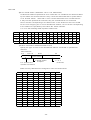
6-3-4.R emot e inp ut ( RX ) area
Rem ote i nput s of the C remot e SOT are stored in t he rem ot e i nput a rea i n t he buf fer
mem ory of the ma ster stat i on a t t he rel evant add resses.
The corresponde nce be tw een t he st ati on No. o f t he C rem ote SO T an d t he appl icabl e
buf fer mem ory address is shown bel ow.
Mast er S tat i on Buf fer Mem ory Add resses ( C Rem ot e SO T → M ast er St at ion ( RX ))
Station
No.
Buf fer
memor y
Station
N o.
address
Buff er
memory
Station
No.
address
Buf fer
memor y
Station
N o.
address
Buff er
memory
Station
No.
address
Buf fer
memor y
address
1
E0H-E1H
14
FAH-FBH
27
114H-115H
40
12EH -12F H
53
148H-14 9H
2
E2H-E3H
15
FCH-FDH
28
116H-11 7H
41
13 0H-131H
54
14AH-14BH
3
E4H-E5H
16
FEH-FFH
29
118H-11 9H
42
13 2H-133H
55
14CH-14DH
4
E6H-E7H
17
1 00H-101H
30
11AH-11BH
43
13 4H-135H
56
14EH-14FH
5
E8H-E9H
18
1 02H-103H
31
11CH-11DH
44
13 6H-137H
57
150H-15 1H
6
EA0-EBH
19
1 04H-105H
32
11EH-11F H
45
13 8H-139H
58
152H-15 3H
7
ECH-EDH
20
1 06H-107H
33
120H-12 1H
46
13 AH-1 3BH
59
154H-15 5H
8
EEH-E FH
21
1 08H-109H
34
122H-12 3H
47
13 CH-13 DH
60
156H-15 7H
9
F0H-F1H
22
1 0AH-1 0BH
35
124H-12 5H
48
13 EH-1 3FH
61
158H-15 9H
10
F2H-F3H
23
1 0CH-10 DH
36
126H-12 7H
49
14 0H-141H
62
15AH-15BH
11
F4H-F5H
24
1 0EH-1 0FH
37
128H-12 9H
50
14 2H-143H
63
15CH-15DH
12
F6H-F7H
25
1 10H-111H
38
12AH-12BH
51
14 4H-145H
64
15EH-15FH
13
F8H-F9H
26
1 12H-113H
39
12CH-12DH
52
14 6H-147H
−
−
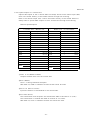
6-3-5.R emot e out put ( RY ) area
Rem ote out put s t o t he C rem ote SO T are sto red i n t he re mot e outp ut area in th e buf f er
mem ory of the ma ster stat i on a t t he rel evant add resses.
The corresponde nce be tw een t he st ati on No. o f t he C rem ote SO T an d t he appl icabl e
buf fer mem ory address is shown bel ow.
Mast er S tat i on Buf fer Mem ory Add resses ( Mast er Sta ti on ( RY ) → C Rem ot e S OT )
Station
No.
Buf fer
memor y
Station
N o.
address
Buff er
memory
Station
No.
address
Buf fer
memor y
Station
N o.
address
Buff er
memory
Station
No.
address
Buf fer
memor y
address
1
160 H-16 1H
14
1 7AH-1 7BH
27
194H-19 5H
40
1AE H-1AF H
53
1C8H-1C9H
2
162 H-16 3H
15
1 7CH-17 DH
28
196H-19 7H
41
1B0 H-1 B1H
54
1CAH-1 CBH
3
164 H-16 5H
16
1 7EH-1 7FH
29
198H-19 9H
42
1B2 H-1 B3H
55
1CCH-1CDH
4
166 H-16 7H
17
1 80H-181H
30
19AH-19BH
43
1B4 H-1 B5H
56
1CEH-1 CF H
5
168 H-16 9H
18
1 82H-183H
31
19CH-19DH
44
1B6 H-1 B7H
57
1D0H-1D1H
6
16A0 -1 6BH
19
1 84H-185H
32
19EH-19F H
45
1B8 H-1 B9H
58
1D2H-1D3H
7
16CH-16DH
20
1 86H-187H
33
1A0H-1A1H
46
1BA H-1BBH
59
1D4H-1D5H
8
16EH-16F H
21
1 88H-189H
34
1A2H-1A3H
47
1BCH-1BDH 6 0
1D6H-1D7H
9
160 H-17 1H
22
1 8AH-1 8BH
35
1A4H-1A5H
48
1BE H-1BF H
61
1D8H-1D9H
10
172 H-17 3H
23
1 8CH-18 DH
36
1A6H-1A7H
49
1C0 H-1C1H
62
1DAH-1 DBH
11
174 H-17 5H
24
1 8EH-1 8FH
37
1A8H-1A9H
50
1C2 H-1C3H
63
1DCH-1DDH
12
176 H-17 7H
25
1 90H-191H
38
1AAH-1ABH
51
1C4 H1 C5 H
64
1DEH-1 DF H
13
178 H-17 9H
26
1 92H-193H
39
1ACH-1 ADH 5 2
1C6 H-1C7H
−
−
- 22 -
DS4-2156
6-4.D ata processi ng t i me
The dat a processi ng ti me by the C remot e SOT i s cal cul ated as fo ll ows.
6-4-1.Ti me requi re d f or t ransmi t ti ng dat a
Maxi mum p rocessi ng ti me =
M S + LS x 2 + opt ica l transf er t i me x 2
6-4-2.Ti me requi re d f or up loadi ng re ceived dat a
Maxi mum p rocessi ng ti me = MS x 2 + LS x 2
MS: Scan ti me by sequence progra m of ma ster stat i on
LS: Li nk sca n t im e
Opt ical transf er t im e: Ti me requi red f or opt i cal t ransf er f rom C remot e SOT t o
norm al SOT
M /S m ode : 20m s M AX
X mo de
: 30m s M AX
The li nk sca n t im e for th e C C-Link i s cal culat ed as fol l ows.
LS = BT{29. 4 + (NI ×4. 8) + (N W×9. 6) + (N×32. 4) + (n i×4. 8) + (nw×9. 6)} + S T
*2
+ {n umber of com muni cat ion f ail ed stat i ons x 48 x B T x numb er of ret ries}
*2 : This t erm is re quired when one or m ore com mun icat io n f ai led st ati ons exist .
BT: A const ant ( bau d rat e )
NI : The largest stat i on N o. of a, b and c
( i ncl uding al l occupi ed stat i ons )
NW : The lat est st at io n N o. of b and c
A m ult i ple of 8
( i ncl uding al l occupi ed stat i ons )
N: N umber of connect ed sta ti ons
ni: a + b + c
nw: b + c
ST: A const ant ( t he largest of ① , ② and ③ )
① 8 00 + (a× 15)
② 9 00 + (b× 50)
③ I f c ≦ 26, 1 200 + ( c x 100 )
I f c > 26, 3 700 + {( c - 26 ) x 25 }
a: The t otal number of occupi ed re mot e I / O st ati ons
b: The t otal number of occupi ed re mot e d evice st ati ons
c: The to tal n umber of occupi ed int el li gent de vice sta ti ons ( i ncl udin g l ocal ones )
- 23 -
DS4-2156
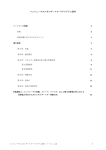
6-5.P rogram mi ng
Prepare a PC program usi ng the f ol low ing exam ple.
Thi s sect i on gi ves a descri pt ion assumi ng t he A CPU, AJ61bT11 and C remot e SOT
set as f oll ows f or your ref erence.
Exa mpl e of sy ste m co nstruc tion
① A J61 BT11 is insta lled i n 0 slo t.
0 sl ot
P o w er s u pp ly u n it
② S tation No. o f C rem ote SO T is 1.
③ O nl y a si ngle C rem ote SO T is
c onn ecte d.
④ T ra nsm itted data is store d at
A J61
BT 11
AC PU
B0 010 to B0 01F an d rece ive d
d ata at B00 00 to B00 0F.
・ S tat i on N o. 01
6-5-1.P aram et ers set t ing program
An exampl e prog ram f or sett i ng pa ram et ers i s show n be low .
① Dat a l i nking per buff er m em ory parame ters ( in debuggi ng )
M9038
[SET
Y0000]
Refresh command
[PLS
M302]
Parameter information is written in buffer memory
X0000 X000F
M302
K
[MOV
1
[MOV
5
[MOV
with no unit failure and with Unit Ready on.
D0
]
A single station connected
D1
]
5 retries
1
D2
]
A single station automatically reset
D0
3
]
0
D3
]
D3
1
]
D4
]
K
K
[TO
H
H
0000
0001
K
K
[MOV
[TO
H
H
0000
0006
K
Operation status in case of CPU breakdown
(stop )
H
[MOV
[TO
H
H
0000
0020
0101
K
D4
1
- 24 -
Remote station information
Station No. 1, 1 station occupied
]
Remote I/O station
DS4-2156
M302
[SET
M303 ]
Request for start of data linking per buffer memory
[SET
Y0006]
Ready on.
[RST
Y0006]
M303
parameters turns on with no unit failure and with Unit
X0006
Request for start of data linking turns off when data
linking is normally started.
[RST
X0007
[FROM
H
0000
H
0668
D10
M303 ]
K
1
]
[RST
Y0006]
[RST
M303 ]
Parameter information of your station is called out
and request for start of data linking turns off when
② Regi st rat i on o f paramet ers in E 2 PRO M
X0020 X0000 X000F
[PLS
M304
[SET
M305
[SET
X000A
[RST
M304 ]
data linking is abnormally started.
Parameters are registered in E2PROM per
registration command (Y20 ).
M305 ]
Request for registration of parameters turns on with
Y000A]
no unit failure and with Unit Ready on.
Y000A]
Request for registration of parameters turns off when
parameters are normally registered in E2PROM.
[RST
X000B
[FROM
H
0000
H
0668
D10
M305 ]
K
1
]
Parameter information of your station is called out
and request for registration of parameters turns off
[RST
Y000A]
[RST
M305 ]
when parameters are abnormally registered in E2PROM.
③ Dat a li nkin g per E 2 PRO M paramet ers ( i n runn ing )
X0000 X000F
[PLS
M300 ] Request for start of data linking per E2PROM
M300
parameters turns on with no unit failure and with Unit
[SET
M301 ] Ready on.
M301
[SET
Y0008 ]
X0008
[RST
Y0008 ] Request for start of data linking turns off when data
linking is normally started.
[RST
X0009
[FROM
H
0000
H
0668
D10
M301
K
1
]
]
Parameter information of your station is called out
and request for start of data linking turns off when
[RST
Y0008 ]
[RST
M301
- 25 -
]
data linking is abnormally started.
DS4-2156
6-5-2.Transm issi on/ re cepti on process
X0001
[FROM
H
0000
H
00E0
K4
B0000
K
1
]
Data in remote input (RX ) from C remote SOT
is read.
X0001
Optical data processing
Optically transmitted/received data is processed.
X0001
[TO
H
0000
H
0161
K4
B0020
K
1
Data is written in remote output ( RY ) to C
]
remote SOT with output command on.
6-5-3.C aut ion i n prepari ng a program
① For com muni cat ion wi t h rem ote /l ocal st at ions connect ed wi th t he mast er st at ion, the
ref resh co mm and ( Y n0 ) and req uest f or st art of dat a li nki ng ( Y n6 or Yn8 ) shoul d
have b een on bef ore any i nst ruct i on ca n be execut ed.
② When debug ging, writ e necessary i nf orm at ion i n t he paramet er inf ormat i on area of t he
mast er st at ion buf f er m emory a nd t urn on t he re quest f or st art of da ta l inki ng per
buff er mem ory parame ters ( Yn6 ) .
W hen ru nning, re gist er pa ram et ers i n t he E 2 PRO M
and t urn on t he request f or st art of d ata l inki ng per E 2 PR OM param eters ( Yn8 ) .
- 26 -
DS4-2156
7. Trou leshoot i ng
7-1.I n case a probl em occurs
The check i t ems and correct ive act ion agai nst ea ch probl em are l i sted bel ow.
Sy mpto m
Ch eck item
Chec k me thod
Enti re s ys tem can not Ca ble c onne ctio ns
Chec k ca bles with ey es or ci rc uit te ster.
be d ata-lin ked .
sta tus ( SW00 90 ) .
T ermin al regis ters
Ch eck circ uit
Conne ct term inal reg iste rs to uni ts at bo th ends .
Chec k tha t te rmina l re sis tors a re c om patib le with
ca bles .
E rror at m aste r s tatio n
Chec k error co de on s eque nce r CPU and ta ke
CPU
co rrec tiv e act ion.
P arame ter setti ngs
Chec k co nten ts of pa ra mete rs .
Re ques t for start of d ata Chec k tha t req ues t for start of da ta link ing ( Yn6 or
l ink ing
E rror at m aste r s tatio n
Yn8 ) h as be en on .
Chec k para mete r s tatus of yo ur s tatio n ( SW 0068 ) ,
switc h sta tus ( SW00 6A ) , m oun ting s tatus ( SW0 069 )
and b link ing o f ERR LED on m aste r s tatio n.
S ync hroni zed m ode
If sc an tim e ex cee ds the max imu m lim it in sy nc hroniz ed
mo de, switc h to no n-sy nch roniz ed m ode or redu ce ba ud
rate.
Data c ann ot be
Da ta link ed?
Chec k LEDs o n remo te stati on an d mas ter sta tion's
S tation res erv ed?
Chec k co nten ts of pa ra mete rs .
S tation No. c ons ist ent
Chec k co nten ts of pa ra mete rs and rem ote s tatio n No .
ex ch ange d wi th
rem ote st ation .
co mm unic ation s tatu s with oth er s tatio ns.
wit h param eters ?
S tation No. d uplic ated ?
Co rrec t add re ss ?
Chec k rem ote sta tion No.
Chec k tha t a ddres s c orre spo ndin g to sta tion No. is
us ed.
Fau lty s tatio n can not E rror inv ali d stati on?
Chec k co nten ts of pa ra mete rs .
be d etec ted.
S tation No. d uplic ated ?
Chec k rem ote sta tion No.
Rem ote st ation d oes
P arame ter setti ngs
Chec k co nten ts of pa ra mete rs and rem ote s tatio n No .
no t s tart up.
c on sis tent with un it
s ettin gs ?
S tation No. d uplic ated ?
Chec k rem ote sta tion No.
Som e sta tions
Ch eck faulty stat ions '
Chec k switc h s etting s of fau lty s tation s.
be com e faul ty at
c om mun ica tion s tatus
c ertain ba ud rates .
wit h other s tation s
( SW0 080 to 8 3 ) .
Re stored to norma l
Chec k tha t c abl es are c orrectl y grou nded .
c on dition a t lower baud
Chec k ca ble wiring s ( f or c onfu sio n and p oor
ra te?
co nnec tion ) .
Chec k tha t te rmina l re sis tors a re c om patib le with
ca bles .
O ptic al trans mis si on
Co rrec t add re ss ?
is impo ss ible.
Chec k tha t a ddres s c orre spo ndin g to sta tion No. is
us ed.
O pt ical tra nsm iss ion
Chec k tha t CTL /TCD is off.
s top ped?
O ptic al rec eptio n is
Co rrec t add re ss ?
Chec k tha t a ddres s c orre spo ndin g to sta tion No. is
O th er s tatio n powered ?
Chec k tha t PO W la mp on other st ation is lit.
A ny da ta trans mitte d
Chec k tha t CTL /TCD o n other s tation i s off.
im pos sib le.
us ed.
f ro m othe r s tatio n?
O pt ical a xis correc tly
Chec k tha t o ptic al trans fer stat us lam p ( RCV ) is lit.
l oca ted?
O pt ical rec ept ion
Chec k tha t CTL i s off.
s top ped?
- 27 -
DS4-2156
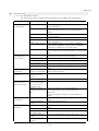
7-2.Troubl eshoot i ng
Si mpl e t roubl eshoot ing procedures agai nst proble ms in comm uni cati on wi th C remot e SOTs
are show n below .
For p robl em s rel ated wi t h C PU uni ts and mast er/ slave uni ts, see t he
relevant user's manual .
7-2-1.Troubl eshoot i ng f l ow
A p robl em occurs.
Is RCV l amp
( green ) on C
rem ote SO T off?
See the fl ow again st RCV lamp ( gree n )
bein g off.
Is RUN lamp on
m as ter unit off?
See User's Manu al fo r CC -Li nk
Syst em Mast er/L ocal Uni t .
Is RD/S D la mp on
m aste r u nit off or
c ontin uous ly li t?
Do es an y s tation
b eco me fa ulty a t
c ertain baud ra tes?
Ch eck for cab le wirings long er than
spe cifi ed and f or c onfu sed cab les.
Ch eck that te rm ina l re gist ers are
prov ided a nd const ant s are correct .
See th e flow aga inst i mpos si ble da ta
ex cha nge.
- 28 -
DS4-2156
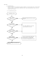
7-2-2.I f t he RC V l amp ( Green ) is of f
I s RCV la mp
( green ) on C re mote
SO T off?
Is the oth er
SO T po we red?
Is optic al ax is
c orrec tly lo cate d?
I s CTL ( TC D ) f un ct io n ,
if provided with theother
SO T, of f?
Does the
situat ion remain the
same if the ot her SOT is
replaced with
another one?
Power the oth er SOT.
Re loc ate op tica l a xis so th at RCV
lam ps on b oth SO Ts will tu rn on.
Turn CTL ( TCD ) fu ncti on off.
CTL f unction: Optical transfer stop function
TCD function: OPtical tr ansmission stop function
The oth er SOT is faul ty.
Pleas e return it to u s with de tailed
des cripti on of prob lem .
C rem ote SO T is faulty .
Contac t our sa les o ffice o r Sa les
Engin eerin g Sect., El ectron ics Di v.,
Kagiy a Fac tory .
- 29 -
DS4-2156
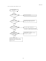
7-2-3.I f da ta cannot be excha nged
Troubleshooting f low
against impossible data
exchange
I s the same
baud r ate used by
master st at ion and C
remot e SOT ?
Spec ify th e sam e bau d rate for
mas ter sta tion an d C rem ote SO T.
I s sta t ion
N o. of C remote SOT
correct?
Spec ify c orrect s tation No .
・ Spec ify a No. be tween 1 a nd 64.
・ Do not us e the s ame s tatio n No.
more th an onc e.
I s total
number of remote
st at ions correct?
For total n umb er o f re mote stati ons ,
spe cify the larg est s tation No . o f
con nec ted rem ote un its ( incl udin g
occ upi ed sta tions ) .
Are any
error code st ored in
link regist er?
Tak e correc tive acti on aga ins t e rro r
cod e.
Spe cifi ed as
rese rv ed s tation ?
I s remote
station information
wr it ten at parameter
set tings?
Ca nce l the s pec ifica tion a s
re se rv ed s tation .
Write rem ote st ation in forma tion.
See th e flow aga inst
i mpo ssi ble rec eptio n
Is da ta rece ived ?
Is t ra nsm iss ion
stop input o ff?
Turn trans mis si on sto p inp ut off.
Conta ct our s ales o ffice or S ales
Engi neerin g Sect ., El ectro nics Div.,
Kagi ya Fa ctory .
- 30 -
DS4-2156
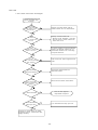
7-2-4.I n case o f im possi ble recept ion
Troubleshooting f low
against
impossiblereception
Are I /O signals
r ead by sequence
program?
Add I/O sig nal read ing
program .
Is data read from
correct addr ess?
Ch ang e to correc t add re ss .
Contact our sales off ice or Sales
Engineering Sect. , Electronics D iv.,
Kagiya F act or y.
- 31 -
DS4-2156
8. Mai nte nance and I nspect i on
The SOT-CP 160 1 seri es product s should be serviced accordin g t o the f oll owi ng schedul e.
The check f requency is onl y show n f or your ref erence and shoul d be chan ged i n
consi dera ti on of t he con dit i ons of use a nd envi ronme ntal condit i ons.
Caution:
W hen servi cing , t ake ad equat e saf et y m easures so t hat no equi pm ent
around t he uni t w il l not a ccident al ly move .
C heck i t em
Descript i on
C heck
f requency
Cl ean opt ical a xis
W ip e out transm it t er/recept or op ening
Every 3
surfa ce.
surf ace w it h sof t clo th.
m onths
Do not use any
sol vent such as pain t t hinne r and alcoh ol.
Cl ean name plat e.
W ip e out name plat e wi th sof t cl oth so tha t
i t reads clearl y.
Do not u se any sol vent
such as pain t th inner and alcoho l.
I f nam epl at e i s pe eled of f or b ecomes
i ll egi ble , replace wi t h a new one ( suppl ie d
at your cost ) .
Che ck com muni cat ion
D ete rm ine t he rang e w here R CV lam p on
range.
m ain body l ight s to check for opt ical a xi s
shi f t.
Che ck f or l oose
C heck ea ch part of mai n body f or loose
screws.
screws.
Che ck cabl es.
C heck cab les and connect ors f or dam age.
- 32 -
DS4-2156
9. Speci fi cat ions
9-1.C C-Lin k speci fi cat ion s
I t em
Speci fi cat ion
Appl i cable sequence r
M ELSE C A/Q nA/ Q series, Mi tsubi shi El ect ric
App lica ble m aste r u nit
A J61BT11, A1SJ6 1BT1, AJ61Q BT11, A1SJ61Q BT11, QJ61 BT11
Com mu nicat i on
C ont rol & C omm uni cati on L ink (CC-Li nk)
m etho d
No. of occupi ed
st ati ons
1
Transf er rout e
B us
Transf er f ormat
H DLC
Lin k c onne cting mea ns
C onnect or t ermi nal bl ock ( M STB 2. 5/ 5-S T-5. 08, Phoeni x C ont act )
Con necti ng cabl e
C C-Lin k dedi cat ed ca ble
M axim um t ransf er
di stan ce
12 00 t o 100 m ( dependi ng on ba ud rat e )
Baud rat e
10 M , 5 M, 2. 5 M, 625 K or 156 Kpbs
9-2.O pti cal t ransf er speci fi cat ions
I t em
Speci fi cat ion
M odel
S OT-CP16 01H
SOT -C P1601S
S OT-CP16 03H
SOT -C P1603S
Opt i cal axi s di recti on
H ead-on
Si de-on
H ead-on
Si de-on
Rat ed vol tage
D C24V
Ope rat i ng vo lt age
D C 18-30 V
Current con sumpt io n
15 0mA MA X
Transf er di sta nce
0 t o 1 m ( wi t h l i ght i nte nsit y
cont rol knob set t o MAX )
0 t o 3 m ( wi t h l i ght i nte nsit y
cont rol knob set t o MAX )
Em it t ing di re cti on
30 degrees or m ore
( at 1 m d ist ance )
5 degrees or m ore
( at 3 m d ist ance )
Transf er m etho d
S emi -d ual bi -di recti onal o r uni -di recti onal
Det ect i on m et hod
C ont inuou s m onit orin g of bit stat us changes
Transf er t im e
20 m s m ax. ( i n M /S m ode ) or 30 m s m ax. ( i n X m ode )
Proj ector ele ment
N ear i nf rared li ght e mi tt i ng di ode
Rece iver e lem ent
P hoto -t ransist or
No. of t ransfe r bit s
15 ( 16 ) i nput bi t s and 15 ( 16 ) out put b it s
( 16t h bi ts may be swi tched t o control i nput / out put )
No. of cont rol i nput s
1 ( CTL /TC D ) ( wi t h D SW3 of f )
No. of cont rol out put s
1 ( RC V )
Sw it ches
① S tat i on N o. sel ect swi t ches ( 2 rot ary swi t ch es )
② B aud rat e select swit ch ( a rot ary sw it ch )
③ M ode select swi tches ( di p sw it ches )
I ndica tor lam ps
( wi th DS W3 of f )
P OW l amp:
Li ght s ( red ) wi t h po wer supp ly on.
C TL/ TCD l amp: Li ght s ( red ) wi t h C TL i nput on.
Li ght s ( green ) w it h TCD i nput on.
D T/ RC V lam p: Li ght s ( red ) whe n dat a is normal l y recei ved.
Li ght s ( green ) duri ng st abi li zed recepti on.
I N l amp:
Li ght s ( red ) wi t h rel evant opt i cal out put da ta on.
O UT lam p:
Li ght s ( green ) w it h rel evant o pti cal i nput dat a on.
R UN l amp:
Li ght s ( green ) duri ng n orm al dat a exchange wi th
m aster uni t.
E RR la mp:
Li ght s ( red ) wi t h da ta erro r received and t urns of f
duri ng no rm al com muni cat ion.
S D lam p:
Li ght s ( red ) durin g l in ke d dat a t ransm issi on.
R D lam p:
Li ght s ( red ) durin g l in ke d dat a recept ion.
- 33 -
DS4-2156
I t em
Speci fi cat ion
Ope rat i ng a mbi ent
t empe rat ure
-20 t o 50 deg C
( no co ndensat ion al low ed duri ng operat ion )
Ope rat i ng a mbi ent
hum idi t y
40 t o 85%R H
( n o cond ensati on all ow ed )
Ope rat i ng a mbi ent
i ll umi nance
4, 000 Lx or l ess
Vi brati on re sist ance
10 t o 55Hz, 1. 5m m dual am pli t ude 2 hou rs each in X, Y and Z
di recti ons
I mpact resi st ance
50 0 m /s 2 ( app rox. 50G ) ,
( no di sturbi ng rays shoul d di rect ly ent er receiver )
2 h ours each in X, Y a nd Z di rect i ons
Prot ect ion cla ss
I P40
Pow er suppl y
connect i on
C onnect or t ermi nal bl ock ( M STB 2. 5/ 2-S T-5. 08, Phoeni x C ont act )
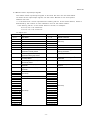
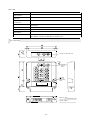
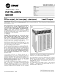
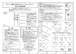
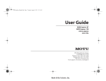
Ph ysica l dimen sion s
9 0 ㎜ (W)×80 ㎜ (D)×20 ㎜ (H)
( f or de tai l , see the schem ati c in sect ion 10 )
10. Schem ati c
Cen ter o f optic al ax is
Cent er o f
op tica l
ax is
M ount ing
ho le
Material: ABS
( U L inflammable resin )
C olor: B lue
- 34 -
DS4-2156
11. Set ti ngs and Pro cedure
11-1.G uarant ee pe ri od
An year af t er del ivery to t he specif i ed l ocat ion
11-2.S cope of Guarant ee
If any part of t he prod uct i s f ound to have a fau lt at t ribut abl e to us duri ng t he gua rant ee
period as def ined above, it wil l be repla ced or rep aired at our cost.
Thi s does not a pply when:
① th e product has bee n i ncorre ct l y ha ndled or u sed by t he u se r,
② th e f aul t was caused f or a rea son not re lat ed wi th t he prod uct,
③ th e product has bee n al t ere d or rep aired by t he t hird part y, o r
④ th e f aul t was caused by a nat ural di sast er or an othe r accid ent unavoi dabl e b y us.
We onl y g uara ntee t he prod uct it sel f and t ake n o responsi bil i ty f or any secondary d amage
re sult i ng f rom t he use of t he product .
12. Revi sion Hi st ory
D ate
Cont ent of change
Resp onsibi l it y
Aug. 2000
Fi rst i ssue
Deve lopm ent
Sep. 2000
Q seri es ad ded, revisi on 'A'
Deve lopm ent
- 35 -