1
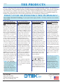
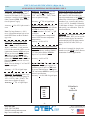
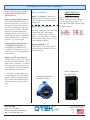
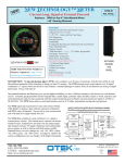
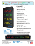
NEW NEW TECHNOLOGY™ METER NTM-0 Current Loop, Signal or External Powered Replaces: Any 1⁄8 DIN D.P.M. or A.P. M. Note: See model NTM-B for vertical 1/8 DIN display. FEATURES: *Automatic Tricolor Bar with Intensity Control *4 Digits (9.9.9.9 or -1.9.9.9) *Alarm with Run Time Stamp *Self Diagnostics *Isolated Serial I/O *USB/RS485 *Configurable Bar Direction (Up/Down/Center Zero)/ Pointer *Only 100mW@5VDC! *Intensity Control * Math functions (+, -, x, √, ÷, X-Y tables, polynomials) *Averaging: None to 255 *Addressable: 8 Characters *Many Power Input Options (External Powered Models Only) * >30 Isolated Input Signals *4 Relays or O.C.T. *4-20mA/30V Output *Ethernet *μSD Flash Memory: 32 GB *Lifetime Warranty Build Your Own Part Number/User’s Manual or Receive a Quote at: http://www.otekcorp.com/ configurator/nts/ DESCRIPTION: The New Technology Meter (NTM) series combines over 40 years of experience with the latest ASIC uC and ultra-efficient multicolor LED technology to bring you into the 21st century. The NTM external power series features over 30 signal conditioners (1” square) which are housed in many industry's standard packages to replace form, fit and function any analog or digital panel meter. If not, we'll make it! Our patented hardware and firmware gives you the highest reliability (we have a lifetime warranty) at the lowest cost, with features such as: automatic (programmable) tricolor bargraph (like a traffic light); automatic signal fail detect (open or short); indication and serial transmission with run time stamp and units ID, isolated retransmission (4-20mA), and universal power inputs (5-32VDC or 90-265VAC). The NTM Series offers several math functions such as X-Y tables, polynomials and log-anti-log functions. NEW TECHNOLOGY METER BLOCK DIAGRAM/CHANNEL The NTM signal and external power series also feature isolated USB, RS485 or ethernet, open collector transistors (4/channel) and SPDT relays (4/channel). You can tell us your custom needs and we'll make it (or might already have it)! The NTM-0 is available in either a loop (4-20mA), A.C. signal or external power version. The external powered versions can accommodate 4 relays, isolated DAC and power for the analog output (per channel), include >30 signal conditioners and isolated input power options, as well as ethernet and flash memory (μSD). Standard factory set color changes are: red: <10, >90%, yellow: <20, >80%, green: >20, <80% of F.S. Use digit 14, option 9 for custom configuration (you can change it with simple commands). 520-748-7900 FAX: 520-790-2808 E-MAIL:[email protected] http://www.otekcorp.com CONTROLLER/DISPLAY ONLY I V IN A IN CURRENT LOOP (LOOP POWER) AC/DC V, A,W, Hz (SIGNAL POWER) • DISPLAYS, CPU, SIGNAL DETECT, KEEP ALIVE, ISOLATORS FOR ALARMS, SERIAL I/O, PWM, ZERO/SPAN SIGNAL CONDITIONERS REL AYS O.C.T ANALOG OUT ETHERNET USB/485 FLASH MEMORY O.C. T. (4) RELAYS (4) 4-20mA OUT (1) 30V OUT (1) RS485 USB/ ETHERNET RS 485 (EXTERNAL POWER) USB 5-32 VDC 90-265 VAC POWER SUPPLY POWER INPUT DISPLAY ONLY 4016 E. TENNESSEE ST. TUCSON, AZ. 85714 U.S.A. SINCE 1974 MADE IN USA NTM-0 THE PRODUCTS All New Technology products share the same innovations proven by an independent NQA1 qualifier. The difference between the models is their mechanical features (see Block Diagram and mechanical drawings). Some can only be displays, some can only have 1 channel, some can have relays, DACs, ethernet and flash memory, and some require an external power source. But all products contain the New Technology, which consumes less than 1% of comparable digitals (1080mW for loop/signal powered versions) and approaches the power consumption of analog meters. WHAT CAN YOU DO WITH OTEK’S NEW TECHNOLOGY? Note on Otek’s Powerless™ Technology: If your signal cannot supply mW (~ 3V/3mA), contact us or use external power models. 1. One Channel Models: -0, -4, -B, -D, -F, -L, -M, -N, -P, -S & -X: Implement any math function, X-Y table (25 point), polynomials (9th order), offset, tare, zero, scale, log & antilogarithmic to affect the unit’s display at will. Some examples are: change the display & data using any combination as commanded by your algorithm, such as +/-/X/÷/√ or set a variable or linearize the display using X-Y tables or polynomials. This works well for odd shape containers. You can also change the reading from ◦F to ◦C or ◦K or compress/expand the display (and data out) using the log and antilog functions. In addition, you can change the factory default alarm pointers and colors or delete them. Zero & Span potentiometers are included for manual adjustment. Note: Models -D and -F only offer internally accessible USB serial I/O for configuration and mathematical functions. Use digit 14 option 9 and specify your custom calibration. OTEK’s New Technology series is only limited by your needs and imagination. Just give us a call at 520-7487900 or email us at sales@ otekcorp.com and give us the challenge to develop the best algorithm for your process. 2. Two Channel Models: -1, -2, -3 and -5 through -9 & -A: Note: Also available in models with 3 or 4 channels. Features include all those of the single channel models and each channel is 100% isolated from each other. In addition, you can add, subtract, multiply, divide, find the square root between channels. You can also use one channel to monitor/control the input signal and the second channel to indicate deviation, differential such as PID, alarm override or one channel setpoint can be used to control another channel function. You can also use one channel as a backup if the other channel becomes disabled or use them as volume & flow (√) monitors/ controllers. The New Technology two channel models are also perfect as REM/RAD indicators/controllers (also see our RPM series with logantilog functions for radiation monitoring). Contact OTEK for algorithms and formulas or any idea you wish to share with our audiences via our Youtube or Facebook page posts. 3. Three Channel Models: -3, -5, -7, -8 and -A: Note: Also available on 4 channel models -5, -7 & -8. Otek’s New Technology three channel models perform all the functions outlined in #1 and #2. Further, one channel can indicate the input variable and the other two channels can be setpoint indicators/controllers (Hi, Hi-Hi, Low and Low-Low limits), or subject the input/ output to any mathematical function or algorithm such as PID or display the input vs. output and derivative, or switch scales when the input reaches a limit/band such as for flow-volume-pressure or temperature. Monitor Volts, Amps and Watts AC or DC or any of 3 variables, including Hertz, lead/lag, power factor, peak/valley or for synchronizing of power lines with the bipolar (center zero) tricolor bargraph. The New Technology series brings Process Automation Control (PAC) within your reach and affordability. These models are compatible with any DCS/SCADA system using their USB/RS485/Ethernet I/O options and allow for ease of interface with wireless systems. 4. Four Channel Models: -5, -7 and -8: The four channel models offer all of the functions outlined in #1, #2 and #3. However, with the additional channel available, the New Technology barmeters rival flatscreens with superior HMI/MMI functionality and ease of viewing/analysis of any combination of 4 variables. For example, Volts/ Amps/Watts/Hertz or temperature/pressure/pH/humidity. The four channel models can also be used to monitor/control the product of the other 3 variables, making them ideal for the petrochemical industry. Data Logging? Some models offer optional μSD memory to record 24/7 anything available via the serial I/O. Maximum capacity (and growing) is 32 GB! REDUNDANT CONTROL: Because all channels are 100% isolated from each other, you can use any multi-channels model as a redundant controller. If you need the “Democratic vote,” algorithm, contact OTEK or see our Model TRC (Triple Redundant Controller). -2520-748-7900 FAX: 520-790-2808 E-MAIL:[email protected] http://www.otekcorp.com 4016 E. TENNESSEE ST. TUCSON, AZ. 85714 U.S.A. SINCE 1974 MADE IN USA NTM-0 Description, Notes & Order (Continued) Digit 5, Serial I/O & Memory: Settings: 8N1N, 1200-19,200 Baud, ASCII. LOOP/SIGNAL POWER ONLY: Digit 5, Serial I/O: Option 0, USB: Complies 100% with V2.0 and if digit 10, option 1 is selected (USB powered) then digit 5 must be option 0. Digit 5, Option 1, RS485: Complies with industry standard and requires 5VDC@<3mA and a terminating 330 Ohm resistor at first and last unit in the BUS. EXTERNAL POWER ONLY: Digit 5, Option 2 Ethernet: Complies with 10 Base-T/100Base-TX RJ45 up to 19,200 Baud. Maximum power consumption is <300mA@5V (1.5W). DIGIT 6, GRADE: Industrial Grade (Options 0 or I) is per these published specifications. Grades M and E per agreed specifications. Option M & E typically include an EMI/ RFI shield all around and filtered connectors to meet EPRI-TR-102323-R3 (requiring ~2” deeper case). OTEK will build to certain nuclear or MILStandards but testing and confirmation of compliance, if required, will need to be done by third party and at customer’s expense. Option 0 is 94VO plastic, option “I” is aluminium nickel plated to Mil-Specs. Typical Mil-Specs: 461, 462, 169, 901, 801, RTCA-160, I EEE344, etc. Other Important Data: Math Functions: +, -, x, ÷, √, Polynomials to 9th order, 25 Point X-Y table, Digit 5, Options 3 & 4: uSD Flash zero, offset, span and tare. You can Memory: Internal μSD flash memory add, subtract, multiply, divide (etc.) one with up to 32 gigabytes capacity. You channel to/from another channel and can store selected data at-will via serial display the result in the other channel command and download it as required. (i.e. V (Ch.1)xA(Ch.2)=W(Ch.3). A 32 GB card logging 3 times per second can hold approximately 4 year’s Signal Failure Alarm: Requires apworth of data. proximately 1 minute of normal (midscale) operation for it to alarm the display and output the serial data after Need a Transmitter? the signal (Powerless™) has ceased. See model TNT Serial I/O: Setting: 8N1N, 1200-19,200 BAUD, 8 Character Address PID: Programmable (best with >dual channel models) automatic or manual with external 10K Ohm potentiometer (option 56). Other Important Data: (Continued): High Quality: No matter their size or number of channels all use the same (SV & V) firmware, hardware and commands. No matter their grade (Industrial, Mil-Spec, Nuclear) they all carry a lifetime warranty Industrial Grade Common Electrical Specifications Input & Display: *A/D: Accuracy, Linearity & Resolution: +/- 0.05% of F.S. 12 Bits, Conversion Rate: 40/sec, Averaging: 0-255, zero, span, offset, tare, math functions, 25 point X-Y tables & polynomials (9th) *Bargraph: 51 Automatic Tricolor (R/Y/G) Segments *Digits: Four Full Digits (9.9.9.9 & -1.9.9.9). *Typical Power Consumption of Display: [email protected] *Temperature Coefficient: +/-50PPM/°C *Operating Temperature: -10 to +60; Storage: -20 to +70°C *CCMR: >90dB@50-60Hz *Isolation: >500VDC to any other I/O & P.S. *Humidity: 5-95% RH non-condensing *Front Panel: NEMA 3. NEMA 4x on request. *Failed Signal Detect: ~ 20 seconds after > 1 minute “On” @50% of F.S. Note 1: See page 13 of the master catalog for environmental specs vs. housing, bar length and digit size. Note 2: E and M grades are the same as Industrial unless otherwise specified. -3520-748-7900 FAX: 520-790-2808 E-MAIL:[email protected] http://www.otekcorp.com 4016 E. TENNESSEE ST. TUCSON, AZ. 85714 U.S.A. SINCE 1974 MADE IN USA INPUT SIGNAL SPECIFICATIONS (Digits 8 & 9) Industrial Grade Common Electrical Specifications (Continued) AVAILABLE ON EXTERNAL POWER MODELS ONLY: Outputs: *Analog Output: Accuracy & Linearity: F.S.; 0.1 LSB, Range: 3-24mA (max. load: <1K Ohm). *Analog Output Temperature Coefficient: +/-50PPM°C *Analog Output Isolation To All Other I/O & Power: >500VDC *Relays: 4 Each/Channel (except P and TNT {2}): SPDT Form C, 1A Max @ 120VAC/30VDC resistive load only, Contact Protection: 300VAC/DC on all contacts. Speed: +40mS (main loop). O.C.T. (Open Collector Transistors): VCE Max: 30VDC; Ice Max: 30mADC, Speed: +40mS (main loop). Note 1: Relays & O.C.T. P.O.D. (~100 mS) and can be set for fail safe operation (normally on). Note 2: See Digit 11 for default set points and User’s Manual for command set via serial control. SEE CUSTOMIZED USER’S MANUAL FOR SPECIFIC CONNECTIONS AT: http://www.otekcorp.com/ configurator/nts/ INPUT SIGNALS (Digits 8 & 9): Option 04, Hertz VAC: Burden: Note: Otek’s exclusive Input Fail <100mW, Range: >30V<150V & detect (open or short) is standard on all >30<500Hz; Accuracy & Linearity: inputs. Use option 29 and specify if ±0.2% of F.S. you want it disabled (also field configu- Option 05-14: Same as options 01 rable). through 04 above. Important Note: Actual connection will vary. See the User’s Manual or AVAILABLE ON EXTERNAL the NT Catalog for specific connection POWER ONLY information. Option 00 For Loop Power Only: Option 00, Loop Powered: Burden: < 4V; Range: 3-26mA; Accuracy & Linearity: ±0.05% of F.S. Options 01 through 14 for A. C. Signal Powered Only Option 20: 4-20mA: The burden on the loop is only 0.5V@20mA (25 Ohm) and you can use the math functions for converting to flow, instantaneous or totalizer. Accuracy: +0.1% of F.S. Options 21-24: VDC: Input impedance is 1 Mega Ohms on all VDC Important Note: C.T. are sensitive and ranges. limited to the secondary (output) impedance. OTEK A.C. signal powered Input impedance 1M Ω products present and input impedance Range: Per Option of ~0.2 Ohms (~1v@5A). Make sure Accuracy & Linearity: ±0.05% of F.S. your C.T. can drive a >0.3 Ohm load without saturating or losing linearity. Options 25 & 26, mADC: Since the Contact Otek for assistance. Best C.T. NTM is 2V full scale (2,000 Counts) to use: >100:5. the “Shunt” resistors used are 100 Ohms for 10mA and 10 Ohms for Option 01, VAC (P.T.): Burden: 100mADC. <100mW; Range: 30-150V/40-100Hz; Accuracy & Linearity: ±0.2% of F.S. Input impedance 25: 50Ω; 26: 5Ω; Best operating range to specification: Accuracy & Linearity: ±0.05% of F.S. 90-150VAC. Option 27, Watts DC: Option 02, 5 AMP A.C. (C.T.): BurVZin: 10M Ω/AZin: 1.0Ω, 5W den: <100mW; Range: .3-5A; AccuRange: 1W racy & Linearity: ±0.2% of F.S. Best Accuracy & Linearity: ±0.1% of F.S. operating range to specification: 1-5 Amps. Option 03, Watts A.C. (C.T. & Option 28, Watts DC (1Vx1V): P.T.): Burden: <100mW, Range: VZin: 1M for both inputs >30<750W/50-60Hz; Accuracy & Lin- Range: 0-1V earity: ±0.2% of F.S. at 90-140VAC & Accuracy & Linearity: ±0.1% of F.S 1-5AAC. Worst case: ±3% outside this range. Best operating range to specification: 100-500 Watts. -4- 520-748-7900 FAX: 520-790-2808 E-MAIL:[email protected] http://www.otekcorp.com 4016 E. TENNESSEE ST. TUCSON, AZ. 85714 U.S.A. SINCE 1974 MADE IN USA NTM-0 INPUT SIGNAL SPECIFICATIONS (Digits 8 & 9) AVAILABLE ON EXTERNAL POWER MODELS ONLY Option 29: Custom: Use this option to describe any custom input, scale or modification to the NTM and contact us for feasibility and cost. Options 30-34, Volts RMS: Here we use a True RMS-DC Converter for accurate (+ 0.1%) measurement of sine waves up to 10KHz. For 10-20KHz and SCR accuracy is + 1%. VRMS: Zin: 1MΩ Range; per options; Accuracy & Linearity: ±0.1% of F.S. Options 35-37, Amps RMS: We use a True RMS-DC Converter for accurate (+ 0.1%) measurement of sine waves up to 10KHz. For 10-20KHz and SCR accuracy is + 1%. Zin: 35 (1A): 2Ω; 36 (1A): 0.2Ω; 37: 0.(0.1A) 04Ω (Range: Per option Accuracy & Linearity: ±0.1% of F. S. Options 38 & 40, Watts RMS: Here we use a True RMS-DC Converter for accurate (+ 0.1%) measurement of sine waves up to 10KHz. For 10-20KHz and SCR accuracy is + 1%. Input impedances vs. range are the same as for VDC & mADC ranges. Option 38 (1Vx1VAC): Zin: 1MΩ for both inputs Range: 1V RMS Accuracy & Linearity: ±0.2% of F.S. Option 40 (120VACx5AAC C.T.): Zin: 1M for V & 0.04Ω for I Range: 0-750W Accuracy & Linearity: ±0.2% of F.S. Note: Option 40 (120V/5A) includes the shunt (0.04 Ohms/20W) on connector only for 5A C.T. Options 41-44, Hertz: We use an F-V to accept frequencies up to 20KHz and amplitudes from 1-400V peak or dry contact or open collector transistor (O.C.T.). For 50 to 440 Hz power line frequency measurement, use Option # “44.” Option 41 (10KHz/5V Logic): Zin: 1M Range: 30-10KHz Accuracy & Linearity: ±0.1% of F.S. Option 42 (120V, 40-100Hz): Zin: 1M Range: 50-150VC/30-100Hz Accuracy & Linearity: ±0.1% of F.S. Option 43 (240V, 30-100Hz): Zin 1 M; Range: 100-260V/30-100Hz Accuracy & Linearity: ±0.1% of F.S. Option 44 (120V, 500 Hz): Zin: 1 M Range: 50-150V/300-500Hz Accuracy & Linearity: ±0.2% of F.S. Option 45: Strain-Gage (>300 < 4K Ohm): These are typically "Monolithic" S-G that require constant voltage (preferably) excitation. We use 4.096V for high stability and accuracy. Use option 29 and specify your S-G sensitivity and the NTM display at Zero and Full Scale. Excitation: 4.096V, 50 PPM/C Range: ±300-4K Ω Accuracy & Linearity: ±0.1% of F.S. Note on S-G: Some S-G offer +/1VDC or 4-20mA condition output. Use Option 29 and specify. Option 47: RTD (PT100): Note: For options 47 & 48 you can change °C to °F and RTD type via serial port. We excite your 2 , 3 or 4 wire RTD with 200μA to avoid the "self heating" effect. The range of the NTM is the same as your RTD typically -2000C to +8000C (-328 + 15620F). You can place the decimal point at will (typically -200.0 to 800.0. The PT100 has a temperature coefficient of 0.00385 Ohms/Ohm/0C. (For legacy 0.00392 TC (known as ANSI 392) contact OTEK and use Option "29". Accuracy: +0.5% of F.S. plus sensor's error. Note: For 2 wire, jump - S to -E and +S to +E. For 3 wire only jump -S to -E. Note: Always use P.T. & C.T. for options 33, 34, 40, 42, 43 and 44. -5520-748-7900 FAX: 520-790-2808 E-MAIL:[email protected] http://www.otekcorp.com 4016 E. TENNESSEE ST. TUCSON, AZ. 85714 U.S.A. SINCE 1974 MADE IN USA NTM-0 INPUT SIGNAL SPECIFICATIONS (Digits 8 & 9) AVAILABLE ON EXTERNAL POWER MODELS ONLY Option 48: RTD (PT1000): Same as PT100 except it is 1000 Ohms at 00C instead of 100 Ohms @ 00C. The same technique is used for copper RTD (10 Ohm), contact OTEK. Same connection as Option 47 apply. Option 52: TC (Type T): This blue (+) and red (-) TC has the range of -2700 + 4000C (-440 + 7500F). Same notes as Option 50 apply. Accuracy: +0.5% of F.S. plus sensor's error. Option 53: pH (Acidity): We use a FET input (1015) amplifier and calibrate the NTM for 0-14.00 pH using the Industry's standard + 413 mV = + 7pH co-efficient. Note: Not temperature compensated, contact OTEK for auto temperature compensation. Accuracy: +0.05% of F.S. Note: For long distances (> 300’) use a 4-20mA transmitter such as our model TNT from our New Technology series. Option 50: Thermocouple (Type J): This TC has a range of -210 to + 7600C (-350 + 13900F). Its color is white (+) and Red (-), cold junction (CJ) is at the connector. Make sure the connections from the NTM and your TC are as close to the NTM entrance as possible to avoid errors. If you short out the NTM's +TC & -TC together, the NTM will read the ambient temperature at the junction due to its built-in C.J.C. Note: You can change °C to F and TC type via serial port. Accuracy: + 20 F.S. of signal input. Option 51: TC (Type K): This is yellow (+) and red (-) and has a range of -270 + 13700C (-440 + 25000F). The same notes as Option 50 apply. Accuracy: + 10 F.S. of signal input Accuracy: + 20 F.S. of signal input. Option 54: ORP (Oxygen Reduction Potential): Our FET amplifier (109) accepts the industry standard 2000mV F.S. of the probe and the NTM displays it in % (0-100.0%). Option 56 Resistance (0-10K Ohm): Want a simple 4-20mA transmitter? Just connect a 10K Ohm (others on request) potentiometer to the NTM and control any 4-20mA input valve, motor, transducer, etc. Accuracy & Linearity is ±0.1% of F. S. Standard Calibration: 0-10K Ohms=4-20mA. Use option #29 and specify your calibration. Ideal for linear transducers. Option 58: Serial Input Remote Display/Controller: Here you can use the unit as a remote display & controller with modified ASCII to alpha-numeric display for DCS SCADA, PLC systems. See the user’s manual for simple commands to use the NTM in PAC (Process Automation Control) applications. Accuracy: +0.05% of F.S. Option 55: %RH: This conditioner is designed to interface to a typical (capacitance type) 2-3pF/% of RH made by several manufacturers. Use Option "29" and contact OTEK to specify your sensor's specifications. Accuracy: + 0.05% RH of signal input. Need the Transmitter? NTT DRT CTT TNT If You Don't See It Ask For It! -6520-748-7900 FAX: 520-790-2808 E-MAIL:[email protected] http://www.otekcorp.com 4016 E. TENNESSEE ST. TUCSON, AZ. 85714 U.S.A. SINCE 1974 MADE IN USA NTM-0 Description, Notes & Order (Continued) Digit 10 (Power Input): Digit 11 (Control Outputs): LOOP & SIGNAL POWER ONLY: Digit 10, Option 0, Powerless, No Power Required: The Input Fail detect/Alarm (patent pending) flashes the display “INPT FAIL” ( )” and transmits this serial message for ~20 seconds, after which it will cease. This feature is available in all Powerless™ models. If desired, use option 9 on Digit 14 and specify “input fail detection.” Signal Fail Requirement: Unit must be “On” for at least 1 minute at >50% of full scale for it to operate. AVAILABLE ON EXTERNAL POWER ONLY EXTERNAL POWER ONLY: Digit 10, Option 1, USB Powered: The NTM series requires >.1<1.5 Watts/Channel (worst case, fully loaded) meaning that you can power it through the USB port, but this option eliminates the isolation from USB to input signal. Analog output remains isolated contact OTEK for more details or use options 2-4. Digit 10, Option 2, 5VDC: 5VDC is used to drive the relays (<50mA/ relay) and/or the DAC via internal isolated 5-30VDC-DC (<200mA). If you order relays and analog out, you will need ~300mA/channel. This option is also isolated from the input signal. Digit 10, Option 3, 7-32VDC: Same as option 2 but with wide input range of 7-32VDC. Efficiency: >80%. Digit 10, Option 4, 90-265VAC: This option accepts 50-60Hz. For 100-300VDC or 400 Hz, use Digit 10, option 9 and specify. Efficiency: >80%. Digit 11, Control Outputs: Option 1: Open Collector Transistors (O.C.T.): They are NOT isolated from each other (common emitter) but are isolated between channels and can sink a maximum of 30 mA and sustain a maximum of 30VCE (the O.C.T. are normally used to drive S.S.R.). When you order option 2 (Relays), we use the O.C.T. to drive the relays. Digit 11 (Control Outputs): (Continued) Safe Area (>20<80%): Green bar will follow signal input and if outside the limits, it will change its color to the limit’s color (yellow or red). See commands in the user’s manual to customize your bargraph colors. For other configurations, use option 9 on Digit 14 (field configurable). Max power consumption per relay: 50mA@5VDC (0.25W). See Digit 14. NOTE: You can use the internal isolated 5VDC power to drive loads with the O.C.T. Total maximum current available is 50mADC. External Control: You can control the O.C.T./Relays via the serial port at will with simple commands. They don’t have to be assigned to the bar colors/set points, but are by default. Digit 11, Option 2: Relays: are S.P.D.T. (1C) and can switch maximum resistive loads of 1 Amp @ 120 VAC or 30 VDC. They include 300V varistors at their contacts; inductive loads must be attenuated by the user. Notes: 1. Digit 11 is governed by Digit 7 (# of Channels) & Digit 4 (Housing). Reason: Digit 11 can NOT have more channels than permitted by Digit 7 or it cannot fit in the housing (Digit 4). AUTOMATIC BAR COLORS: Limits/Colors Factory default (% of Full Scale): Also see digit 14. Low-Low Limit (<10%): Red Bar, OCT1/K1 “ON” Low Limit (<20%): Yellow Bar, OCT2/K2 “ON” High Limit (>80%): Yellow Bar, OCT3/K3 “ON” Note: Some models only offer 2 relays (see the ordering information). You can assign any relay to any limit. SEE CUSTOMIZED USER’S MANUAL FOR SPECIFIC CONNECTIONS at: http://www.otekcorp.com/configurator/nts/ Hi-Hi Limit (>90%): Red Bar, OCT4/ K4 “ON” -7520-748-7900 FAX: 520-790-2808 E-MAIL:[email protected] http://www.otekcorp.com 4016 E. TENNESSEE ST. TUCSON, AZ. 85714 U.S.A. SINCE 1974 MADE IN USA NTM-0 Description, Notes & Order (Continued) Digit 12 (Analog /Power Output): AVAILABLE ON EXTERNAL POWER ONLY Digit 12, Analog Output, Option 1: This isolated output is factory set to follow the input (0-F.S. in=4-20 out) but can also be set for other outputs or serially controlled by simple commands via the serial port. For other outputs, use option 9 and specify, including reverse scale (4-20=20-4), bipolar and PID. Power consumption: 200mA@5VDC (1W). Accuracy & Linearity: ±0.5% of full scale. Analog Output External Control (Use Option 9 and specify): A) 0-100mVDC in=4-20mA out; B) 0-10K Ohm in=4-20mA out; C) Use options 58, 68, 78 or 88 and control it via serial port. Digit 13 (Scale Plate): Digit 13, Scale Plate: Option 0 is a standard scale plate that reads 0-100%. Use option 9 for custom printing and contact Otek. Digit 14 (Range/Calibration): ABOUT OUR INPUT FAIL DETECTION Only available on Powerless™ models. While in normal operation, we store excess energy and use it to power the NTM if and when the signal fails (post mortem). 0= Factory Default: 0-Full Scale Input =0-100% bar and 0-100.0 digits. Colors: <10>90%: Red; <20>80%: Yellow; >20<80%: Green. Use Option 9 (custom) and contact Otek. Also see Control Outputs (Digit 11). Bargraph Default: 0-full scale=0-100%. You can program it for single pointer, or three or five bars via the serial port. Digit 12, 30 VDC Out, Option 2: Use this option to power your 4-20mA transmitter or other transducer. Maximum current is 25mADC. It’s isolated and is the same power source we use for 4-20mA out. Power consumption: 200mA@5VDC (1W)/channel. 1. This digit 12 is governed by digits 4 (Housing) & 7 (# of Channels). Reason: Digit 12 cannot have more outputs than input channels (Digit 7), which is governed by Digit 4 (Housings). Need Explosion Proof? See Model NTM-X Need a Transmitter? See model NTT -8520-748-7900 FAX: 520-790-2808 E-MAIL:[email protected] http://www.otekcorp.com 4016 E. TENNESSEE ST. TUCSON, AZ. 85714 U.S.A. SINCE 1974 MADE IN USA NTM-0 LOOP POWER VERSION ORDERING INFORMATION 5-18-15 1 CHANNEL LOOP POWERED DISPLAY NOTES: NTM-0 1. USB I/O is powered by VUSB. OTEKS SPM/BDM 1/8 DIN Case RS485 requires 5V@~3mA. 2. Otek will build to certain nuclear or MIL-Standards but testing and confirmation of compliance, if 5 6 7 8 9 10 11 12 13 14 required, will need to be done by - 0 0 0 -0 0 NTM-0 a third party and at customer’s RANGE/CALIBRATION SERIAL I/O (1) expense. 0..................................Standard 0......................................USB 1...................................RS485 9.....Custom (Contact OTEK) 9........Custom (Contact OTEK) SCALE PLATE 0.................Standard (0-100%) 9.......Custom (Contact OTEK) GRADE & CASE (2)* 0.................................................Industrial & Plastic I...................................................Industrial & Metal M.................To Mil-Spec & Metal (Contact OTEK) E.............To Epri-Nuclear & Metal (Contact OTEK) 9........................................Custom (Contact OTEK) *Grades E, M & 9 might require an N.R.E. fee. ANALOG/POWER OUTPUT 0..........................................None CONTROL OUTPUTS 0...........................................None # OF CHANNELS 1........................................One 9.......Custom (Contact OTEK) POWER INPUT 0..........Powerless™ (No Power) INPUT SIGNAL 00...........4-20mA, All Channels=Input, Loop Power NTM-0 SIGNAL POWER VERSION ORDERING INFORMATION 5-18-15 NOTES: 1. USB I/O is powered by VUSB. RS485 requires 5V@~3mA. 2. Otek will build to certain nuclear or MIL-Standards but testing and confirmation of compliance, if required, will need to be done by a third party and at customer’s expense. 3. For other ranges and inputs or powered versions, see the external power model. *Grades E, M & 9 might require an N.R.E. fee. 1 CHANNEL SIGNAL POWERED DISPLAY NTM-0 OTEKS SPM/BDM 1/8 DIN Case 5 6 7 NTM-0 - 8 9 10 0 - 11 12 13 14 0 0 RANGE/CALIBRATION 0..................................Standard 9........Custom (Contact OTEK) SERIAL I/O (1) 0......................................USB 1...................................RS485 9.....Custom (Contact OTEK) SCALE PLATE 0.................Standard (0-100%) 9.......Custom (Contact OTEK) GRADE & CASE (2)* 0.................................................Industrial & Plastic I...................................................Industrial & Metal M.................To Mil-Spec & Metal (Contact OTEK) E.............To Epri-Nuclear & Metal (Contact OTEK) 9........................................Custom (Contact OTEK) ANALOG/POWER OUTPUT 0..........................................None # OF CHANNELS 1........................................One 9.......Custom (Contact OTEK) INPUT SIGNAL (3) 01..............................................Volts A.C. 02..........................................5 Amps A.C. 03..............................................Watts A.C. 04.........................................Hertz A.C.V. 09.......................Custom (Contact OTEK CONTROL OUTPUTS 0...........................................None POWER INPUT 0..........Powerless™ (No Power) -9520-748-7900 FAX: 520-790-2808 E-MAIL:[email protected] http://www.otekcorp.com 4016 E. TENNESSEE ST. TUCSON, AZ. 85714 U.S.A. SINCE 1974 MADE IN USA NTM-0 EXTERNAL POWER VERSION ORDERING INFORMATION 5-18-15 NOTE: Please READ BEFORE building part number: 1. If digit 10 is option 1, then digit 5 must be option 0 or 3. USB I/O is powered by VBUS (3mA). RS485 requires 5V@~3mA. 1 CHANNEL EXTERNAL POWERED CONTROLLER 5 6 7 8 9 - NTM-0 10 11 12 - 13 14 RANGE/CALIBRATION 0..................................Standard 9........Custom (Contact OTEK) SERIAL I/O (1) 0............................................USB 1.........................................RS485 2......................................Ethernet 3................USB & μSD Memory 4.............RS485 & μSD Memory 9............Custom (Contact OTEK) SCALE PLATE 0.................Standard (0-100%) 9.......Custom (Contact OTEK) GRADE (2)* 0..........................................Industrial & Plastic I............................................Industrial & Metal M....To Mil-Spec & Metal (Contact OTEK) E.......To EPRI-Nuclear & Metal (Contact OTEK) 9...........................Custom (Contact OTEK) *Grades E, M & 9 might require an N.R.E. fee. NTM-0 OTEKS SPM/BDM 1/8 DIN Case ANALOG/POWER OUTPUT 0................................................None 1....CH. 1........................4-20mA Out 2....CH. 1..............................30V Out 9..................Custom (Contact OTEK) CONTROL OUTPUTS 0...........................................None 1....CH. 1.....................O.C.T. (4) 2....CH. 1.....................Relays (4) 9...........Custom (Contact OTEK) # OF CHANNELS (3) 1......................................One 9......Custom (Contact OTEK) INPUT SIGNAL (3) mAll Channels Same Input) 21...............................................100mV DC F.S. 22.......................................................1VDC F.S 23.....................................................10VDC F.S. 24..................................................100VDC F. S. 25.................................................10mADC F. S. 26................................................100mADC F.S. 27...................................Watts DC (1Vx1A) F.S. 28...................................Watts DC (1Vx1V) F.S. 29...............................Custom (Contact OTEK) 30...............................................0.1V RMS F. S. 31...................................................1V RMS F.S. 32.................................................10V RMS F.S. 33..............................................150V RMS F.S. 34.............................................250 V RMS F.S. 35...............................................0.1A RMS F.S. 36..................................................1A RMS F.S. 37...................................................5A RMS F.S. 38...............................W RMS (1Vx1VAC) F.S. 40..........................W RMS (120Vx5A AC) F. S. 41.........................Hertz (10KHz/5V Logic) F.S. 42....................Hertz (120VAC/40-100 Hz) F.S. 43...........................Hertz (240VAC/30-100 Hz) 44..........................Hertz (120VAC/500 Hz) F.S. 45........................Strain-Gage (≥300<4K Ohm) 47..................................................RTD (PT100) 48................................................RTD (PT1000) 50.....................................................TC (Type J) 51....................................................TC (Type K) 52....................................................TC (Type T) 53...................................................pH (0-14.00) 54.......................................ORP (0-2000mVDC) 55...................................% RH (Specify Sensor) 56......................................Resistance (0-10K None (Serial Input Remote Meter) POWER INPUT (1) 1......................Non-Isolated USB 2...........................Isolated 5VDC 3......................Isolated 7-32VDC 4...................Isolated 90-265VAC 9..........Custom (Contact OTEK) Build Your Own Part Number/Receive a Quote at: http://www.otekcorp.com/configurator/nts/ NOTES (Continued): 2. Otek will build to certain nuclear or MIL-Standards but testing and confirmation of compliance, if required, will need to be done by a third party and at customer’s expense. 3. For 400 Hz line, use option 29 and specify input. Peak & Hold to 50KHz function on request. -10520-748-7900 FAX: 520-790-2808 E-MAIL:[email protected] http://www.otekcorp.com 4016 E. TENNESSEE ST. TUCSON, AZ. 85714 U.S.A. SINCE 1974 MADE IN USA NTM-0 MECHANICALS AND TYPICAL CONNECTIONS SIDE FRONT 2.20 56mm 4.30” TO MOUNTING BRACKETS 48mm (1.9”) 96mm (3.78”) .2 .5 5mm 12mm PLUG IN SCREW CONNECTORS (16-26 GA WIRES) REAR 12 34 1 2 3 4 5 6 7 8 9 10 1112 12 SPAN ZERO ST1 USB SERIAL I/O 12 34 ST2 1 2 3 ST5 ST3 1.78 45.2mm DAC/30V OUT ST4 3.55 90.2mm Panel Cutout: 3.62”W x 1.85” H (92 x 46mm) Bezel: 3.78” W x 1.9” H (96 x 48mm) Wire: 26-16 GA. Connectors might vary with model. SEE CUSTOMIZED USER’S MANUAL FOR SPECIFIC CONNECTIONS at: http://www.otekcorp.com/configurator/nts/ DOWNLOADS: For manuals, user-software or drivers: www.otekcorp. com -11520-748-7900 FAX: 520-790-2808 E-MAIL:[email protected] http://www.otekcorp.com 4016 E. TENNESSEE ST. TUCSON, AZ. 85714 U.S.A. SINCE 1974 MADE IN USA