1
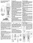
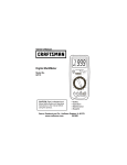
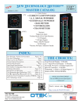
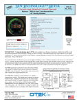
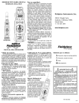
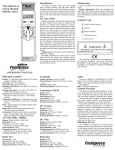
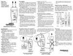
EXPANDABLE DATA LOGGER
MODEL: DL3
DL3 Data Logger
Clear button
The DL3 data logger records mV signals from any
Fieldpiece accessory head. It has an internal real
time clock. Program automatic recordings using
SPAN (the time over which measurements are made)
and PER (time period between measurements). The
new TRIGGER feature allows the DL3 to start and
stop recording points when the data is oustside of a
specified range thereby only recording the data that
is meaningful to you. Manually add single measurements by pressing record. You can readout the data
from the LCD screen using MIN/MAX/AVG and arrow
buttons, or you can send the data to a personal computer with a USB port to view as a spreadsheet.
Use to clear saved data. This function is only available when on READ/SEND range. Press CLEAR and
use W and X to select N(o) or Y(es). Press ENTER
to confirm choice.
Data sets
Create a new data set by changing the rotary dial
position outside of the measurement scale of the previous data set. Each data set has a MIN/MAX/AVG
and one PARAM (parameter) label.
USB-A
OPTICAL
INTERFACE
Start button
TRIG
Connects to
computer to input
readings.
Begins the programmed recording defined by
TIME, SPAN, PER, PARAM, TRIGGER and MULT.
Available only when an input range is selected
(200mVAC, 2000mVAC, 200mVDC, or 2000mVDC).
Stop button
Use to stop recording. Pressing Start resumes
recording in current data set. Only changing dial position terminates data set.
DL3
Backlight
Press backlight button for the blue lighting of the
display. Will automatically turn off after approx. 60
sec.
Record button
OPERATOR’S MANUAL
±Trigger
Select the Hi or Lo trigger by pressing the S or T
buttons, press ENTER to change the Hi or Lo triggers. Use the W and X to change between digits and
the + and - sign, use the S and T to change the values for the digits. Press ENTER to lock in the
changes for the Hi or Lo trigger. The triggers will
remain in the memory until the meter is turned to the
OFF position. Once a trigger is set, avoid rotating the
dial through the OFF position so as not to clear the
trigger.
Record outside a band
To record outside a band set the Hi trigger above
the Lo trigger. For example, set the Hi trigger to 90.0
and the Lo trigger to 10.0. The DL3 will only record
readings that are higher than 90.0 or below 10.0.
For your safety...
Disconnect everything from meter before opening
the case. Work with others. Turn off power to the circuit under test before cutting, unsoldering, or breaking the circuit. Do not apply more than rated voltage
between input and ground.
Press to insert a single measurement to the current data set. If you are in the middle of a programmed recording, the single measurements will be
entered into the data set according to the time it was
taken.
!
Symbols used:
! Caution, refer to manual.
TIME
Use to set time of day. Press ENTER, select minutes, hours, days, month, and year with W and X.
Change value with S and T. Press ENTER when
finished.
SPAN
Use to set span of recording. Press ENTER, select
unit of time (Sec, Hr, Min, D) with W and X, and
adjust number with S and T. Press ENTER when
finished.
PER (Period)
Use to set time between readings. Adjusting Per is
identical to adjusting Span.
PARAM (Parameter)
Use to label readings. Press ENTER, select position to change with W and X. Select character with S
and T. PARAM is the “Type” column in the .xls file.
MULT (Multiplier)
Use to set value to multiply data when uploading to
computer. Press ENTER, select multiplier or divisor
with S and T. Press ENTER when finished.
READ/SEND
Use to read saved data. Press the MIN/AVG/MAX
button to read minimum, average, value of current
data set. Use S and T to scroll through readings.
Use W and X to change display of data descriptor (#,
date, year). The DL3 has wrap scrolling, press up on
#1 takes you to the last date point saved. Hold down
the UP and DOWN arrow to scroll faster.
Also used to transfer saved data to a PC. Press
SEND to start transferring saved data through the
included USB cable connected to your PC.
Two ways to connect to your
Fieldpiece accessory heads
The DL3 is designed to connect to Fieldpiece
accessory heads by simply attaching them to the top
of the Data Logger (1). You can also choose to connect your Fieldpiece head remotely through our
adapter handle, Fieldpiece part # AHDL1 (2). For
most heads, move dial to the
appropriate mVDC range (1).
For the AAC clamp (ACH4),
move dial to the appropriate
mVAC range (2). For 200mV to
2000mV, select the 2000mV
range on mVAC or mVDC.
Attach to Fieldpiece access. head
To use the DL3, you need a Fieldpiece accessory
head. Fieldpiece offers heads to measure many different parameters. Below are just a few of the options
you have, visit www.fieldpiece.com for all the currently available accessory heads.
CLAMP
300V
CAT.III
400A
AC Current
Clamp
1AAC / 1mVAC
400AAC MAX
ARH4
Maintenance
Clean the exterior with clean dry cloth. Do not use
liquid.
Battery replacement: When the multimeter displays "
" the batteries must be replaced or readings will be off and won’t save correctly, if at all. Data
in memory will be maintained while changing batteries. Disconnect and unplug head, turn meter off, and
remove the battery cover. Replace the batteries with
1.5V AA batteries.
!
WARNINGS
DO NOT CONNECT ANYTHING BUT A
FIELDPIECE ACCESSORY HEAD TO DATA
LOGGER. Connecting the DL3 to line voltage or
anything exceeding the 24V max may cause
irreparable damage to the meter and will void
the warranty.
NEVER CONNECT POWER LINE TO DATA
LOGGER.
Rotary dial functions
AUTO OFF
ARH4
ACH4
Digital Sling
Psychrometer
(oC,oF, WB,
DB, RH, Dew
Point)
CLAMP
300V
CAT.III
400A
AC Current
Clamp
1AAC / 1mVAC
400AAC MAX
!
ACH4
400 AAC
Current
Clamp
ACH4
TRIG
ATH4
AAV3
Dual
Temperature
Wind Velocity
and
Temperature
ON
LCD X
100
LO BATT
READ
Metric
Real
time
Air Velocity
& Temperature Average
English (16 sec)
Head
English
Metric
Ft/min
MPH
ºF
M/s
KM/hr
ºC
DL3
OFF
TRIG
DL3
AUTOOFF
AAV3
(1)
(2)
!
Install the software
The software links the DL3 to your PC. Once
installed you can upload and save data to a .xls file
which can be opened and edited in most spreadsheets programs.
1. Insert CD, but do not install just yet.
2. Connect the included USB cable to the USB port
on your PC. Connect the other end of the cable
to bottom of DL3.
3. "Welcome to the New Found Hardware Wizard"
bubble pops up in the taskbar. Click anywhere on
the bubble.
4. “Can Windows connect to Windows Update to
search for software?” window appears. Choose:
“No, not this time.” Click Next.
5. “What do you want the wizard to do?” window
appears. Choose: “Install from a list or specific
location (Advanced)”. Click Next.
6. “Search for the best driver in these locations.”
window appears. Check: “Search removable
media (floppy, CD-ROM...)” Click Next.
7. Click Finish.
8. If the “Welcome to the Hardware Update Wizard"
window shows again, repeat steps 4-7.
9. Open the CD contents through My Computer and
run the “Setup.exe” or “Setup” file (the file with
the computer icon).
10. Follow the onscreen instructions to finish install.
11. Turn the dial to the SEND position; DL3 turns on.
12. Double click the yellow DL3 PC Utility icon on the
desktop to run software.
13. When asked, be sure to click and highlight the
date format you want to use and click OK.
14. As the program starts it automatically searches
for the DL3. If the DL3 was off or not connected
to the PC, you will need to restart the software
with the DL3 connected and set to READ/SEND.
Use data to create tell-all charts
The chart on the right was taken directly from the
data sent from the Data Logger. Once saved, you
can open the file with any spreadsheet supporting
.xls format, including Microsoft Excel, and edit any
way you like. The chart on the right is exactly how it
looks after placing into a spreadsheet, adjusting column width to fit, and adding borders to the cells.
The sheet has 6 headings. The Reading heading
is the mV value recorded. The X1 is the value you
select as the MULT. The Type is the PARAM you
select to label the reading. The MAX/MIN shows the
maximum and minimum reading for that data set.
The AVG heading shows the running average for that
data set. A new data set is created when the rotary
dial position is changed.
The DL3 can be used to make reports showing a
wide range of applications all on one chart. In Data
Set 1, 10 temperature readings were taken using the
Sling Psychrometer Head (ARH4). You can just
leave it on its own taking measurements at any interval, here every hour.
Data Set 2 shows how the DL3 can be used with
the Anemometer Head (AAV3) to take a 3x3 reading
of a ventilation hood. These were manual recordings.
Notice here how the PARAM was changed to f/m to
represent feet/minute and the MULT was changed to
X100 to let you know the readings were multiplied by
100. Each accessory head will say in its instructions
whether or not the value recorded needs to be multiplied and what to multiply by.
Data Sets 3 through 7 show how, when you need
to record multiple parameters to evaluate a system,
you can just take a reading, change the PARAM, and
each measurement will be shown in its own data set
with their own label (PARAM) since they aren’t related. These five parameters were part of an air
15. Click “Start” on the software screen to begin. Set
rotary dial to READ/SEND. Press the Send button on the DL3 when asked. When it finishes
uploading, you can click on File to save data as
.xls so you can later open the file in your spreadsheet. Remember where you save it so you can
open it later. The default save folder is c:\the
desktop\dl3 pc utility.
Connect to PC with USB cable
Once the software is installed, you can upload the
data and manipulate it to fit your needs in any
spreadsheet. To set up the DL3 for transferring data
to computer, first set range to READ/SEND. Then
connect the included USB cable from the bottom of
the DL3 to the USB port on your computer. Press the
SEND button to transfer data.
Troubleshooting
If problems with uploading the data from the DL3
to your computer occur, the drivers may need to be
updated. Plug the DL3 into the computer and follow
these steps.
1. Right-click the My Computer icon on your desktop. Choose: Properties.
2. Click the Hardware tab, then Device Manager.
3. Find the section Ports (COM & LPT). Expand this
section by pressing the [ + ] symbol.
4. Right click USB Serial Port (COM3). Choose
Update driver...
5. With the DL3 CD in the drive, follow steps 4-7 in
the “Install the software section” of this manual.
Repeat step 8, if necessary.
SPECIFICATIONS
Display: 4½ digit liquid crystal display (LCD) with a
maximum reading of 19999.
Memory: Up to 20,000 data points. Saved data is not
lost when replacing battery.
Overrange: "OL" mark indication.
Zero: Automatic.
Operating environment: 32°F to 122°F at <70%
R.H.
Storage temperature: -4°F to 140°F, 0 to 80% R.H.
with battery removed.
Accuracy: Stated accuracy at 73°F ±9°F, <75% relative humidity.
Temperature Coefficient: 0.1 × (specified accuracy) per °F/°C. (32 to 64°F (0 to 17°C); 82 to 122°F
(28 to 50°C)).
Power: 6 single 1.5-volt AA batteries.
Battery life: 1000 hours typical with alkaline.
Accessories: One optical to USB pc cable, pc software CD, six 1.5V AA batteries (installed), and
operating instructions.
Safety: CE-EMC
DC volts
Ranges: 200mV, 2000mV
Resolution: 0.01mV
Accuracy: ±(0.1% rdg + 3 dgt)
Input impedance: 10MΩ
Overload protection: 30VDC or 24VAC
AC volts (50Hz - 500Hz)
Ranges: 200mV, 2000mV
Resolution: 0.01mV
Accuracy: ±(1.2% rdg + 10 dgts)
Input impedance: 10MΩ
Overload protection: 30VDC or 24VAC
v12
conditioning system evaluation. Here, the user chose
outdoor air temp to be represented by oFa, wet bulb
as WB, suction line temp outside as STo, suction line
temp inside as STi, and liquid line temp as LLT.
These are just arbitrary labels. Set them to whatever
makes the most sense for the job you’re doing.
Date
Data Set1
2/6/2002
2/6/2002
2/6/2002
2/6/2002
2/6/2002
2/6/2002
2/6/2002
2/6/2002
2/6/2002
2/6/2002
Data Set2
2/6/2002
2/6/2002
2/6/2002
2/6/2002
2/6/2002
2/6/2002
2/6/2002
2/6/2002
2/6/2002
Data Set3
2/8/2002
Data Set4
2/8/2002
Data Set5
2/8/2002
Data Set6
2/8/2002
Data Set7
2/8/2002
Time
02:20:25AM
03:20:25AM
04:20:25AM
05:20:25AM
06:20:25AM
07:20:25AM
08:20:25AM
09:20:25AM
10:20:25AM
11:20:25AM
11:23:25AM
11:23:29AM
11:23:34AM
11:23:44AM
11:23:49AM
11:23:53AM
11:23:59AM
11:24:01AM
11:24:05AM
01:56:19PM
02:47:25PM
02:59:39PM
03:33:04PM
03:42:32PM
Reading
X1
75.65
75.66
75.61
75.67
75.87
76.17
76.25
76.22
75.9
75.09
X100
142
98
173
121
145
138
106
96
88
x1
76.08
x1
54.36
x1
25.36
x1
72.42
x1
46.45
Type MAX/MIN AVG
oF
oF
oF
oF
oF
oF
oF
oF
oF
oF
f/m
f/m
f/m
f/m
f/m
f/m
f/m
f/m
f/m
MAX1
MIN1
75.65
75.65
75.64
75.65
75.69
75.77
75.84
75.89
75.89
75.81
MIN2
142
120
138
133
136
136
132
127
123
oFa MIN4
76.08
WB
MIN5
54.36
STo MIN6
25.36
STi
MIN7
72.42
LLT
MIN8
46.45
MAX2
Limited warranty
This meter is warranted against defects in material or workmanship for one years from date of purchase. Fieldpiece will replace or repair the defective
unit, at its option, subject to verification of the defect.
This warranty does not apply to defects resulting
from abuse, neglect, accident, unauthorized repair,
alteration, or unreasonable use of the instrument.
Any implied warranties arising from the sale of a
Fieldpiece product, including but not limited to
implied warranties of merchantability and fitness for a
particular purpose, are limited to the above.
Fieldpiece shall not be liable for loss of use of the
instrument or other incidental or consequential damages, expenses, or economic loss, or for any claim of
such damage, expenses, or economic loss.
State laws vary. The above limitations or exclusions may not apply to you.
Obtaining service
Call Fieldpiece Instruments for one-price-fix-all
warranty service pricing. Send check or money order
for the amount quoted. Send the meter freight prepaid to Fieldpiece Instruments. Send proof of date
and location of purchase for in-warranty service. The
meter will be repaired or replaced, at the option of
Fieldpiece, and returned via least cost transportation.