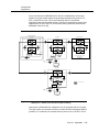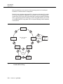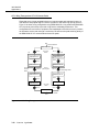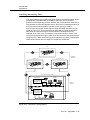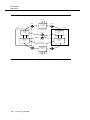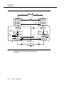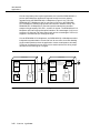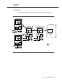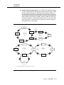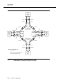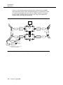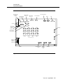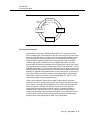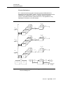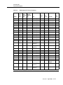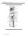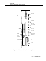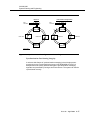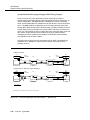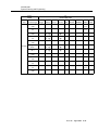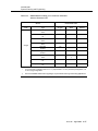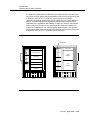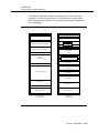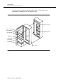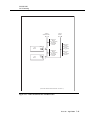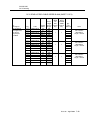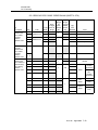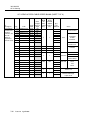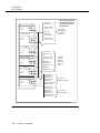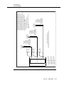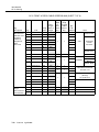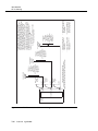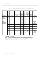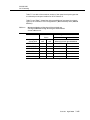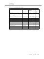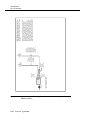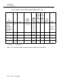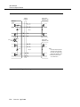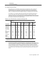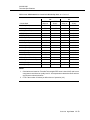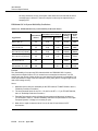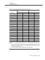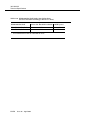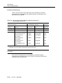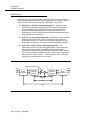
1
DDM-2000 OC-3 and OC-12 Multiplexers Applications, Planning, and Ordering Guide 363-206-200 R15 Issue 10 April 2002 Copyright© 2002 Lucent Technologies, All Rights Reserved. This material is protected by the copyright laws of the United States and other countries. It may not be reproduced, distributed or altered in any fashion by any entity, including other Lucent Technologies Business Units or Divisions, without the expressed written consent of the Lucent Learning Organization. Notice Every effort was made to ensure that the information in this document was complete and accurate at the time of printing. However, information is subject to change. Mandatory Customer Information Interference Information: Part 15 of Federal Communications Commission (FCC) Rules. NOTE: This equipment has been tested and found to comply with the limits for a Class A digital device, pursuant to Part 15 of the FCC rules. These limits are designed to provide reasonable protection against harmful interference when the equipment is operated in a commercial environment. This equipment generates, uses, and can radiate radio frequency energy and, if not installed and used in accordance with the instruction manual, may cause harmful interference to radio communications. Operation of this equipment in a residence is likely to cause harmful interference in which case the user will be required to correct the interference at his own expense. Security Statement In rare instances, unauthorized individuals make connections to the telecommunications network through the use of remote access features. In such event, applicable tariffs require that the customer pay all network charges for traffic. Lucent Technologies cannot be responsible for such charges and will not make any allowance or give any credit for charges that result from unauthorized access. Trademarks 5ESS, DACScan, LGX, SLC, ST, and Western Electric are registered trademarks of Lucent Technologies, Inc. ANSI is a registered trademark of American National Standards Institute, Inc. Common Language is a registered trademark, and CLEI, CLLI, CLCI, and CLFI are trademarks of Bell Communications Research, Inc. DEC is a trademark of Digital Equipment Corporation. Gateway 2000 is a registered trademark of Gateway 2000, Inc. Hayes is a registered trademark of Hayes Microcomputer Products, Inc. HP is a registered trademark of Hewlett-Packard Company. IBM is a registered trademark of International Business Machines Corporation. IEEE is a registered trademark of The Institute of Electrical and Electronics Engineers, Inc. MegaStar is a registered trademark of Harris Corporation. Microsoft, MS-DOS, and Windows are registered trademarks of Microsoft Corporation. National Electrical Code is a registered trademark of National Fire Protection Association, Inc. NCR is a trademark of NCR Corporation. NEC is a registered trademark of Nippon Denki Kabushiki Kaisha. NMA and TIRKS are registered trademarks of Bell Communications Research, Inc. Paradyne is a registered trademark of AT&T. Penril is a registered trademark of Penril Corporation. PROCOMM is a registered trademark of Datastorm Technologies, Inc. RIDES is a registered trademark of Ericsson Raynet. SAFARI is a registered trademark of AT&T. SPARC is a registered trademark of SPARC International, Inc. licensed exclusively to SUN Microsystems, Inc. Styrofoam is a registered trademark of The Dow Chemical Company. SUN is a registered trademark of SUN Microsystems, Inc. Titan is a registered trademark of Tellabs, Inc. V-Series is a registered trademark of General Electric Capital Corporation. Warranty Lucent Technologies provides a 1-year limited warranty on hardware and a 90-day limited warranty on software for this product. For more information, consult your local Account Executive. Document Ordering Information The ordering number for this document is 363-206-200. To order this document, call 1-888-582-3688. For more ordering information, refer to “How to Order Documents” in the section “About This Document.” Customer Assistance and Technical Support The Lucent Technologies Regional Technical Assistance Center (RTAC) provides a technical assistance telephone number which is staffed 24 hours a day. For technical assistance, simply call 1-800-225-RTAC in accordance with local operating procedures. Developed by the Lucent Learning Organization. Lucent Technologies values your comments! DDM-2000 OC-3 and OC12 Multiplexers Applications, Planning, and Ordering Guide, Release 15 (OC-3) and Release 7 (OC-12) 363-206-200 Issue 10 Date: April 2002 Lucent Technologies welcomes your comments on this information product. Your opinion is of great value and helps us to improve. 1. Was the information product: Yes No Not applicable In the language of your choice? In the desired media (paper, CD-ROM, etc.)? Available when you needed it? Please provide any additional comments: ________________________________________________________________________________________________ ________________________________________________________________________________________________ 2. Please rate the effectiveness of this information product: Excellent More than satisfactory Satisfactory Less than satisfactory Unsatisfactory Not applicable Ease of use Level of detail Readability and clarity Organization Completeness Technical accuracy Quality of translation Appearance If your response to any of the above questions is “Less than satisfactory” or “Unsatisfactory,” please explain your rating. ________________________________________________________________________________________________ ________________________________________________________________________________________________ 3. If you could change one thing about this information product, what would it be? ________________________________________________________________________________________________ ________________________________________________________________________________________________ 4. Please write any other comments about this information product: ________________________________________________________________________________________________ ________________________________________________________________________________________________ Please complete the following if we may contact you for clarification or to address your concerns: Name: ______________________________________________________ Company/organization: ______________________________ Date: ________________________________ Telephone number: ________________________________ Address: ____________________________________________________________________________________________ Email address: ______________________________ Job function: __________________________________________ If you choose to complete this form online, go to http://www.lucent-info.com/comments Otherwise fax to 407 767 2760 (U.S.) or +1 407 767 2760 (outside the U.S.) or email comments to [email protected] Table of Contents About This Document xlix ■ Purpose xlix ■ Intended Audiences xlix ■ Reason for Reissue l ■ Operations Interworking using TARP li ■ Related Documentation lii ■ How to Order Documents lxvi Standing Orders 1 lxvii ■ How to Comment on This Document lxvii ■ Electronic Documentation lxviii Introduction 1-1 ■ Overview 1-1 ■ Lucent 2000 Product Family 1-1 ■ DDM-2000 Product Family 1-2 ■ Introduction to the DDM-2000 OC-3 Multiplexer 1-4 The Year 2000 ■ 1-4 1-5 DDM-2000 OC-3 Multiplexer Releases Release Descriptions 1-5 ■ Introduction to the DDM-2000 OC-12 Multiplexer 1-19 ■ DDM-2000 OC-12 Multiplexer Releases 1-20 Release Descriptions ■ 1-20 1-27 OC-12 Regenerator Releases Release Descriptions 1-27 Issue 10 April 2002 vii Table of Contents 2 viii Features Issue 10 2-1 ■ Overview 2-1 ■ Basic Description of DDM-2000 Product Family 2-1 DDM-2000 OC-3 Multiplexer 2-1 DDM-2000 OC-12 Multiplexer 2-2 OC-12 Regenerator 2-2 DDM-2000 FiberReach Multiplexer 2-2 ■ Flexible Network Applications/Upgrades 2-2 ■ Optics 2-3 OC-1 Optics 2-3 OC-3 Optics 2-3 IS-3 Optics 2-3 OC-12 Optics 2-4 ■ Automatic Protection Switching 2-4 ■ Dual-Homed Topologies 2-4 ■ Dual Ring Interworking (DRI) Topologies 2-5 ■ Linear Optical Extensions from Rings 2-5 ■ OC-1 Extensions to DDM-2000 OC-3, OC-12, and FiberReach 2-5 ■ SONET Electrical Multiplexer 2-5 ■ Time Slot Interchange 2-6 ■ Mixed Fiber and Radio Topologies 2-6 ■ OC-3 Ring Capacity Expansion 2-6 ■ Data Service Delivery 2-7 ■ High Quality Network Synchronization and Timing 2-8 ■ Performance Monitoring for Proactive Maintenance and Tariff Verification 2-8 ■ On-Board Power Modules 2-9 ■ Low Power 2-9 ■ Flexible and Economic System Size 2-9 ■ Suitable for Any Environment 2-10 ■ Convenient Cabling Access 2-10 ■ Universal Optical Connector 2-10 April 2002 Table of Contents 3 ■ Multiple Mounting Arrangements and Enclosures 2-10 ■ SLC® Carrier Protection Switching 2-10 ■ Three-Tiered Operations 2-11 User Panel and Faceplate LEDs (Operations Tier 1) 2-11 Craft Interface Terminal (Operations Tier 2) 2-11 Operations System (OS) Interfaces (Operations Tier 3) 2-11 ■ Lucent Product Family 2000 OI 2-12 ■ Multi-Vendor OI 2-13 ■ Easy Installation 2-14 ■ Remote Software Download and Copy 2-15 ■ Software Upgrades 2-15 ■ DDM-2000 Database Backup and Restoral 2-16 ■ Remote Inventorying Capabilities 2-17 ■ Security 2-17 ■ Standards Compliance 2-18 ■ The 2000 Product Family Advantage 2-18 ■ Easy to Order 2-19 Applications 3-1 ■ Overview 3-1 ■ Introduction 3-2 ■ Network Configurations 3-3 Path Switched Rings 3-3 OC-3 Path Switched Ring 3-6 OC-12 Path Switched Rings 3-10 OC-3 Ring with OC-12 Ring Transport 3-15 OC-12 STS-1/VT1.5 Path Switched Ring (0x1) 3-19 OC-1 Path Switched Ring 3-21 OC-1 Ring Transport on OC-3 Ring 3-23 Issue 10 April 2002 ix Table of Contents Single Homing to Linear DDM-2000 OC-3 Networks 3-25 Stand-Alone OC-1 Ring/Hub Networks 3-26 OC-3 Ring Transport on OC-12 Point-to-Point 3-28 Dual Homing 3-29 OC-1 Ring Transport on OC-3 Ring x Issue 10 3-29 Dual Ring Interworking (DRI) 3-31 Dual Homing with DRI 3-37 OC-3/OC-12 Linear Optical Extensions from OC-3, OC-12, and FT-2000 Rings 3-38 Hairpin Cross-Connections on Rings 3-41 Enhanced Routing 3-42 OC-1 Ring Pass-Through 3-43 OC-1 Ring Hairpin Routing, Single-Homed 3-44 OC-1 Ring Hairpin Routing, Dual-Homed 3-45 Hairpin Local Drop Routing 3-46 Point-to-Point Topologies 3-47 OC-3 Point-to-Point 3-47 OC-12 Point-to-Point 3-53 OC-3 Repeater 3-55 OC-12 Regenerator 3-56 Hubbing 3-58 OC-3 Hubbing 3-59 OC-12 Hubbing 3-61 OC-3c Transport on OC-12 3-64 Add/Drop 3-66 Electrical Multiplexer 3-68 Lucent 2000 Product Family Interworking 3-69 SLC-2000 Access System 3-69 DACS IV-2000 Cross-Connect System 3-71 FT-2000 OC-48 Lightwave System 3-72 MegaStar 2000 Radio 3-77 Multi-Vendor OI Applications 3-78 Multi-Product OI Applications 3-79 April 2002 Table of Contents ■ 4 Service Applications 3-80 Loop Feeder 3-80 Interoffice Transport 3-80 Broadband Business Access 3-81 LAN/WAN Data Networking 3-83 Gateway Between SONET and Asynchronous Interfaces 3-87 STS-3c Video Broadcast Application 3-89 STS-3c Video Application ATM Interface 3-90 Locked STS-3c (0x1) Broadband Services 3-91 Teleprotection and SCADA Applications 3-95 Intelligent Vehicle Highway System (IVHS) Applications 3-97 DS1 Performance Monitoring for Tariff Verification 3-99 DS3 Transmultiplexer (TMUX) Application 3-101 High bit rate Digital Subscriber Line (HDSL) Application 3-102 4-1 Product Description ■ Overview 4-1 ■ Physical Design 4-2 ■ DDM-2000 OC-3 Multiplexer Shelf 4-2 DDM-2000 OC-12 Multiplexer Shelf 4-7 OC-12 Regenerator Shelf 4-13 DDM-2000 Fan Shelf 4-14 DDM-2000 OC-3 and OC-12 Multiplexer Rings Path Protection Switched Rings 4-16 Path-Protection Scheme 4-17 Dual Ring Interworking Concepts 4-19 DRI Path Protection Scheme 4-20 Hairpin Cross-Connections ■ 4-16 4-20 4-22 Transmission DDM-2000 OC-3 Multiplexer 4-22 Interfaces and Multiplexing 4-22 Issue 10 April 2002 xi Table of Contents ■ ■ Electrical Interface Circuit Packs 4-34 Optical Interface Circuit Packs 4-38 BBF5 Jumper Circuit Pack 4-52 DDM-2000 OC-12 Multiplexer 4-53 Interfaces and Multiplexing 4-53 Electrical Interface Circuit Packs 4-62 Time Slot Interchange Circuit Packs 4-62 Optical Interface Circuit Packs 4-63 Synchronization Synchronization Functions 4-66 Synchronization Circuit Packs 4-67 BBF2B/BBF2C Synchronous Timing Generator (TGS) 4-67 BBF4 Stratum 3 Timing Generator (TG3) 4-68 Control 4-69 Three-Tiered Operations Interface 4-69 4-74 Control Circuit Packs 4-74 DDM-2000 OC-3 Multiplexer 4-74 DDM-2000 OC-12 Multiplexer 4-75 Power 4-76 4-76 Group 3 and Group 4 OC-3 Shelf Differences 4-77 Group 3 vs Group 4 OC-3 Backplane Grounding 4-77 DDM-2000 OC-12 Multiplexer xii 4-69 Embedded Operations Channel DDM-2000 OC-3 Multiplexer 5 4-69 General User Panels ■ 4-66 4-78 Operations, Administration, Maintenance, and Provisioning5-1 Issue 10 ■ Overview 5-1 ■ Maintenance 5-1 April 2002 Table of Contents Single-Ended Maintenance Philosophy 5-1 Three-Tiered Operations 5-3 User Panel and Faceplate LEDs (Operations Tier 1) 5-4 Craft Interface Terminal (CIT) (Operations Tier 2) 5-8 Operations System (OS) Interface (Operations Tier 3) 5-9 Parallel Telemetry 5-9 Serial Telemetry 5-9 Miscellaneous Discretes 5-9 TL1/X.25 5-10 IAO LAN Interface 5-11 Lucent 2000 Product Family OI 5-12 Directory Services Network Element (DSNE) 5-12 Alarm Groups 5-13 Alarm Gateway Network Element (AGNE) 5-14 Multi-Vendor OI 5-14 Software Download and Copy 5-16 Maintenance Signaling 5-17 Fault Detection, Isolation, and Reporting 5-17 Loopbacks and Tests 5-18 Electrical Facility Loopbacks ■ 5-19 OC-12 Regenerator Operations and Maintenance 5-19 Order Wire 5-21 MegaStar 2000 Order Wire 5-21 5-22 Protection Switching Line Protection Switching 5-22 MegaStar 2000 Protection Switching, Linear Configuration 5-22 Path Protection Switching (Path Switched Rings) 5-24 Dual Ring Interworking (DRI) 5-24 Equipment Protection 5-25 SLC 96 Carrier Protection Switching 5-25 Issue 10 April 2002 xiii Table of Contents ■ ■ ■ ■ xiv Issue 10 Performance Monitoring 5-26 Performance Monitoring Parameters 5-26 DS1 Performance Monitoring 5-28 DS3 Performance Monitoring 5-32 Performance Monitoring Data Storage 5-34 Performance Parameter Thresholds 5-34 TCA Transmission to OS 5-34 Provisioning 5-35 General 5-35 Default Provisioning 5-35 Remote Provisioning 5-35 Cross-Connection Provisioning 5-35 Automatic Provisioning on Circuit Pack Replacement 5-36 Port State Provisioning 5-36 Channel State Provisioning 5-36 Line State Provisioning 5-37 AIS or Unequipped Provisioning 5-37 MegaStar 2000 SONET Subsystem Provisioning 5-37 Reports 5-38 Alarms and Statuses 5-38 Performance Monitoring 5-38 TCA Summary Report 5-38 Performance Status Reports 5-38 Maintenance History 5-39 States 5-39 Provisioning 5-39 Version/Equipment List 5-39 Administration 5-40 Software Upgrades 5-40 Subnetwork Size 5-41 Software Compatibility 5-42 Database Backup and Restoral 5-44 Security 5-45 April 2002 Table of Contents 6 6-1 System Planning and Engineering ■ Overview 6-1 ■ DDM-2000 OC-3/OC-12 Shelf Capacity 6-2 ■ DDM-2000 OC-3 and OC-12 Capacity and Topology Evolution 6-3 DDM-2000 OC-3 to OC-12 Capacity Upgrades 6-6 Topology Evolutions 6-8 General 6-8 OC-3 Point-to-Point Upgrade to STS-1 Drop and OC-3 Hubbing 6-8 Default Routing 6-10 OC-12 Point-to-Point Upgrade to OC-12 Hubbing 6-10 OC-3 Upgrade to DS1 Add/Drop 6-12 OC-3 Linear Network Upgrade to OC-3 Ring 6-13 OC-12 Point-to-Point Upgrade to OC-12 Ring 6-14 OC-3 Ring to OC-12 Ring Upgrade 6-15 OC-3 Ring to OC-12 Ring Capacity Upgrade 6-16 DDM-2000 OC-3/OC-12 Path Switched Ring to FT-2000 OC-48 Lightwave System Line Switched Ring 6-17 Interworking with SLC-2000 Access System 6-17 ■ Optical Link Engineering 6-17 ■ Synchronization 6-18 Network Synchronization Environment 6-18 DDM-2000 OC-3/OC-12 Synchronization Features 6-19 Timing Modes 6-19 External Timing 6-20 Line Timing 6-20 TGS Free Running 6-21 TG3 Free Running 6-21 DS1 Timing Output 6-21 DS1 Reference Cascading (MULT mode) 6-22 Subnetwork Configurations 6-22 TG3 and TGS Compatibility 6-22 Issue 10 April 2002 xv Table of Contents Free Running/Line Timing 6-22 External Timing/Loop Timing Configuration 6-25 External Timing Configuration 6-27 Network Timing Distribution 6-30 Interoffice Timing Distribution 6-30 Access Network Timing Distribution 6-32 Synchronization Messaging ■ ■ xvi Issue 10 6-33 Applications 6-34 Feature Details and Options 6-38 Examples 6-41 OC-12 Regenerator Synchronization 6-50 Network Timing Distribution Questions 6-50 Cross-Connect Provisioning 6-55 Cross-Connect Types 6-57 Allowable Cross-Connects 6-58 Physical Arrangements 6-68 Shelf Configurations 6-68 OC-3 Terminating Shelf 6-69 OC-3 Hub Shelf 6-70 OC-3 STS-1 Drop Shelf 6-71 EC-1 Electrical Multiplexer Shelf 6-72 OC-3 DS1 Add/Drop Shelf 6-73 OC-3 Ring Shelf 6-74 OC-3 Dual Ring Interworking (DRI) Shelf 6-75 OC-3 Ring Shelf with Optical Extension 6-76 OC-3 VT/STS Hairpin Shelf 6-77 OC-3 Dual Homing Shelf 6-78 OC-3 DDM-2000 FiberReach Host Shelf 6-79 OC-3 FiberReach Host Shelf - Enhanced Routing 6-81 OC-3 FiberReach Host Shelf - Enhanced Routing with 26G2-U OLIU 6-82 LAN Interface 6-83 HDSL Interface 6-85 April 2002 Table of Contents T1EXT Interface 6-86 Transmultiplexer 6-87 OC-12 Terminating Shelf (DS3/EC-1 Low-Speed Interfaces) 6-88 OC-12 Terminating Configuration (DS1/EC-1 Low-Speed Interfaces) 6-89 OC-12 Hub Shelf 6-90 OC-12 STS-1 Path Switched Ring Shelf 6-91 OC-12 STS-1/VT1.5 Path Switched Ring Configuration 6-92 6-92 OC-12 Dual Homing Shelf 6-93 OC-12 STS-3c Broadcast Shelf 6-94 OC-12 OC-3c Transport Shelf 6-95 OC-12 Regenerator Shelf 6-96 Network Bay Frames 6-97 Seismic Bay Frames 7 6-99 Cabinet Arrangements 6-99 Cabling 6-105 Environmental Specifications 6-105 7-1 OC-3 Ordering ■ Overview 7-1 ■ Record of Changes 7-1 ■ Introduction 7-2 ■ Completing an Order Blank 7-3 ■ Shelf and Cable Ordering 7-4 DDM-2000 OC-3 Shelf Assembly, ED-8C724-30, G4 Ordering7-4 DDM-2000 OC-3 ED-8C724-30, G4 Shelf Orders for Central Office Bay Arrangements 7-4 T1 Lightning and Surge Secondary Protection Assembly, ED-8C783-30 7-5 Typical Bay Arrangements for DDM-2000 OC-3 Optical Networks 7-5 Issue 10 April 2002 xvii Table of Contents ■ ■ ■ 8 xviii Typical Bay Arrangement for Combined OC-3/OC-12 Bays 7-63 Lightguide Jumper and Lightguide Slack Storage Shelf 7-64 Software Ordering DDM-2000 OC-3 Software Ording 7-117 CPRO-2000 Software Ordering 7-122 OC-3 Plug-In Ordering 7-125 Typical Equipage Applications 7-129 Plug-In Maintenance Sparing Guidelines 7-164 Universal Optical Connectors 7-169 Miscellaneous Equipment and Tools 7-177 Lightguide Jumpers 7-185 In-Line Attenuators 7-188 OC-12 Ordering Issue 10 7-117 8-1 ■ Overview 8-1 ■ Record of Changes 8-1 ■ Introduction 8-2 ■ Completing an Order Blank 8-3 ■ Shelf and Cable Ordering 8-4 DDM-2000 OC-12 Shelf Assembly, ED-8C727-30, G4 Ordering 8-4 DDM-2000 OC-12 ED-8C727-30, G4 Shelf Orders for Central Office Bay Arrangements 8-5 Typical Bay Arrangement for DDM-2000 OC-12 Optical Networks 8-5 ■ DDM-2000 OC-12 Software Ordering 8-51 ■ OC-12 Plug-Ins 8-56 Individual Plug-In Ordering 8-56 Ring Applications 8-56 Typical Equipage Applications 8-58 Plug-In Maintenance Sparing Guidelines 8-65 April 2002 Table of Contents 8-68 Universal Connector OLIUs ■ 9 Miscellaneous Equipment and Tools 8-73 Lightguide Buildout Guidelines 8-79 Lightguide Jumpers 8-80 9-1 Product Support ■ Overview 9-1 ■ Customer Technical Support (CTS) 9-1 ■ Engineering and Installation Services 9-4 Customer Technical Support Enhanced Services 10 11 9-5 ■ Documentation Support 9-5 ■ Related Training 9-6 10-1 Reliability and Quality ■ Overview 10-1 ■ Introduction 10-1 ■ Reliability Program 10-2 ■ International Standards Organization (ISO) Certification 10-2 11-1 Technical Specifications ■ Overview 11-1 ■ DDM 2000 OC-3 Multiplexer 11-1 External Transmission Interfaces 11-1 Electrical Interfaces 11-2 DS1 Low-Speed (BBF1B) 11-3 DS1PM Low-Speed (BBF3/BBF3B) 11-4 T1 Carrier Low-Speed (BBF6 T1EXT) 11-5 LAN Interface (BBF9) 11-8 Issue 10 April 2002 xix Table of Contents LAN Interface (BBF10) 11-10 HDSL Interface (BBF8) 11-13 DS3 Low-Speed (BBG4/4B) 11-14 EC-1 High-Speed and Low-Speed (BBG6) 11-16 DS3 Data Services Interface (BBG19) 11-17 Transmultiplexer (BBG20) 11-18 Lightguide Jumpers 11-20 Optical Interfaces Long Reach OC-3 Interface (21G/21G-U/ 21G2-U/21G3-U OLIU) 11-21 Intermediate Reach OC-3 Interface (22F/22F-U/ 22F2-U OLIU) 11-22 Long Reach OC-3 Interface (22G-U/22G2-U/ 22G3-U/22G4-U OLIU) 11-23 Long Reach OC-12 Interface (24G-U) 11-24 Long Reach OC-12 Interface (24H-U) 11-25 Intraoffice (IS-3) OC-3 Rate Interface (21D/21D-U and 22D-U OLIUs) 11-26 Long Reach OC-1 Interface (26G2-U/27G-U/27G2-U OLIU) 11-27 Long Reach OC-12 Interface (29G-U) 11-28 Long Reach OC-12 Interface (29H-U) 11-29 OC-3 Optical Interface Mixing 11-47 Universal Optical Connector Attenuators 11-51 SONET Overhead Bytes 11-52 Performance 11-52 Wander/Jitter 11-52 Signal Performance 11-52 Synchronization 11-53 Protection Switching 11-54 Transient Performance 11-55 Delay 11-55 Performance Monitoring 11-55 Operations Interfaces xx Issue 10 11-21 April 2002 11-59 Table of Contents Craft Interface Terminal (CIT) 11-59 Personal Computer (PC) Specifications for Software Download 11-60 Compatible Modems 11-61 CPro-2000 Graphical User Interface and Provisioning Tool 11-62 User Panel 11-63 Equipment Indicators 11-63 Office Alarms 11-63 Serial Telemetry 11-63 Parallel Telemetry 11-64 User-Definable Miscellaneous Discrete Environmental Alarms and Controls 11-64 Order Wire 11-65 TL1/X.25 Interface 11-66 Physical Specifications 11-68 Shelf Physical Characteristics 11-68 Network Bay and Cabinet Mounting 11-68 Environmental Specifications 11-69 Temperature and Humidity 11-69 EMC Requirements 11-69 Earthquake Requirements 11-70 Fire Resistance 11-70 Underwriters Laboratories 11-70 Canadian Standards Association 11-70 Power Requirements 11-71 Shelf Fuses 11-71 Power Dissipation 11-72 DDM-2000 OC-3 Reliability 11-74 Summary 11-74 Transmission Availability 11-74 Operation System Interface Availability 11-75 Optical Module Maintenance Objective 11-75 Issue 10 April 2002 xxi Table of Contents ■ Infant Mortality 11-76 DDM-2000 OC-3 System Reliability Predictions 11-77 DDM-2000 OC-12 Multiplexer 11-81 External Transmission Interfaces 11-81 Electrical Interfaces 11-81 BBG11/BBG11B Triple DS3 Low Speed (3DS3) 11-82 BBG12 Triple EC-1 Low-Speed (3STS1E) 11-84 Optical Interfaces 11-85 Lightguide Jumpers 11-85 Long Reach OC-3 Interface (21G/21G-U/21G2-U/ 21G3-U OLIU) 11-86 IS-3 Interface (21D/21D-U OLIU) 11-87 Long Reach 1310 nm OC-12 Interface (23G/23G-U OLIU) 11-92 Long Reach 1550 nm OC-12 Interface (23H/23H-U OLIU) 11-92 OC-3 Optical Interface Mixing 11-96 Universal Optical Connector Attenuators 11-96 SONET Overhead Bytes 11-96 Performance 11-96 Wander/Jitter 11-96 Signal Performance 11-96 Synchronization 11-97 Protection Switching 11-98 Transient Performance 11-98 Delay 11-99 Performance Monitoring 11-99 Operations Interfaces Craft Interface Terminal 11-102 11-102 Personal Computer Specifications for Software Download 11-103 Compatible Modems 11-104 CPro-2000 Graphical User Interface and Provisioning Tool 11-105 xxii Issue 10 User Panel 11-105 Equipment Indicators 11-105 Office Alarms 11-105 April 2002 Table of Contents Serial Telemetry 11-105 Parallel Telemetry 11-106 User-Definable Miscellaneous Discretes (Environmental Alarms and Controls) 11-106 Order Wire 11-107 TL1/X.25 Interface 11-107 Physical Specifications 11-111 OC-12 Shelf Physical Characteristics 11-111 Fan Shelf Physical Characteristics 11-111 Network Bay and Cabinet Mounting 11-111 Environmental Specifications 11-112 Temperature and Humidity 11-112 1550 nm Systems 11-112 EMC Requirements 11-112 Earthquake Requirements 11-113 Fire Resistance 11-113 Underwriters Laboratories 11-113 Canadian Standards Association 11-113 Power Requirements 11-113 Shelf Fuses 11-113 Power Dissipation 11-114 DDM-2000 OC-12 Reliability ■ 11-116 Summary 11-116 Transmission Availability 11-116 Operation System Interface Availability 11-117 Optical Module Maintenance Objective 11-117 Infant Mortality 11-117 DDM-2000 OC-12 System Reliability Predictions 11-118 11-121 OC-12 Regenerator External Transmission Interfaces 11-121 Long Reach OC-12 Interface (23R-U REGENR) 11-121 SONET Overhead Bytes 11-125 Performance 11-125 Issue 10 April 2002 xxiii Table of Contents A xxiv Wander/Jitter 11-125 Transient Performance 11-125 Performance Monitoring 11-126 User Panel 11-126 OC-12 Regenerator TL1/X.25 Interface 11-127 Physical Specifications 11-129 OC-12 Regenerator Shelf Physical Characteristics 11-129 Network Bay Mounting 11-129 OC-12 Regenerator Reliability 11-129 Summary 11-129 Circuit Pack Reliability 11-130 System Reliability Predictions 11-130 A SONET Overview Issue 10 A-1 ■ Overview A-1 ■ History A-1 ■ Basic Purpose A-2 ■ Technical Overview A-2 SONET Signal Hierarchy A-2 SONET Layers A-4 SONET Frame Structure A-6 Section Overhead A-6 Line Overhead A-7 Path Overhead A-8 STS-1 Path Overhead A-8 VT Path Overhead A-9 SONET Multiplexing Procedure A-10 SONET Demultiplexing Procedure A-12 SONET Digital Multiplexing Schemes A-15 Asynchronous Multiplexing A-15 Synchronous Multiplexing A-16 April 2002 Table of Contents ■ ■ Virtual Tributary Signals A-16 Concatenated Mode A-17 A-18 SONET Interface SONET Payloads A-19 Higher Rate Transport A-20 A-20 Conclusion Issue 10 April 2002 xxv Table of Contents xxvi Issue 10 April 2002 Figures 3 Applications 3-1 Path Switched Ring 3-5 3-2 OC-3 Path Switched Ring 3-7 3-3 DDM-2000 OC-3 Path Switched Interoffice Ring 3-8 3-4 OC-3 Path Switched Ring Using OC-3 Multiplexer and FiberReach Multiplexer With OC-3 Optics 3-9 3-5 OC-12 Path Switched Ring — STS-1 Level Path Switching 3-10 3-6 OC-12 Path Switched Ring Using OC-12 Multiplexer—Mixed STS-1 and VT1.5 Path Switching 3-11 OC-12 Path Switched Ring Using OC-12 Multiplexer and OC-3 Multiplexer With OC-12 Optics 3-12 OC-12 VT Path Switched Ring Using DDM-2000 OC-3 Multiplexer With OC-12 Optics 3-13 3-7 3-8 3-9 OC-12 Path Switched Ring Using DDM-2000 OC-12, OC-3, and FiberReach Multiplexers With OC-12 Optics 3-14 3-10 OC-3 Ring with OC-12 Ring Transport 3-15 3-11 Multinode OC-3 Ring With OC-12 Ring Transport 3-17 3-12 DDM-2000 OC-12 Path Switched Interoffice Ring 3-18 3-13 OC-12 Ring Transport (STS-1/VT1.5 0x1) With FiberReach OC-3 Rings 3-20 3-14 Folded Ring Configuration 3-22 3-15 OC-1 Ring Transport on OC-3 Ring Configuration 3-24 3-16 Single-Homed OC-1 Ring to a DDM-2000 OC-3 Linear Application 3-25 3-17 DDM-2000 FiberReach Stand-Alone OC-1 Ring 3-26 3-18 DDM-2000 FiberReach Single Homing to a Stand-Alone OC-1 Hub Host 3-27 3-19 OC-3 Ring Transport on OC-12 Point-to-Point 3-28 3-20 DDM-2000 FiberReach Dual Homing to a DDM-2000 OC-3 Ring 3-30 3-21 Dual Access Configuration 3-31 3-22 Dual Ring Interworking Concepts 3-32 Issue 10 April 2002 xxvii Figures 3-23 3-24 3-34 DDM-2000 Ring Interworking with FT-2000 OC-48 Lightwave System Transport and DACS IV-2000 Grooming 3-36 3-25 DDM-2000 FiberReach Ring Dual Homing to a DDM-2000 OC-3 Ring in a Dual Wire Center Application3-37 3-26 OC-3 Services Using Linear Optical Extensions From OC-3/OC-12 Ring 3-39 OC-3 Services Using Linear Optical Extensions From FT-2000 Ring 3-40 3-28 VT1.5 Hairpin Cross-Connections 3-41 3-29 OC-1 Ring Pass-Through in a Function Unit 3-43 3-30 Single-Homed Hairpin Routing 3-44 3-31 Dual-Homed Hairpin Routing 3-45 3-32 Hairpin Local Drop Routing 3-46 3-33 OC-3 Point-to-Point Topology 3-48 3-34 Metro Application — Copper in the Riser 3-49 3-35 Metro Application — Fiber in the Riser 3-50 3-36 Campus CENTREX Configuration 3-51 3-37 OC-3 Point-to-Point Interoffice Configuration 3-52 3-38 OC-12 Point-to-Point Loop Configuration 3-53 3-39 OC-12 Point-to-Point Interoffice Configuration 3-54 3-40 OC-3 Repeater Configuration 3-55 3-41 OC-12 Regenerator Loop Feeder Configuration (Diverse Routing) 3-56 OC-12 Regenerator Interoffice Configuration (Diverse Routing) 3-57 3-43 OC-3 Hubbing Configuration 3-59 3-44 Small Industrial Park Configuration 3-60 3-45 OC-12 Hubbing Configuration 3-61 3-46 Large Industrial Park Configuration 3-63 3-47 OC-3c Transport— Private Data/Video/ATM Network Application 3-65 DS1 Add/Drop — OC-3 Linear Configuration 3-66 3-27 3-42 3-48 xxviii OC-3/12 to FT-2000 OC-48 Lightwave System Dual Ring Interworking Issue 10 April 2002 Figures 3-49 DS1 Add/Drop — OC-3 Interoffice Configuration 3-67 3-50 DDM-2000 OC-3 Electrical Multiplexer Configuration 3-68 3-51 OC-3 Loop Carrier Interface Configuration 3-69 3-52 SLC-2000 Access System in an OC-12 Hubbing Configuration 3-70 3-53 DACS IV-2000 Access Configuration 3-71 3-54 Operations Interworking Application 3-73 3-55 OC-3 Ring Interfaces with FT-2000 OC-48 Lightwave System 3-74 DDM-2000 OC-3 to FT-2000 OC-48 Lightwave System Dual Ring Interface 3-75 OC-3 Linear Interfaces with FT-2000 OC-48 Lightwave System 3-76 OC-12 Ring Interfaces with FT-2000 OC-48 Lightwave System 3-76 MegaStar 2000 Radio Support Using DDM-2000 OC-3 Multiplexers 3-77 Interworking of OC-1/OC-3/OC-12/OC-48 with Tellabs TITAN 5500 DCS 3-78 3-61 DDM-2000 to WaveStar Connectivity 3-79 3-62 Self-Healing Medical Campus Network Application 3-82 3-63 LAN/WAN Data Networking Using DS1 Cross-Connections 3-84 LAN/ATM Data Networking Using Transmultiplexer Circuit Pack 3-85 3-65 DDM-2000 Data Service with ATM Switch 3-86 3-66 OC-12 STS-1 Drop-and-Continue to DS3 Interfaces 3-88 3-67 STS-3c Video Broadcast Application 3-90 3-68 STS-3c Video Broadcast Application for ATM Interface 3-91 3-69 Locked (0x1) STS-3c - Broadband Services Using DDM-2000 OC-12 Multiplexer 3-93 Locked (0x1) STS-3c - Broadband Services Using DDM-2000 OC-3 Multiplexer With OC-12 Optics 3-94 3-71 Teleprotection and SCADA Application 3-96 3-72 Intelligent Vehicle Highway System (IVHS) Application 3-98 3-73 DS1 Path Performance Monitoring for Tariff Verification 3-100 3-56 3-57 3-58 3-59 3-60 3-64 3-70 Issue 10 April 2002 xxix Figures 4 3-74 DS3 Transmultiplexer Application 3-101 3-75 HDSL Application 3-103 Product Description 4-1 DDM-2000 OC-3 Group 4 Shelf — Front View 4-3 4-2 DDM-2000 OC-3 Group 4 Shelf — Rear View 4-3 4-3 DDM-2000 OC-3 Multiplexer Front Panel 4-6 4-4 DDM-2000 OC-12 Group 4 Shelf — Front View 4-8 4-5 DDM-2000 OC-12 Shelf—Rear View 4-9 4-6 DDM-2000 OC-12 Front Panel 4-12 4-7 DDM-2000 OC-12 Regenerator Shelf 4-13 4-8 DDM-2000 Fan Shelf 4-14 4-9 Two-Fiber Unidirectional Ring 4-17 4-10 Ring Path Protection Switching 4-18 4-11 Dual Ring Interworking (DRI) Concepts 4-19 4-12 DRI Path Protection Switching 4-21 4-13 DDM-2000 OC-3 Multiplexer Block Diagram — Terminal 4-23 4-14 DDM-2000 OC-3 Multiplexer Block Diagram — STS-1 Drop 4-25 4-15 DDM-2000 OC-3 Multiplexer Block Diagram — Hubbing 4-26 4-16 DDM-2000 OC-3 Multiplexer Block Diagram — SONET Electrical Multiplexer 4-27 DDM-2000 OC-3 Multiplexer Block Diagram — DS1/DS3/ EC-1 Add/Drop and VT1.5/STS-1 Path Switched Ring 4-29 DDM-2000 OC-3 Multiplexer with OC-12 Optics Block Diagram 4-30 4-17 4-18 xxx Issue 10 4-19 DDM-2000 OC-3 Multiplexer Block Diagram — DDM-2000 FiberReach Host — Single Homing 4-31 4-20 DDM-2000 OC-3 Multiplexer Block Diagram - FiberReach Stand-Alone Host Configuration 4-32 4-21 DDM-2000 OC-3 Multiplexer Block Diagram — OC-3/OC-3c Repeater 4-33 4-22 Universal Optical Connector 4-41 4-23 27G2-U Dual OC-1 OLIU in OC-3 Function Unit 4-49 April 2002 Figures 4-24 DDM-2000 OC-12 Multiplexer Block Diagram — Hubbing and Terminal Node 4-54 OC-12 Multiplexer Block Diagram — VT1.5/STS-1 Path Switched Ring 4-56 4-26 Ring (0x1) Low-Speed Interfaces 4-58 4-27 OC-12 Ring Shelf with Linear (1+1) OC-3 Low-Speed Interfaces (Transmit) 4-59 OC-12 Ring Shelf with Linear (1+1) OC-3 Low-Speed Interfaces (Receive) 4-60 4-29 DDM-2000 OC-12 Regenerator Block Diagram 4-61 4-30 DDM-2000 OC-3 User Panel for Group 1 or Group 3 Shelf 4-70 4-70 4-31 DDM-2000 OC-12 User Panel for Group 1 Shelf 4-71 4-32 DDM-2000 OC-3 User Panel for Group 4 Shelves 4-72 4-33 DDM-2000 OC-12 User Panel for Group 4 Shelves 4-73 4-34 DDM-2000 OC-3 Multiplexer Power Architecture 4-76 4-35 DDM-2000 OC-12 Multiplexer Power Architecture 4-78 4-25 4-28 5 Operations, Administration, Maintenance, and Provisioning 5-1 Single-Ended Maintenance Philosophy 5-2 5-2 Three-Tiered Operations 5-3 5-3 DDM-2000 OC-3 User Panel for Group 4 Shelves 5-6 5-4 DDM-2000 OC-12 User Panel for Group 4 Shelves 5-7 5-5 OC-12 Regenerator — Operations Interfaces 5-20 5-6 MegaStar 2000 Interconnections, DDM-2000 to Radio Subsystem 5-23 DS1/DS3 Line and Path and DS3 Path Performance Monitoring 5-26 DDM-2000 DS1 Path Performance Monitoring 5-31 5-7 5-8 6 System Planning and Engineering 6-1 Point-to-Point OC-3 to OC-12 Upgrade 6-7 6-2 OC-3 Point-to-Point to OC-3 Hubbing Upgrade 6-9 Issue 10 April 2002 xxxi Figures 6-3 OC-12 Point-to-Point to OC-12 Hubbing Upgrade 6-11 6-4 OC-3 Point-to-Point to OC-3 DS1 Add/Drop Upgrade 6-12 6-5 OC-12 Point-to-Point to OC-12 Ring Upgrade 6-14 6-6 OC-3 Ring to OC-12 Ring Upgrade 6-15 6-7 OC-3 Ring to OC-12 Ring Capacity Upgrade 6-16 6-8 Free Running/Loop Timing Configuration 6-24 6-9 Multispan Free Running/Line Timing/Loop Timing Configuration 6-24 External Timing/Loop Timing Configuration — Linear Network 6-25 6-10 6-11 External Timing/Line Timing Configuration — Ring Network 6-26 6-12 External Timing Configuration — Linear Network 6-27 6-13 External Timing Configuration — Ring Network 6-28 6-14 DS1 Timing Output and Plesiochronous Timing Configurations 6-29 6-15 OC-N Derived DS1 Timing Reference 6-31 6-16 Timing from Multiplexed DS1 6-33 6-17 DS1 Timing Output — Dual Homing Linear 6-35 6-18 Synchronization Reconfiguration — Access Ring 6-37 6-19 Synchronization Reconfiguration — Externally Timed Access Ring (Sheet 1 of 2) 6-43 Synchronization Reconfiguration — Access Ring (Sheet 1 of 3) 6-45 6-21 DS1 Timing Output with Fiber Failure — (Sheet 1 of 2) 6-48 6-22 DDM-2000 OC-3 Terminating Shelf 6-69 6-23 DDM-2000 OC-3 Hub Shelf 6-70 6-24 DDM-2000 OC-3 STS-1 Drop Shelf 6-71 6-25 DDM-2000 OC-3 EC-1 Electrical Multiplexer Shelf 6-72 6-26 DDM-2000 OC-3 DS1 Add/Drop Shelf 6-73 6-27 DDM-2000 OC-3 Ring Shelf 6-74 6-28 DDM-2000 OC-3 DRI Shelf 6-75 6-29 DDM-2000 OC-3 Ring Shelf With an Optical Extension 6-76 6-30 DDM-2000 OC-3 VT/STS Hairpin Shelf 6-77 6-31 DDM-2000 OC-3 Dual Homing Shelf 6-78 6-20 xxxii Issue 10 April 2002 Figures OC-3 DDM-2000 FiberReach Host Shelf 6-33 OC-3 DDM-2000 FiberReach Host Shelf - Enhanced Routing Topologies 6-81 6-34 OC-3 DDM-2000 FiberReach Host Shelf - Enhanced Routing with 26G2-U OLIU 6-82 6-35 OC-3/OC-12 Shelf with LAN Interface 6-84 6-36 OC-3/OC-12 Shelf with HDSL Interface 6-85 6-37 OC-3/OC-12 Shelf with T1EXT Interface 6-86 6-38 OC-3/OC-12 Shelf with Transmultiplexers 6-87 6-39 DDM-2000 OC-12 Terminating Shelf (DS3/EC-1 Low-Speed Interfaces) 6-88 OC-12 Terminating Configuration (DS1/EC-1 Low-Speed Interfaces) 6-89 6-41 OC-12 Hub Shelf 6-90 6-42 OC-12 STS-1 Path Switched Ring Shelf 6-91 6-43 OC-12 STS-1/VT1.5 Path Switched Ring Configuration 6-92 6-44 DDM-2000 OC-12 Dual Homing Shelf 6-93 6-45 DDM-2000 OC-12 STS-3c Broadcast Shelf 6-94 6-46 DDM-2000 OC-12 OC-3c Transport Shelf 6-95 6-47 DDM-2000 OC-12 Regenerator Shelf 6-96 6-48 DDM-2000 OC-3 and OC-12 Multiplexer Shelf Mounting 6-97 6-49 DDM-2000 OC-3 and OC12 Bay Arrangements 6-98 6-50 80D Bulk Power Cabinet 6-100 6-51 80A Bulk Power Cabinet 6-101 6-52 80E Bulk Power Cabinet 6-102 6-53 90A BRT-2000 Cabinet 6-103 6-54 51A Cabinet 6-104 6-40 7 6-80 6-32 OC-3 Ordering 7-1-1 Typical Bay Arrangement for DDM-2000 OC-3 7-13 7-1-2 DS1 Transmission Cables — 26 Gauge 7-14 7-1-3 DS1 Transmission Cables — 22 Gauge 7-15 7-1-4 DS3/EC-1 Transmission Cable 7-16 Issue 10 April 2002 xxxiii Figures 7-1-5 DS3/EC-1 Transmission Cable 7-17 7-1-6 DS1 Timing Reference Interface and Mult Cable 7-18 7-1-7 Synchronization for Timing Distribution Cable in a Bay Arrangement 7-19 Synchronization for Timing Distribution Cable in a Single Shelf Assembly 7-20 Office Alarm Interface and Mult Cable 7-21 7-1-8 7-1-9 7-1-10 Parallel Telemetry Interface and Mult Cable 7-22 7-1-11 Modem, TBOS Interface and Bay Mult Cable for TBOS, CIT, and Modem 7-23 7-1-12 X.25 Interface, Miscellaneous Discretes, Orderwire, and LAN 7-24 7-1-13 Power for Single OC-3 Unit and Fan Assembly 7-25 7-1-14 Alarm Cable for Fan Shelf and Fan Alarm Ground Jumper Assembly 7-26 7-1-15 Power Input Cable for Bay Arrangement of OC-3 Units Without Fan Assembly 7-27 7-2-1 Typical Bay Arrangement for DDM-2000 OC-3 7-38 7-2-2 DS1 Transmission Cables — 26 Gauge 7-39 7-2-3 DS1 Transmission Cables — 22 Gauge 7-40 7-2-4 DS3/EC-1 Transmission Cable 7-41 7-2-5 DS3/EC-1 Transmission Cable 7-42 7-2-6 DS1 Timing Reference Interface and Mult Cable 7-43 7-2-7 Synchronization for Timing Distribution Cable in a Bay Arrangement 7-44 Synchronization for Timing Distribution Cable in a Single Shelf Assembly 7-45 Office Alarm Interface and Mult Cable 7-46 7-2-8 7-2-9 xxxiv 7-2-10 Parallel Telemetry Interface and Mult Cable 7-47 7-2-11 Modem, TBOS Interface and Bay Mult Cable for TBOS, CIT, and Modem 7-48 7-2-12 X.25 Interface, Miscellaneous Discretes, and Orderwire 7-49 7-2-13 Power for Single OC-3 Unit and Fan Assembly 7-50 7-2-14 Alarm Cable for Fan Shelf and Fan Alarm Ground Jumper Assembly 7-51 Issue 10 April 2002 Figures 7-2-15 Power Input Cable for Bay Arrangement of OC-3 Front Access Units Without Fan Assembly 7-3-1 7-52 Typical Bay Arrangement for DDM-2000 OC-3/OC-12 Rear Access 7-67 7-3-2 DS1 Transmission Cables — 26 Gauge 7-68 7-3-3 DS1 Transmission Cables — 22 Gauge 7-69 7-3-4 DS3/EC-1 Transmission Cable 7-70 7-3-5 DS3/EC-1 Transmission Cable 7-71 7-3-6 DS3/EC-1 Transmission Cable 7-72 7-3-7 DS3/EC-1 Transmission Cable 7-73 7-3-8 DS1 Timing Reference Interface and Mult Cable 7-74 7-3-9 Synchronization for Timing Distribution in a Bay Arrangement 7-75 7-3-10 Office Alarm Interface and Mult Cable 7-76 7-3-11 Parallel Telemetry Interface and Mult Cable 7-77 7-3-12 Modem, TBOS Interface, and Bay Mult Cable for TBOS, CIT, and Modem 7-78 7-3-13 X.25 Interface, Miscellaneous Discretes, Orderwire, and LAN 7-79 7-3-14 Alarm Cable for Fan Shelf 7-80 7-3-15 Fan Alarm Ground Assembly 7-81 7-3-16 Power Input Cable for Bay Arrangement of OC-3/OC-12 Rear Access Units 7-82 7-4-1 Typical Bay Arrangement for DDM-2000 Initial Growth Bay OC-3/OC-12 Front Access 7-93 7-4-2 DS1 Transmission Cables — 26 Gauge 7-94 7-4-3 DS1 Transmission Cables — 22 Gauge 7-95 7-4-4 DS3/EC-1 Transmission Cable 7-96 7-4-5 DS3/EC-1 Transmission Cable 7-97 7-4-6 DS3/EC-1 Transmission Cable 7-98 7-4-7 DS3/EC-1 Transmission Cable 7-99 7-4-8 DS1 Timing Reference Interface and Mult Cable 7-100 7-4-9 Synchronization for Timing Distribution Cable in a Bay Arrangement 7-101 7-4-10 Office Alarm Interface and Mult Cable 7-102 7-4-11 Parallel Telemetry Interface and Mult Cable 7-103 Issue 10 April 2002 xxxv Figures 7-4-12 Modem, TBOS Interface, and Bay Mult Cable for TBOS, CIT, and Modem 7-104 7-4-13 X.25 Interface, Miscellaneous Discretes, and Orderwire 7-105 7-4-14 Cable Assembly for Fan Alarm 7-106 7-4-15 Fan Alarm Ground Assembly 7-107 7-4-16 Power Input Cable for Bay Arrangement of OC-3/OC-12 Front Access 7-108 7-1 DDM-2000 OC-3 Shelf 7-125 7-2 End Terminal Shelf Equipped With 28 DS1, 1 DS3, and 1 EC-1 Circuits 7-130 End Terminal Shelf Equipped With 28 DS1 Performance Monitoring Circuits 7-132 Hub Shelf Equipped With 28 DS1 Circuits and 2 OC-3 Optical Extensions 7-133 7-3 7-4 7-5 Add/Drop Shelf Equipped With 28 DS1 Circuits and 1 DS3 7-134 7-6 OC-3 Repeater Shelf 7-135 7-7 Electrical SONET Shelf Equipped With 84 DS1 Circuits 7-136 7-8 Ring Shelf Equipped With 28 DS1 Circuits 7-137 7-9 Ring Shelf Equipped With 28 DS1, 1 DS3, and 1 EC-1 Circuits 7-138 OC-3 Ring Shelf Equipped With 28 DS1, 1 DS3, and 1 OC-3 Optical Extension 7-139 OC-3 Ring Shelf Equipped With 28 DS1 Circuits and 2 OC-1 Optical Extensions (DDM-2000 FiberReach Host) 7-140 MegaStar 2000 Interface Shelf Equipped With 28 DS1 Circuits, 1 DS3 7-141 OC-3 Shelf with OC-12 Ring Optics, Equipped With 28 DS1, 1 DS3, and 1 EC-1 Circuits 7-142 OC-3/12 Shelf Equipped With 84 DS1, 3 DS3, and 1 OC-3 Optical Extension 7-143 7-15 OC-3/12 Ring Shelf Equipped With 3 EC-1s and 84 DS1s 7-144 7-16 OC-3 Shelf with OC-3/OC-12 Optics, Equipped With Data SVCS/NMLI Interface 7-146 7-17 OC-3/OC-12 Shelf with HDSL Interface 7-147 7-18 OC-3/OC-12 Shelf, Equipped With Transmultiplexer 7-149 7-10 7-11 7-12 7-13 7-14 xxxvi Issue 10 April 2002 Figures 8 7-19 OC-3/OC-12 Shelf as FiberReach Host with 26G2-U OLIUs 7-150 7-20 OC-3/OC-12 Shelf, T1 Carrier Termination 7-151 7-21 OC-3/OC-12 Shelf, LAN Interface 7-153 7-22 Universal Optical Connector 7-169 OC-12 Ordering 8-1-1 Typical Bay Arrangement for DDM-2000 OC-12, Rear Access 8-9 8-1-2 DS3/EC-1 Transmission Cable 8-10 8-1-3 DS3/EC-1 Transmission Cable 8-11 8-1-4 DS1 Timing Reference Interface and Mult Cable 8-12 8-1-5 Synchronization for Timing Distribution Cable in a Bay Arrangement 8-13 Synchronization for Timing Distribution Cable in a Single Shelf Assembly 8-14 8-1-7 Office Alarm Interface and Mult Cable 8-15 8-1-8 Parallel Telemetry Interface and Mult Cable 8-16 8-1-9 Modem, TBOS Interface, and Bay Mult Cable for TBOS, CIT, and Modem 8-17 8-1-6 8-1-10 X.25 Interface, Miscellaneous Discretes, Order Wire, and LAN 8-18 8-1-11 Power for Single OC-12 Unit and Fan Assembly 8-19 8-1-12 Cable Assembly for Fan Alarm 8-20 8-1-13 Power Input Cable for Bay Arrangement of OC-12 Rear Access Units With Fan Assembly 8-21 8-2-1 Typical Bay Arrangement for DDM-2000 OC-12 Front Access 8-29 8-2-2 DS3/EC-1 Transmission Cable 8-30 8-2-3 DS3/EC-1 Transmission Cable 8-31 8-2-4 DS1 Timing Reference Interface and Mult Cable 8-32 8-2-5 Synchronization for Timing Distribution Cable in a Bay Arrangement 8-33 Synchronization for Timing Distribution Cable in a Single Shelf Assembly 8-34 8-2-6 Issue 10 April 2002 xxxvii Figures 8-2-7 Office Alarm Interface and Mult Cable 8-35 8-2-8 Parallel Telemetry Interface and Mult Cable 8-36 8-2-9 Modem, TBOS Interface, and Bay Mult Cable for TBOS, CIT, and Modem 8-37 8-2-10 X.25 Interface, Miscellaneous Discretes, and Orderwire 8-38 8-2-11 Power for Single OC-12 Unit and Fan Assembly 8-39 8-2-12 Cable Assembly for Fan Alarm 8-40 8-2-13 Power Input Cable for Bay Arrangement of OC-12 Front Access Units With Fan Assembly 8-41 8-23 DDM-2000 OC-12 Multiplexer Ring Shelf Layout 8-57 8-24 OC-12 Hub Shelf E/W 3 DS3 Circuits and 2 OC-3 Optical Extensions 8-59 8-25 OC-12 End Terminal Shelf E/W 12 EC-1 Circuits 8-60 8-26 OC-12 Ring Shelf E/W 6 DS3 Circuits and 6 EC-1 Circuits 8-61 8-61 8-27 OC-12 Regenerator Shelf Equipped to Regenerate 4 Optical Lines 8-62 Universal Optical Connector 8-70 8-28 9 Product Support 9-1 11 A xxxviii Product Support 9-3 Technical Specifications 11-1 T1EXT Span Powering 11-6 11-2 Optical System Interfaces (Points S and R) 11-30 A SONET Overview A-1 SONET STS-1 Frame — Simplified Version A-3 A-2 Section, Line, and Path Definitions A-4 A-3 SONET Frame Format A-5 A-4 VT Path Overhead Byte A-9 Issue 10 April 2002 Figures A-5 SONET Multiplexing Procedure A-11 A-6 SONET Demultiplexing Procedure A-12 A-7 STS-1 Synchronous Payload Envelope in Interior of STS-1 Frame A-14 A-8 Asynchronous Multiplexing A-15 A-9 Synchronous Multiplexing A-16 A-10 STS-3c Concatenated Payload A-17 A-11 SONET Interface A-18 Issue 10 April 2002 xxxix Figures xl Issue 10 April 2002 List of Tables 4 5 Product Description 4-1 DDM-2000 OC-3 Plug-Ins 4-4 4-2 DDM-2000 OC-12 Plug-Ins 4-10 4-3 DDM-2000 OLIU Feature Summary 4-39 Operations, Administration, Maintenance, and Provisioning 5-1 Performance Monitoring Parameters 5-29 5-2 OC-3 Multiplexer — Maximum Number of NEs in a Subnetwork 5-41 OC-12 Multiplexer — Maximum Number of NEs in a Subnetwork 5-41 OI Software Compatibility 5-42 5-3 5-4 6 System Planning and Engineering 6-1 Current DDM-2000 OC-3 Multiplexer Topology Upgrades (Note) 6-4 6-2 Current DDM-2000 OC-12 Multiplexer Topology Upgrades (Note) 6-5 6-3 Synchronization Messages using K2 Byte 6-38 6-4 Synchronization Messages using S1 Byte * 6-39 6-5 Available Synchronization References 6-41 6-6 DDM-2000 OC-3 Available VT1.5 Cross-Connections, Including Hairpin 6-56 DDM-2000 OC-3 Ring Cross-Connect Types Allowable (Main to Main) 6-58 6-7 Issue 10 April 2002 xli List of Tables 6-8 6-9 6-10 6-11 6-12 7 xlii DDM-2000 OC-3 Ring Cross-Connect Types Allowable (Main to Function Unit) 6-59 DDM-2000 OC-3 Ring Cross-Connect Types Allowable (Function Unit to Function Unit) 6-63 DDM-2000 OC-12 Linear Cross-Connects Allowable (Main to Function Unit) 6-66 DDM-2000 OC-12 Ring Cross-Connects Allowable (Main to Main) 6-66 DDM-2000 OC-12 Ring Cross-Connects Allowable (Main to Function Unit) 6-67 OC-3 Ordering Issue 10 7-1 OC-3 Shelf Order Blank 7-7 7-2 OC-3/OC-12 Bay Order Blank 7-9 7-2 OC-3 Software Ording 7-117 7-3 DDM-2000 OC-3 Discontinued Available (DA) Software 7-120 7-4 DDM-2000 OC-3 Multiplexer Application Summary Matrix 7-121 7-5 CPRO-2000 Software Ordering 7-122 7-6 Software Compatibility for DDM-2000 OC-3 7-123 7-7 Maximum Number of Low Speed Circuit Packs per Low Speed Muldem Group in Group 4 or Earlier Shelf for OC-3 Release 15. 7-155 7-8 Mixing of Low-Speed Circuit Packs in OC-3 Release 15 for Configuration #1 7-156 7-9 Mixing of Low-Speed Circuit Packs in OC-3 Release 15 for Configuration #2 7-157 7-10 DDM-2000 OC-3 Mux Circuit Pack and Software Compatibility Matrix 7-159 7-11 Sparing Guidelines 7-165 7-12 OC-3 Plug-in Worksheet (Per Shelf) 7-167 7-13 Universal Buildout Attenuators 7-171 7-14 DDM-2000 OC-3 Plug-In Order Blank 7-172 7-15 DDM-2000 OC-3 Discontinued Availability (DA) Plug-Ins 7-175 April 2002 List of Tables 8 7-16 Miscellaneous Equipment and Tools 7-178 7-17 Miscellaneous Fiber Cabling 7-179 7-18 Miscellaneous Accessories 7-180 7-19 Single-Mode Lightguide Jumpers 7-186 7-20 Multimode Lightguide Jumpers 7-187 7-21 In-Line Attenuators 7-188 OC-12 Ordering 8-1 OC-12 Shelf Order Blank 8-6 8-2 OC-12 Software Ordering 8-51 8-3 DDM-2000 OC-12 Discontinued Available (DA) Software 8-53 8-4 DDM-2000 OC-12 Multiplexer Application Summary Matrix 8-54 8-54 8-5 Software Compatibility for DDM-2000 OC-12 8-55 8-6 DDM-2000 OC-12 Multiplexer Circuit Pack and Software Compatibility Matrix 8-63 8-7 DDM-2000 OC-12 Regenerator Circuit Pack and Software Compatibility Matrix 8-65 8-8 Sparing Guidelines 8-66 8-9 OC-12 Plug-In Worksheet (Per Shelf) 8-67 8-10 Universal Buildout Attenuators 8-69 8-11 DDM-2000 OC-12 Plug-In Order Blank 8-71 8-12 DDM-2000 OC-12 Discontinued Availability (DA) Plug-Ins 8-72 8-13 Miscellaneous Equipment and Tools 8-73 8-14 Miscellaneous Fiber Cabling 8-74 8-15 Miscellaneous Accessories 8-75 8-16 Lightguide Buildout Guidelines (23G-U and 23R-U) 8-79 8-17 Lightguide Buildout Guidelines (23H-U OLIU) 8-79 8-18 Single-Mode Lightguide Jumpers 8-80 8-19 Multimode Lightguide Jumpers 8-81 Issue 10 April 2002 xliii List of Tables 9 Product Support 10 Reliability and Quality 11 Technical Specifications 11-1 Transmission Interface Standards 11-2 11-2 BBF9 and BBF10 LAN Optical and Electrical Characteristics 11-12 11-3 DS3 Interface Modes 11-15 11-4 Enhanced DS3 Performance Monitoring Modes 11-15 11-5 21G/21G-U/21G2-U/21G3-U and 21D/21D-U/22D-U OLIU Specifications 11-31 21G/21G-U/21G2-U/21G3-U and *21D/21D-U/22D-U OLIU Link Budgets 11-32 22F/22F-U/22F2-U and 22G-U/22G2-U/22G3-U/22G4-U OLIU Specifications 11-34 22F/22F-U/22F2-U, 22G-U, 22G2-U, 22G3-U, and 22G4-U OLIU Link Budgets 11-35 11-9 OC-3 OLIU Link Budget - Multimode Operation 11-37 11-10 24G-U/24H-U OLIU Specifications 11-38 11-11 24G-U/24H-U OLIU Link Budgets (Notes) 11-39 11-12 26G2-U/27G-U/27G2-U OLIU Specifications 11-41 11-13 26G2-U/27G-U/27G2-U OLIU Link Budgets (Note) 11-42 11-14 26G2-U/27G-U/27G2-U OLIU Link Budgets — Multimode Operation (Notes) 11-43 11-15 29G-U/29H-U OLIU Specifications 11-44 11-16 29G-U/29H-U OLIU Link Budgets (Notes) 11-45 11-17 OC-3 Rate OLIU Mixes - Minimum Link Budgets (dB) 11-47 11-6 11-7 11-8 xliv Issue 10 April 2002 List of Tables 11-18 OC-3 Rate OLIU Mixes - Maximum Link Budgets for SM Fiber (dB) 11-48 OC-3 Rate OLIU Mixes—Maximum Link Budgets for MM Fiber (dB) 11-50 11-20 Universal Buildout Attenuators 11-51 11-21 DDM-2000 OC-3/OC-1 Transmission Delay in Microseconds 11-55 11-19 11-22 Performance Monitoring Parameters Provisionable via the CIT 11-56 11-23 CIT Interface Pin Connections 11-59 11-24 TL1/X.25 Interface — Default VC Assignments 11-66 11-25 TL1/X.25 Interface — X.25 Packet Layer Parameters 11-67 11-26 TL1/X.25 Interface — LAPB Link Layer Parameters 11-67 11-27 TL1/X.25 Interface — EIA-232-D Pin Connections 11-68 11-28 Power Dissipation and Current Drains 11-72 11-29 DDM-2000 OC-3 System Reliability Prediction (Note 1) 11-77 11-30 DDM-2000 OC-3 Circuit Pack Reliability (Note 1) 11-78 11-31 DDM-2000 Fan Shelf Steady State Failure Rates (Based on Telcordia Technologies RPP, Issue 6, Data) 11-80 11-32 Transmission Interface Standards 11-81 11-33 DS3 Performance Monitoring Mode 11-82 11-34 Enhanced DS3 Performance Monitoring Modes 11-83 11-35 21G/21G-U/21G2-U/21G3-U and 21D/21D-U OLIU Specifications 11-88 21G/21G-U/21G2-U/21G3-U and 21D/21D-U OLIU Link Budgets (Note 1) 11-89 11-37 OC-3 OLIUs Link Budget — Multimode Operation 11-91 11-38 23G/23G-U and 23H/23H-U OLIU Specifications 11-93 11-39 23G/23G-U and 23H/23H-U OLIU Link Budgets (Note 1) 11-94 11-40 OC-12 Multiplexer and OC-12 Regenerator Transmission Delay in Microseconds 11-99 11-36 11-41 Performance Monitoring Parameters Provisionable via the CIT 11-100 11-42 CIT Interface Pin Connection 11-102 11-43 TL1/X.25 Interface — VC Assignments 11-108 Issue 10 April 2002 xlv List of Tables 11-44 TL1/X.25 Interface — X.25 Packet Layer Parameters 11-109 11-45 TL1/X.25 Interface — LAPB Link Layer Parameters 11-109 11-46 TL1/X.25 Interface - EIA-232-D Pin Connections 11-110 11-110 11-47 Power Dissipation and Current Drains 11-114 11-114 11-48 DDM-2000 OC-12 System Reliability Prediction (Note 1) 11-118 11-118 11-49 DDM-2000 OC-12 Circuit Pack Reliability (Note 1) 11-119 11-119 11-50 DDM-2000 Fan Shelf Steady State Failure Rates (Based on Telcordia Technologies RPP Issue 6 Data) 11-120 11-51 Transmission Interface Standards 11-121 11-52 23R-U REGENR Circuit Pack Specifications 11-122 11-53 OC-12 Regenerator Link Budgets (Note 1) 11-123 11-54 OC-12 Regenerator Performance Monitoring Parameters Provisionable Via the CIT 11-126 OC-12 Regenerator TL1/X.25 Interface — VC Assignments 11-127 OC-12 Regenerator TL1/X.25 Interface — X.25 Packet Layer Parameters 11-127 OC-12 Regenerator TL1/X.25 Interface - EIA-232-D Pin Connections 11-128 OC-12 Regenerator TL1/X.25 Interface — LAPB Link Layer Parameters 11-128 11-59 OC-12 Regenerator Circuit Pack Failure Rates (Note 1) 11-130 11-60 OC-12 Regenerator System Reliability Predictions 11-130 11-55 11-56 11-58 11-57 A xlvi A SONET Overview Issue 10 A-1 SONET Payloads A-19 A-2 SONET Transport Rates A-20 April 2002 About This Document Purpose This applications, planning, and ordering guide provides specific information about the features, applications, operation, engineering, and ordering of the DDM-2000 OC-3 and OC-12 Multiplexers. The following sections cover feature highlights and network applications, plus product information on transmission and control. The system-level operations philosophy and features are described in the section on operations, administration, maintenance, and provisioning (OAM&P). Other sections provide guidelines for system planning and ordering, and summarize Lucent Technologies' extensive product support program. Intended Audiences This applications, planning, and ordering guide is primarily for network planners, engineers, and sales teams. It may be used by anyone desiring specific information about the features, applications, operation, engineering, and ordering of the DDM-2000 OC-3 and OC-12 Multiplexers. Issue 10 April 2002 xlix 363-206-200 About This Document Reason for Reissue This document, Issue 10, replaces the DDM-2000 Multiplexer Applications, Planning, and Ordering Guide, Issue 9. Major changes include: ■ Removal of the 29G2-U OLIU ■ Include references to WaveStar TDM 2.5G and 10G ■ Update cable drawings and software tables ■ Update circuit pack information including availability NOTE: This APOG covers software releases up to and including TARP releases R15.0 (OC-3) and R7.0 (OC-12). The impact of introducing TARP will affect many areas of this document. Be aware that both TARP and the Lucent Directory Services (LDS) protocol operations are discussed, and that some operations and features available in pre-TARP releases will no longer be applicable in Releases 15.0/7.0. l Issue 10 April 2002 363-206-200 About This Document Operations Interworking using TARP Release 15.0 of the DDM-2000 OC-3 Multiplexer and Release 7.0 of the DDM-2000 OC-12 Multiplexer use Telcordia Technologies’ GR-253 Target ID Address Resolution Protocol (TARP). The Operations Interworking function provided by TARP offers an alternative to the Lucent Directory Services protocol (LDS)* but will impact operations in a number of ways. The following synopsis highlights TARP and its impact on network operations: Why — Lucent Technologies offers TARP for Operations Interworking as a standard protocol recommended by Telcordia Technologies for TL1 OS applications to support interworking with other vendors’ equipment (TARP is supported by multiple vendors). When — DDM-2000 OC-3 Releases 15.0 and 13.0 and DDM-2000 OC-12 Release 7.0 use TARP for OI use (transmission through non-TARP NEs will not be affected). DDM-2000 FiberReach R4.0, FT-2000 R9.1, and SLC-2000 R4.7 are also TARP compatible. Impact — The following items list some of the areas impacted by the implementation of TARP. For more detailed information, refer to the DDM-2000 OC-3 Release 15.0 Software Release Description, 363-206-231, Issue 1, and the DDM-2000 OC-12 Release 7.0 Software Release Description, 363-206-255, Issue 1. ■ Remote alarms are not reported via the DCC using the AGNE and Alarm Group concept in TARP OC-3 Release 13.x and OC-12 Release 7.x. TL1/X.25 OS systems will also retrieve remote network alarm information. ■ Remote alarms will be reported via the DCC using the AGNE and Alarm Group concept in TARP Release 15.0. TL1/X.25 OS systems will also retrieve remote network alarm information. ■ There will no longer be a DSNE, TBOS, Site, and NE information. TARP data cache will be maintained by each individual NE for its connectivity. ■ CPro-2000 Release 11.1 and ITM SNC Release 10.0 will support DDM-2000 OC-3/OC-12 Releases 15.0/7.0. ■ Releases 15.0/7.0 still support Lucent proprietary applications such as remote Craft Interface Terminal (CIT) login, remote software download, and remote NE-to-NE automatic time/date synchronization at start-up. Subnetworks of up to 256 NEs will be supported using subnetwork partitioning into multiple Level 1 areas. * Release 11.1 and any future non-TARP releases will continue to support LDS. Issue 10 April 2002 li 363-206-200 About This Document Related Documentation The following documents provide additional information about the DDM-2000 Multiplexers: ■ Number: 190-523-101 (User Manual only) Release 3.0 Order Comcode 107265944 for User Manual & Software for Release 3.0 Title: CPro-2000 User Manual Audience: Maintenance personnel Content: Using the tool to provision and maintain ring networks ■ Number: 365-576-100 (User Manual only) Release 4.0 Number: 365-576-101 (User Manual & Software) Release 4.0 Title: CPro-2000 User Manual Audience: Maintenance personnel Content: Using the tool to provision and maintain ring networks ■ Number: 365-576-110 (User Manual only) Release 5.0 Number: 365-576-111 (User Manual & Software) Release 5.0 Title: CPro-2000 User Manual Audience: Maintenance personnel Content: Using the tool to provision and maintain ring networks ■ Number: 365-576-120 (User Manual only) Release 6.0 Number: 365-576-121 (User Manual & Software) Release 6.0 Title: CPro-2000 User Manual Audience: Maintenance personnel Content: Using the tool to provision and maintain ring networks ■ Number: 365-576-125 (User Manual only) Release 6.1 Number: 365-576-126 (User Manual & Software) Release 6.1 Title: CPro-2000 User Manual Audience: Maintenance personnel Content: Using the tool to provision and maintain ring networks ■ Number: 365-576-130 (User Manual only) Release 7.0 Number: 365-576-131 (User Manual & Software) Release 7.0 Title: CPro-2000 User Manual Audience: Maintenance personnel Content: Using the tool to provision and maintain ring networks lii Issue 10 April 2002 363-206-200 About This Document ■ Number: 365-576-140 (User Manual only) Release 8.0 Number: 365-576-141 (User Manual & Software) Release 8.0 Title: CPro-2000 User Manual Audience: Maintenance personnel Content: Using the tool to provision and maintain ring networks ■ Number: 365-576-150 (User Manual only) Release 9.0 Number: 365-576-151 (User Manual & Software) Release 9.0 Title: CPro-2000 User Manual Audience: Maintenance personnel Content: Using the tool to provision and maintain ring networks ■ Number: 365-576-160 (User Manual only) Release 10.0 Number: 365-576-161 (User Manual & Software) Release 10.0 Title: CPro-2000 User Manual Audience: Maintenance personnel Content: Using the tool to provision and maintain ring networks ■ Number: 365-576-170 (User Manual only) Release 11.1 Number: 365-576-171 (User Manual & Software) Release 11.1 Title: CPro-2000 User Manual Audience: Maintenance personnel Content: Using the tool to provision and maintain ring networks ■ Number: 363-206-201 Title: DDM-2000 OC-3 Multiplexer, System Commands Quick Reference Audience: Maintenance personnel Content: Abbreviated list of system commands and parameters for DDM-2000 OC-3 Multiplexers through Release 7.2 ■ Number: 363-206-202 Title: DDM-2000 OC-3 Multiplexer User/Service Manual, Volumes I and II Audience: Maintenance personnel Content: Detailed description, technical specifications, commands and reports (Volume I), and operations and maintenance procedures (Volume II) for DDM-2000 OC-3 Multiplexers through Release 7.2 Issue 10 April 2002 liii 363-206-200 About This Document ■ Number: 363-206-204 Title: DDM-2000 OC-3 Multiplexer Installation Manual Audience: Customers planning to install the equipment Content: Customer installation instructions ■ Number: 363-206-206 Title: DDM-2000 OC-12 Multiplexer — System Commands Quick Reference Audience: Maintenance personnel Content: Abbreviated list of system commands and parameters for DDM-2000 OC-12 Multiplexers through Release 3.1 ■ Number: 107-564-270 Title: ITM SNC Users Guide Audience: Operations Personnel Content: Integrated Transport Management Subnetwork Controller information (Release 6.0 and earlier) ■ Number: 190-223-100 Title: ITM SNC Users Guide Audience: Operations Personnel Content: Integrated Transport Management Subnetwork Controller information (Release 8.0 and later) ■ Number — 107-564-288 Title — Integrated Transport Management SubNetwork Controller (ITM SNC) System Administration Guide Audience — Administration Personnel Content — Integrated Transport Management Subnetwork Controller information ■ Number: 363-206-207 Title: DDM-2000 OC-12 Multiplexer and OC-12 Regenerator User/Service Manual Audience: Maintenance personnel Content: Detailed description, technical specifications, commands and reports, and operations and maintenance procedures for DDM-2000 OC-12 Multiplexers through Release 3.1 and OC-12 Regenerator through Release 2.0 liv Issue 10 April 2002 363-206-200 About This Document ■ Number: 363-206-208 Title: DDM-2000 OC-12 Multiplexer Installation Manual Audience: Customers planning to install the equipment Content: Customer installation instructions ■ Number: 363-206-220 Title: DDM-2000 OC-3/OC-12 Multiplexer Circuit Pack Options Job Aid Audience: Maintenance personnel Content: List of circuit pack options ■ Number: 363-206-222 Title: DDM-2000 OC-3/OC-12 Multiplexer Acceptance Task List Job Aid Audience: Maintenance personnel Content: Checklist of acceptance and turnup procedures ■ Number: 363-206-223 Title: DDM-2000 OC-12 Regenerator — System Commands Quick Reference Audience: Maintenance personnel Content: Abbreviated list of system commands and parameters ■ Number: 363-206-280 Title: DDM-2000 OC-3 Multiplexer User/Service Manual, Volumes I and II Audience: Maintenance personnel Content: Detailed description, technical specifications, commands and reports (Volume I), and operations and maintenance procedures (Volume II) for DDM-2000 OC-3 Multiplexer Releases 8.1, 9.1, 11.0, and 11.1 ■ Number: 363-206-281 Title: DDM-2000 OC-3 Multiplexers — System Commands Quick Reference Audience: Maintenance personnel Content: Abbreviated list of system commands and parameters for DDM-2000 OC-3 Multiplexer Releases 8.1, 9.1, 11.0, and 11.1 ■ Number: 363-206-285 Title: DDM-2000 OC-3 Multiplexer User/Service Manual, Volumes I and II Audience: Maintenance personnel Content: Detailed description, technical specifications, commands and reports (Volume I), and operations and maintenance procedures (Volume II) for DDM-2000 OC-3 Multiplexer Release15.0 Issue 10 April 2002 lv 363-206-200 About This Document ■ Number: 363-206-286 Title: DDM-2000 OC-3 Multiplexers — System Commands Quick Reference Audience: Maintenance personnel Content: Abbreviated list of system commands and parameters for DDM-2000 OC-3 Multiplexer Release 13.0 ■ Number: 363-206-290 Title: DDM-2000 OC-12 Multiplexer User/Service Manual, Volumes I and II Audience: Maintenance personnel Content: Detailed description, technical specifications, commands and reports (Volume I), and operations and maintenance procedures (Volume II) for DDM-2000 OC-12 Multiplexer Release 5.1 ■ Number: 363-206-291 Title: DDM-2000 OC-12 Multiplexers — System Commands Quick Reference Audience: Maintenance personnel Content: Abbreviated list of system commands and parameters for DDM-2000 OC-12 Multiplexer Release 5.1 ■ Number: 363-206-295 Title: DDM-2000 OC-12 Multiplexer User/Service Manual, Volumes I and II Audience: Maintenance personnel Content: Detailed description, technical specifications, commands and reports (Volume I), and operations and maintenance procedures (Volume II) for DDM-2000 OC-12 Multiplexer Release 7.0 ■ Number: 363-206-296 Title: DDM-2000 OC-12 Multiplexers — System Commands Quick Reference Audience: Maintenance personnel Content: Abbreviated list of system commands and parameters for DDM-2000 OC-12 Multiplexer Release 7.0 lvi Issue 10 April 2002 363-206-200 About This Document ■ Number: 363-206-300 Title: DDM-2000 FiberReach Applications, Planning, and Ordering Guide Audience: Network planners, equipment engineers, and sales teams Content: Features; applications; high-level description; operations, administration, maintenance, and provisioning (OAM&P); system planning; ordering; product support; reliability information; technical specifications; and a synchronous optical network (SONET) overview ■ Number: 363-206-301 Title: DDM-2000 FiberReach User/Service Manual Audience: Maintenance personnel Content: Detailed description, technical specifications, and O&M procedures for the DDM-2000 FiberReach Multiplexer Wideband Shelf, Release 2.1 and 2.2 ■ Number: 363-206-305 Title: DDM-2000 FiberReach User/Service Manual Audience: Maintenance personnel Content: Detailed description, technical specifications, and O&M procedures for the DDM-2000 FiberReach Multiplexer Wideband Shelf, Release 3.1 and 4.0. ■ Number: 363-206-310 Title: DDM-2000 FiberReach Installation Manual Audience: Users planning to install the equipment Content: Customer installation instructions ■ Number: 824-102-144 Title: Lucent Technologies 2000 Product Family, Operations Interworking Guide For TARP Releases Audience: Maintenance personnel Content: Operations interworking information for the Lucent Technologies Product Family 2000 systems, including DDM-2000 Multiplexers and FT-2000 OC-48 Lightwave System ■ Number: 824-102-147 Title: Lucent Technologies 2000 Product Family Operations Interworking Guide Audience: Maintenance personnel Content: Operations interworking information for the Lucent Technologies Product Family 2000 systems, including DDM-2000 Multiplexers and FT-2000 OC-48 Lightwave System Issue 10 April 2002 lvii 363-206-200 About This Document ■ Number: 824-102-148 Title: FT-2000 Operations Systems Engineering Guide Audience: Engineers Content: Operations systems engineering information for the FT-2000 OC-48 Lightwave System ■ Number: 824-102-149 Title: SLC -2000 Access System Operations Systems Engineering Guide Audience: Engineers Content: Operations systems engineering information for SLC-2000 ■ Number: 824-102-151 Title: DDM-2000 Multiplexers Operations Systems Engineering Guide Audience: Engineers Content: Operations systems engineering information for the DDM-2000 OC-3, OC-12, and FiberReach Multiplexers ■ Number: 365-372-300 Title: MetropolisDMX Access Multiplexer Applications and Planning Guide Audience: Network planners, analysts, and managers Content: Features, applications, operation, engineering, support, specifications, and ordering. ■ Number: 365-372-301 Title: MetropolisDMX Access Multiplexer User Operations Guide Audience: Technicians in the field of telecommunications and communications network providers; procedural material is written primarily for maintenance, operation, and provisioning personnel responsible for the operation and maintenance of the Metropolis DMX. Content: Detailed descriptive information to the circuit pack level; acceptance, operation, and provisioning tasks. ■ Number: 365-372-302 Title: MetropolisDMX Alarm Messages and Trouble Clearing Guide Audience: Technicians in the field of telecommunications and communications network providers; procedural material (tasks) is written primarily for maintenance, operation, and provisioning personnel responsible for the operation and maintenance of the Metropolis DMX. Content: Maintenance and trouble clearing information and tasks; a central directory of alarm messages. lviii Issue 10 April 2002 363-206-200 About This Document ■ DDM-2000 OC-3 Drawings: ED-8C724-10 ED-8C724-15 ED-8C724-16 ED-8C724-20 ED-8C724-21 ED-8C724-22 ED-8C724-30 ED-8C724-31 ED-8C724-34 ED-8C724-36 ED-8C724-37 ED-8C724-38 ED-8C724-39 ED-8C724-40 ED-8C724-41 ED-8C724-42 ED-8C724-43 ED-8C733-30 SD-7C510-01 T7C510-31 T7C510-32 801-525-168 OC-3 and OC-3/OC-12 Combined Bay Arrangements Cabling Plan (Rear Access) Cabling Plan (Front Access) Cable Assemblies Cable Assemblies Cable Assemblies DDM-2000 Shelf Assembly User Panel Assembly Releases 2 and 3 Software Ordering Release 5 Software Ordering Release 6 Software Ordering Release 7 Software Ordering Release 8 Software Ordering Release 9 Software Ordering Release 11 Software Ordering Release 13 Software Ordering Release 15 Software Ordering Fan, Filter, and Baffle Assemblies Application Schematic Interconnect Wiring (Rear Access) Interconnect Wiring (Front Access) Floor Plan Data Sheets Issue 10 April 2002 lix 363-206-200 About This Document ■ DDM-2000 OC-12 Drawings: ED-8C724-10 ED-8C727-10 ED-8C727-15 ED-8C727-16 ED-8C727-20 ED-8C727-21 ED-8C727-30 ED-8C727-31 ED-8C727-34 ED-8C727-35 ED-8C727-36 ED-8C727-37 ED-8C727-41 SD-7C513-01 T7C513-31 T7C513-32 801-525-168 OC-3 and OC-3/OC-12 Combined Bay Arrangements Typical Bay Arrangements Cabling Plan (Rear Access) Cabling Plan (Front Access) Cable Assemblies Cable Assemblies Shelf Assembly User Panel Assembly DDM-2000 OC-12 Release 2 Software Ordering DDM-2000 OC-12 Release 3 Software Ordering DDM-2000 OC-12 Release 5 Software Ordering DDM-2000 OC-12 Release 7 Software Ordering DDM-2000 OC-12 Regenerator Release 2 Software Ordering Application Schematic Interconnect Wiring Diagram (Rear Access) Interconnect Wiring (Front Access) Floor Plan Data Sheets DDM-2000 equipment is also available in traditional loop enclosure arrangements, descriptions of which may be found in the following Lucent Technologies Practices: ■ Number: 363-205-000 Title: SLC Series 5 Carrier System Ordering Guide — Loop Transmission Systems (to be replaced by 363-205-010) ■ Number: 363-205-010 Title: SLC Series 5 System Applications and Planning Guide ■ Number: 626-500-105 Title: 80-type Cabinets Ordering Information and Lettering Guide ■ Number: 626-500-115 Title: 90-type Cabinets Coding and Ordering Information lx Issue 10 April 2002 363-206-200 About This Document The following documents provide additional information about WaveStar BandWidth Manager: ■ Number — 365-370-100 Title — WaveStar BandWidth Manager Installation Manual Content — Provides a step-by-step guide to system installation and setup. It also includes information needed for preinstallation site planning and postinstallation acceptance testing. ■ Number — 365-370-101 Title — WaveStar BandWidth Manager Applications, Planning, and Ordering Guide Content — Presents a high-level overview of the system, describes its applications, gives planning requirements, engineering rules, ordering information, and technical specifications. ■ Number — 365-370-102 Title — WaveStar BandWidth Manager User/Service Manual Content — Provides a detailed description of the product step-by-step information for use in daily system operations. The manual demonstrates how to perform system provisioning, operations, and administrative tasks. It also provides procedures for routine maintenance, troubleshooting, diagnostics, and component replacement. ■ Number — 365-370-103 Title — WaveStar BandWidth Manager Provisionable Parameters Job Aid Content — Provides unit numbering diagrams, system mappings, equipment module diagrams and tables, system test procedures, and performance monitoring procedures. ■ Number — 365-370-104 Title — WaveStar BandWidth Manager Operations Systems Engineering Guide Content — Provides detailed information on TL1 commands, messages, and error codes. Issue 10 April 2002 lxi 363-206-200 About This Document The following documents provide additional information about WaveStar TDM 2.5G: ■ Number — 365-371-101 Title — WaveStar TDM 2.5G Applications, Planning, and Ordering Guide Content — Presents a high-level overview of the system, describes its applications, gives planning requirements, engineering rules, ordering information, and technical specifications. ■ Number — 365-371-102 Title — WaveStar TDM 2.5G User/Service Manual Content — Provides a detailed description of the product step-by-step information for use in daily system operations. The manual demonstrates how to perform system provisioning, operations, and administrative tasks. It also provides procedures for routine maintenance, troubleshooting, diagnostics, and component replacement. ■ Number — 365-371-103 Title — WaveStar TDM 2.5G Provisionable Parameters Job Aid Content — Provides unit numbering diagrams, system mappings, equipment module diagrams and tables, system test procedures, and performance monitoring procedures. ■ Number — 365-371-104 Title — WaveStar TDM 2.5G Cross-Connection Job Aid Content — Provides unit numbering diagrams, system mappings, equipment module diagrams and tables, system test procedures, and performance monitoring procedures. ■ Number — 365-371-106 Title — WaveStar TDM 2.5G Installation Manual Content — Provides a a step-by-step guide to system installation and setup. It also includes information needed for preinstallation site planning and postinstallation acceptance testing. ■ Number — 365-371-107 Title — WaveStar TDM 2.5G Operations Systems Engineering Guide Content — Provides detailed information on TL1 commands, messages, and error codes. lxii Issue 10 April 2002 363-206-200 About This Document The following documents provide additional information about WaveStar TDM 10G: ■ Number — 365-371-301 Title — WaveStar TDM 10G Applications, Planning, and Ordering Guide Content — Presents a high-level overview of the system, describes its applications, gives planning requirements, engineering rules, ordering information, and technical specifications. ■ Number — 365-371-302 Title — WaveStar TDM 10G User/Service Manual Content — Provides a detailed description of the product step-by-step information for use in daily system operations. The manual demonstrates how to perform system provisioning, operations, and administrative tasks. It also provides procedures for routine maintenance, troubleshooting, diagnostics, and component replacement. ■ Number — 365-371-303 Title — WaveStar TDM 10G Provisionable Parameters Job Aid Content — Provides unit numbering diagrams, system mappings, equipment module diagrams and tables, system test procedures, and performance monitoring procedures. ■ Number — 365-371-304 Title — WaveStar TDM 10G Cross-Connection Job Aid Content — Provides unit numbering diagrams, system mappings, equipment module diagrams and tables, system test procedures, and performance monitoring procedures. ■ Number — 365-371-306 Title — WaveStar TDM 10G Installation Manual Content — Provides a a step-by-step guide to system installation and setup. It also includes information needed for preinstallation site planning and postinstallation acceptance testing. ■ Number — 365-371-307 Title — WaveStar TDM 10G Operations Systems Engineering Guide Content — Provides detailed information on TL1 commands, messages, and error codes. Issue 10 April 2002 lxiii 363-206-200 About This Document The following documents provide additional information about related equipment: ■ Number: 363-206-150 Title: DDM-Plus User/Service Manual ■ Number: 363-206-151 Title: DDM-Plus Installation Manual ■ Number: 363-206-152 Title: DDM-Plus Quick Reference Guide ■ Number: 363-206-156 Title: DDM-Plus Equipment Engineering and Ordering Guide ■ Number: 363-206-157 Title: DDM-Plus Wall DT Installation Manual ■ Number: 365-303-102 Title: DSX-3 Cross-Connect Bay, Description, Operation, and Maintenance Manual ■ Number: 365-301-130 Title: System III DSX-3/4, Planning, Engineering, Installation, and Operation — System Reference Guide ■ Number: 365-331-000 Title: DACS III-2000 Release 2.0 Applications, Planning, and Ordering Guide ■ Number: 365-340-800 Title: DACS IV-2000 Release 5.0 Reference Manual ■ Number: 365-575-100 Title: FT-2000 OC-48 Lightwave System Applications, Planning, and Ordering Guide ■ Number: 636-299-120 Title: LGX Distribution System, Planning, Engineering, Installation, and Operation System Reference Guide lxiv Issue 10 April 2002 363-206-200 About This Document ■ Title: MegaStar 2000 Documents Comcode 107585648 Installation Manual Comcode 407397512 Schematic Package Comcode 107585655 Reference Manual Comcode 107585671 System Application Manual Issue 10 April 2002 lxv 363-206-200 About This Document How to Order Documents To order additional copies of this document and/or request placement on the standing order list, send or call in an order as follows: Telephone Order Customer Commercial Customers * Mail Order Lucent Technologies Customer Information Center Attention: Order Entry Section 2855 N. Franklin Road P.O. Box 19901 Indianapolis, IN 46219 (Monday through Friday) Within USA: 1-888-LUCENT8 (1-888-582-3688) 7:30 a.m. to 6:30 p.m. EST FAX: 1-800-566-9568 From Europe, The Middle East & Africa: Toll 1-317-322-6416 From Canada, the Caribbean & Latin America: Toll 1-317-322-6646 From Asia, the Pacific Region & China: Toll 1-317-322-6411 Worldwide: FAX: 1-317-322-6699 Customer Information Center Web Ordering Address http://www.lucentdocs.com/cgi-bin/CIC_store.cgi RBOC/BOC Process through your Company Documentation Coordinator * For commercial customers, a check, money order, purchase order number, or charge card number is required with all orders. Make checks payable to Lucent Technologies. Lucent entities should use Form IND 1-80.80 FA, available through the Customer Information Center. lxvi Issue 10 April 2002 363-206-200 About This Document Standing Orders One-time orders include a binder (if applicable) and the document contents for the current issue in effect at the time of order. Also, you may request placement on the standing order list for all later reissues of the document. The standing order list for each document provides automatic distribution for all reissues of the document. RBOC/BOC customers should process document orders or standing order requests through their Company Documentation Coordinator. For questions regarding standing orders or to be placed on a standing order list, call the applicable Lucent Technologies Customer Information Center number listed previously. How to Comment on This Document Customer comments on DDM-2000 documents are welcome. A comment form can be found at the beginning of this document. The comment form can be faxed to 1-407-767-2760. Comments can also be e-mailed to [email protected]. A feedback form can also be found on-line at www.lucent-info.com/comments. Issue 10 April 2002 lxvii 363-206-200 About This Document Electronic Documentation Documentation for the DDM-2000 Multiplexer is now available in electronic form, on compact disk, read-only memory (CD-ROM). CD-ROM has many advantages over traditional paper documentation, including cost savings, search and retrieve capability, and the assurance of the most current documentation. CD-ROM is available by annual subscription (on standing order). ■ To order, call your Technical Information Resource Manager, your Lucent Technologies Account Executive, or the Lucent Technologies Learning Organization at 1-888-LUCENT8 (1-888-582-3688). ■ For pricing information, contact your Lucent Technologies Account Executive or the Lucent Technologies Learning Organization at 1-888-LUCENT8 (1-888-582-3688). The CD-ROM Product Line Order Number for the All Access and Transport Products Grouping is 300-100-010. ■ lxviii Issue 10 For technical information, call Lucent Technologies Documentation Support 1-800-645-6759. April 2002 1 Introduction Table of Contents Overview 1-1 Lucent 2000 Product Family 1-1 DDM-2000 Product Family 1-2 Introduction to the DDM-2000 OC-3 Multiplexer 1-4 ■ 1-4 The Year 2000 DDM-2000 OC-3 Multiplexer Releases ■ 1-5 1-5 Release Descriptions Introduction to the DDM-2000 OC-12 Multiplexer 1-19 DDM-2000 OC-12 Multiplexer Releases 1-20 ■ 1-20 Release Descriptions OC-12 Regenerator Releases ■ 1-27 1-27 Release Descriptions Issue 10 April 2002 1-i Table of Contents 1-ii Issue 10 April 2002 Introduction 1 Overview 1 1 This section introduces the Lucent 2000 Product Family and briefly describes the DDM-2000 OC-3 Multiplexer and the DDM-2000 OC-12 Multiplexer. Lucent 2000 Product Family 1 Lucent Technologies is focused on a carefully planned and growing product family designed to provide total network solutions. The 2000 Product Family complies with the synchronous optical network (SONET) standard and builds on features and capabilities that customers have found to be useful and successful in networks such as single-ended maintenance features and product upgrade capabilities. These upgrade capabilities allow a graceful evolution from today's asynchronous networks to the world-class intelligent networks of the future. The 2000 Product Family provides the significant elements of the Lucent Technologies Service Net-2000 Architecture. Lucent's Service Net-2000 Architecture starts with the network as it exists today and provides real-world solutions to build upon your existing base. It also allows a graceful evolution from rigid wire centers to a network of flexible nodes. This network distributes intelligence to where it functions best. The Service Net-2000 Architecture offers access bandwidth, service on demand, and self-healing network applications. Access bandwidth offers increased capacity, giving end users the ability to access any desired service. This increased access bandwidth, provided over fiber, offers superior network reliability while opening up new revenue opportunities. Service on demand offers high-capacity services implemented in short intervals. This application gives local exchange carriers the opportunity to generate new revenue faster by provisioning new services at a competitive "fast start" pace. At the same time, they help maintain the existing revenue base by increasing Issue 10 April 2002 1-1 363-206-200 Introduction customer satisfaction. Service on demand also reduces start-up costs, thereby improving capital management. The self-healing network application involves careful planning and provisioning of cross-product capabilities with the 2000 Product Family. At the core of this network is DACS III-2000 and DACS IV-2000 Cross-Connect Systems, the nerve center of interoffice transmission. The intelligent DACS III-2000 and DACS IV-2000 Cross-Connect Systems, working with the DACScan-2000 Controller, can identify failed connections and reroute signals according to a preestablished recovery plan. The Lucent 2000 Product Family includes the: ■ DDM-2000 OC-3 Multiplexer ■ DDM-2000 OC-12 Multiplexer ■ DDM-2000 FiberReach Multiplexer ■ FT-2000 OC-48 Lightwave System ■ DACS III-2000 Cross-Connect System ■ DACS IV-2000 Cross-Connect System ■ DACScan-2000 Controller ■ SLC-2000 Access System ■ Business Remote Terminal-2000 (BRT-2000) ■ ITM SNC Sub-Network Controller DDM-2000 Product Family 1 The DDM-2000 Product Family includes the DDM-2000 OC-3 Multiplexer, the DDM-2000 OC-12 Multiplexer, the DDM-2000 FiberReach Multiplexer, and DDM-Plus. The DDM-2000 OC-3 and OC-12 Multiplexers are designed for loop (access), interoffice (transport), and customer location applications. They start with many of the proven features of Lucent's DDM-1000 Multiplexer and extend into the future with the flexibility of the SONET standard. The DDM-2000 OC-3 Multiplexer operates at 155 Mb/s or 622 Mb/s, and the DDM-2000 OC-12 Multiplexer operates at 622 Mb/s. Both multiplexers provide flexible and evolvable network solutions. With common operations practices and circuit pack reuse, your investment (for example, technician training, circuit pack inventory) is preserved as the network evolves to higher capacities and advanced topologies. The DDM-Plus provides a cost-effective fiber extension from the DDM-1000 or DDM-2000 OC-3 and OC-12 Multiplexers transporting one to four DS1s on a fiber pair, either in a 1x1 protected or unprotected configuration. 1-2 Issue 10 April 2002 363-206-200 Introduction The DDM-2000 FiberReach Multiplexer is the newest member of the DDM-2000 product family. The DDM-2000 FiberReach Multiplexer is a full-service access product, combining a 48-line optical network unit with a complete DS1 interface product. DDM-2000 FiberReach is a SONET product that is "hosted" by either a DDM-2000 OC-3 Multiplexer or a SLC-2000 Access System. The extension from the host node is an OC-1 signal in a ring topology. The DDM-2000 FiberReach Multiplexer operates at 51.84 Mb/s. The DDM-2000 FiberReach Multiplexer can be used in DDM-Plus applications where increased capacity and interworking features are needed. FiberReach can also be equipped with OC-3 or OC-12 optics and used as a node on a ring with other DDM-2000 OC-3 or OC-12 shelves. See 363-206-300, DDM-2000 FiberReach Applications, Planning, and Ordering Guide, for more information. The DDM-2000 OC-3 Multiplexer supports many network topologies such as point-to-point, OC-3 fiber hubbing, and linear and ring DS1/DS3/EC-1 add/drop and OC-1 rings with time slot interchange (TSI) in a single 8.5 inch high shelf. The DDM-2000 OC-3 shelf, in addition, now offers ring capacity upgrade to OC-12 for higher bandwidth applications. This is achieved by replacing the OC-3 optics with OC-12 optics in the same DDM-2000 OC-3 shelf. Each topology is supported with efficiency and a full complement of operations features. The DDM-2000 OC-12 Multiplexer supports several stand alone topologies including point-to-point, hubbing, and ring configurations. In addition, the DDM-2000 OC-12 multiplexer is an efficient OC-12 upgrade to all the OC-3 network configurations. Installed together, the DDM-2000 OC-3 and OC-12 Multiplexers provide integrated DS1 to OC-12 multiplexing. The DDM-2000 OC-12 Multiplexer also supports regenerator applications in balanced and unbalanced modes. The DDM-2000 Multiplexers are designed for easy installation and operation. Centralized operations are supported by a full set of single-ended control and maintenance features. Integrated test capabilities and default provisioning simplify installation. Most tasks can be performed using faceplate LEDs, displays and controls, while a craft interface terminal (CIT) gives access to sophisticated provisioning, maintenance and reporting features. A personal computer (PC) is needed to download software and to run CPro-2000 graphical user interface tool software. In this document, the term "DDM-2000 Multiplexer" is used to reflect the DDM-2000 OC-3, DDM-2000 OC-12, and DDM-2000 FiberReach Multiplexers. Since many features, functions, and circuit packs are common among these multiplexers, information generic to all multiplexers is presented with the DDM-2000 Multiplexer designation. Information specific to a multiplexer is described with the DDM-2000 OC-3, DDM-2000 OC-12, or DDM-2000 FiberReach designation, as appropriate. Issue 10 April 2002 1-3 363-206-200 Introduction Introduction to the DDM-2000 OC-3 Multiplexer 1 The DDM-2000 OC-3 Multiplexer is a single shelf SONET digital multiplexer. It is capable of multiplexing up to 84 DS1 signals, or 3 DS3 signals, or 3 EC-1 signals or 6 OC-1 signals, or a combination of DS1, EC-1, and DS3, and OC-1 signals, into a SONET standard 155.52 Mb/s optical carrier level 3 (OC-3) signal or a 622-Mb/s OC-12 signal. The OC-3/OC-12 line, all transmission-affecting circuit packs, and the −48 V DC power feeders may be optionally protected. The shelf can be equipped to serve many diverse network applications and supports a variety of operations interfaces for current and evolving network operations needs. The DDM-2000 OC-3 Multiplexer is designed for loop (access), interoffice (transport), and customer location applications. The DDM-2000 OC-3 Multiplexer starts with many of the proven features of Lucent's DDM-1000 multiplexer and extends into the future with the flexibility of the SONET standard. A single 8.5-inch high shelf supports a mix of digital signal 1 (DS1), digital signal 3 (DS3), optical carrier level 1 (OC-1), optical carrier level 3 (OC-3), electrical carrier signal level 1 (EC-1), OC-3c (STS-3c), and IS-3 signal interfaces satisfying a wide range of lightwave terminal and SONET electrical multiplexer applications. It supports point-to-point, hubbing, DS1/DS3/EC-1 add/drop, STS-1 drop applications, ring networks, OC-1 extensions, and upgrade to OC-12. The DDM-2000 OC-3 Multiplexer is designed for easy installation and operation. Centralized operation is supported by a full set of single-ended operations (SEO), control and maintenance features. Integrated test capabilities and default provisioning simplifies installation. Most tasks can be performed using faceplate LED displays and controls, while a CIT gives access to sophisticated maintenance, provisioning, and reporting features. A PC is needed to download software and to run CPro-2000 graphical user interface tool software. Built-in maintenance capabilities support both installation and system operation. A DDM-2000 OC-3 Multiplexer can be fully tested and installed without external test equipment. The DDM-2000 OC-3 Multiplexer has a phased release plan. This manual covers Releases 2 through 15. The manual will be updated to cover additional releases as they become available. 1 The Year 2000 DDM-2000 Multiplexers will not be affected by the arrival of the year 2000. 1-4 Issue 10 April 2002 363-206-200 Introduction DDM-2000 OC-3 Multiplexer Releases 1 Release Descriptions 1 The following paragraphs provide brief descriptions of the DDM-2000 OC-3 Multiplexer releases. Some software releases are no longer available, refer to Section 7, “Software Ordering” for availability of software releases. Release 2 and later features allow additional circuit pack configurations to activate hubbing and STS-1 linear drop applications. The TL1 message-based interface to Telcordia Technologies Network Monitoring and Analysis (NMA) operations system feature comes as part of the controller hardware and software which must always be furnished separately with Release 2 and later equipment. Release 3.2 features includes three circuit packs (and associated software): the 22F intermediate reach optical line interface unit (OLIU) which provides full DS1 and DS3 add/drop capability; the 21D OLIU which provides a short-reach multimode proprietary optical interface (IS-3) between the OC-3 and OC-12 shelves; and the BBF2B TGS circuit pack which provides DS1 timing outputs. The DS1 timing output is derived from the OC-3 signal. Release 3 includes a security feature that offers security against unauthorized access to the CIT system functions. Logins, passwords, and user categories are provided. Security can be enabled or disabled. Release 5.1 supersedes Release 5.0 (from this release on, odd feature numbers are for ring releases while even feature numbers are for linear releases) and is a two-fiber, virtual tributary (VT) path switched, ring release that requires the use of 22F OLIUs in the Main-1 and Main-2 slots of all shelves in the ring. Time slots must be reserved all the way around the ring limiting the ring capacity to 84 DS1s. The ring interfaces include DS1 low-speed, DS3 with STS-1 path protection switching and cross-connections, EC-1 low-speed with VT1.5 or STS-1 based cross-connections, or mixed DS1, DS3, and EC-1 interfaces with a total capacity not exceeding the OC-3 bandwidth. Release 5.1 features include two circuit packs (and associated software): the BBF3 DS1PM which provides DS1 performance monitoring and the BBG6 STS1E (EC-1) provisioned for low-speed operation. The DS1PM can be mixed with the DS1 circuit packs in the Low-Speed Group slots. The optional DS1PM feature allows measuring of near-end performance and the extended superframe (ESF) far-end performance report of the incoming DS1 signal. This allows the service provider to determine the end-to-end performance of the DS1 signal. SONET synchronization messaging is used to communicate the quality of network timing, internal timing status, and timing states throughout a subnetwork. Issue 10 April 2002 1-5 363-206-200 Introduction Release 6.0 supports linear applications with features that include OC-3/OC-12 interworking using the open systems interconnection (OSI) seven-layer protocol stack over the data communications channel (DCC). The OSI seven-layer protocol stack refers to the OSI reference model, a logical structure for network operations standardized by the International Standards Organization (ISO). Release 6.0 also includes an optional optical carrier level 3 concatenated (OC-3c) feature provided by the 21D or 21G OLIU. This OC-3c transport feature is used to interface with broadband terminals. Release 6.0 includes one circuit pack (and associated software): the BBG6 STS1E which provides a high-speed or low-speed EC-1 interface. The STS1E circuit packs are used in the Function Unit slots for EC-1 electrical multiplexer (high-speed) or EC-1 low-speed applications. The optional VT1.5 PM feature provides the PM of the V5 byte for errored seconds (ES), severely errored seconds (SES), and unavailable seconds (UAS). The optional DS1 PM feature allows measuring of near-end performance and the ESF far-end performance report of the incoming DS1 signal. This allows the service provider to determine the end-to-end performance of the DS1 signal. Enhanced security features include additional logins. The TL1 message based interface, introduced in Release 2.0 and enhanced in subsequent releases for centralized surveillance by NMA systems is enhanced in this release to allow Telcordia Technologies OPS/INE system to provide centralized flow-through provisioning of ports and cross-connections. Release 6.2 replaces Release 6.x and includes linear optical extensions from an OC-3 ring and an automatic synchronization reconfiguration feature. Automatic synchronization reconfiguration provides the ability to automatically select another synchronization source and to automatically reconfigure the synchronization provisioning in the event of a synchronization source failure or a synchronization change in the network, for example, a fiber cut. The feature can be enabled or disabled. Additional TL1 messages support provisioning, maintenance, testing, performance monitoring, and security functions. Release 6.2 includes SLC-2000 Release 3.1 and 3.2 interworking and channel state provisioning. Channel state provisioning is a capability provided on DDM-2000 Multiplexers that suppresses reporting of alarms and events during provisioning by supporting multiple states (automatic, in-service, and not-monitored) for VT1.5 and STS-1 channels. Release 7.0 is an enhanced ring release. Release 7.0 supports a "drop and continue" feature which is used with dual ring interworking (DRI) applications and an automatic synchronization reconfiguration feature. Release 7.0 features include two plug-ins (and associated software): the 22D-U and the 22G-U OLIUs. The 22D-U OLIU provides a short-reach IS-3 with TSI optical interface between colocated OC-3 and OC-12 and SLC-2000 ring shelves. The 22G-U OLIU has the same functionality of the 22F OLIU but with a 23 dB outside plant loss budget allowing for spans of up to 51 km. The 22D-U and 22G-U OLIUs support signal 1-6 Issue 10 April 2002 363-206-200 Introduction degrade protection switching. The "U" designation for the 22D-U and 22G-U OLIUs means the OLIUs have Universal optical connectors. These OLIUs have adapters that allow the use of SC, FC, or ST connectors on the faceplates. The 22D-U and 22G-U OLIUs can be used in all releases that currently support 22F OLIUs (Release 3.1 and later). Release 7.1 is an enhanced ring release featuring interworking with an OC-12 ring and interworking with SLC-2000 Releases 3.1 and 3.2 in a ring. Release 7.1’s features include channel state provisioning, STS-1 signal degrade protection switching, OC-12 VT1.5 path switched ring (ring 0x1 low-speed interface) optical interconnections between DDM-2000 OC-3 and OC-12 ring shelves (OC-3/IS-3), enhanced DS3 PM, and additional TL1 commands and enhancements. Channel state provisioning is a capability provided on DDM-2000 OC-3 and OC-12 Multiplexers that suppresses reporting of alarms and events during provisioning by supporting multiple states (automatic, in-service, and not-monitored) for VT1.5 and STS-1 channels. The STS-1 signal degrade feature requires the 22G-U or 22D-U OLIUs and measures the BIP-8 (B3) parity violations and causes a protection switch to the alternate path if the provisioned bit error rate (BER) threshold is crossed. The OC-12 VT1.5 path switched ring (ring 0x1 low-speed interface) OC-3/IS-3 interface offers a significant advantage over the 1+1 protected OC-3/IS-3 interface for VT1.5 path switched ring applications. Ring (0x1) low-speed interface means two service lines (no protection lines) are used between the OC-12 Multiplexer ring and the OC-3 Multiplexer ring. Switching is not done on the DDM-2000 OC-12 Multiplexer; rather VT1.5 or STS-1 level switching is done at the DDM-2000 OC-3 Multiplexer. Enhanced DS3 PM provides a collection (from the fiber or high-speed interface) of the DS3 parity-bit (P-Bit) and frame and multiframe (F&M) bit errored seconds, severely errored seconds, and unavailable seconds to the already provided coding violations and severely errored frame seconds. The feature is mainly used for DS3 tariff verification. Release 7.2 is a ring release that provides OC-3 operations interworking with the FT-2000 OC-48 Lightwave System. It also allows interworking between the old controllers (BBG5 and BBG7) and the controllers (BBG8 and BBG9). DDM-2000 FiberReach (OC-1) extensions can be added to Release 7.1 rings by upgrading the rings to Release 7.2 and adding a Release 9.0 OC-3 host node. Only OC-3 DDM-2000 FiberReach host nodes need Release 9.0 software and the controllers. ■ Applications: — OC-3 operations interworking with FT-2000 OC-48 Lightwave System. Single-ended operations and DCC connectivity supported over OC-3 interfaces. Requires FT-2000 OC-48 Lightwave System Release 6.0 software. Issue 10 April 2002 1-7 363-206-200 Introduction — OC-3/IS-3 DRI with VT1.5/STS-1 drop and continue. Single-ended operations and DCC connectivity between DDM-2000 systems or DDM-2000 and FT-2000 OC-48 Lightwave Systems in DRI applications. — Increased subnetwork size. DDM-2000/SLC-2000/FT-2000 OC-48 Lightwave System subnetworks of 24 NEs. ■ Features: — Multiple Operations System (OS) Gateway Network Element (GNE). In DDM-2000/SLC-2000 networks, more than one NE can be physically connected to X.25 allowing OSs to automatically select an alternate GNE in case of primary GNE failure. The feature also allows different GNEs to support different OSs simultaneously. — Provisionable X.25 packet size of 128 or 256 bytes. — Enhanced PM. Enhancements to DS1 and DS3 line and path PM to further support tariff verification. Enhanced DS3 PM requires the BBG4B DS3 circuit pack. — CPro-2000, ITM SNC. Release 7.2 is supported by: CPro-2000 Releases R3.0, 4.0, 5.0, 6.0, 6.1, and 6.2; ITM SNC Releases 2.2, 3.0, 4.0, 5.0, 6.0, 8.0, 9.0, and 10.0. Release 8.0 is a linear release using the BBG8 system controller and BBG9 overhead controller circuit packs. ■ Applications: — OC-3 operations interworking with FT-2000 OC-48 Lightwave System. Single-ended operations and DCC connectivity supported over OC-3 interfaces. Requires FT-2000 OC-48 Lightwave System Release 6.0 software. — OC-3/IS-3 linear extensions from OC-12 rings. 1+1 linear OC-3 and IS-3 extensions from OC-12 rings. — Increased subnetwork sizes. DDM-2000/SLC-2000 subnetworks of 32 NEs. DDM-2000/SLC-2000/FT-2000 OC-48 Lightwave System subnetworks of 24 NEs. ■ Features: — Multiple Operations System (OS) Gateway Network Element (GNE). In DDM-2000/SLC-2000 networks, more than one NE can be physically connected to X.25 allowing OSs to automatically select an alternate GNE in case of primary GNE failure. The feature also allows different GNEs to support different OSs simultaneously. — Additional X.25 switched virtual circuits. Nine virtual circuits can be provisioned in any combination of switched and permanent virtual circuits for connections to OSs. 1-8 Issue 10 April 2002 363-206-200 Introduction — Provisionable X.25 packet size of 128 or 256 bytes. — Centralized operations over X.25 link. DDM-2000 CIT commands have equivalent TL1 commands. This allows centralized operations of DDM-2000 systems via the TL1/X.25 link as an alternative to CIT commands. — Controllers. The BBG8 and BBG9 controller circuit packs provide expanded memory and processing capacity needed to support large networks. Feature enhancements available with the controllers include: ■ Remote software download. Software can be downloaded from a PC connected to a DDM-2000/SLC-2000 NE to either the local or remote DDM-2000/SLC-2000 NE. ■ Electronic provisioning. Elimination of DIP switches. Provisionable parameters are set by software, thus eliminating DIP switches. CIT baud rate is provisioned automatically via autobaud detection. ■ User-assigned RT miscellaneous discretes increased from 15 to 21. ■ Upgrades to the controllers can be done in service. — Enhanced PM. Enhancements to DS1 and DS3 line and path PM to further support tariff verification. Enhanced DS3 PM requires the BBG4B DS3 circuit pack. — Enhanced security. General and reports-only users increased from 50 to 100. Lockout of nonpriviliged users and log of all login attempts is provided. — Electrical facility loopbacks. DS3, and EC-1 equipment loopbacks of the incoming low-speed signal back towards the DSX. — STS path trace. Provided in the J1 byte of the SONET path overhead to verify STS path continuity. Allows "labeling" of STS-1s and retrieval of the path by the "label" (for example, "ABC #1"). STS path trace requires the BBG4B DS3 circuit pack. — Provisionable AIS and unequipped conditions. Line or path AIS provisionable on a path basis. Provides detection and alarming of path unequipped condition. Provides user provisionable generation of AIS or path unequipped signal on a per-shelf basis. Useful in managing cross-connection provisioning if cross-connections are inadvertently deleted. — CPro-2000, ITM SNC. Release 8.0 is supported by: CPro-2000 Releases 4.0, 5.0, 6.0, 6.1, and 6.2; ITM SNC Releases 2.2, 3.0, 4.0, 5.0, 6.0, and 8.0. Issue 10 April 2002 1-9 363-206-200 Introduction Release 8.1 provides all of the features of Release 8.0 and is a linear release supporting MegaStar 2000 SONET Radio. Release 8.1 requires the BBG8 SYSCTL system controller and BBG9 or BBG10 OHCTL overhead controller. Release 8.1 may be used for non-MegaStar 2000 applications when S1 byte synchronization messaging is desired. Release 8.1 will interwork with Releases 7.2 or 9.0. ■ Applications: — MegaStar 2000 SONET Radio. Part of Lucent Technologies and Harris-Farinon MegaStar 2000 Radio system supporting mixed fiber and radio topologies. MegaStar applications require the BBG10 OHCTL. ■ Features: — S1 Byte synchronization messaging. Uses the S1 byte of the SONET overhead to pass timing status information to different nodes in a loop-timed network. Synchronization messaging mode (S1 byte or K2 byte) is provisionable on a per OC-N basis. — CPro-2000, ITM SNC. Release 8.1 is supported by: CPro-2000 Releases 5.0, 6.0, 6.1, and 6.2; ITM SNC Releases 3.0, 4.0, 5.0, 6.0, 8.0, 9.0, and 10.0. Release 9.0 provides all of the features of Release 7.2 and is a ring release using the BBG8 SYSCTL system controller and BBG9 OHCTL overhead controller circuit packs. ■ Applications: — OC-3 DDM-2000 FiberReach host. An OC-3 shelf equipped with 27G-U dual OC-1 OLIUs that supports OC-1 ring extensions from an OC-3 ring, linear, or stand-alone network. — Automatic synchronization reconfiguration of timing from both Main and Function Unit C slots. — Increased subnetwork sizes. DDM-2000/SLC-2000 subnetworks of 32 NEs. DDM-2000/SLC-2000/FT-2000 OC-48 Lightwave System subnetworks of 24 to 32 NEs. — VT hairpin. Cross-connections are allowed between Function Unit A to Function Unit C and Function Unit B to Function Unit C. Optical extensions from Function Unit A slots are also allowed. — Dual homing. Ring (0x1) low-speed interface cross-connections between Main and Function Unit slots for dual homing applications between DDM-2000 OC-3 Multiplexers and DDM-2000 FiberReach. 1-10 Issue 10 April 2002 363-206-200 Introduction — Locked cross-connections. Ring (0x1) low-speed interface or VT locked cross-connections between low-speed and high-speed time slots, locking ring traffic onto a designated ring rotation. Used in utility market applications. ■ Features: — Additional X.25 switched virtual circuits. Nine virtual circuits can be provisioned in any combination of switched and permanent virtual circuits for connections to OSs. — Centralized operations over X.25 link. DDM-2000 CIT commands have equivalent TL1 commands. This allows centralized operations of DDM-2000 systems via the TL1/X.25 link as an alternative to CIT commands. — Controllers. The BBG8 and BBG9 controller circuit packs provide expanded memory and processing capacity needed to support large networks. Feature enhancements available with the controllers include: ■ Remote software download. Software can be downloaded from a PC connected to a DDM-2000/SLC-2000 NE to either the local or remote DDM-2000/SLC-2000 NE. ■ Electronic provisioning. Elimination of DIP switches. Provisionable parameters are set by software, thus eliminating DIP switches. CIT baud rate is provisioned automatically via autobaud detection. ■ User-assigned RT miscellaneous discretes increased from 15 to 21. ■ Upgrades to the BBG8 and BBG9 controllers can be done in service. — Enhanced PM. Enhancements to DS1 and DS3 line and path PM to further support tariff verification. Enhanced DS3 PM requires the BBG4B DS3 circuit pack. — Enhanced security. General and reports-only users increased from 50 to 100. Lockout of nonpriviliged users and log of all login attempts provided. — Electrical facility loopbacks. DS3, and EC-1 equipment loopbacks of the incoming low-speed signal back towards the DSX. — STS path trace. Provided in the J1 byte of the SONET path overhead to verify STS path continuity. Allows "labeling" of STS-1s and retrieval of the path by the "label" (for example, "ABC #1"). STS path trace requires the BBG4B DS3 circuit pack. Issue 10 April 2002 1-11 363-206-200 Introduction — Provisionable AIS and unequipped conditions. Line or path AIS provisionable on a path basis. Provides detection and alarming of path unequipped condition. Provides user provisionable generation of AIS or path unequipped signal on a per-shelf basis. Useful in managing cross-connection provisioning if cross-connections are inadvertently deleted. — OC-1 line state provisioning. A capability provided on DDM-2000 OC-3 Multiplexers that suppresses reporting of alarms and events by supporting multiple states (in-service and not monitored) for OC-1 low-speed interfaces. — CPro-2000, ITM SNC. Release 9.0 is supported by: CPro-2000 Releases 3.0, 4.0, 5.0, 6.0, 6.1, and 6.2; ITM SNC Releases 2.2, 3.0, 4.0, 5.0, 6.0, and 8.0. Release 9.1 is a ring release which provides all the features of Release 9.0 and requires the BBG8 and BBG9 or BBG10 controller hardware. In addition, Release 9.1 supports the following applications and features: ■ Applications: — MegaStar 2000 SONET Radio. Part of Lucent Technologies and Harris-Farinon MegaStar 2000 Radio system supporting mixed fiber and radio topologies. MegaStar 2000 applications require BBG10 OHCTL. — Extended FiberReach topologies. Using the 27G2-U OLIU and Release 2.0 or 2.1 of FiberReach, Release 9.1 supports: ■ ■ Hairpin single and dual 0x1 cross-connects between OC-1s within the same 27G2-U OLIU. ■ Hairpin single and dual 0x1 cross-connects between 27G2-U OLIUs in different function units. ■ Pass-through cross-connects for an OC-1 ring terminated on 27G2-U OLIUs in a function unit. ■ Mixing of all supported cross-connect types. Features: — S1-byte Synchronization Messaging. Uses the S1 byte of the SONET overhead to pass timing status information to different nodes in a loop-timed network. Synchronization messaging mode (S1 byte or K2 byte) is provisionable on a per OC-3 basis. — Enhanced DS1 PM. Provides 15-minute bins for DS1 path and line performance monitoring data. 1-12 Issue 10 April 2002 363-206-200 Introduction — 4th Level of Security. A Maintenance security level, which allows access to Reports and some maintenance activities is provided in addition to the 3 current levels of privileged, general, and reports-only. — Enhanced software download. Provides a software copy capability allowing compressed files containing the software generic to be downloaded to the DDM-2000 system while the current version is still running. When the appropriate command is initiated, the new generic is executed. — Quad-DS1 electrical loopbacks. Provides an electrical facility loopback of four DS1 interfaces from a given BBF1B or BBF3 DS1 circuit pack. — Large networks. Supports DDM-2000 and FiberReach networks of up to 50 nodes. — 27G2-U OLIU. The 27G2-U OLIU supports the cross-connects necessary to provide enhanced FiberReach topologies. — CPro-2000, ITM SNC support. Release 9.1 is supported by: CPro-2000 Releases 5.0, 6.0, 6.1, and 6.2; ITM SNC Releases 2.2, 3.0, 4.0, 5.0, 6.0, and 8.0. Release 11.0 is an enhanced ring release which provides all the features of Release 9.1. In addition, Release 11.0 supports the following applications and features: ■ Applications: — OC-12 high-speed optics from OC-3 shelf. Increases ring capacity by providing low-speed DS1 and FiberReach services directly from an OC-12 ring via the OC-3 shelf. Minimizes need for back-to-back equipment. Supports mixing of OC-3 and OC-12 shelves on the same ring. — Enhanced FiberReach topologies. Supports a hairpin local drop of traffic from an OC-1 ring terminated on 27G2-U OLIUs in a function unit to a DS1/EC-1/OC-3 interface in the other function unit group. The 27G2-U is required for these applications. Also supports mixing of local drop, pass-through, and 0x1 cross-connect types. — Multi-media Data Services: A DS3 interface provides the flexibility to offer a full range of multi-media data services via embedded and new DDM-2000 networks. This full-solution offering is made possible by interfacing DDM-2000 to any of the numerous commercially available data edge devices which provide the various data services interfaces. Issue 10 April 2002 1-13 363-206-200 Introduction — Native Mode LAN Interface. By deploying DDM-2000 with an adjunct LAN router/ATM switch, Release 11.0 provides a Native Mode LAN Interface. DDM-2000 offers up to 4 LAN ports per STS-1 of bandwidth. Point-to-point and point-to-multi-point service is provided. In a later release, this functionality will be integrated directly in the DDM-2000 shelf. ■ Features: — OC-12 OLIU (24G-U) for OC-3 shelf. The 24G-U OLIU provides OC-12 optics directly from the DDM-2000 OC-3 shelf. This allows the OC-3 shelf to support and OC-12 ring, with the low-speed inputs and capacity of the OC-3 shelf. The 24G-U OLIU provides visibility to the full STS-12 bandwidth, and allows for selection of any STS-1/DS1 traffic from any 3 STS-1 on the OC-12 ring for drop at the OC-3 shelf. Remaining traffic is passed back to the OC-12 ring. — Data Services Interface. A DS3 circuit pack and cross-connect software provide the DDM-2000 interface to an external LAN router/ATM switch for providing Native Mode LAN or general data services via the SONET network. — Enhanced software download. Provides a software copy capability allowing compressed files containing the software generic to be downloaded to the DDM-2000 system. This can be done while the current version is still running. When the appropriate command is initiated, the generic is executed. Execution of the generic can be scheduled (time and date), allowing coordination of cutover of several NEs in the subnetwork. — CPro-2000, ITM SNC support. Release 11.0 is supported by: CPro-2000 Releases 6.0, 6.1, and 6.2; ITM SNC Releases 4.0, 5.0, 6.0, 8.0, 9.0, and 10.0. Release 11.1 is an enhanced ring release which provides all the features of Release 11.0. In addition, Release 11.1 supports the following applications and features: ■ Applications: — Enhanced FiberReach topologies. Supports enhanced routing with the single OC-1 26G2-U OLIU. The 26G2-U, with built-in multiplexer capabilities, can drop DS1s without the need for the MXRVO Multiplexer or BBF5 Jumper circuit packs. The 26G2-U provides OC-1 ring pass-through, OC-1 ring hairpin single-homed and dual-homed, and OC-1 ring hairpin local drop applications. — Transmultiplexer DS3 path termination. The TMUX circuit pack (BBG20) provides path termination functions for an M13 or C-bit parity DS3 signal. It demultiplexes the DS3 into 28 DS1s, performs DS1 PM, maps each DS1 into a VT1.5, and multiplexes the 28 VT1.5s into an STS-1. 1-14 Issue 10 April 2002 363-206-200 Introduction — High bit rate Digital Subscriber Line (HDSL). The HDSL circuit pack (BBF8) provides HDSL interface capability on the DDM-2000 OC-3 shelf. It allows the transport of T1 payloads, for up to 12,000 feet, over two metallic 24 AWG twisted-pair lines.* — Interworking with Tellabs TITAN † 5500/S Release 5.0 Digital Cross-Connect System. ■ Features: — STS-1 hairpin cross-connection. — Single DS1 facility loopback. — Intermediate node STS performance monitoring. This feature collects, reports, and thresholds PM status for the SONET STS-1 Path (B3) derived parameters at intermediate Network Element interfaces. — Alarm severity escalation. Allows the user to provision (enable/disable) the alarming of service affecting/non-service affecting entities. — CPro-2000, ITM SNC support. Release 11.1 is supported by: CPro-2000 Release 6.1 and 6.2; ITM SNC Release 6.0, 8.0, 9.0, and 10.0. Release 13.0 is an enhanced ring release which provides all the transmission features of Release 11.0. In addition, Release 13.0 supports the following applications and features: ■ Applications: — Enhanced FiberReach topologies. Supports enhanced routing with the single OC-1 26G2-U OLIU. The 26G2-U, with built-in multiplexer capabilities, can drop DS1s without the need for the MXRVO Multiplexer or BBF5 Jumper circuit packs. The 26G2-U provides OC-1 ring pass-through, OC-1 ring hairpin single-homed and dual-homed, and OC-1 ring hairpin local drop applications. — Transmultiplexer DS3 path termination. The TMUX circuit pack (BBG20) provides path termination functions for an M13 or C-bit parity DS3 signal. It demultiplexes the DS3 into 28 DS1s, performs DS1 PM, maps each DS1 into a VT1.5, and multiplexes the 28 VT1.5s into an STS-1. * † The HDSL circuit pack can also be installed in DDM-2000 OC-3 shelves running linear Releases 6.2 and later, and ring Releases 7.1 and later. Refer to information included with each circuit pack for provisioning instructions. TITAN is a trademark of Tellabs, Inc. Issue 10 April 2002 1-15 363-206-200 Introduction — High bit rate Digital Subscriber Line (HDSL). The HDSL circuit pack (BBF8) provides HDSL interface capability on the DDM-2000 OC-3 shelf. It allows the transport of T1 payloads, for up to 12,000 feet, over two metallic 24 AWG twisted-pair lines.* — Interworking with Tellabs TITAN † 5500/S Release 5.0 Digital Cross-Connect System. ■ Features: — Multi-Vendor Operations Interworking (OI) compatibility. ■ DDM-2000 is compatible with any other-vendor NEs that support Target ID Address Resolution (TARP) protocol, OSI, IAO LAN, and TL1/X.25 as specified in Telcordia Technologies GR-253. ■ Compatible with Tellabs TITAN 5500/S Release 5.0 Digital Cross-Connect System, including TL1 OS access. — Lucent 2000 Product Family OI compatibility. ■ Compatible with FT-2000 R8.0 (but not with earlier releases due to multi-vendor OI support). — Large subnetworks. ■ Supports large subnetworks of up to 256 NEs by partitioning into multiple areas connected via Level 2 Intermediate Systems (IS). — IntrAOffice LAN (IAO LAN). ■ Provides an extension of the SONET DCC for operations data communications. All NE-to-NE features supported over the DCC are supported over the IAO LAN. ■ Supports ITM SNC software download to DDM-2000‡ ■ Supports ITM SNC as the TL1-GNE. — STS-1 hairpin cross-connection. — Single DS1 facility loopback using the BBF3B circuit pack. * † ‡ 1-16 The HDSL circuit pack can also be installed in DDM-2000 OC-3 shelves running linear Releases 6.2 and later, and ring Releases 7.1 and later. Refer to information included with each circuit pack for provisioning instructions. TITAN is a trademark of Tellabs, Inc. This feature will be useful when upgrading from DDM-2000 OC-3 R13.0 and OC-12 R7.0 to later releases. Issue 10 April 2002 363-206-200 Introduction — Intermediate node STS performance monitoring. This feature collects, reports, and thresholds PM status for the SONET STS-1 Path (B3) derived parameters at intermediate Network Element interfaces. — Alarm severity escalation. Allows the user to provision (enable/disable) the alarming of service affecting/non-service affecting entities. — CPro-2000, ITM SNC support. Release 13.0 is supported by: CPro-2000 Release 7.0, 8.0, 9.0, 10.0, 11.1; ITM SNC Release 5.0, 6.0, 8.0, 9.0, and 10.0. Release 15.0 is an enhanced ring release which provides all the transmission features of Release 13.0. In addition, Release 15.0 supports the following applications and features: ■ New Applications: — IMA LAN Interface. With the introduction of a new low-speed circuit pack, Release 15.0 provides a direct IMA LAN to WAN interface through the DDM-2000 OC-3. ■ The IMA LAN (BBF9 metallic or BBF10 optical) circuit pack provides an interface for one 10/100BaseT, 100BaseFX IEEE 802.3 standard compliant interface. — T1 Interface. The T1EXT (BBF6) circuit pack provides line termination for two bi-directional T1 line interfaces. Signals received from the T1 interface are mapped into SONET VT1.5 signals. The resulting signals are routed to the OLIU circuit packs. The T1EXT circuit pack is used only with the enhanced MXRVO (BBG2B) circuit pack in Group 4 shelves. Requires separate secondary lightning and surge protection in outside plant applications. — STS-3c 0x1 Configuration. This application provides the ability of transporting STS-3c services on OC-3c low speed FUNCTION UNITS optical interfaces that have been provisioned for 0x1 with 29G-U/29H-U OLIUs in MAIN and 22-Type OLIUs in FUNCTION UNITS slots. STS-3c routing is restricted to FUNCTION UNITS C. — STS-1/VT1.5 0x1 Configuration. This application provides the ability of transporting STS-1 services on OC-3 low speed FUNCTION UNITS optical interfaces that have been provisioned for 0x1 with 29/24/22-Type OLIUs in MAIN and 22-Type OLIUs in FUNCTION UNITS slots of the host OC-3 shelf. Issue 10 April 2002 1-17 363-206-200 Introduction ■ New Features: — Support the OC-12 optics through the 29G-U/29H-U OLIU circuit packs in the Main Unit slots. The related features are as follows. ■ STS-1/STS-3c/VT1.5 pass-through cross-connections on the 29G-U/29H-U OC-3 equipped shelves. ■ STS-1 and VT1-5 cross-connections between MAIN slots equipped with the 29G-U/29H-U OLIU and FUNCTION UNITS slots, providing a fully flexible assignment of VT and STS-1 timeslots out of any of the 12 STS-1s that are available on the 29-type OLIU. STS-3c cross-connections to FUNCTION UNITS C only. ■ In-service upgrades to the new 29G-U/29H-U OLIU. — Stratum 3 timing generator circuit pack (BBF4). The TG3 operates with an internal oscillator of ±4.6 ppm long-term accuracy. — Support DCC provisioning on MAIN (identical) for OC-3/OC-12 ring interface. This will allow a remote OC-3 shelf to interconnect through its MAIN ring interfaces with a 1+1 linear extension on a host OC-3, OC-12, or OC-48 shelf using ring software. — Support the provisioning of asynchronous CIT port to run TL1, as well as the provisioning of the synchronous X.25 port to be used for asynchronous TL1 interface. — Remote alarm status (using the AGNE and the Alarm Group concept). — CPro-2000, ITM SNC support. Release 15.0 is supported by: CPro-2000 Releases 10.0 and 11.1; ITM SNC Release 10.0. — Software download to upgrade BBF9 and BBF10 IMA LAN circuit pack. 1-18 Issue 10 April 2002 363-206-200 Introduction Introduction to the DDM-2000 OC-12 Multiplexer 1 The DDM-2000 OC-12 Multiplexer is a single shelf SONET digital multiplexer. A single 12-inch shelf supports a mix of DS3 and OC-3 signals and multiplexes them into a SONET standard 622 Mb/s OC-12 rate. The OC-12 and OC-3 optical lines, all transmission-affecting circuit packs, and the −48 V DC power feeders may be optionally protected. The shelf can be equipped to serve many diverse network applications and supports a variety of operations interfaces for current and evolving network operations needs. The DDM-2000 OC-12 Multiplexer is designed for loop (access), interoffice (transport), and customer location applications. The DDM-2000 OC-12 Multiplexer starts with many of the proven features of Lucent's DDM-1000 and DDM-2000 OC-3 Multiplexers and extends into the future with the flexibility of the SONET standard. The DDM-2000 OC-12 Multiplexer is designed for easy installation and operation. Installation is simplified with integrated test capabilities and default provisioning. Centralized operation is supported by a full set of single-ended control and maintenance features. Built-in maintenance capabilities support both installation and system operation. A DDM-2000 OC-12 Multiplexer can be fully tested and installed without using external test equipment. Most tasks can be performed using faceplate LED displays and controls, while a CIT gives access to sophisticated maintenance, provisioning, and reporting features. A PC is needed to download software and to run CPro-2000 graphical user interface tool software. The OC-12 Regenerator extends the span length of the DDM-2000 OC-12 Multiplexer and is supported in both unbalanced and balanced modes. Diverse routing is supported in either mode, allowing one line to travel over a longer route than the other. The OC-12 Regenerator uses the same shelf and some of the same circuit packs as the OC-12 Multiplexer. The OC-12 Regenerator has been classified discontinued availability (DA). The DDM-2000 OC-12 Multiplexer has a phased release plan. This manual covers Releases 1 through 3, 5.1, 5.2, and 7.0 of the DDM-2000 OC-12 Multiplexer and Release 2 of the OC-12 Regenerator. The manual will be updated to cover additional releases as they become available. Issue 10 April 2002 1-19 363-206-200 Introduction DDM-2000 OC-12 Multiplexer Releases 1 Release Descriptions 1 The following paragraphs provide brief descriptions of the DDM-2000 OC-12 Multiplexer releases. Some software releases are no longer available, refer to Section 8, “Software Ordering” for availability of software releases. Release 1.0 and later features include OC-12 point-to-point with DS3 low-speed interfaces, OC-12 hubbing with OC-3 extensions, and OC-3/OC-12 interworking using the 21D OLIU. The TL1/X.25 message-based interface to Telcordia Technologies NMA OS feature comes as part of the controller hardware and separately ordered software required with Release 1.1 and later equipment. Hardware features include the 21D OLIU, which provides a short-reach multimode proprietary optical interface (IS-3) between the OC-3 and OC-12 shelves and the BBF2B TGS circuit pack, which provides DS1 timing outputs. Release 1.0 includes a security feature that offers security against unauthorized access to the CIT system functions. Logins, passwords, and user categories are provided. Security can be enabled or disabled. Release 2.0’s features include OC-3/OC-12 interworking using the open systems interconnection (OSI) seven-layer protocol stack over the DCC. The OSI seven-layer protocol stack refers to the OSI reference model, a logical structure for network operations standardized by the ISO. Release 2.0 also includes optical carrier level 3 concatenated (OC-3c) transport. This OC-3c transport feature can be used to interface with broadband terminals using 21D or 21G OLIUs. SONET synchronization messaging is used to communicate the quality of network timing, internal timing status, and timing states throughout a subnetwork. The OC-12 23H/23H-U OLIU provides 1550 nm optics for long reach (100 km) central office applications. Release 2.1’s applications include DDM-2000 OC-12/DACS IV-2000 transmission interworking with an EC-1 interface, DDM-2000 OC-12/FT-2000 OC-48 Lightwave System transmission interworking with an EC-1 interface, and OC-12 linear extensions from OC-3 rings. Features include an EC-1 interface with a BBG12 3STS1E low-speed interface circuit pack, TL1 interface to Telcordia Technologies Operations Systems/Intelligent Network Elements (OPS/INE) Release 1.7, and additional TL1 messages to support provisioning, maintenance, testing, performance monitoring, and security functions. Release 2.2’s applications and features include interworking with SLC-2000 Release 3.0, channel state provisioning, and additional TL1 commands and enhancements. 1-20 Issue 10 April 2002 363-206-200 Introduction Channel state provisioning is a capability provided on DDM-2000 OC-12 Multiplexers that suppresses reporting of alarms and events by supporting multiple states (automatic, in-service, and not monitored) for STS-1 channels. Release 2.3 provides OC-3 line state provisioning in addition to the features of Release 2.2. Line state provisioning allows in-service and not-monitored states of OC-3 line level alarms on Function Unit OLIUs. The alarms can be squelched and removed from the alarm report. This feature may be used in one-way OC-3c transport on OC-12 video applications. Release 3.0 is an OC-12 STS-1 path switched ring release featuring EC-1 DRI with drop and continue and automatic synchronization reconfiguration. Applications include OC-12 path switched ring, DDM-2000 OC-12/DACS IV-2000 transmission interworking, and DRI interworking via an EC-1 interface. Features include DS3 low-speed interface on an OC-12 path switched ring, EC-1 low-speed interface with the BBG12 3STS1E circuit pack, two-fiber path switched ring, ten NE maximum network from a single maintenance point, STS-1 drop and continue, nonrevertive protection switching, automatic ring synchronization reconfiguration, OSI seven-layer protocol stack on the DCC in a ring, DS1 timing outputs for timing distribution, synchronization messaging, STS-1 signal degrade, manual STS path switching, enhanced security, remote and remote software download. The BCP3 time slot interchange (TSI FLEX) circuit pack provides flexible STS-1 bandwidth management across the entire OC-12. Release 3.1’s applications and features include interworking with SLC-2000 Releases 3.1 and 3.2 ring networks, OC-12 STS-1/VT1.5 path switched ring (ring 0x1 low-speed interface) optical interconnections between DDM-2000 OC-3 and OC-12 ring shelves (OC-3/IS-3), enhanced DS3 PM, channel state provisioning, OC-3 ring to OC-12 ring inservice upgrades, low-speed EC-1 loopbacks, and additional TL1 commands and enhancements. The OC-12 STS-1/VT1.5 path switched ring (ring 0x1 low-speed interface) OC-3/IS-3 interface offers a significant advantage over the 1+1 protected OC-3/IS-3 interface for VT1.5 path switched ring applications. Ring (0x1) low-speed interface means two service lines (no protection lines) are used between the OC-12 Multiplexer ring and the OC-3 Multiplexer ring. Ring 0x1 low-speed interfaces provide full VT protection switching via an OC-12 ring, bandwidth conservation, and VT bandwidth management on the OC-12 ring. Enhanced DS3 PM provides a collection (from the fiber or high-speed interface) of the DS3 parity-bit (P-Bit) and frame and multiframe (F&M) bit errored seconds, severely errored seconds (SES), and unavailable seconds (UAS) to the already provided coding violations and severely errored frame seconds (SESF). The feature is mainly used for DS3 tariff verification. Issue 10 April 2002 1-21 363-206-200 Introduction Channel state provisioning is a capability provided on DDM-2000 OC-12 Multiplexers that suppresses reporting of alarms and events by supporting multiple states (automatic, in-service, and not-monitored) for STS-1 channels. Electronic STS-1 loopbacks (EC-1 low-speed) are provided to loop each of the three internal STS-1 signals back toward the transmit fiber. These can be used to test a new span being added to a hub or add/drop network. Release 5.0 is a ring release using the BBG8 system controller and BCP4 overhead controller circuit packs. ■ Applications: — OC-3/IS-3 DRI with STS-1/STS-3c drop and continue. DDM-2000 and DDM-2000/FT-2000 OC-48 Lightwave System rings can be interconnected over OC-3, IS-3, OC-3c, or IS-3c interfaces with single-ended operations and DCC connectivity. Upgrades from EC-1 DRI to OC-3/IS-3 DRI. — OC-3/IS-3 linear optical extensions. 1+1 protected OC-3/IS-3 linear optical extensions from OC-12 rings. — OC-3c transport for broadband services. — OC-3 operations interworking with FT-2000 OC-48 Lightwave System. Single-ended operations and DCC connectivity supported over OC-3 interfaces. Requires FT-2000 OC-48 Lightwave System Release 6.0 software. — Dual homing. An OC-3 ring can be dual-homed to two different OC-12 shelves via ring (0x1) low-speed interface interconnections. Full DCC connectivity to the OC-3 ring. — Ring (0x1) low-speed interface to OC-3 multinode ring. OC-3 multinode ring is connected to an OC-12 ring shelf via ring (0x1) low-speed interface interconnection to a single OC-12 Function Unit. Full DCC connectivity to the OC-3 ring. — STS-3c broadcast for video applications. — Increased subnetwork sizes. DDM-2000/SLC-2000 subnetworks of 32 NEs. DDM-2000/SLC-2000/FT-2000 OC-48 Lightwave System subnetworks of 24 to 32 NEs. ■ Features: — Multiple Operations System (OS) Gateway Network Element (GNE). In DDM-2000/SLC-2000 subnetworks, more than one NE can be physically connected to X.25 allowing OSs to automatically select an alternate GNE in case of primary GNE failure. The feature also allows different GNEs to support different OSs simultaneously. 1-22 Issue 10 April 2002 363-206-200 Introduction — Additional X.25 switched virtual circuits. Nine virtual circuits can be provisioned in any combination of switched and permanent virtual circuits for connections to OSs. — Provisionable X.25 packet size of 128 or 256 bytes. — Centralized operations over X.25 link. DDM-2000 CIT commands have equivalent TL1 commands. This allows centralized operations of DDM-2000 systems via the TL1/X.25 link as an alternative to CIT commands. — Controllers. The BBG8 and BCP4 controller circuit packs provide expanded memory and processing capacity needed to support large networks. Feature enhancements include: ■ Remote software download. Software can be downloaded from a PC connected to a DDM-2000/SLC-2000 NE to either the local or remote NEs. ■ Electronic provisioning. Elimination of DIP switches. Provisionable parameters are set by software, thus eliminating DIP switches. CIT baud rate is provisioned automatically via autobaud detection. ■ User assigned RT miscellaneous discretes increased from 15 to 21. ■ Upgrades to the controllers can be done in service. — Enhanced PM. Enhancements to DS3 line and path performance monitoring to further support tariff verification. Enhanced DS3 PM requires the BBG11B 3DS3 circuit pack. — Path switching and channel state provisioning for STS-3c channels. — Line state provisioning. A capability provided on DDM-2000 OC-12 Multiplexers that suppresses reporting of alarms and events by supporting multiple states (inservice and not monitored) for OC-3 low-speed interfaces. — Enhanced security. General and reports-only users increased from 50 to 100. Lockout of nonpriviliged users and log of all login attempts is provided. — Electrical facility loopbacks. DS3 and EC-1 equipment loopbacks of the incoming low-speed signal back towards the DSX. — STS path trace. Provided in the J1 byte of the SONET path overhead to verify STS path continuity. Allows "labeling" of STS-1s and retrieval of the path by the "label" (for example, "ABC #1"). STS path trace requires the BBG11B 3DS3 circuit pack. Issue 10 April 2002 1-23 363-206-200 Introduction — Provisionable AIS and unequipped conditions. Line or path AIS provisionable on a path basis. Provides detection and alarming of path unequipped condition. Provides user provisionable generation of AIS or path unequipped signal on a per-shelf basis. Useful in managing cross-connection provisioning if cross-connections are inadvertently deleted. — CPro-2000, ITM SNC support. Release 5.0 is supported by: CPro-2000 Releases 3.0, 4.0, 5.0, 6.0, 6.1, and 6.2; ITM SNC Release 2.2, 3.0, 4.0, 5.0, 6.0, and 8.0. Release 5.1 is an enhanced ring release which supports all features of R5.0. In addition, it supports the following: ■ Applications: — Enhanced DS3 Dual Ring Interworking. ■ Features: — S1 byte Synchronization Messaging. Uses the S1 byte of the SONET overhead to pass timing status information to different nodes in a loop-timed network. Synchronization messaging mode (S1 byte or K2 byte) is provisionable on a per OC-N basis. — Enhanced software download. Provides a software copy capability allowing compressed files containing the software generic to be downloaded to the DDM-2000 system while the current version is still running. When the appropriate command is initiated, the generic is executed. — 4th level of security. A Maintenance security level, which allows access to Reports and some maintenance activities is provided in addition to the 3 current levels of privileged, general, and reports-only. — Large networks. Supports DDM-2000 and FiberReach networks of up to 50 nodes. — CPro-2000, ITM SNC support. Release 5.1 is supported by: CPro-2000 Releases 5.0, 6.0, 6.1, and 6.2; ITM SNC Releases 2.2, 3.0, 4.0, 5.0, 6.0, 8.0, 9.0, and 10.0. Release 5.2 is an enhanced ring release which supports all features of R5.1. In addition, it supports the following: — STS-3c locked 0x1 cross-connect. 1-24 Issue 10 April 2002 363-206-200 Introduction Release 7.0 is an enhanced ring release which supports all features of R5.2. In addition, it supports the following: ■ Applications: — Interworking with Tellabs TITAN * 5500/S Release 5.0 Digital Cross-Connect System. ■ Features: — Target ID Address Resolution Protocol (TARP) and Telcordia Technologies compliant 2.6 standard OSI stack for intervendor operations Interworking (OI). ■ Provides for large networks up to 256 NEs via level 1 area provisioning and level 2 routing. — Enhanced software download. Provides a software copy capability allowing compressed files containing the new software generic to be downloaded to the DDM-2000 system. This can be done while the current version is still running without affecting the operation of the system. When the appropriate command is initiated, the new generic is executed. Execution of the new generic can be scheduled (time and date), allowing coordination of cutover of several NEs in the subnetwork. — IntrAOffice LAN between DDM-2000 and ITM SNC for enhanced software download and OS access. — Stratum 3 timing generator circuit pack (BBF4). The TG3 operates with an internal oscillator of ±4.6 ppm long term accuracy. — Pointer Justification Count (PJC). This performance monitoring parameter indicates a frequency error in the network or other potential synchronization problem. It provides a threshold crossing alert (TCA) when the STS-1 pointer justification count in a performance bin exceeds a user provisioned threshold value. — STS-3c locked 0x1 cross-connect. — CPro-2000, ITM SNC support. Release 7.0 is supported by: CPro-2000 Release 7.0, 8.0, 9.0, 10.0, and 11.1; ITM SNC Release 5.0, 6.0, 8.0, 9.0, and 10.0. * TITAN is a trademark of Tellabs, Inc. Issue 10 April 2002 1-25 363-206-200 Introduction Release 7.0.4 is an enhanced ring release which supports all features of R7.0. In addition, it supports the following features: ■ Remote Alarm Status — Alarm groups and alarm gateway: This feature partitions a network into maintenance domains (alarm groups) for alarm and status information. An alarm group is a set of NEs that shares status type information. Alarm groups can be nodes in a ring or any logical grouping such as maintenance group or geographic group. ■ AGNE Communication: Every NE broadcasts its network status through the AGNE to other NEs in the same alarm group. Depending on provisioning, a member of an alarm group can: — List a report of the alarms and status conditions (remote alarm reports) of all members in an alarm group, and if the NE is at the CO, a member can activate the audible office alarms for the alarm group. — Send/receive ACO requests to and from members of the same alarm group or level 1 area. — Send/receive miscellaneous discrete alarm/status closure states to and from alarm group members at the CO. 1-26 Issue 10 April 2002 363-206-200 Introduction OC-12 Regenerator Releases 1 Release Descriptions 1 Release 2.0 features include OC-12 Regenerator applications in the balanced or unbalanced mode, telemetry byte-oriented serial (TBOS) and parallel telemetry interfaces, enhanced maintenance with B2 performance monitoring for line bipolar-8 (BIP-8) errors, and a TL1 message-based interface. The line parameters monitored include errored seconds, severely errored seconds, errored seconds (Type A and B), severely errored seconds (Type A and B), severely errored framing seconds, unavailable seconds, and framing violations. Since the OC-12 Regenerator does not access the DCC, the OC-12 Regenerator software is compatible with all DDM-2000 OC-12 software releases and can be used in all OC-12 applications. The OC-12 Regenerator uses the 23R-U/23R2-U regenerator (REGENR), BBG5 system controller (SYSCTL), and BCP1 overhead controller (OHCTL) circuit packs. The 23R-U/23R2-U REGENR circuit packs have been classified discontinued availability (DA). Issue 10 April 2002 1-27 363-206-200 Introduction 1-28 Issue 10 April 2002 2 Features Table of Contents Overview 2-1 Basic Description of DDM-2000 Product Family 2-1 ■ DDM-2000 OC-3 Multiplexer 2-1 ■ DDM-2000 OC-12 Multiplexer 2-2 ■ OC-12 Regenerator 2-2 ■ DDM-2000 FiberReach Multiplexer 2-2 Flexible Network Applications/Upgrades 2-2 Optics 2-3 ■ OC-1 Optics 2-3 ■ OC-3 Optics 2-3 ■ IS-3 Optics 2-3 ■ OC-12 Optics 2-4 Automatic Protection Switching 2-4 Dual-Homed Topologies 2-4 Dual Ring Interworking (DRI) Topologies 2-5 Linear Optical Extensions from Rings 2-5 OC-1 Extensions to DDM-2000 OC-3, OC-12, and FiberReach 2-5 SONET Electrical Multiplexer 2-5 Time Slot Interchange 2-6 Mixed Fiber and Radio Topologies 2-6 Issue 10 April 2002 2-i Table of Contents OC-3 Ring Capacity Expansion 2-6 Data Service Delivery 2-7 High Quality Network Synchronization and Timing 2-8 Performance Monitoring for Proactive Maintenance and Tariff Verification 2-8 2-ii On-Board Power Modules 2-9 Low Power 2-9 Flexible and Economic System Size 2-9 Suitable for Any Environment 2-10 Convenient Cabling Access 2-10 Universal Optical Connector 2-10 Multiple Mounting Arrangements and Enclosures 2-10 SLC® Carrier Protection Switching 2-10 Three-Tiered Operations 2-11 User Panel and Faceplate LEDs (Operations Tier 1) 2-11 Craft Interface Terminal (Operations Tier 2) 2-11 Operations System (OS) Interfaces (Operations Tier 3) 2-11 Lucent Product Family 2000 OI 2-12 Multi-Vendor OI 2-13 Easy Installation 2-14 Remote Software Download and Copy 2-15 Software Upgrades 2-15 DDM-2000 Database Backup and Restoral 2-16 Remote Inventorying Capabilities 2-17 Security 2-17 Standards Compliance 2-18 The 2000 Product Family Advantage 2-18 Easy to Order 2-19 Issue 10 April 2002 Features 2 Overview 2 2 This section lists and briefly describes the feature highlights of the DDM-2000 OC-3 and OC-12 Multiplexers. The features are described in Section 3, "Applications," Section 4, "Product Description," and Section 5, "Operations, Administration, Maintenance, and Provisioning," as applicable. Basic Description of DDM-2000 Product Family 2 DDM-2000 OC-3 Multiplexer 2 The DDM-2000 OC-3 Multiplexer is a synchronous optical network (SONET) standard compliant optical carrier, level 3 (OC-3) multiplexer. It multiplexes data coming into its low-speed ports and channels together to form one OC-12, one OC-3, or two OC-1 high-speed optical signals. In the opposite direction, it demultiplexes data from its high-speed port to its low-speed ports. The high-speed optical interface and time slot interchange (TSI) of the DDM-2000 OC-3 Multiplexer operates at 622 Mb/s, 155 Mb/s, or 51.84 Mb/s. It supports 84 DS1s, 42 T1s, 3 DS3s, 3 EC-1s, 3 OC-3s, 1 OC-3c, 6 OC-1s, 6 IMA LANs, or a mixture of these (up to a capacity equivalent to 84 DS1s) in its low-speed ports. When hosting FiberReach Multiplexers, the DDM-2000 OC-3 Multiplexer has additional flexibility in signal routing. See “Enhanced Routing” in Chapter 3 for more information. Issue 10 April 2002 2-1 363-206-200 Features DDM-2000 OC-12 Multiplexer 2 The DDM-2000 OC-12 Multiplexer is a SONET standard compliant OC-12 multiplexer. It multiplexes data coming into its low-speed ports and channels together to form the OC-12 high-speed optical signal. In the opposite direction, it demultiplexes data from its high-speed port to its low-speed ports. The high-speed optical interface and TSI of the DDM-2000 OC-12 Multiplexer operates at 622 Mb/s. It supports 12 DS3s, 12 EC-1s, 4 OC-3s, 4 OC-3cs, or a mixture of these (up to a capacity equivalent to 12 DS3s) in its low-speed ports. OC-12 Regenerator 2 The OC-12 Regenerator extends the span length of the DDM-2000 OC-12 Multiplexer, making it well suited for interoffice applications. OC-12 Regenerators are supported in both balanced (equal numbers of regenerators on service and protection lines) and unbalanced (unequal numbers of regenerators on service and protection lines) modes. Diverse routing is supported in either mode, allowing one line to travel over a longer route than the other. The OC-12 Regenerator offers streamlined operations and maintenance capabilities. These capabilities allow the regenerator to be deployed in remote sites as well as central offices. The OC-12 Regenerator has been classified discontinued availability (DA). DDM-2000 FiberReach Multiplexer 2 The DDM-2000 FiberReach Multiplexer is the newest member of the DDM-2000 product family. The DDM-2000 FiberReach Multiplexer is a full-service access product, combining a 48-line optical network unit with a complete DS1 interface product. DDM-2000 FiberReach is a SONET product that is "hosted" by either a DDM-2000 OC-3 Multiplexer or a SLC-2000 Access System. The extension from the host node is an OC-1 signal in a ring topology. See 363-206-300, DDM-2000 FiberReach Applications, Planning, and Ordering Guide, for more information. Flexible Network Applications/Upgrades 2 The DDM-2000 Multiplexers form an efficient and highly flexible system, satisfying a wide variety of network applications in phased releases. DDM-2000 OC-3 and OC-12 Multiplexers are designed to satisfy the needs of loop-feeder, interoffice, and private network environments. They offer a range of capacities and network configurations, such as point-to-point, linear drop, hubbing, add/drop, and self-healing ring. 2-2 Issue 10 April 2002 363-206-200 Features A DDM-2000 system is a powerful platform for network evolution. Capacity upgrades and network reconfigurability give the network planner the flexibility needed to optimize an initial deployment for near-term needs while leaving future options open. Any DDM-2000 Multiplexer OC-3 application can be expanded to an OC-12 capacity by adding the DDM-2000 OC-12 shelf to the OC-3 sites, or adding a 24G-U, 24H-U, 29G-U, or 29H-U OLIU to an OC-3 shelf. The initial investment in DDM-2000 OC-3 equipment and training is preserved through circuit pack reuse and unified operations features. Meanwhile, feature and network topology evolution is achieved by remote software downloads and occasional circuit pack changes. 2 Optics DDM-2000 Multiplexers provide a variety of optical interfaces with a large range of span lengths, wavelengths, and expense. Technical details of these optical interfaces can be found in Section 11, "Technical Specifications." OC-1 Optics 2 The DDM-2000 FiberReach Multiplexer supports an OC-1 long reach high-speed interface that is SONET compliant. The nominal OC-1 rate is 51.84 Mb/s. OC-3 Optics 2 DDM-2000 OC-3 and OC-12 Multiplexers offer SONET compliant OC-3 long-reach optics and OC-3 intermediate- to long-reach optics. This interface operates at a 1310 nanometer (nm) wavelength. IS-3 Optics 2 DDM-2000 OC-3 and OC-12 Multiplexers offer interconnect level 3 (IS-3) intraoffice short reach optics, which provide an option for interconnecting equipment at the OC-3 rate (155 Mb/s) in a central office or equipment room. These optics are particularly useful when interconnecting a DDM-2000 OC-12 Multiplexer shelf to a colocated DDM-2000 OC-3 Multiplexer shelf. Issue 10 April 2002 2-3 363-206-200 Features 2 OC-12 Optics The DDM-2000 OC-12 Multiplexer provides a 1310 nm optical interface which is fully compatible with SONET long-reach specifications. It also provides a 1550 nm interface. Either of these interfaces can be used in any application of the DDM-2000 OC-12 Multiplexer (point-to-point, hubbing or rings). For diverse routing applications, a DDM-2000 OC-12 Multiplexer shelf configured for service and protection can support both 1550 nm and 1310 nm operation, allowing one line to travel over a longer route than the other. The DDM-2000 OC-3 Multiplexer also supports optional OC-12 1310 nm and 1550 nm optics for ring applications. The OC-12 interface can be used in any application supported by the OC-3 interface. The OC-3 shelf can drop up to 7 STS-1 equivalent traffic to low-speed OC-3/OC-1 interfaces from the OC-12 ring interface. In addition, the shelf can pass through up to 12 STS-1, four STS-3c channels or 336 VT1.5 channels. Automatic Protection Switching 2 The protection switching features of the DDM-2000 OC-3 and OC-12 Multiplexers give a network added reliability by minimizing outages and service degradations. In the case of hard failure, like a fiber cut, a signal failure, or a signal degrade, which might be caused by an aging laser, the DDM-2000 OC-3 and OC-12 Multiplexers automatically switch traffic to a protection path. Switching can also be manually initiated as desired to simplify maintenance activity. DDM-2000 OC-3 and OC-12 Multiplexers use 1+1 protection of OC-N facilities when configured in point-to-point or hubbing topologies. DDM-2000 OC-3 and OC-12 Multiplexers provide VT1.5 and STS-1 level path protection switching, consistent with Telcordia Technologies TR-TSY-000496, to support OC-3 rings, STS-1 and STS-3c level path protection switching to support OC-12 ring topologies. In addition the DDM-2000 OC-3 Multiplexer supports VT1.5 to OC-1 protection switching to support DDM-2000 FiberReach OC-1 rings. Both DDM-2000's 1+1 and its path protection switching schemes initiate switching on hard failures as well as partial signal degradation. All transmission and timing circuit packs are 1x1 (non-revertive) protected except for the 1x7 (revertive) protection on DS1 circuit packs. The DDM-2000 OC-3 and OC-12 Multiplexers can also operate unprotected. Dual-Homed Topologies 2 DDM-2000 OC-3 and OC-12 Multiplexers support the need of today's networks to provide high reliability service, even in the event of a catastrophic add/drop node failure, by providing dual-homed access topologies such as OC-1 on OC-3, and OC-3 on OC-12. 2-4 Issue 10 April 2002 363-206-200 Features Dual Ring Interworking (DRI) Topologies 2 Both DDM-2000 OC-3 and DDM-2000 OC-12 Multiplexers provide a "drop-and-continue" feature necessary on DRI path switched rings to add/drop the same data at two separate ring nodes. By add/dropping these two identical data streams at physically separate locations, the network provider gains the ability to offer services that can survive protection not only from fiber and equipment failures but also from office failures, such as a fire. Linear Optical Extensions from Rings 2 DDM-2000 OC-3 and OC-12 Multiplexers provide OC-3 1+1 protected or unprotected and 0x1 linear optical extensions from nodes on OC-3 or OC-12 rings. This topology is very useful in the access network environment for providing an OC-3 interface directly to an end user. The ring provides the reliability and the optical extension provides the privacy that the end user needs. OC-1 Extensions to DDM-2000 OC-3, OC-12, and FiberReach 2 The power and flexibility of DDM-2000 OC-3, OC-12 and SLC-2000 Access System networks are extended to small end user locations by the DDM-2000 FiberReach Multiplexer, a member of the DDM-2000 product family. The DDM-2000 FiberReach Multiplexer works with DDM-2000 OC-3 Multiplexers and SLC-2000 Access System in an exceptional variety of networking options, including OC-1 path switched ring extensions and fully survivable dual-homing topologies. The complete operations, administration, maintenance, and provisioning (OAM&P) capabilities of the DDM-2000 FiberReach Multiplexer satisfy the need for centralized operations and rapid response to user service demands. See 363-206-300, DDM-2000 FiberReach Applications, Planning, and Ordering Guide, for more information. SONET Electrical Multiplexer 2 The DDM-2000 OC-3 Multiplexer is an extremely convenient and cost-effective "gateway" from an asynchronous network to the SONET network when configured as a SONET electrical multiplexer. In this configuration, the DDM-2000 OC-3 multiplexes DS1s into SONET standard EC-1 interfaces for interconnecting to other SONET equipment such as the DACS IV-2000 Digital Cross-Connect System, the FT-2000 OC-48 Lightwave System, and the 5ESS switch. Issue 10 April 2002 2-5 363-206-200 Features Time Slot Interchange 2 Complete bandwidth management features complement DDM-2000's flexible capacity and topology capabilities. STS-1 and VT1.5 TSI allow individual DS1 and DS3 services to be added, dropped, and groomed anywhere in the network. The grooming flexibility of TSI, not possible with time slot assignment (TSA), is especially useful in administering complex networks. For example, pass-through tributaries at a hub site may be groomed to shed unused bandwidth, thus increasing facility utilization and preserving spare capacity for unforeseen demand. In the DDM-2000 OC-3 Multiplexer, TSI is provided by the optical line interface unit (OLIU) and operates on individual STS-1 and VT1.5 tributaries across the entire STS-3 bandwidth of both line and drop interfaces. The DDM-2000 OC-12 Multiplexer provides both an economical "cut-through" capability for fixed assignment between line and drop time slots as well as full STS-1 TSI across the entire STS-12 capacity. Mixed Fiber and Radio Topologies 2 DDM-2000 OC-3 Multiplexer linear and ring topologies are used as part of the Lucent Technologies and Harris-Farinon MegaStar* 2000 Radio system supporting mixed fiber and radio topologies. These configurations feature: ■ Hybrid fiber and microwave architecture ■ Data communications channel (DCC) connectivity across the microwave span ■ Similar OAM&P as DDM-2000 OC-3 and OC-12 Multiplexer linear and ring networks. OC-3 Ring Capacity Expansion 2 OC-12 OLIU circuit packs (24G-U, 24H-U, 29G-U, or 29H-U) are available to install into the OC-3 G3 or later shelf. This allows the OC-3 shelf to have the high-speed characteristics of an OC-12 shelf, with the low-speed inputs and capacity of an OC-3 shelf. This is accomplished by installing a pair of 24G-U, 24H-U, 29G-U, or 29H-U OLIU circuit packs into the MAIN slots of the OC-3 shelf and connecting the two OC-12 OLIUs with a faceplate cable. * 2-6 MegaStar is a trademark of Harris Corporation. Issue 10 April 2002 363-206-200 Features This feature provides a lower cost solution in many OC-12 applications. Customers with existing OC-3 rings can increase the ring capacity from 84 DS1s (3DS3s) to 336 DS1s (12 DS3s). This in-service capacity upgrade requires replacing the OC-3 optics in the main slots with the 24G-U, 24H-U, 29G-U, or 29H-U OLIU at every node in the OC-3 ring. Once upgraded, each node receives all 12 STS-1s contained in the fiber and can select up to any 3 STS-1s (R13) or 7 STS-1s (R15) to drop. The remaining STS-1s are passed through the node and continue on the OC-12 ring. An alternative application is to have the OC-3 shelf (with OC-12 optics) serve as a low capacity node in an OC-12 ring with existing OC-12 shelf nodes. This allows DS1 service and FiberReach connections from the OC-3 shelf directly out of an OC-12 ring. Also, when supporting the OC-12 optics, the OC-3 shelf can support STS-3c pass-through circuits as well as STS-1s. An OC-12 ring can consist of any combination of OC-12 and OC-3 shelves. This allows customers to install only the drop capacity needed at a given node. The OC-12 shelf nodes use OC-12 software and the OC-3 shelf nodes use OC-3 software which supports the 24G-U, 24H-U, 29G-U, or 29H-U OLIU circuit pack. Data Service Delivery 2 Increasing demands for data and multimedia applications have led to a significant growth in local area network (LAN) service needs among business customers. To transport these LAN data services over the public network, LAN routers and concentrators collect the data at a LAN location and the BBF9/BBF10 LAN circuit pack maps it into traditional DS1 telephone network transmission signals. These DS1 telephony signals can then be transmitted over an Access/Transport Network another location where the data can be mapped onto the LAN circuit pack at that location. DDM-2000 OC-3 Multiplexers are ideally suited to serving the growing demands for such LAN services. The DS1s from the LAN circuit pack can be multiplexed into a DS3 by a transmultiplexer circuit pack and connected to an ATM edge switch for transmission over the ATM transport network or a facilities ring SONET network. Using such an external LAN/ATM switch approach, DDM-2000 OC-3 Multiplexers can provide the necessary transport and bandwidth management capabilities to meet the business customer LAN interconnect service needs. Delivering LAN interconnect services using DDM-2000 provides the same high level of reliability and availability for these services as is supported for all other premium business services. Beginning with Release 15.0, the low-speed slots of the DDM-2000 OC-3 shelf will support the LAN circuit pack to be used to interconnect a LAN through the IEEE standard 802.3 compliant interface. Release 11.0 introduces a new DS3 Data Services Interface circuit pack (BBG19) for use with data edge devices. Up to four BBG19s can be installed in the DDM-2000 function units connecting data edge devices with services such as Ethernet, Token Ring, ATM, FDDI, Frame Relay, and others to the SONET access ring. Issue 10 April 2002 2-7 363-206-200 Features High Quality Network Synchronization and Timing 2 DDM-2000 OC-3 and OC-12 Multiplexers can be configured to take advantage of the highest quality timing reference available in a given network synchronization environment. They can free run from their internal oscillator, either 20 ppm or stratum 3 stability; they can loop-time from the incoming signal on a high-speed interface; or they can obtain timing from an external source via DS1 timing references. DDM-2000 OC-3 and OC-12 Multiplexers provide a synchronization messaging feature to ensure the integrity of network synchronization during both normal and abnormal conditions. Through the use of synchronization messaging, the current quality of the timing source can be conveyed from one DDM-2000 Multiplexer to another. This capability allows the DDM-2000 OC-3 and OC-12 Multiplexers to automatically change their timing reference in order to always maintain the highest quality timing available. The capability also allows the DDM-2000 OC-3 and OC-12 Multiplexers to inform a local building integrated timing supply (BITS) clock when the DS1 timing output has been degraded and should no longer be used as a reference. The synchronization messaging feature is based on the scheme developed in the ANSI * T1X1 standards committee. Performance Monitoring for Proactive Maintenance and Tariff Verification 2 Performance monitoring (PM) is necessary for proactive maintenance procedures that correct network problems before they become service affecting. The DDM-2000 Multiplexers offer full performance monitoring and reporting of SONET section, line, path, DS1, and DS3 parameters. Thresholds for each parameter can be provisioned on a per-shelf basis to satisfy specific installation requirements. The DDM-2000 OC-3 Multiplexer takes advantage of the embedded PM capabilities found in end-user DS1 service termination equipment to provide complete end-to-end PM of DS1 and DS3 tariffed service offerings. This allows service providers to verify that the error performance experienced by an end customer is operating within the contractually guaranteed limits of their specific service tariff. Since this capability is directly integrated into the DDM-2000 Multiplexer, the service provider can eliminate the cost and extra operations complexities associated with external monitoring equipment. * 2-8 Registered trademark of American National Standards Institute. Issue 10 April 2002 363-206-200 Features On-Board Power Modules 2 The DDM-2000 OC-3 and OC-12 Multiplexers eliminate the need for external power circuit packs by providing on-board power modules to convert central office voltages. This distributed power configuration allows for a more uniform heat dissipation, aids in keeping system first-costs low, and minimizes overall shelf size. Low Power 2 The DDM-2000 OC-3 and OC-12 Multiplexers meet strict power dissipation requirements for maximum utilization of capacity in bay arrangements. Six DDM-2000 OC-3 Multiplexers (18 DS3 equivalents) or three DDM-2000 OC-12 Multiplexers (36 DS3 equivalents) housed in a 7-foot bay meet Telcordia Technologies network equipment building system (NEBS) power density requirements. The DDM-2000 Multiplexers are also designed to interwork with other Lucent Technologies transmission equipment to meet power requirements of cabinet applications. Flexible and Economic System Size 2 Through extensive use of very large scale integration and high-density packaging, the DDM-2000 OC-3 Multiplexer and the DDM-2000 OC-12 Multiplexer provide up to 3 DS3 (84 DS1s) equivalents in a single 8.5-inch shelf and 12 DS3 equivalents in a single 14-inch shelf, respectively. The compact size of the DDM-2000 OC-3 and OC-12 Multiplexers allows for flexible and economical arrangements in a variety of enclosures. A 7-foot bay can hold up to 6 DDM-2000 OC-3 shelves for a total capacity of 18 DS3/STS-1 signals or 3 DDM-2000 OC-12 shelves for a total capacity of 36 DS3/STS-1 signals. A typical 7-foot bay configuration can support a single DDM-2000 OC-12 shelf and up to 4 DDM-2000 OC-3 shelves that can terminate the OC-12 lines into 336 DS1s. A highly modular architecture allows for economical low-density applications as well. Multiplexer groups can be equipped independently, as growth occurs, minimizing the initial system start-up cost. Issue 10 April 2002 2-9 363-206-200 Features Suitable for Any Environment 2 The DDM-2000 OC-3 and OC-12 Multiplexers operate in the environmentally uncontrolled outside plant as well as in standard central office environments. They also meet electromagnetic compatibility (EMC) and UL requirements for all applications, including customer premises. The DDM-2000 OC-3 and OC-12 Multiplexers also have Canadian Standards Association (CSA) Certification Standard C22.2 No.225-M90. Convenient Cabling Access 2 Front and rear access cabling options are available on DDM-2000 OC-3 and OC-12 Multiplexers. The front access option, typically required in outside plant cabinet installations, is achieved by using dangler (cables that come from the rear of the cabinet over the top to allow front access to rear connectors) cables to reduce space requirements. Universal Optical Connector 2 The DDM-2000 OC-3 and OC-12 Multiplexers provide Lucent's universal optical connector on all OLIUs. The universal optical connectors are receptacles on the faceplate of the OLIUs that allow a single OLIU to support either ST, FC-PC, or SC connectors as needed. Both 0 dB and attenuating buildouts are supported. Multiple Mounting Arrangements and Enclosures 2 The DDM-2000 OC-3 and OC-12 Multiplexers can be installed in any enclosure providing a standard 23-inch rack, such as a controlled environment vault (CEV), a hut, a customer location cabinet, a dedicated equipment room, a central office bay frame, or an outside plant cabinet. In the outside plant, this includes Lucent's 51A, 80A, 80D, and 80E cabinets. Indoors, it includes Lucent's 90A and 90B equipment cabinets. SLC® Carrier Protection Switching 2 The DDM-2000 OC-3 Multiplexer allows the standard SLC 96 carrier system protection scheme to work through the fiber transports provided by the DDM-2000 terminals without the use of subscriber loop interface module (SLIM) terminals. The DDM-2000 OC-3 Multiplexer accomplishes this by translating an incoming DS1 bipolar violation alarm into an outgoing DS1 loss of signal (LOS). A downstream SLC 96 carrier system will detect this LOS and initiate protection switching of the DS1. 2-10 Issue 10 April 2002 363-206-200 Features Three-Tiered Operations* 2 The DDM-2000 Multiplexer operations procedures are built on three levels of system information and control, spanning a user’s operations needs from summary-level status to detailed reporting. User Panel and Faceplate LEDs (Operations Tier 1) 2 The first operations tier consists of the user panel displays, pushbuttons, and the circuit pack faceplate light-emitting diodes (LEDs). The first tier allows routine installation and maintenance activities to be performed without a craft interface terminal (CIT) or any test equipment. The circuit pack faceplate FAULT LEDs allow fast and easy fault isolation to a particular circuit pack. The user panel provides system-level alarm and status information for both the local and remote terminals. Craft Interface Terminal (Operations Tier 2) 2 The second operations tier provides access to DDM-2000 operations from a CIT over an EIA-232-D interface. System details that cannot be obtained from the first operations tier alone can be obtained over the CIT interface. A VT-100 compatible terminal or terminal emulator software running on a PC can be used as a CIT. Command and prompt modes are available with extensive on-line help features. The CIT interface supports OAM&P activities such as PM on any and all DDM-2000 NEs in the SONET maintenance subnetwork from a single DDM-2000. An optional software tool (CPro-2000) used with a PC is also available. — CPro-2000 is a Windows-based application that provides access to Lucent’s SONET NEs with a command-based AUI (ASCII user interface) and a GUI (graphical user interface). Using this tool, a user can take advantage of the graphics to do many provisioning related activities. Operations System (OS) Interfaces (Operations Tier 3) 2 The third operations tier provides access to DDM-2000 Multiplexer operations from a remote operations system (OS). The DDM-2000 OC-3 and OC-12 Multiplexers offer parallel telemetry, telemetry byte-oriented serial (TBOS), and TL1/X.25 OS interfaces. These interfaces provide support for automated service provisioning, remote recovery and control, installation provisioning, alarm status, * The introduction of Target ID Address Resolution Protocol (TARP) for Operations Interworking (OI) in DDM-2000 OC-3 Release 13.0 and 15.0 and OC-12 Release 7.0 will affect the operations of some features in the three tiers. Refer to Section 5, “Operations, Administration, Maintenance, and Provisioning,” for more information. Issue 10 April 2002 2-11 363-206-200 Features fault isolation, and fault location. An optional element management system (ITM SNC) is also available. — Lucent’s Integrated Transport Management SubNetwork Controller (ITM SNC) is an element management system (EMS) that supports SONET NEs. ITM SNC provides fault, provisioning, configuration, and security management functions via a GUI. Lucent’s DDM-2000 OC-3 and OC-12 Multiplexers offer a wide range of OS interfaces to meet the needs of an evolving OS network. Installations can optionally use TBOS protocol, office alarms interfaces, and optional parallel telemetry. In loop feeder applications, the DDM-2000 OC-3 and OC-12 Multiplexers transmit up to 21—depending on the release and OS type—user-definable environmental input points to the OS: 9 parallel, 15 TBOS, 21 TL1. These miscellaneous discrete points can be used to monitor co-located equipment at a remote site. In addition, four miscellaneous control points are available to control external functions (for example, generators or pumps). A TL1/X.25 message-based OS interface is also provided to support the evolving OS network. This interface uses the standard X.25 protocol and can be connected to any X.25 packet network. It is compatible with Telcordia Technologies Network Monitoring and Analysis (NMA) System, Telcordia Technologies OPS/INE, Lucent ITM SNC, or a user at a terminal. This interface provides support for automated service provisioning, remote recovery and control, installation provisioning, alarm status, fault isolation, and fault location. Lucent Product Family 2000 OI 2 Note: The term single-ended operations (SEO) has traditionally been used to refer to such operations among DDM-2000 systems. Now that SEO is supported among the 2000 Product Family NEs as well as multi-vendor operations, the term operations interworking (OI) is more commonly used. The OI capability of the DDM-2000 Multiplexers provides remote access to all DDM-2000 systems in a subnetwork from a single location. This allows most maintenance, provisioning, and administration to be performed on a centralized basis, minimizing technician travel. CITs, user panel functions, and OS interfaces all give access to remote systems. Upgrades are simplified because OI is integrated into the DDM-2000 Multiplexers through the SONET section DCC. If desired, the DCC can be disabled between any two DDM-2000 shelves to create maintenance boundaries. The FT-2000 OC-48 Lightwave System OI has been expanded to include DDM-2000 Multiplexers. This means that in subnetworks consisting of both DDM-2000 Multiplexers, and FT-2000 OC-48 R6.0 and later Lightwave System shelves, DDM-2000 Multiplexer alarms appear in FT-2000 OC-48 Lightwave System alarm reports, and FT-2000 OC-48 Lightwave System alarms are included 2-12 Issue 10 April 2002 363-206-200 Features in DDM-2000 alarm reports. In addition, users at FT-2000 OC-48 Lightwave System shelves are able to log into any DDM-2000 shelf in the subnetwork using the FT-2000 OC-48 Lightwave System CIT. The FT-2000 OC-48 Lightwave System connectivity reports also list the DDM-2000 shelves in the subnetwork and vice-versa. This is in keeping with the Lucent 2000 Product Family philosophy of OI. Multi-Vendor OI 2 To support multi-vendor OI, DDM-2000 OC-3 R13.0, R15.0, and OC-12 R7.0 support Target ID Address Resolution Protocol (TARP) instead of Lucent Directory Service (LDS). DDM-2000 FiberReach R3.0 and 3.1 and FT-2000 OC-48 R9.0 also support TARP, thus Lucent 2000 Product Family OI compatibility is still supported. However, there is no OI compatibility with previous LDS releases of DDM-2000 and FT-2000. TARP is the established multi-vendor standard for SONET NEs that support TL1 OS interfaces. DDM-2000 OC-3 R13.0, R15.0, and OC-12 R7.0, and FiberReach R3.0, 3.1, and 4.0 are developed to be compatible with any other-vendor NEs that also support TARP, OSI, OSI LAN, and TL1/X.25 as specified in Telcordia Technologies GR-253. In addition, DDM-2000’s TARP Manual Adjacency feature enables DDM-2000 to operate in networks that include CMISE-based NEs which may not support TARP propagation. DDM-2000’s compatibility with Tellabs TITAN * 5500/S R5.0 DCS, including TL1/X.25 OS access, has been confirmed through cooperative joint testing. DDM-2000’s compatibility with some other-vendor NEs has also been tested by independent third-parties such as Telcordia Technologies. Because DDM-2000 OC-3 R13.0, R15.0, and OC-12 R7.0 are intended to facilitate OS-based centralized operations, and because TL1/X.25 OS access is the key standardized multi-vendor OI application, the following Remote NE Status features are not supported in DDM-2000 OC-3 R13.0 and OC-12 R7.0: ■ Remote office alarms ■ Remote CIT alarm reports ■ Remote user panel indications ■ TBOS ■ Parallel telemetry. Some of the Remote NE Status features have been restored in DDM-2000 OC-3 R15.0: * ■ Remote user panel status indications ■ TBOS ■ Parallel telemetry. TITAN is a trademark of Tellabs, Inc. Issue 10 April 2002 2-13 363-206-200 Features All of the above features depend on the proprietary exchange of information among Lucent NEs in a subnetwork, specifically the communication of each remote NE’s alarm status to other NEs. Although the Remote NE Status features were supported in previous releases of DDM-2000, such Lucent-only operations features in multi-vendor subnetworks would not include other-vendor NEs, due to the lack of applicable standards, and thus would be incomplete. Easy Installation 2 The DDM-2000 OC-3 and OC-12 Multiplexers minimize time and trouble with their simplified installation procedures. DDM-2000 OC-3 and OC-12 Multiplexers offer intelligent provisioning defaults for those parameters which are typically constant across many installations (for example, optical line switching threshold). Customer needs are carefully considered in determining these defaults to simplify system installation. If the provisioning parameters (for example, PM thresholds, alarm levels, etc.) need to be altered to meet a specific need, they can be easily changed using the CIT. The DDM-2000 OC-3 and OC-12 Multiplexers offer switch selectable settings for those parameters which often vary between installations (for example, DS1 line buildouts). The DDM-2000 database backup and restoral capability of CPro-2000 can be used to significantly simplify the installation of several shelves having similar or identical configurations. After manually provisioning the first node, a backup is done to copy the configuration. This copy is then used to quickly and easily configure all of the remaining nodes using the restoral feature. Using CPro-2000 database backup and restoral in this fashion provides a much quicker and less error-prone installation than manual provisioning. It is particularly efficient in the case of complex topologies, such as add/drop or ring, which have a large amount of VT1.5 and/or STS-1 cross-connection provisioning. The DDM-2000 OC-3 and OC-12 Multiplexers also offer integrated test capabilities that eliminate the need for external test equipment. These tests check all equipment involved with an installation: the DSX wiring, the optical facility, and the DDM-2000 OC-3 or OC-12 Multiplexer itself. 2-14 Issue 10 April 2002 363-206-200 Features Remote Software Download and Copy 2 System software can be downloaded using a PC through the EIA-232-D interface on the user panel into the local system or to another system connected to the local system via the SONET DCC. The PC can also download the system software from a remote location as long as access to the target system is available via a data network, either directly to the EIA-232-D interface of the target system, or to that of any other system connected to the target system via the SONET DCC. In addition, system software can be copied between like systems connected by the SONET DCC. The remote software download and copy capabilities enable the network service providers to avoid costly craft dispatches for software upgrade. The DDM-2000 OC-3 and OC-12 systems accept downloads without disrupting transmission and with minimal impact on operation functions. This enables the software upgrades to be transparent to the transmission services and to the network operations. The data compression techniques used in the system software download and copy reduce the total time the technicians spend on network upgrades. Earlier software releases may be remotely downloaded, but an intermediate release may have to be loaded before going to the desired release. Software Upgrades 2 Starting with DDM-2000 OC-3 Release 9.1 and OC-12 Release 5.1, the DDM-2000 OC-3 and OC-12 Multiplexers can upgrade the system software while in-service. DDM-2000 OC-3 and OC-12 Multiplexers use flash erasable programmable read-only memory (flash EPROM) chips to store the system software. Upgrades are distributed on MS-DOS ** formatted diskettes containing the new software and an installation program. An enhanced software download feature allows the source NE to download compressed copies of the new generic to all other nodes in the network. This download software will remain inactive until the apply command is issued to overwrite the current software. This feature allows wide flexibility in scheduling upgrades throughout the network. These software upgrades are the primary mechanism to add new feature enhancements to the in-service DDM-2000 network. The ins-prog command supports software installation from a personal computer (PC) and the cpy-prog command supports software installation from one shelf to another shelf. * Registered trademark of Microsoft Corporation. Issue 10 April 2002 2-15 363-206-200 Features DDM-2000 Database Backup and Restoral 2 The DDM-2000 OC-3 and OC-12 Multiplexer databases can be backed up and restored from a file using CPro-2000 to protect valuable system information from loss due to a catastrophic failure. Catastrophic failures include: ■ Shelf destruction by fire, hurricane, flood, or other natural event or intentional damage ■ Cabinet housing the shelf damaged by a vehicle ■ Manual errors during provisioning or maintenance. The backup can be done using CPro-2000 through the CIT port of any one of the DDM-2000's to all DDM-2000's in the maintenance subnetwork. The information that can be backed up and restored includes: ■ Target identifier (TID) ■ Software version ■ System equipage ■ Software readable hardware switch settings ■ CIT provisionable parameters (controller circuit pack data and transmission circuit pack data with cross-connect map). The database backup and restoral capability of CPro-2000 can be used to significantly simplify the installation of several shelves having similar or identical configurations as described previously. See the following C-Pro-2000 manuals for further information: 190-523-101, CPro-2000 User Manual, Release 3.0 365-576-100, CPro-2000 User Manual, Release 4.0 365-576-110, CPro-2000 User Manual, Release 5.0 365-576-120, CPro-2000 User Manual, Release 6.0 365-576-130, CPro-2000 User Manual, Release 7.0 365-576-140, CPro-2000 User Manual, Release 8.0 365-576-150, CPro-2000 User Manual, Release 9.0 365-576-160, CPro-2000 User Manual, Release 10.0 2-16 Issue 10 April 2002 363-206-200 Features Remote Inventorying Capabilities 2 The DDM-2000 OC-3 and OC-12 Multiplexers provide automatic version recognition of all hardware and software installed in the system. All circuit pack CLEI *codes and serial numbers are accessible by the system controller. This greatly simplifies inventorying, provides recognition of the current version of hardware and software being used, and allows easy identification of circuit packs by their manufacturing date. 2 Security The DDM-2000 OC-3 and OC-12 Multiplexers offer security against unauthorized access via its CIT port or through a remote operations port. The use of security is provisionable for the front CIT port, the rear CIT (modem) port, and through the DCC. In addition to this, the DCC can be totally disabled to ensure isolation of a DDM-2000 system from possible remote intrusion. A provisionable timeout is available for each access port that enables automatic termination of inactive or unattended sessions. The DDM-2000 Multiplexers support four user levels: ■ privileged, with full read/write access to all information on the system, including passwords ■ general, with read/write access to system provisioning and maintenance information ■ maintenance, with read/write access to limited maintenance related system provisioning and maintenance information ■ reports-only, with read access to system information but no ability to modify provisioning and maintenance parameters. Each user has an individual login and password, and each user selects and maintains his/her own password. Lockout of nonprivileged users and log of all login attempts during lockout are provided. * COMMON LANGUAGE is a registered trademark and CLEI, CLLI, CLCI, and CLFI are trademarks of Bell Communications Research, Inc. Issue 10 April 2002 2-17 363-206-200 Features Standards Compliance 2 The DDM-2000 OC-3 and OC-12 Multiplexers comply with ANSI and Telcordia Technologies standards on SONET, asynchronous interface standards, and technical advisories/technical requirements (GRs) on OAM&P. Environmental standards include Telcordia Technologies NEBS requirements, FCC EMC requirements, and UL 1459. The DDM-2000 OC-3 and OC-12 Multiplexers also have Canadian Standards Association (CSA) Certification Standard C22.2 No.225-M90. The 2000 Product Family Advantage 2 Lucent's 2000 Product Family is unique in the industry by providing a full-range product line. The SLC-2000 Access System, DDM-2000 Multiplexers, FT-2000 OC-48 Lightwave System, and DACS III/IV-2000 Cross-Connect Systems offer complete feature coverage, working together to build a coordinated network solution for present and future services. Capacity and configuration can be optimized for each situation, knowing that the future network can evolve through the modular flexibility of the 2000 Product Family. FT-2000 OC-48 Release 6.0 and later Lightwave System offers features to complement the DDM-2000 product family and to provide OI. This means customers can deploy these 2000 Product Family systems in a single subnetwork resulting in increased profitability. See Section 5, "Operations, Administration, Maintenance, and Provisioning," for more information on OI with Lucent's 2000 Product Family. Common modules and circuit packs simplify maintenance and provisioning and reduce inventory costs. Coordinated operations features and a consistent "look-and-feel" mean that technicians will be quicker and more accurate at their daily OAM&P tasks. And Lucent's 2000 Product Family will continue to offer these benefits with a coordinated product evolution strategy to support a changing network. The SLC-2000 Access System, part of Lucent's 2000 Product Family, integrates the DDM-2000 OC-3 Multiplexer hardware and software. Most of the features offered by the DDM-2000 systems are also offered in the SLC-2000 systems, providing flexible access solutions. See 363-208-000, SLC-2000 Access System Applications Planning and Ordering Guide, and 363-206-300, DDM-2000 FiberReach Applications, Planning, and Ordering Guide, for more information. 2-18 Issue 10 April 2002 363-206-200 Features Easy to Order 2 The DDM-2000 OC-3 and OC-12 Multiplexers' ordering is simplified through planning tools, technical support services, common equipment, and ample inventories. Standard configuration 51A, 80-type (remote cabinet), and 90-type Business Remote Terminal (customer location cabinet) packages including DDM-2000, DDM-2000 FiberReach, SLC series 5 carrier system, and DDM-Plus are available to simplify system ordering and planning. Typical bay arrangements for the DDM-2000 Multiplexers are also available. Issue 10 April 2002 2-19 363-206-200 Features 2-20 Issue 10 April 2002 3 Applications Table of Contents Overview 3-1 Introduction 3-2 Network Configurations 3-3 ■ Path Switched Rings 3-3 OC-3 Path Switched Ring 3-6 OC-12 Path Switched Rings 3-10 OC-3 Ring with OC-12 Ring Transport 3-15 OC-12 STS-1/VT1.5 Path Switched Ring (0x1) 3-19 OC-1 Path Switched Ring 3-21 OC-1 Ring Transport on OC-3 Ring 3-23 Single Homing to Linear DDM-2000 OC-3 Networks 3-25 Stand-Alone OC-1 Ring/Hub Networks 3-26 ■ OC-3 Ring Transport on OC-12 Point-to-Point 3-28 ■ Dual Homing 3-29 OC-1 Ring Transport on OC-3 Ring 3-29 ■ Dual Ring Interworking (DRI) 3-31 ■ Dual Homing with DRI 3-37 ■ OC-3/OC-12 Linear Optical Extensions from OC-3, OC-12, and FT-2000 Rings 3-38 Hairpin Cross-Connections on Rings 3-41 ■ Enhanced Routing 3-42 OC-1 Ring Pass-Through 3-43 OC-1 Ring Hairpin Routing, Single-Homed 3-44 OC-1 Ring Hairpin Routing, Dual-Homed 3-45 Issue 10 April 2002 3-i Table of Contents Hairpin Local Drop Routing ■ Point-to-Point Topologies 3-47 OC-3 Point-to-Point 3-47 OC-12 Point-to-Point 3-53 ■ OC-3 Repeater 3-55 ■ OC-12 Regenerator 3-56 ■ Hubbing 3-58 OC-3 Hubbing 3-59 OC-12 Hubbing 3-61 OC-3c Transport on OC-12 3-64 Add/Drop 3-66 ■ Electrical Multiplexer 3-68 ■ Lucent 2000 Product Family Interworking 3-69 SLC-2000 Access System 3-69 DACS IV-2000 Cross-Connect System 3-71 FT-2000 OC-48 Lightwave System 3-72 ■ MegaStar 2000 Radio 3-77 ■ Multi-Vendor OI Applications 3-78 ■ Multi-Product OI Applications 3-79 Service Applications 3-ii 3-46 3-80 ■ Loop Feeder 3-80 ■ Interoffice Transport 3-80 ■ Broadband Business Access 3-81 ■ LAN/WAN Data Networking 3-83 ■ Gateway Between SONET and Asynchronous Interfaces 3-87 ■ STS-3c Video Broadcast Application 3-89 ■ STS-3c Video Application ATM Interface 3-90 ■ Locked STS-3c (0x1) Broadband Services 3-91 ■ Teleprotection and SCADA Applications 3-95 ■ Intelligent Vehicle Highway System (IVHS) Applications 3-97 ■ DS1 Performance Monitoring for Tariff Verification 3-99 ■ DS3 Transmultiplexer (TMUX) Application 3-101 ■ High bit rate Digital Subscriber Line (HDSL) Application 3-102 Issue 10 April 2002 Applications 3 Overview 3 3 The DDM-2000 Multiplexers serve a wide range of service applications in a wide variety of network configurations economically and efficiently. The first part of this section, "Network Configurations," describes some of the network configurations in which the DDM-2000 Multiplexers and related products can be used to provide specific service applications. The second part of this section, "Service Applications," describes some of the many service applications that can be served with DDM-2000 Multiplexers. Because the DDM-2000 Multiplexers are very flexible, most of the service applications described in the second part of this section can be served with many of the network configurations described in the first part. The particular network configuration used for a particular service application depends on many factors such as the physical locations involved, cost, mix of multiple services to be provided with a single network, required interconnections to other networks, and others. Issue 10 April 2002 3-1 363-206-200 Applications Introduction 3 DDM-2000 Multiplexers provide the flexibility required for operation in today's changing telecommunications networks. With topology and capacity upgrades, a DDM-2000 network can be installed with minimum first cost and then easily grown to add new sites and new services. Many DDM-2000 circuit packs are common with other Lucent Technologies 2000 Product Family products, resulting in further savings as the network evolves. The DDM-2000 OC-3 and OC-12 Multiplexers are also an ideal solution for private network and customer location applications. The DDM-2000 OC-3 and OC-12 Multiplexers comply with electromagnetic compatibility (EMC) requirements per FCC Title 47, Part 15, and safety requirements per UL 1459 for equipment in dedicated equipment rooms. The DDM-2000 Multiplexers also have Canadian Standards Association (CSA) Certification Standard C22.2 No. 225-M90. Standard access node configurations are available in Lucent's 51A, 80-type and 90-type BRT-2000 cabinets. Fiber distribution of DS1 services is supported with the DDM-Plus extension shelf or DDM-2000 FiberReach, which allows mixing of DS1 line repeater interfaces for embedded metallic facilities and protected quad DS1 optical interfaces. DS0 and Integrated Services Digital Network (ISDN) services are supported from the SLC-2000 Access System through copper and fiber distribution. The DDM-2000 FiberReach Multiplexer is the newest member of the DDM-2000 product family and can be used in all DDM-Plus applications where increased capacity and integrated operations, maintenance, and provisioning features are needed. Only representative DDM-2000 FiberReach Multiplexer applications are included in this section. For more application information, see 363-206-300, DDM-2000 FiberReach Applications, Planning, and Ordering Guide. 3-2 Issue 10 April 2002 363-206-200 Applications Network Configurations 3 This part describes many of the network configurations in which the DDM-2000 Multiplexers can be used. In addition to the configurations specifically described, many other combinations of these network configurations can be used to meet specific application needs. To clarify interface terminology, the terms single 0x1 and dual 0x1 have been replaced with the term ring (0x1) low-speed interface(s) or simply (0x1). The terms single and dual are used in describing homing topologies. The term 1+1 has been replaced by the term linear (1+1) low-speed interface(s) or simply (1+1). To clarify timing terminology, the term loop timing is a special case of line timing. See the "Glossary" for definitions of these terms. Path Switched Rings 3 The need to prevent service outage caused by network failure has created a new class of applications. The 2000 Product Family offers a wide range of self-healing network features that automatically protect against service outage caused by cable cuts and equipment failures, which in turn protect customers and generate increased revenue. These self-healing features include flexible DACS-based restoration with the DACScan controller, FT-2000 OC-48 Lightwave System twoand 4-fiber rings, DDM-2000 OC-3 and OC-12 virtual tributary 1.5 (VT1.5) and STS-1 path switched rings, and SLC-2000 Access System path switched rings. DDM-2000 OC-3, SLC-2000 Access System, and DDM-2000 OC-12 self-healing rings offer the performance and administrative benefits demonstrated by the successful Lucent FT Series G Ring Diversity Switch. Since the DDM-2000 OC-3 and OC-12 path switched rings operate in an integrated, single-ended fashion, complex network-level coordination is not necessary to restore traffic. This means restoration is faster and more reliable. Furthermore, bandwidth administration and network reconfigurations (for example, adding or deleting nodes) can be easier because path switching does not require special time slot assignment rules. Issue 10 April 2002 3-3 363-206-200 Applications A network which requires the bulk of its traffic to be dropped at a single node is an ideal application for path switched rings. A typical loop feeder network, where most traffic is between the subscriber loop to a central office, fits this mold. Such an application calls for the delivery of protected DS1 and DS3 service to customer locations. In many cases, where the network serves only voice traffic and DS1s, a DDM-2000 OC-3/SLC-2000 path switched ring is a perfect fit. If DS3 service or a mixture of DS1 and DS3 service is needed, multiple OC-3 rings or an OC-12 ring may be necessary. Cost, fiber availability, and bandwidth flexibility all play a part in determining whether a single OC-3 ring, multiple OC-3 rings, or an OC-12 ring will be the best network solution. The DDM-2000 OC-3 and OC-12 VT1.5 or STS-1 path switched rings operate as shown in Figure 3-1(a.). Traffic entering a path switched ring node is sent onto both rotations of the ring. At the receiving node, the signal having the highest integrity (based on SONET path information) is selected and dropped as outgoing traffic. At intermediate nodes, the traffic is "passed-through" without changing the SONET path information. The DDM-2000 OC-3/OC-12's VT1.5/STS-1 Time Slot Interchange (TSI) capabilities make the provisioning of add/drop and passthrough traffic quick and easy. The self-healing nature of the path switched ring is shown in Figure 3-1(b.). In this case, the fiber failure between nodes C and D causes node C to switch from the counterclockwise ring to the clockwise ring, thus maintaining service between node A and C. In addition, the backup and restoral capability of CPro-2000 can be used to significantly reduce the effort and increase the accuracy of installing several complex ring shelves having similar or identical configurations. After manually provisioning the first node, CPro-2000 can be used to make a copy of the configuration. This copy can then be used to quickly and easily configure all of the remaining nodes using the restoral feature of CPro-2000. Using system backup and restoral in this fashion provides a much quicker and less error-prone installation than manual provisioning. 3-4 Issue 10 April 2002 363-206-200 Applications AC CA AC CA Node A Node D Node A Node B Node D Node B Node C Node C SWITCH MADE AC CA AC CA (a.) Normal Operation (b.) Path Failure Figure 3-1. Path Switched Ring Issue 10 April 2002 3-5 363-206-200 Applications OC-3 Path Switched Ring 3 The OC-3 path switched ring allows several remote sites to share the two-fiber ring facility back to the CO (Figure 3-2). The DDM-2000 OC-3 Multiplexer interfaces to the ring through the Main slots at the OC-3 rate and uses its programmable VT1.5/STS-1 TSI capability. Path switching can be done on VT1.5 paths, STS-1 paths, or a mixture of these. Up to 84 DS1s, 3 DS3s, 3 EC-1s, or equivalent combination can be added/dropped from the DDM-2000 OC-3 Multiplexer path switched ring at any node. Because of the ring's path protection scheme, time slots must be reserved all the way around the ring for all ring traffic, limiting the capacity of the ring to the OC-3 line rate. Like the DDM-2000 OC-3 add/drop topology, the TSI feature offers full flexibility in assigning signals between low-speed DS1, DS3, EC-1, or T1 ports, and the high-speed interface at each node. The DDM-2000 OC-3 Multiplexer can easily adapt to unpredicted growth at a ring node. Extensive equipment reuse between DDM-2000 OC-3 terminal, add/drop, and ring nodes offers a significant operational advantage. The DDM-2000 OC-3 Multiplexer ring shelf is the same shelf as used in terminal and add/drop applications. Also, circuit packs can be retained when upgrading a linear network to a ring. The ring topology routes traffic between a CO site and a set of RT sites, as in the add/drop topology, while providing complete protection. In addition, only two OLIUs are needed per DDM-2000 OC-3 Multiplexer, which provides a cost savings over the add/drop topology. Traffic can also be routed between RT sites. The ring can start with as few as two nodes and grow to support many nodes through in-service node additions. For protection against a CO failure, it may be desirable to include a second CO node in the ring. This dual homing architecture allows all services to be routed to the alternate CO while the first CO is out of service. 3-6 Issue 10 April 2002 363-206-200 Applications Central Office RT Site RT Site DDM-2000 OC-3 DDM-2000 OC-3 OC-3 SLC R -2000 Access System RT DS1 OC-1 DDM-2000 Fiber Reach OC-3 DS1, EC-1 TO: DACS IV-2000, 5ESS R Switch, etc. VF, DS0, ISDN DDM-Plus DDM-2000 OC-3 DS1 T1 DS1 QUAD DS1 SLC R -2000 MSDT VF, DS0, ISDN RT Site SLC R -2000 Access System RT OC-3 DS1 OC-3 VF, DS0, ISDN DDM-Plus VT/STS-1 TSI T1 DS1 QUAD DS1 SLC R -2000 MSDT Figure 3-2. OC-3 Path Switched Ring Issue 10 April 2002 3-7 363-206-200 Applications A DDM-2000 OC-3 Multiplexer VT1.5/STS-1 path switched ring is a very effective self-healing network topology for small cross-section interoffice networks such as outstate trunks. Low-density routes that primarily transport DS1 traffic are ideally suited to the DDM-2000 OC-3 Multiplexer path switched ring. DS3s/EC-1s may also be carried between offices on DDM-2000 OC-3 Multiplexers (Figure 3-3). Central Office Central Office DDM-2000 OC-3 OC-3 DDM-2000 OC-3 Central Office OC-3 DS1, DS3, EC-1, OC-3 DS1, DS3, EC-1, OC-3 DS1, DS3, EC-1, OC-3 TO: DACS IV-2000 5ESS R Switch TO: DACS IV-2000 5ESS R Switch DDM-2000 OC-3 TO: DACS IV-2000 5ESS R Switch Central Office OC-3 DDM-2000 OC-3 OC-3 DS1, DS3, EC-1, OC-3 VT1.5/STS-1 TSI TO: DACS IV-2000 5ESS R Switch Figure 3-3. DDM-2000 OC-3 Path Switched Interoffice Ring Alternatively, a DDM-2000 FiberReach can be equipped with OC-3 optics. This option offers a cost effective solution at locations where the dropped traffic is primarily VT1.5 based and is accessed from any one of the 3 STS-1s. DDM-2000 OC-3 multiplexers can be mixed in the same OC-3 ring. The OC-3 multiplexers can be used at sites requiring DS3 and other higher bandwidth STS path-switched traffic, while the FiberReach multiplexer is used at sites requiring VT path access for DS1, T1, etc. Figure 3-4 shows an OC-3 ring that includes both OC-3 and FiberReach multiplexers. 3-8 Issue 10 April 2002 363-206-200 Applications CO T1 DDM-2000 FiberReach OC-1 DS1 DS3 EC-1 DDM-2000 OC-3 OC-3 DS1 T1 OC-3 DDM-2000 FiberReach OC-3 DDM-2000 FiberReach OC-3 OC-3 DS1 T1 OC-3 DDM-2000 OC-3 OC-1 DDM-2000 FiberReach DS1 Figure 3-4. OC-3 Path Switched Ring Using OC-3 Multiplexer and FiberReach Multiplexer With OC-3 Optics Issue 10 April 2002 3-9 363-206-200 Applications 3 OC-12 Path Switched Rings The DDM-2000 OC-12 Multiplexer provides STS-1/STS-3c level path protection switched ring capability. As shown in Figure 3-5, it provides transport of 12 DS3s, 12 EC-1s, 4 OC-3cs, or a mixture with path switching at the STS-1 level (STS-3c level for OC-3c traffic). Such a ring provides an economical, flexible, and reliable solution for loop feeder networks. remote terminal DDM-2000 OC-12 EC-1/ DS3 DDM-2000 OC-12 DDM-2000 OC-12 OC-12 .. . remote terminal remote terminal OC-12 DDM-2000 OC-3 DDM-2000 OC-3 OC-3c DDM-Plus DS1, DS3, EC-1 DDM-2000 OC-12 OC-12 DDM-Plus Broadband Terminal DS1, DS3, EC-1 central office OC-12 .. . EC-1/ DS3 OC-3c Broadband Switch Figure 3-5. 3-10 OC-12 Path Switched Ring — STS-1 Level Path Switching Issue 10 April 2002 STS-1 TSI 363-206-200 Applications Figure 3-6 shows how DDM-2000 OC-3 and OC-12 Multiplexers can be used together to provide a path switched ring operating simultaneously at the VT1.5, STS-1, and STS-3c levels. This ring is especially useful for loop feeder applications with large bandwidth needs. It can also be developed as a result of an upgrade from an OC-3 ring in an environment where growth has exhausted the bandwidth of the OC-3 ring. Customer RT Site RT Site BRT-2000 DDM-2000 OC-12 IS-3 EC-1/DS3/OC-3c Central Office DDM-2000 OC-12 OC-12 IS-3 IS-3 IS-3 IS-3 DDM-2000 OC-3 DDM-2000 OC-3 DS1, DS3, STS-1E DS1 T0: SLC-2000 Series 5 COT DACS IV-2000 5ESS R Switch VF, DS0, ISDN DDM-Plus QUAD DS1 IS-3 EC-1/DS3/OC-3c DDM-2000 OC-3 SLC R -2000 Access System RT DS3 DDM-Plus DDM-2000 OC-12 OC-12 T1 DS1 QUAD DS1 SLC -2000 MSDT VF, DS0, ISDN RT Site DDM-2000 OC-12 OC-12 OC-12 IS-3 IS-3 SLC-2000 Access System RT VT or STS-1 TSI DS1 DDM-Plus VF, DS0, ISDN T1 DS1 QUAD DS1 SLC-2000 MSDT VF, DS0, ISDN Figure 3-6. OC-12 Path Switched Ring Using OC-12 Multiplexer—Mixed STS-1 and VT1.5 Path Switching Alternatively, a DDM-2000 OC-3 Multiplexer can be equipped with OC-12 optics. This option offers a cost-effective solution at locations where the dropped traffic is primarily VT1.5 based and is accessed from any three of the 12 STS-1s. OC-12 Issue 10 April 2002 3-11 363-206-200 Applications and OC-3 multiplexers equipped with OC-12 optics can be mixed in the same OC-12 ring. The OC-12 multiplexers can be used at sites requiring DS3 and other higher bandwidth STS path-switched traffic, while the OC-3 multiplexer is used at sites requiring VT path access for DS1, FiberReach, etc. Figure 3-7 shows an OC-12 ring that includes both OC-3 and OC-12 multiplexers. CO DS1 DDM-2000 OC-3 DS3 EC-1 OC-3c DDM-2000 OC-12 OC-12 OC-12 DDM-2000 OC-12 DDM-2000 OC-12 DS3 OC-3c OC-12 DS3 EC-1 OC-12 DDM-2000 OC-3/12 OC-1 DDM-2000 FiberReach DS1 Figure 3-7. 3-12 Issue 10 OC-12 Path Switched Ring Using OC-12 Multiplexer and OC-3 Multiplexer With OC-12 Optics April 2002 363-206-200 Applications The OC-3 multiplexer with OC-12 optics may be used as an in-service upgrade to an OC-3 ring when traffic demand exceeds the 3 STS-1 capacity of an OC-3 ring. Figure 3-8 shows an OC-12 ring composed of OC-3 multiplexers equipped with OC-12 optics. This upgrade strategy quadruples the capacity of the ring using the existing fiber and OC-3 multiplexer shelves. CO DS1 T1 DS1 DDM-2000 OC-3/12 DDM-2000 OC-3/12 OC-12 OC-12 DS1 T1 DDM-2000 OC-3/12 DDM-2000 OC-3/12 T1 DS1 T1 OC-12 OC-12 DDM-2000 OC-3/12 OC-1 DDM-2000 FiberReach DS1 Figure 3-8. T1 OC-12 VT Path Switched Ring Using DDM-2000 OC-3 Multiplexer With OC-12 Optics Issue 10 April 2002 3-13 363-206-200 Applications Alternatively, a DDM-2000 FiberReach can be equipped with OC-12 optics. This option offers a cost effective solution at locations where the dropped traffic is primarily VT1.5 based and is accessed from any one of the 12 STS-1s. OC-12 and OC-3 multiplexers equipped with OC-12 optics can be mixed in the same OC-12 ring. The OC-12 multiplexers can be used at sites requiring DS3 and other higher bandwidth STS path-switched traffic, while the FiberReach multiplexer is used at sites requiring VT path access for DS1, T1, etc. Figure 3-9 shows an OC-12 ring that includes both OC-3, OC-12, and FiberReach multiplexers. CO T1 DDM-2000 OC-3 DS3 EC-1 OC-3c DDM-2000 OC-12 OC-12 OC-12 DS3 OC-3c DDM-2000 FiberReach OC-12 DDM-2000 OC-12 OC-12 DS1 T1 OC-12 DDM-2000 OC-3/12 OC-1 DDM-2000 FiberReach DS1 Figure 3-9. 3-14 Issue 10 OC-12 Path Switched Ring Using DDM-2000 OC-12, OC-3, and FiberReach Multiplexers With OC-12 Optics April 2002 363-206-200 Applications 3 OC-3 Ring with OC-12 Ring Transport If fiber exhaustion is a problem, the 2000 Product Family provides several alternatives for the network planners to pick from, depending on the specifics of their application. If fiber is available, multiple DDM-2000 OC-3 Multiplexer rings can be installed; or if fiber is unavailable or if the administrative ease of a single ring is desired, a single DDM-2000 OC-12 Multiplexer ring can be installed. Fiber exhaustion often occurs when customer demand for voice, DS1, and DS3 services grows to fill the OC-3 ring's capacity. If the growth has come from only one or two sites and there is spare fiber in place, these high demand sites may be cut to a new OC-3 ring without interrupting service. Alternatively, driven by fiber exhaustion or evolution to customer DS3 services, the OC-3 ring may be upgraded in service to an OC-12 ring. In this configuration (Figure 3-10), DDM-2000 OC-3 Multiplexer equipment is co-located with a DDM-2000 OC-12 Multiplexer shelf to provide a unified VT1.5 path switched ring node with an OC12 high-speed interface. Access Provider Network DDM-2000 OC-3/OC-12 CO OC-12 OC-12 Customer Premises Customer Premises DS1, EC-1, OC-3, OC-3c DDM-2000 OC-3 Network Interface DDM-2000 OC-12 DDM-2000 OC-12 OC-3 0X1 0X1 Network Interface RT RT OC-12 DS1, DS3, EC-1 DDM-2000 OC-3 OC-3 OC-12 DS1, DS3, EC-1 DDM-2000 OC-12 RT 0X1 OC-3 Network Interface DDM-2000 OC-3 Customer Premises DS1, DS3, EC-1 Figure 3-10. OC-3 Ring with OC-12 Ring Transport Issue 10 April 2002 3-15 363-206-200 Applications VT1.5 bandwidth rearrangement is available which allows the unused VT1.5s from an STS-1 dropped at one site to be dropped at other sites. All DDM-2000 OC-3 and OC-12 Multiplexer shelves connected together in this subnetwork can communicate, using the single-ended operations capability of DDM-2000 Multiplexers. Once the DDM-2000 Multiplexer OC-12 ring is in place, it can be used by itself to provide STS-1 level path switching with DDM-2000 OC-3 Multiplexers to provide VT1.5 level path switching, or in a mixed configuration where both STS-1 level and VT1.5 level switching are supported simultaneously. The link between the DDM-2000 OC-12 and OC-3 Multiplexers is 0x1 protected for this ring configuration. In this case, the DDM-2000 OC-12 Multiplexer feeds STS-1s directly off of each ring rotation to the DDM-2000 OC-3 Multiplexer where path switching is done. Switching is not done on the DDM-2000 OC-12 Multiplexer; rather VT1.5 or STS-1 level switching is done on the DDM-2000 OC-3 Multiplexer. Interconnecting the DDM-2000 OC-12 and OC-3 Multiplexers via a 0x1 interface allows the same STS-1 to be dropped to DDM-2000 OC-3 shelves at several nodes on the OC-12 ring. This combination of interconnected DDM2000 OC-12 and OC-3 Multiplexers provides full VT1.5 switching granularity across the entire OC-12 bandwidth at any node on the ring, resulting in a fullfledged VT1.5 path switched OC-12 ring. The DDM-2000 OC-12 path switched ring can be used in conjunction with the DDM-2000 OC-3 Multiplexer by an access provider to provide OC-3 ring service on an OC-12 ring for end users. It is becoming more frequent that a single end user desires a virtual private network from an access provider to connect several sites in a metropolitan area together. It is accomplished by deploying a DDM-2000 OC-12 ring in conjunction with DDM-2000 OC-3 Multiplexers. As described previously, the DDM-2000 OC-3 Multiplexers provide VT1.5 and STS-1 path switching; however, in this case, they are placed at end-user locations. The DDM-2000 OC-3 equipment is then used exclusively by that end user and three STS-1s worth of bandwidth are reserved on the OC-12 ring for that end user. The end user is given logon privileges to the OC-3 equipment located on their premises, allowing them to gather performance data, provision service, and administer their virtual OC-3 ring network. From the end user's point of view, they have a virtual OC-3 ring network at their disposal. For customers who have significant bandwidth demands or whose geographical situation requires additional OC-3 shelves from a single OC-12 location, Figure 3-11 shows how these applications can also be met. In addition, diverse routing to two separate OC-12 shelves can increase the reliability of the network even further. 3-16 Issue 10 April 2002 363-206-200 Applications DDM-2000 OC-12 DDM-2000 OC-3 DDM-2000 OC-12 DDM-2000 OC-12 STS-1 Path Switched OC-12 Ring Single Homed OC-3 Ring DDM-2000 OC-3 DDM-2000 OC-12 DDM-2000 OC-3 DDM-2000 OC-12 Dual Homed OC-3 Ring DDM-2000 OC-3 DDM-2000 OC-3 Figure 3-11. Multinode OC-3 Ring With OC-12 Ring Transport Issue 10 April 2002 3-17 363-206-200 Applications The DDM-2000 OC-3 and OC-12 Multiplexers' path switched ring capabilities work together to provide cost-effective transport for small or medium crosssection interoffice networks such as outstate trunks. Such a ring, shown in Figure 3-12, provides DS1, DS3, EC-1, and OC-3c transport. Central Office Central Office DDM-2000 OC-12 Central Office DDM-2000 OC-12 OC-12 IS-3 DS3, EC-1, OC-3, OC-3c DS3, EC-1, OC-3, OC-3c OC-12 IS-3 DS3, EC-1, OC-3, OC-3c DDM-2000 OC-3 TO: DACS IV-2000 5ESS R Switch DDM-2000 OC-12 TO: DACS IV-2000 5ESS R Switch DS1, DS3, EC-1 TO: DACS IV-2000 5ESS R Switch Central Office DDM-2000 OC-12 OC-12 IS-3 DS3, EC-1, OC-3, OC-3c OC-12 IS-3 DDM-2000 OC-3 VT or STS-1 TSI DS1, DS3, EC-1 TO: DACS IV-2000 5ESS R Switch Figure 3-12. DDM-2000 OC-12 Path Switched Interoffice Ring 3-18 Issue 10 April 2002 363-206-200 Applications In a ring configuration, the DDM-2000 OC-12 Multiplexer can provide two highspeed optical interfaces. At a 1310 nm wavelength, it supports a span length of up to 51 kilometers (32 miles) without regenerators. At a 1550 nm wavelength, it supports a span length of up to 100 kilometers (61 miles) without regenerators. Regenerators or add/drop systems can be used to increase the distances for 1310 nm installations. Each ring node can be independently synchronized from a Building Integrated Timing Supply (BITS) clock. This BITS clock can also be timed using the DDM-2000 DS1 timing output feature. OC-12 STS-1/VT1.5 Path Switched Ring (0x1) 3 The DDM-2000 OC-12 ring supports (0x1) OC-3/IS-3 interfaces in its Function Unit slots. These interfaces must be provisioned as 0x1. Signals pass through the DDM-2000 OC-12 transport ring and exit to the DDM-2000 OC-3 ring. OC-12 Function Unit slot FN(x)-1 is connected to OC-3 Main-1 and OC-12 Function Unit slot FN(x)-2 is connected to OC-3 Main-2. Switching is not done on the DDM-2000 OC-12 Multiplexer on these lines, or paths on these lines; rather VT1.5 or STS-1 level path switching is done on the DDM-2000 OC-3 Multiplexer. This allows DDM-2000 OC-3 nodes running ring software to interface with DDM-2000 nodes of an OC-12 ring in such a way as to provide ring-on-ring architecture. Each OC-3 ring so supported occupies up to three STS-1 time slots on the OC-12 ring. Each OC-12 node can provision the same STS-1 time slots as other OC-12 nodes to drop to the OC-3 shelf (to share STS-1s among several OC-3 shelves) or the OC-12 node can provision different STS-1s at different sites. With 0x1 operation, the OC-12 ring passes the contents of these STS-1 time slots between the low-speed OC-3/IS-3 lines and OC-12 high-speed lines without terminating them or performing any path protection switching on them. Up to four OC-3 rings can be supported in this fashion by an OC-12 ring to maximize the OC-12 bandwidth utilization. This allows access to any and all VT1.5 signals at an OC-12 site. Since the high-speed signals from the OC-3 ring(s) are sent as two copies (one clockwise, the other counter-clockwise) on the OC-12 ring, the OC-12 ring capacity is limited to the OC-12 line rate. The OC-3/IS-3 lines between an OC-12 node and an OC-3 node connected in a ring (0x1) fashion, behave like the OC-3 lines between the nodes on an OC-3 ring and do not perform line level protection switching. Instead, the OC-3 shelves perform the normal path protection switching functions. The STS-1/VT1.5 0x1 feature has been added to DDM-2000 OC-3 Release 15.0 to allow a remote OC-3 or FiberReach shelf (FiberReach requires Release 4.0 for DCC) to interconnect through its Main ring interface to a host OC-3 shelf (Figure 3-13). The host shelf would be configured for OC-3 or OC-12, through OC-3 Low Speed interfaces in a single homed 0x1 configuration, or connect one or more remote OC-3 or FiberReach shelves would be connected through their Issue 10 April 2002 3-19 363-206-200 Applications Main ring interfaces to two host OC-3 shelves through their OC-3 Low Speed interfaces in a dual homed 0x1 configuration. Each OC-3 node provisions the same STS-1 time slots as the other OC-3 nodes on the same ring. With 0x1 application, the host OC-3 or OC-12 ring passes the content of the STS-1 time slots to the hosted OC-3 shelf(ves) without terminating them or performing protection switching on them. Ring path switching is not done on the DDM-2000 OC-3 ring; rather STS-1 level path switching is done elsewhere in the network. DDM-2000 OC-3/12 DDM-2000 OC-3/12 DDM-2000 OC-3/12 STS-1 Path Switched OC-12 Ring DDM-2000 OC-3/12 DDM-2000 OC-3/12 Dual Homed OC-3 Ring DDM-2000 FiberReach OC-3 DDM-2000 FiberReach OC-3 Figure 3-13. OC-12 Ring Transport (STS-1/VT1.5 0x1) With FiberReach OC-3 Rings 3-20 Issue 10 April 2002 Single Homed OC-3 Ring DDM-2000 FiberReach OC-3 363-206-200 Applications OC-1 Path Switched Ring 3 DDM-2000 FiberReach Multiplexers can be configured in an OC-1 path switched ring. The path switched OC-1 ring is best suited for DS1, DS0, and broadband channel transport in a campus or other self-contained environment where there is no need for the additional capacity and flexibility of an OC-3 backbone network. Folded Ring DDM-2000 OC-3 and OC-12 rings offer several benefits in addition to service assurance. Economically, a ring network minimizes overall network cost by requiring fewer optical transmit/receive units than a comparable linear add/drop network. Operationally, a ring network provides significant flexibility to increase bandwidth at existing nodes and to add new nodes at locations where unanticipated bandwidth is required. These benefits make rings highly desirable even when fiber route diversity is not available. When route diversity is not available on part or all of the ring, ring technology can be used to support split and tapered feeder routes to derive economic benefits, provide bandwidth flexibility, ease the process of adding and deleting nodes and supply survivability against single-node failures. When route diversity is not available or fiber cable cuts are not a driving concern, the two-fiber path switched ring feature can be applied in a "folded" (a folded ring is a single path ring) configuration (Figure 3-14). This use of DDM-2000 OC-3, OC-12, and SLC-2000 access resource manager (ARM) path switched rings applies in particular to hubbing and linear topologies where there is no return path from the end remote site to the CO. While a complete cut through the fiber cable cannot be protected, single-node equipment failures are still protected. Furthermore, a two-fiber ring ARM uses only one optical transmitter/receiver in each direction (two per remote shelf), in contrast to a 1+1 line protection arrangement that requires four optical transmitter/receivers per remote shelf. Thus the ring configuration reduces equipment costs, a benefit independent of its survivability advantage. The ring topology also makes node addition/deletion straightforward. Issue 10 April 2002 3-21 363-206-200 Applications Central Office RT Site RT Site OC-3 SLC R 2000 Access System RT DDM-2000 OC-3 OC-3 DS1 DDM-Plus DS1 DDM-Plus VF, DS0, ISDN T1 DS1 T1 QUAD DS1 SLC R 2000 MSDT VF, DS0, ISDN Figure 3-14. Folded Ring Configuration 3-22 Issue 10 April 2002 DDM-2000 OC-3 OC-3 SLC R 2000 Access System RT QUAD DS1 OC-3 VF, DS0 DS1, EC-1 TO: DACS IV 2000 5ESS R Switch etc. 363-206-200 Applications OC-1 Ring Transport on OC-3 Ring 3 OC-1 ring transport on OC-3 rings can be used in both single-homed and dualhomed configurations. Figure 3-15 shows how single-homed OC-1 extensions can satisfy a growing access network. Single-homing applications connect both rotations of the OC-1 extension to a single DDM-2000 OC-3 or SLC-2000 Access System host. The DDM-2000 FiberReach is located at the customer's location, such as in a telecommunications equipment closet on each floor of a high-rise office complex, and delivers up to 16 fully protected DS1 channels per system. The OC-1 ring capability allows multiple DDM-2000 FiberReach systems to be connected to the backbone network via a single facility. Compared to other optical extension products that are limited to a single remote node per extension, the ring-based DDM-2000 FiberReach solution uses far less fiber and host optics for typical serving areas with multiple business locations. Network growth is as easy as adding another DDM-2000 FiberReach node on the ring; no additional fiber or host circuit packs need to be added. With the dual OC-1 capability of the 27-type OLIU, a DDM-2000 OC-3 ring node supports up to six single-homed OC-1 extensions; a SLC-2000 Access System ARM shelf can supply up to two single-homed OC-1 extensions. Thus, competing businesses in the same serving area can receive a dedicated access facility into the backbone ring, alleviating any privacy concerns. The single OC-1 26G2-U OLIU further expands the options by allowing the dropping of DS1s without the need for the MXRVO or BBF5 Jumper circuit packs (a Group 4 shelf is required). The DDM-2000 FiberReach remote systems employ standard path protection switching for a highly reliable network that guarantees 60 millisecond recovery from any single facility or equipment failure. Path protection switching occurs at the nodes where a channel is dropped from the ring to a low-speed interface. Channels pass between the OC-1 and OC-3 rings at the host DDM-2000 OC-3 and SLC-2000 systems with a 0x1 low-speed cross-connection. This arrangement supports full TSI assignment between low-speed and high-speed time slots while preserving independent service and protection paths between the host and extension rings. Issue 10 April 2002 3-23 363-206-200 Applications DDM-2000 FiberReach RT Sites SLC-2000 Access System DS1/T1 Wire Center DDM-2000 FiberReach DDM-2000 OC-3 OC-3 OC-1 Host Systems DDM-2000 OC-3 DS1/EC-1/IS3 Up to 6 separate OC-1 extensions per DDM-2000 OC-3 OC-1 DS1/T1 OC-1 DDM-2000 FiberReach DS1/T1 Multiple nodes on a High-Rise "Fiber in the Riser" ring DDM-2000 FiberReach DS1/T1 Figure 3-15. OC-1 Ring Transport on OC-3 Ring Configuration 3-24 Issue 10 April 2002 363-206-200 Applications Single Homing to Linear DDM-2000 OC-3 Networks 3 In business applications where the DDM-2000 OC-3 host is a node on a linear topology, two single-homed OC-1 ring extensions can be provided to multiple DDM-2000 FiberReach Multiplexers as shown in Figure 3-16. In this tapered linear application configuration, function slot “C” of the DDM-2000 OC-3 host is used for incoming traffic, and the “A” and “B” slots are used for downstream traffic or local terminations. The host DDM-2000 OC-3 Multiplexer must be using software Release 9.0 or later. The other DDM-2000 OC-3 Multiplexer in the linear application must be using Release 8.0 software. R8.0 DDM-2000/ SLC R -2000 OC-3 R8.0 R9.0 OC-3 OC-3 DDM-2000/ DDM-2000/ SLC R -2000 DDM-2000/ SLC R -2000 MAIN 1 MAIN 2 OC-1 DDM-2000 FiberReach R8.0 OC-1 DDM-2000 FiberReach Figure 3-16. Single-Homed OC-1 Ring to a DDM-2000 OC-3 Linear Application Issue 10 April 2002 3-25 363-206-200 Applications 3 Stand-Alone OC-1 Ring/Hub Networks In applications such as campus or other self-contained environments, DDM-2000 FiberReach can be deployed in a stand-alone OC-1 ring. This OC-1 ring extension can be configured directly from a DDM-2000/SLC-2000 shelf with 27-type OLIUs in the main slots. A mix of DS1 and T1 carrier traffic from remote DDM-2000 FiberReach nodes can be flexibly groomed and dropped at the host to a mix of DS1, EC-1, and OC-3 interfaces, as shown in Figure 3-17. Channels can be established directly between two DDM-2000 FiberReach remotes on the same OC-1 ring. This configuration would be very effective for customers within a short radius of the wire center or for isolated demand at a distant location where there is no appropriate access network yet in place. Wire Center DACS IV2000 EC-1 DS1 .. DDM-2000 OC-3 DDM-2000 FiberReach OC-1 Ring ... DS1/T1 DDM-2000 FiberReach ... DS1/T1 DDM-2000 FiberReach ... DS1/T1 tpa 843673/01 Figure 3-17. DDM-2000 FiberReach Stand-Alone OC-1 Ring 3-26 Issue 10 April 2002 363-206-200 Applications This application can be further expanded to hub up to two OC-1 rings from a stand-alone DDM-2000/SLC-2000 host system, as shown in Figure 3-18. Wire Center DDM-2000 FiberReach DACS IV2000 DS1/T1 DDM-2000 FiberReach DS1/T1 DS1 EC-1 OC-1 DDM-2000 OC-3 OC-1 DDM-2000 FiberReach DDM-2000 FiberReach DS1/T1 DS1/T1 Figure 3-18. DDM-2000 FiberReach Single Homing to a Stand-Alone OC-1 Hub Host Issue 10 April 2002 3-27 363-206-200 Applications 3 OC-3 Ring Transport on OC-12 Point-to-Point Rings that cover a large geographical area or interconnected path switched rings are a cost effective and popular way for a service provider to offer these high priority services. Figure 3-19 shows a ring configuration using DDM-2000 OC-3 ring nodes with DDM-2000 OC-12 point-to-point nodes to provide a high-service availability architecture. This configuration will survive fiber, equipment, and catastrophic office failure since it provides an alternative service path through a secondary CO and uses the path switching ability of the DDM-2000 OC-3 to select between these two paths. DS1 Point Of Interface DDM-2000 OC-3 OC-3 CO OC-3 ring nodes OC-3 OC-3 DDM-2000 OC-12 DDM-2000 OC-12 OC-12 CO DDM-2000 OC-3 DDM-2000 OC-3 Local Serving Office OC-3 OC-12 point-to-point OC-12 Local Serving Office DDM-2000 OC-12 DDM-2000 OC-12 OC-3 OC-3 DDM-2000 OC-3 DDM-2000 OC-3 OC-3 ring nodes OC-3 OC-3 DDM-2000 OC-3 Customer Location DS1 Figure 3-19. OC-3 Ring Transport on OC-12 Point-to-Point 3-28 Issue 10 April 2002 363-206-200 Applications Dual Homing 3 End-users are demanding service with higher and higher availability. Service providers are responding with tariffs that rely on self-healing networks to offer such high availability service. Some of these tariffs even call for penalties for the service provider when service is interrupted or has a high error rate. The Lucent SONET product family offers many options for meeting these service needs. OC-1 Ring transport on OC-3 Ring and OC-3 Ring transport on OC-12 ring networks can be implemented in dual homing configurations. OC-1 Ring Transport on OC-3 Ring 3 Dual homing offers even more survivability than a single-homed network, as even the catastrophic failure of a host node can be protected. Figure 3-20 shows a dual-homed OC-1 extension from two remote nodes on an OC-3/OC-12 access ring. OC-1 extensions from OC-12 rings are available in R11 using OC-12 optics in the OC-3 shelf. The host nodes can be two DDM-2000 OC-3/OC-12 or two SLC-2000 Access Systems, or one DDM-2000 OC-3/OC-12 Multiplexer and one SLC-2000 Access System. Path protection switching is employed for dual-homed applications, just like in single-homed applications. That is, 60 millisecond path switching is supplied by the remote DDM-2000 FiberReach nodes and the DDM-2000 OC-3 or OC-12 systems in the wire center. The OC-3 host node configuration differs from that used for single-homing because each host node terminates only one leg of the OC-1 extension. At each host node, a connection is made from the single OC-1 extension to just one rotation of the OC-3/OC-12 host ring. Dual- and singlehomed extensions can also be mixed at a host node, allowing the access network to be tailored efficiently to different groups of customers. Dual and single-homed extensions can also be mixed at a host node, allowing the access network to be tailored efficiently to different groups of customers. Issue 10 April 2002 3-29 363-206-200 Applications Wire Center RT Sites DDM-2000 FiberReach DDM-2000 OC-3/OC-12 OC-3/OC-12 DS1/T1 DDM-2000 OC-3/OC-12 OC-1 DDM-2000 FiberReach DDM-2000 OC-3/OC-12 DS1/EC-1/IS-3 OC-1 DS1/T1 DDM-2000 FiberReach DDM-2000 FiberReach DS1/T1 DS1/T1 tpa 826720/01 Figure 3-20. DDM-2000 FiberReach Dual Homing to a DDM-2000 OC-3 Ring 3-30 Issue 10 April 2002 363-206-200 Applications 3 Dual Ring Interworking (DRI) In an interconnected ring or DRI topology two rings are connected together at two geographically separate nodes. In addition to the facility and node failure protection that a single ring provides, the dual node interconnection between the rings provides an automatic alternate route in the event of a catastrophic failure at one of the interconnecting nodes. Typically, such a topology is used to interconnect a loop feeder access ring to a higher bandwidth interoffice ring as shown in Figure 3-21. This architecture can withstand any single equipment or fiber failure in each of the rings or a failure (which could range from a CO shutdown in the case of fire, for example, or equipment failure, or failure of the facility connecting the two rings) of either of the two interconnecting nodes without losing service on either the access ring or the interoffice ring. Such a catastrophic failure would cause a service outage for a simple ring architecture. CO Primary CO Secondary CO Interoffice Network Insurance Company Office File Server BRT-2000 SLC®-2000 Access System RT/DDM-Plus T1 LAN Bridge Access Network LAN BRT-2000 DDM-2000/ SLC®-2000 Access System DDM-Plus Voice/Data Figure 3-21. Dual Access Configuration Issue 10 April 2002 3-31 363-206-200 Applications As Figure 3-22 shows, DRI allows a circuit (for instance, between nodes A and Z) with one termination in the upper ring and the other termination in the lower ring to survive a failure of the shared node that is currently carrying service for the circuit. The failure is depicted by an "X" in the figure. The two shared nodes are in CO B and CO C. Both nodes have the signal available to them at all times. When a failure occurs, the two terminating nodes and the two shared nodes switch so that traffic is carried through CO C and around the node failure. DUAL RING INTERWORKING A CO B CO C CO B CO C Z 1. DRI Configuration: Two Rings Interconnected by Two Nodes 2. Circuit Originating and Terminating in Node A and Node Z Figure 3-22. Dual Ring Interworking Concepts 3-32 Issue 10 April 2002 A CO B CO C Z 3. LOS Failure (Depicted by X) at Node in CO B Triggers a DRI Switch, That Automatically Selects Traffic from Node in CO C. 363-206-200 Applications DDM-2000 OC-3, OC-12, and FT-2000 OC-48 Lightwave Systems can be configured to offer this topology. Often the DDM-2000 equipment is used for the loop feeder access ring, and the FT-2000 OC-48 Lightwave System equipment is used for the interoffice ring. Figure 3-23 shows a DDM-2000 OC-3 (or OC-12) path switched ring interworking with an FT-2000 OC-48 Lightwave System bidirectional line-switched ring. The DDM-2000 OC-12 Multiplexer also supports DS3 DRI in addition to the EC-1 and OC-3 interfaces. In the event of a DS3 failure, the OC-12 Multiplexer inserts an STS-1 AIS signal into the STS-1 ring channel used by the DS3 to activate the downstream STS path protection switch. In this application, the DDM-2000 provides an appearance of loop traffic at both the primary and secondary nodes by dropping traffic at the primary node and simultaneously continuing it on to the secondary node. This capability is called "drop-and-continue." The DDM-2000 OC-3 Multiplexer allows DS1 signals to be multiplexed for handoff at an economical EC-1 or OC-3 rate in the COs. Also, the DDM-2000 OC-3's flexible TSI can be used to prepackage all DRI protected DS1s into a single EC-1 for economical handoff to the OC-48 ring. This capability allows for the easy mixing of DRI and non-DRI services on the same ring network. In this way, only specially tariffed services need to be configured for the extra reliability that DRI provides. DS3/STS1 clear channel services are also supported. The companion FT-2000 OC-48 Lightwave System ring picks up the traffic at these two nodes and carries it to the destination node, unless a failure condition causes a protection switch to the secondary signal. In the reverse direction, a similar process is followed with the OC-48 ring handing off the two copies of the signal at the primary and secondary nodes and the OC-3 ring providing the switching at the destination node. Issue 10 April 2002 3-33 363-206-200 Applications DS3/EC-1 OC-48 FT-2000 OC-48 OC-48 CO #2 CO #1 2-Fiber Bidirectional Line Switched Ring FT-2000 OC-48 FT-2000 OC-48 OC-48 EC-1/ OC-3 EC-1/ OC-3 DDM-2000 OC-3/12 DDM-2000 OC-3/12 OC-3/12 VT1.5/STS-1 drop & continue OC-3/12 DDM-2000 OC-3/12 OC-3/12 DS1/DS3/EC-1/OC-3 Figure 3-23. OC-3/12 to FT-2000 OC-48 Lightwave System Dual Ring Interworking 3-34 Issue 10 April 2002 363-206-200 Applications The DDM-2000 drop-and-continue feature also finds an excellent application in interconnecting two rings via an intermediate transport network. In the example shown in Figure 3-24, DDM-2000 OC-3 Multiplexer access rings act as a DRI pair via an FT-2000 OC-48 Lightwave System and DACS IV-2000 interoffice network. The advantage of this network is the grooming for DRI traffic provided by the DACS IV-2000. Both DDM-2000 OC-3 rings provide drop and continue at each of their two duplicate COs. Both copies of the signal are transported as separate tributaries through the interoffice network, and path switching is implemented at the edges of the network. Signal redundancy is preserved on an end-to-end basis. In offices where SONET interconnections are not available, DS3 interfaces can be used between dual OC-12 offices. This architecture is not recommended over the all SONET architecture, since DS3 interface failures are potentially service affecting. Issue 10 April 2002 3-35 363-206-200 Applications DS1 OC-3 DS3 OC-3 DDM-2000 Access Ring DDM-2000 DDM-2000 OC-3 DACS IV-2000 DACS IV-2000 OC-48 FT-2000 FT-2000 OC-48 FT-2000 FT-2000 EC-1 VT1.5 (DS1) packing/ grooming From Async DS3 systems EC-1 DACS IV-2000 DS1 DACS IV-2000 EC-1 DDM-2000 OC-3/12 DDM-2000 OC-3/12 Drop & Continue DDM-2000 OC-3/12 Multiple Access Rings OC-3/12 OC-3/12 DDM-2000/ SLC R -2000 DS1/DS3 Figure 3-24. DDM-2000 Ring Interworking with FT-2000 OC-48 Lightwave System Transport and DACS IV-2000 Grooming 3-36 Issue 10 April 2002 DS3 DDM-2000 OC-3/12 Drop & Continue Customer DS1 EC-1 OC-3/12 363-206-200 Applications 3 Dual Homing with DRI The survivability and networking benefits of Lucent's DRI solution are costeffectively extended to smaller locations via DDM-2000 FiberReach dual-homing capabilities. Figure 3-25 shows an OC-3 feeder ring from duplicated wire centers, with dual-homed DDM-2000 FiberReach extensions from selected feeder ring remote sites. The host nodes and remote DDM-2000 FiberReach systems are configured just like the previously described dual-homing configuration with single 0x1 crossconnections employed by the host. In the dual wire center architecture, the access network is also protected from a catastrophic failure of one wire center, because the access and interoffice networks have duplicate points of interworking. The DDM-2000 OC-3 systems in the two wire centers employ the drop and continue cross-connection. Customer Locations Wire Center #1 RT Sites DDM-2000 FiberReach DDM-2000 OC-3 DDM-2000 OC-3 EC-1 DACS IV2000 EC-1 FT-2000 DS1/T1 OC-1 DDM-2000 FiberReach OC-48 Interoffice Ring OC-3 SLC -2000 Access System DDM-2000 OC-3 EC-1 DACS IV2000 EC-1 FT-2000 DS1/T1 Wire Center #2 Figure 3-25. DDM-2000 FiberReach Ring Dual Homing to a DDM-2000 OC-3 Ring in a Dual Wire Center Application Issue 10 April 2002 3-37 363-206-200 Applications OC-3/OC-12 Linear Optical Extensions from OC-3, OC-12, and FT-2000 Rings 3 An additional topological flexibility offered by the DDM-2000 OC-3 and OC-12 Multiplexers is 1+1 protected or unprotected linear OC-3 and IS-3 optical extensions from OC-3, OC-12, and FT-2000 rings. Using this capability, the DDM-2000 OC-3 and OC-12 Multiplexers can support many of the new network configurations desired in the evolving loop feeder environment. As Figure 3-26 and Figure 3-27 shows, an access provider can use linear optical extensions from an OC-12 or FT-2000 ring to provide OC-3/OC-3c signals directly to end users. This gives the end users the bandwidth they need for large bandwidth applications, such as video, and provides it to them via the path switched ring architecture they require for high service availability. If enabled, full single-ended operations are available on all NEs. This gives the end user full control of performance monitoring (PM) data, network reconfigurations, and provisioning of the network. OC-3 optical extensions can also be used to interconnect SONET subnetworks. Examples include interconnection of two access networks and interconnection between access and interoffice rings. Optical extensions can be used to interconnect OC-3 and OC-12 ring subnetworks to an OC-3 terminal, OC-3 and OC-12 add/drop networks, and another OC-3, OC-12,or FT-2000 ring. The DDM-2000 OC-3 Release 15.0 allows the Main OC-3/OC-12 ring interface on the DDM-2000 OC-3 shelf to support “identical” DCC data link mode. This will allow an OC-3 shelf to interconnect through its Main ring interface to an OC-N 1+1 interface on another NE(Function Unit of host NE). The user must provision the remote (hosted) OC-3 NE for “identical” DCC mode on the Main interfaces. Only protected OC-3 interfaces are supported. This allows a TARP extension using Release 15.0 ring software, easier upgrade from existing linear extensions, eliminates the need for a DDM-2000 path switching element on the other end of FT-2000 OC-48 ring, reduced FT-2000 OC-48 bandwidth needed, and saves FT-2000 DCC terminations. 3-38 Issue 10 April 2002 363-206-200 Applications OS customer location central office CIT OC-3 DDM-2000 OC-3 DDM-2000 OC-3 customer location DDM-2000 OC-3 OC-3 Network Interface DDM-2000 OC-3/12 Network Interface DS1/DS3/EC-1 DS1/DS3/EC-1 DS3/EC-1 DS1/DS3/EC-1 OC-3 DDM-2000 OC-3/12 remote terminal OC-3/12 Path Switched Ring DS3/EC-1 DDM-2000 OC-3/12 Network Interface DS3/EC-1 OC-3 remote terminal DDM-2000 OC-3 DDM-2000 OC-3/12 DS1/DS3/EC-1 DS3/EC-1 customer location remote terminal Figure 3-26. OC-3 Services Using Linear Optical Extensions From OC-3/OC-12 Ring Issue 10 April 2002 3-39 363-206-200 Applications Figure 3-27. OC-3 Services Using Linear Optical Extensions From FT-2000 Ring 3-40 Issue 10 April 2002 363-206-200 Applications 3 Hairpin Cross-Connections on Rings The DDM-2000 OC-3 Multiplexer supports a VT1.5/STS-1 "hairpin" cross-connection where VT1.5/STS-1 signals from one Function Unit can be cross-connected to VT1.5/STS-1 signals in another Function Unit. Figure 3-28 shows a hairpin cross-connection between Function Unit C and Function Unit A or Function Unit C and Function Unit B. The advantage of hairpin cross-connections is equipment savings. If there is a need to access a DS1 within an OC-3 signal, rather than install another OC-3 shelf, you can use the unused Function Unit slots in any other OC-3 shelf. This type of cross-connection does not use any time slots on the OC-3 ring itself. Figure 3-28 also shows how hairpin cross-connections can be used on a ring. Hairpin cross-connections can also be used in ring configurations with multiple optical extensions to provide a hubbing topology with a ring at the hub. See Section 4, "Product Description," for more information on hairpin cross-connections. VT Hairpin OC-3 DDM-2000 OC-3 Ring DDM-2000 OC-3 Function Unit C Function Unit A or B DDM-2000 OC-3 DDM-2000 OC-3 Ring EC-1/DS1 Figure 3-28. VT1.5 Hairpin Cross-Connections Issue 10 April 2002 3-41 363-206-200 Applications Enhanced Routing 3 DDM-2000 FiberReach hosts can support a collection of enhanced routing features as shown in Figure 3-29, Figure 3-30, Figure 3-31, and Figure 3-32. These features support cross-connections within and across function units without using bandwidth on the main OC-3 or OC-12 rings. This allows even greater networking flexibility and efficiency. While the high-speed OC-3 interface can carry up to 84 VT1.5 channels, each of the 3 function units has a two OC-1 capacity, or up to an additional 168 VT1.5 channels. For example, a DDM-2000 OC-3 system with 22-type OLIUs in the main slots and 27G2-U dual OC-1 OLIUs in each function unit supports up to 168 VT1.5 channels: 84 between high-speed OC-3 and low-speed OC-1, and another 84 channels that pass directly between this host’s remote FiberReach system. The OC-1 ring interconnection enhanced routing options utilize 0x1 or passthrough cross-connections at the DDM-2000 host. Path protection switching is performed at the DDM-2000 FiberReach systems at the path endpoints. The local drop enhanced routing option employs path protection switching in the OC-3 host’s function unit in order to drop to local EC-1, DS1, or OC-3 ports. This local drop option requires the use of Release 11.0 or later software at the DDM-2000 host. 3-42 Issue 10 April 2002 363-206-200 Applications 3 OC-1 Ring Pass-Through This enhanced routing option establishes pass-through cross-connections for channels on an OC-1 ring terminating on a pair of 27G2-U OLIUs in a function unit as shown in Figure 3-29. These cross-connections are just like the pass-through cross-connections that can be provisioned for rings terminating on main slots. This allows traffic to be routed from one FiberReach node to another FiberReach node on the same OC-1 ring without using bandwidth on the OC-3/OC-12 ring. RT HOST NODE CENTRAL OFFICE DDM-2000/ SLC R -2000 OC-3/OC-12 DDM-2000/ SLC R -2000 RT HOST NODE OC-1 DDM-2000 FiberReach DS1/T1 DS1/EC-1/IS-3/OC-3 DDM-2000/ SLC R -2000 DDM-2000 FiberReach DS1/T1 Figure 3-29. OC-1 Ring Pass-Through in a Function Unit Issue 10 April 2002 3-43 363-206-200 Applications 3 OC-1 Ring Hairpin Routing, Single-Homed This routing option establishes cross-connections between channels on two separate OC-1 facilities that terminate on 27G2-U OLIU circuit packs, in either the same or different function units as shown in Figure 3-30. In the single-homed configuration, both rotations of each of the two OC-1 rings terminate on a pair of 27G2-U OLIUs. There may be a single pair of 27G2-U OLIUs that terminates both rings, or one pair of 27G2-U OLIUs in each of two function units that terminates the rings. Each rotation of one ring is cross-connected to the corresponding rotation of the other ring. This allows traffic to be routed from one FiberReach node on one OC-1 ring, to any other FiberReach node on another OC-1 ring, without using bandwidth on the OC-3/OC-12 ring. OC-3/OC-12 RING DDM-2000 OC-3 DS1/T1 DDM-2000 FiberReach OC-1 DDM-2000 FiberReach Figure 3-30. Single-Homed Hairpin Routing 3-44 Issue 10 April 2002 OC-1 DDM-2000 FiberReach DDM-2000 FiberReach DS1/T1 363-206-200 Applications OC-1 Ring Hairpin Routing, Dual-Homed 3 With this routing option, shown in Figure 3-31, cross-connections are established between channels on two separate OC-1 facilities that terminate on 27G2-U OLIU circuit packs in either the same or different function units. In the dual-homed arrangement, only one rotation of each of the two OC-1 rings terminates on a single OC-3 shelf. At the OC-3 shelf, there may be a single 27G2-U OLIU that terminates both rings or a 27G2-U OLIU in each of two function units that terminates the rings. The other rotation of each ring terminates on a different OC-3 shelf. This allows traffic to be routed from one FiberReach node on one OC-1 ring to any other FiberReach node on another OC-1 ring without using bandwidth on the OC-3/OC-12 ring. RT HOST NODE CENTRAL OFFICE DDM-2000/ SLC R -2000 OC-3/OC-12 DDM-2000/ SLC R -2000 RT HOST NODE OC-1 DDM-2000/ SLC R -2000 DDM-2000 FiberReach DS1/EC-1/IS-3/OC-3 DS1/T1 DDM-2000 FiberReach DS1/T1 Figure 3-31. Dual-Homed Hairpin Routing Issue 10 April 2002 3-45 363-206-200 Applications 3 Hairpin Local Drop Routing Figure 3-32 shows hairpin local drop routing. In this configuration, path-protection switched drop cross-connections are established between channels on an OC-1 ring and ports/channels on DS1/EC1/OC-3 circuit packs. The OC-1 facility terminates on a pair of 27G2-U OLIU circuit packs in a function unit. These connections are just like the drop cross-connections that can be established between channels on a ring terminating on the main slots and ports or channels in a function unit. This allows traffic to be routed from a FiberReach node on an OC-1 ring to a local drop without using bandwidth on the OC-3/OC-12 ring. A mix of the enhanced routing services shown in Figure 3-29, Figure 3-30, Figure 3-31, and Figure 3-32 can be created in a single DDM-2000 FiberReach host. OC-3 Release 11.0 or later software and 27G2-U OLIUs are needed for these services. Beginning with Release 13.0, the single OC-1 26G2-U OLIU, with built-in multiplexer capabilities, further expands the options by allowing the dropping of DS1s without the need for the MXRVO or BBF5 Jumper circuit packs (a Group 4 shelf is required). DS1/EC-1/ IS-3/OC-3 RT HOST NODE CENTRAL OFFICE DDM-2000/ SLC R -2000 OC-3/OC-12 DDM-2000/ SLC R -2000 RT HOST NODE OC-1 DDM-2000 FiberReach DDM-2000/ SLC R -2000 DDM-2000 FiberReach DS1/T1 Figure 3-32. Hairpin Local Drop Routing 3-46 Issue 10 April 2002 DS1/EC-1/IS-3/OC-3 363-206-200 Applications Point-to-Point Topologies 3 OC-3 Point-to-Point 3 The point-to-point application is the traditional means of providing optical transport in the loop feeder. In situations where new demand is isolated to a small number of carrier-serving areas along a given feeder route, maximum simplicity and cost efficiency make point-to-point configurations a good choice. The point-to-point application has the added benefit of consistency with existing operations systems and operations practices. The point-to-point applications provide an ideal platform from which the loop network can evolve in step with changing service needs. Evolution to multispan applications like add/drop, hubbing, and path switched rings offers planning flexibility and network equipment savings. Starting at the OC-3 rate, the access network can be sized to maximize utilization with an easy upgrade to higher capacities like OC-12. The DDM-2000 OC-3 point-to-point topology builds on the solid base established by the DDM-1000 Multiplexer. A single 8.5-inch shelf provides OC-3 optical transport for a mix of DS1 and DS3 traffic. Equipped in this manner, the DDM-2000 OC-3 Multiplexer is a low-cost, full-function terminal. The OC-3 pointto-point network (Figure 3-33) consists of OC-3 Multiplexers in the CO and RT sites, connected by four single-mode or multimode fibers (two service, two protection). At the RT site, the OC-3 Multiplexer typically interfaces to digital loop carrier systems like the SLC Series 5 Carrier System. DS1 extensions to customer premises or another RT site are provided by the DDM-Plus low-speed extension shelf or DDM-2000 FiberReach, with a choice of DS1 line repeaters or quad DS1 optical interfaces. DDM-Plus optical interfaces can be terminated at a DDM-Plus extension shelf or a DDM-Plus distant terminal. Issue 10 April 2002 3-47 363-206-200 Applications Remote Terminal Site Central Office OC-3 DDM-2000 OC-3 DDM-2000 OC-3 DS1 DDM-Plus To DDM-Plus Wall/Cabinet DT SLC R Series 5 RT 5ESS R Switch DS1/EC-1 T1 DACS IV-2000 QUAD DS1 Figure 3-33. OC-3 Point-to-Point Topology 3-48 DS1 Issue 10 April 2002 363-206-200 Applications Figure 3-34 and Figure 3-35 show two typical applications in a metropolitan highrise, where an OC-3 point-to-point network runs from the CO to the customer's building. Figure 3-34 shows an initial application with preexisting copper wiring in the building risers. From a basement cabinet, the DDM-2000 OC-3 Multiplexer and DDM-Plus or DDM-2000 FiberReach provide direct DS1 service over this wiring to cabinets on the floors above. METALLIC CUSTOMER LOCATION T1 SLC R Series 5 RT BRT T1 SLC R Series 5 RT BRT Basement SLC R Series 5 RT DS1 Central Office OC-3 DDM-2000 OC-3 DDM-2000 OC-3 DS1 OC-3 DDM-Plus DS1 5ESS R Switch Protection Route DS1/EC-1 DACS IV-2000 BRT-2000 Figure 3-34. Metro Application — Copper in the Riser Issue 10 April 2002 3-49 363-206-200 Applications Figure 3-35 shows a larger application with fiber in the riser, using the optical extension capability of DDM-Plus or DDM-2000 FiberReach, to extend optical bandwidth to individual floors. Satellite locations contain the DDM-Plus distant terminal (DT) to convert the optical extension interface into four standard DS1 signals. Self-healing needs can be met with cabled ring or diverse routing. The OC-3 bandwidth to customer locations also positions the network to deliver higher bandwidth services, such as video. FIBER CUSTOMER LOCATION SLC R Series 5 RT DS1 DDMPlus BRT SLC R Series 5 RT DS1 DDMPlus BRT Basement SLC R Series 5 RT DS1 Central Office OC-3 DDM-2000 OC-3 DDM-2000 OC-3 DS1 OC-3 DDM-Plus DS1 5ESS Protection Route R Switch DS1/EC-1 DACS IV-2000 BRT-2000 Figure 3-35. Metro Application — Fiber in the Riser 3-50 Issue 10 April 2002 363-206-200 Applications DDM-2000 OC-3 and DDM-Plus or DDM-2000 FiberReach systems provide bandwidth features to improve the delivery of CENTREX services. In a multisite campus application (Figure 3-36), SLC Series 5 Carrier System RTs and DDM-Plus optical extensions carry voice traffic from each building to a DDM-2000 OC-3 Multiplexer at a conveniently located remote terminal site. The DDM-2000 OC-3 Multiplexer provides economical and reliable access to the serving 5ESS switch. The OC-3 capacity supports a growing campus, as up to 84 DS1s (2016 voice channels) can be provisioned as needed. Customer Location B Customer Location A QUAD DS1 BRT-2000 96 SLC R Series 5 RT DS1 DDMPlus Central Office BRT-2000 T1 SLC R Series 5 RT BRT-2000 OC-3 DDM-2000 OC-3 DDM-2000 OC-3 OC-3 DS1 Customer Location C QUAD DS1 BRT-2000 96 SLC R Series 5 RT DS1 DDMPlus DS1 DS1 SLC R Series 5 RT 5ESS Switch (CENTREX) R Protection Route DDMPlus Figure 3-36. Campus CENTREX Configuration Issue 10 April 2002 3-51 363-206-200 Applications The OC-3 point-to-point interoffice application (Figure 3-37) provides costeffective DS1, DS3, EC-1, and OC-3c transport in outstate trunk routes that do not justify the expense of OC-12 and higher capacity systems. Just as in the OC-3 point-to-point loop application, the network consists of a pair of DDM-2000 OC-3 shelves configured as optical terminals. Central Office Central Office DDM-2000 OC-3 DDM-2000 OC-3 OC-3 DS1, DS3, EC-1 DS1/EC-1 DS1/EC-1 DS1, DS3, EC-1 4ESS R , GCNS-2000, Broadband Terminal, FT-2000, 5ESS R . . . 4ESS R , GCNS-2000, Broadband Terminal, FT-2000, 5ESS R . . . DACS IV 2000 DACS IV 2000 Maintenance Boundary (Disabled SE0) Figure 3-37. OC-3 Point-to-Point Interoffice Configuration The DDM-2000 OC-3 Multiplexers allow independent synchronization of each site from its own office clock and have the ability to disable single-ended operations when the application crosses a maintenance boundary. Also, timing can be passed from one office clock to another with a DS1 timing output derived from an incoming OC-3 signal. The gigabit cell network switch (GCNS) in the figure is Lucent's asynchronous transfer mode (ATM) switch. 3-52 Issue 10 April 2002 363-206-200 Applications 3 OC-12 Point-to-Point Simple, efficient capacity upgrades provide an additional point of flexibility for the DDM-2000 OC-3 and OC-12 Multiplexers. Initial deployments can be sized according to current needs and near-term forecasts, which minimize the network's cost. As large-scale growth occurs (for example, DS1 and DS3 service expansion), the DDM-2000 OC-3 and OC-12 Multiplexers can be rearranged to match each application. The upgrade from a DDM-2000 OC-3 point-to-point system to a DDM-2000 OC-12 system can be done without interrupting service. The procedure converts the DDM-2000 OC-3 Multiplexer shelves so that they interconnect with the DDM-2000 OC-12 Multiplexer shelf. The resulting high-capacity, point-to-point configuration is shown in Figure 3-38. The larger bandwidth accommodates additional DDM-2000 OC-3 Multiplexers for DS1 access. In addition to upgrading an existing OC-3 network, the DDM-2000 OC-12 Multiplexer also provides DS3, EC-1, OC-3 or OC-3c service transport between a remote site and a CO. It can do this in either a stand-alone (terminal) configuration or, if desired, it could be connected directly to a DACS IV-2000 Cross-Connect System using DS3 or EC-1 interfaces. Remote Terminal Site Central Office OC-12 DS3 DS3 CODEC OC-48 DDM-2000 OC-12 DDM-2000 OC-12 DDM-2000 OC-3 DDM-2000 OC-3 DS1 SLC R Series 5 RT DS1 5ESS R Switch DS3/EC-1 FT-2000 System EC-1 DS1 DACS IV-2000 DDM-Plus T1 QUAD DS1 Figure 3-38. OC-12 Point-to-Point Loop Configuration Issue 10 April 2002 3-53 363-206-200 Applications Like the loop feeder point-to-point applications, the interoffice DDM-2000 OC-3 point-to-point Multiplexer application supports smooth in-service capacity upgrades using the DDM-2000 OC-12 Multiplexer (Figure 3-39). The initial DDM-2000 OC-3 Multiplexer shelf is connected in service to the DDM-2000 OC-12 Multiplexer, allowing high-speed interconnection between offices. The DDM-2000 OC-12 Multiplexer is also well suited for stand-alone interoffice transport of high-capacity DS3, EC-1, and OC-3c signals. The DDM-2000 OC-12 Multiplexer offers two high-speed optical interfaces: at a wavelength of 1310 nm, it supports a 51 kilometer (32 miles) span length; and at a wavelength of 1550 nm, it supports a 100 kilometer (61 miles) span length. Like the DDM-2000 OC-3 Multiplexers, the DDM-2000 OC-12 Multiplexers allow independent synchronization of each site from its own office clock and disabling single-ended operations when the application crosses a maintenance boundary. Timing can be passed from one office clock to another with a DS1 timing output derived from an incoming OC-12 signal. Central Office Central Office OC-12 DDM-2000 OC-12 DDM-2000 OC-12 DDM-2000 OC-3 DS3/ EC-1 DS1 5ESS R Switch OC-48 DACS IV2000 Maintenance Boundary (Disabled SEO) DS3/EC-1 DDM-2000 OC-3 DS3/ EC-1 DS1 5ESS Switch Figure 3-39. OC-12 Point-to-Point Interoffice Configuration 3-54 Issue 10 April 2002 FT-2000 System DACS IV2000 363-206-200 Applications 3 OC-3 Repeater The DDM-2000 OC-3 Multiplexer supports single-mode fiber spans up to 55 kilometers (34 miles). For longer spans, the DDM-2000 OC-3 Multiplexer can be used in a repeater configuration shown in Figure 3-40. In this particular application of the STS-1 drop shelf configuration, all traffic passes between upstream and downstream OC-3 interfaces with no add/drop to/from low-speed interfaces. Repeater Site Central Office OC-3 DDM-2000 OC-3 DS1/EC-1 Central Office OC-3 DDM-2000 OC-3 DS1, DS3, EC-1 DDM-2000 OC-3 DS1/EC-1 4ESSTM , GCNS-2000, Broadband Terminal, FT-2000, 5ESS R . . . DACS IV 2000 DS1, DS3, EC-1 4ESSTM , GCNS-2000, Broadband Terminal, FT-2000, 5ESS R . . . Maintenance Boundary (Disabled SE0) DACS IV 2000 Figure 3-40. OC-3 Repeater Configuration Issue 10 April 2002 3-55 363-206-200 Applications 3 OC-12 Regenerator The DDM-2000 OC-12 Regenerator is designed for applications that exceed the allowed loss budget of the DDM-2000 OC-12 Multiplexer. Such situations often occur in the loop feeder environment when diverse routing of service and protection lines causes one of the two routes, because of a combination of distance and connector/splice loss, to exceed the optical loss budget of the Multiplexer. A DDM-2000 OC-12 Regenerator can be used as a cost effective solution to this dilemma (Figure 3-41). The DDM-2000 OC-12 Regenerator may also be used symmetrically for applications requiring optical signal regeneration on both lines. Since the OC-12 Regenerator does not access the SONET DCC, OC-12 Regenerator software is compatible with all DDM-2000 OC-12 releases and can be used in all DDM-2000 OC-12 configurations. To best serve loop feeder applications, the OC-12 Regenerator can be located at a remote site as well as in a CO. The DDM-2000 OC-12 Regenerator is throughtimed (timing is recovered from the signal incoming to each regenerator and used to retime the outgoing signal) and therefore requires no external timing references at the regenerator site. CO/RT DDM-2000 0C-12 Regenerator OC-12 OC-12 Central Office Remote Terminal (RT) OC-48 OC-12 DS3/ EC-1 DS3/EC-1 DDM-2000 OC-12 DDM-2000 OC-12 DDM-2000 OC-3 DDM-2000 OC-3 FT-2000 System EC-1 DS1 DS1 DDM-Plus SLC R Series 5 Carrier System 5ESS Switch T1 QUAD DS1 Figure 3-41. OC-12 Regenerator Loop Feeder Configuration (Diverse Routing) 3-56 Issue 10 April 2002 DS1 R DACS IV2000 363-206-200 Applications Like the loop feeder application, the OC-12 Regenerator (Figure 3-42) supports interoffice applications that exceed the allowed loss budget of the DDM-2000 OC-12 Multiplexer. Diverse routing of the service and protection lines is supported in the balanced mode (the same number of regenerators on each line) or unbalanced mode (different numbers of regenerators on each line). A single 14-inch OC-12 Regenerator shelf supports up to two bidirectional lines. These lines may be the service and protection lines of a single OC-12 system. Alternatively, one shelf can independently serve one bidirectional line each from two separate OC-12 systems. This allows two separate, diversely routed OC-12 systems to share the same regenerator shelf at the diversity point, reducing equipment cost. If access to local traffic becomes necessary in the future, an OC-12 Regenerator in a diversely routed system can be upgraded in service to a ring node. Central Office DDM-2000 OC-12 Regenerator Central Office OC-12 DDM-2000 OC-12 Regenerator OC-12 OC-12 Central Office OC-12 EC-1 Central Office Central Office DDM-2000 OC-12 Regenerator DS3/ EC-1 OC-12 DDM-2000 OC-12 DDM-2000 OC-12 DDM-2000 OC-3 DDM-2000 OC-3 DS1 EC-1 DS1 DS1 DACS IV-2000 OC-48 FT-2000 System DDM-Plus DS1 5ESS R Switch DACS IV2000 T1 QUAD DS1 Figure 3-42. OC-12 Regenerator Interoffice Configuration (Diverse Routing) Issue 10 April 2002 3-57 363-206-200 Applications 3 Hubbing As the sophistication of telecommunications users and services grows, so too will demands upon the network provider grow to supply more bandwidth at lower cost and in less time. The 2000 Product Family gives the network provider a competitive advantage through a new level of networking flexibility and efficiency. DDM-2000's add/drop and TSI capabilities are at the core of this advantage. As an example, the DDM-2000 OC-3 system's TSI offers remotely programmable bandwidth management down to VT1.5 (DS1 payload) level. A network of DDM-2000 Multiplexers, each positioned near a growth area, provides a ready conduit for customer access to the network. The TSI gives each site access to the full network bandwidth as demand materializes, simplifying long-range network planning and improving ability in the face of changing service needs. Furthermore, remote control of time slot routing streamlines service provisioning and rearrangement and reduces technician activity at a remote site for each new work order. The VT1.5 TSI in DDM-2000 OC-3 is coupled with the STS-1 TSI in DDM-2000 OC-12, the DS0 TSI in SLC-2000 Access System, and DACS IV-2000 to provide full-spectrum bandwidth management across networks of all sizes and configurations. 3-58 Issue 10 April 2002 363-206-200 Applications 3 OC-3 Hubbing Figure 3-43 and Figure 3-44 are examples of OC-3 hubbing configurations. Customer Location DDM-2000 OC-3 DS1 OC-3 R DDM-Plus SLC Series 5 RT Central Office Hub RT Site RT Site DDM-2000 OC-3 OC-3 DDM-2000 OC-3 OC-3 T1 DDM-2000 OC-3 QUAD DS1 DS1 OC-3 R RT Site DDM-Plus DDM-2000 OC-3 DS1, EC-1 DS1 TO: DACS IV-2000, R 5ESS Switch, etc. R SLC Series 5 RT DDM-Plus T1 T1 QUAD DS1 QUAD DS1 SLC Series 5 RT DS1 R DDM-Plus SLC Series 5 RT VT/STS-1 TSI T1 QUAD DS1 Figure 3-43. OC-3 Hubbing Configuration Issue 10 April 2002 3-59 363-206-200 Applications A small industrial park, where each building uses more than a few DS1s, is shown in Figure 3-44. The higher bandwidth needs (for example, video) of some buildings suggest an OC-3 hubbing topology rather than quad DS1 optical extensions from a hub remote site. The hub may be in a customer location or a separate outdoor enclosure. From this hub site, OC-3 extensions feed business RT cabinets containing a DDM-2000 OC-3 Multiplexer in each building. The flexible TSI capability of the DDM-2000 Multiplexers can be used to manage the changing bandwidths needs of the industrial park. Customer Location A OC-3 DDM-2000 OC-3 DS3 Video CODEC Central Office Customer Location B Enclosure BRT-2000 T1 SLC R Series 5 BRT-2000 DS1, DS3, EC-1 DDM-Plus DS1 DS1 SLC Series 5 DDM-2000 OC-3 DS1 OC-3 DDM-2000 OC-3 R OC-3 DDM-2000 OC-3 Other Services Video Service Quad DS1 BRT-2000 DS1 DDMPlus Figure 3-44. Small Industrial Park Configuration 3-60 DACS III2000 DDM-Plus Customer Location C SLC R Series 5 RT DACS IV2000 Issue 10 April 2002 363-206-200 Applications 3 OC-12 Hubbing The DDM-2000 OC-12 Multiplexer supports the hubbing topologies that are often found in rural/suburban loop feeder environments. It can be used to provide OC-12 hubbing for an initial network installation or as an upgrade to a DDM-2000 OC-3 hubbing topology. The OC-3 hubbing application can grow to an OC-12 hubbing application (Figure 3-45) with a total network capacity of 12 STS-1s. This upgrade allows users to take advantage of the low-cost OC-3 hub initially and to use the high-capacity OC-12 hub when growth occurs at the RT sites. RT Site 80-Type Cabinet DDM-2000 OC-3 DS1 DDM-Plus SLC R Series 5 RT T1 OC-3 QUAD DS1 Hub Remote Terminal (RT) Site RT Site 80-Type Cabinet DDM-2000 OC-3 DS1 DDM-Plus SLC Series 5 RT Central Office OC-12 OC-3 DDM-2000 OC-12 DDM-2000 OC-12 DDM-2000 OC-3 DDM-2000 OC-3 EC-1 OC-3 DS1 T1 SLC Series 5 RT QUAD DS1 DS1 5ESS R Switch DS1/EC-1 DACS IV-2000 DDM-Plus Customer Location T1 BRT-2000 DDM-2000 OC-3 QUAD DS1 DS1 DDM-Plus SLC Series 5 RT T1 QUAD DS1 Figure 3-45. OC-12 Hubbing Configuration Issue 10 April 2002 3-61 363-206-200 Applications The OC-12 hubbing application uses an OC-12 span between the CO and hub RT site. It retains the original OC-3 spans between the hub RT site and the end RT sites, allowing more total capacity to be allocated across the OC-3 optical extensions. For example, once the DDM-2000 OC-12 system is installed, the OC-3 optical extensions to the RT sites can grow to their full capacity of three STS-1 signals. The original DDM-2000 OC-3 Multiplexer at the hub RT site continues to serve local DS1 interface needs following the upgrade, while the OC-3 optical extensions are rolled to OC-3 low-speed interfaces on the DDM-2000 OC-12 Multiplexer. A maximum of four OC-3 spans may be extended from the OC-12 hubbing shelf. As in OC-12 point-to-point applications, growth beyond 84 DS1 signals may be met in the CO with additional DDM-2000 OC-3 Multiplexers or with DS3, EC-1, or OC-3 interfaces to a DACS IV-2000 CrossConnect System or an FT-2000 OC-48 Lightwave System. A large industrial complex with large bandwidth requirements equivalent to several STS-1 signals at each building requires an OC-12 hubbing topology. Such situations often arise at locations with high-density DS1 traffic and new DS3 services. The OC-12 hubbing application provides a flexible network solution to this application (Figure 3-46). The RT hub site can be located in a main building or centrally located in an outdoor enclosure. The OC-12 capacity gives the planner many options to serve large collections of customers. Where DS3 services are needed (for example, for video), a BRT-2000 containing a DDM-2000 OC-3 Multiplexer should be installed adjacent to the DS3 terminal (for example, video codec). DS1 and voice-frequency service needs are also satisfied through other BRT-2000 configurations deployed as needed throughout the complex. 3-62 Issue 10 April 2002 363-206-200 Applications Customer Location B T1 MUX Customer Location A BRT-2000 OC-3 DDM-2000 OC-3 DS1 DDM-Plus SLC Series 5 RT DDMPlus SLC R Series 5 RT BRT-2000 DDM-2000 OC-3 DS3 CODEC Customer Location C BRT-2000 BRT-2000 OC-3 OC-3 Extension DDM-2000 OC-3 Central Office DS1 OC-12 SLC Series 5 RT T1 MUX DDM-2000 OC-12 QUAD DS1 DDM-2000 OC-12 OC-12 DDM-2000 OC-3 DDM-2000 OC-3 DS1 DDM-Plus Customer Location D QUAD DS1 SLC Series 5 RT DS1 Protection Route EC-1 DS1 DS3 BRT-2000 DACS IV- DACS III2000 2000 DDMPlus BRT-2000 Other Services Video Services Figure 3-46. Large Industrial Park Configuration Issue 10 April 2002 3-63 363-206-200 Applications OC-3c Transport on OC-12 3 To support the emerging market for ATM-based broadband services, the DDM-2000 OC-12 and OC-3 Multiplexers provide an OC-3c low-speed interface. Where broadband services are needed (for example, multimedia), a BRT-2000 with a DDM-2000 OC-12 or OC-3 Multiplexer should be installed near the broadband terminal to provide clear channel transport of the broadband service. Many DDM-2000 features, such as high reliability, flexible networking configurations, and DS1/DS3/EC-1/OC-3c services, satisfy private network needs. Figure 3-47 shows how DDM-2000 OC-3 and OC-12 Multiplexers provide flexible interconnection of several data/video networks. The two multibuilding campuses have local data needs served by ATM networks. Video conferencing between the campuses and data traffic between the ATM networks are transported via DDM-2000 OC-12 Multiplexers with some data traffic being extended via the hubbing feature to a remote location served by a DDM-2000 OC-3 Multiplexer. The physical facility, in this case, may be dark (installed but not being used) fiber leased from a local operating company. 3-64 Issue 10 April 2002 363-206-200 Applications Campus # 2 Voice/Data Video Broadband Terminal OC-3c Data Center DDM-2000 OC-12 OC-12 OC-3c Remote Location Mainframe Video Conference Room DDM-2000 OC-12 DDM-2000 OC-3 Video Conference OC-3c Broadband Terminal OC-3c Broadband Terminal Campus # 1 Figure 3-47. OC-3c Transport— Private Data/Video/ATM Network Application Issue 10 April 2002 3-65 363-206-200 Applications 3 Add/Drop The DS1 add/drop loop application allows several remote sites to share a common OC-3 facility to the CO. The programmable TSI allows individual DS1 and DS3 services to be routed under local or remote software control. Remote control of time slot routing streamlines service provisioning and rearrangement, reducing technician activity at the remote site for each new work order. The TSI feature offers full flexibility in assigning signals between low-speed DS1 or DS3 ports and any high-speed time slot. Additionally, the TSI can groom passthrough VT1.5 and STS-1 tributaries to simplify network planning and maximize utilization. The VT1.5/STS-1 TSI capability in the DDM-2000 OC-3 Multiplexer is coupled with an STS-1 TSI in the DDM-2000 OC-12 Multiplexer to provide flexible bandwidth management through the network's long-term evolution. DDM-2000 OC-3 and OC-12 Multiplexers configured in add/drop topologies can route traffic between a CO site and a set of RT sites, between RT sites, or a mix of both traffic patterns. An initial add/drop network may start with OC-3 facilities, satisfying preliminary demand forecasts with minimum cost. Depending on the route's layout, existing cables and rights-of-way, and other planning concerns, the add/drop network may be arranged in a linear fashion (Figure 3-48). This flexibility in configuration allows the DDM-2000 network to be customized for each specific situation. The tributary grooming provided by the TSI is especially useful at a hub RT location. At the hub RT site, the TSI sheds unused bandwidth on the OC-3 extensions and packs time slots carrying active service from remote sites onto the high-speed interface back to the CO. This maximizes utilization of existing equipment and facilities. Central Office RT Site RT Site OC-3 DDM-2000 OC-3 OC-3 RT Site DDM-2000 OC-3 OC-3 DDM-2000 OC-3 OC-3 DDM-2000 OC-3 DS1 DDM-Plus DS1 DS1 SLC R Series 5 RT DDM-Plus SLC R Series 5 RT DDM-Plus T1 T1 T1 QUAD DS1 QUAD DS1 QUAD DS1 SLC R Series 5 RT DS1, EC-1 TO: DACS IV-2000, 5ESS R Switch, etc. VT/STS-1 TSI Figure 3-48. DS1 Add/Drop — OC-3 Linear Configuration 3-66 Issue 10 April 2002 363-206-200 Applications The OC-3 DS1 add/drop application (Figure 3-49) provides an extremely flexible, cost-effective solution to small or medium cross-section interoffice networks such as outstate trunks. Low-density routes that primarily transport DS1 traffic are ideally suited to the DDM-2000 OC-3 Multiplexer's capacity, where the capability to add and drop single DS1 tributaries maximizes network utilization and planning flexibility. Central Office OC-3 Central Office DDM-2000 OC-3 OC-3 DS1, DS3, EC-1 TO: 5ESS R Switch, DACS IV-2000 Central Office DDM-2000 OC-3 DDM-2000 OC-3 OC-3 DS1, DS3, EC-1 OC-3 DS1, DS3, EC-1 TO: 5ESS R Switch, DACS IV-2000 TO: 5ESS R Switch, DACS IV-2000 VT1.5/STS-1 TS Figure 3-49. DS1 Add/Drop — OC-3 Interoffice Configuration Issue 10 April 2002 3-67 363-206-200 Applications 3 Electrical Multiplexer The DDM-2000 OC-3 Multiplexer can be configured as an electrical multiplexer for SONET interoffice networks. The electrical multiplexer configuration is optimized for interworking with other SONET products. With its SONET standard EC-1 interfaces, the electrical Multiplexer configuration can also be installed in an unconstrained mixed-vendor environment. The electrical multiplexer configuration, Figure 3-50, operates as three independent multiplexers, each creating a VT-formatted STS-1 from 28 DS1 lowspeed interfaces. Traffic from each one of these electrical multiplexers can be carried over any SONET transmission network and can be terminated on any VT1.5-based SONET NE at the other end of the network. These include other DDM-2000 OC-3 Multiplexers and/or DACS IV-2000 Cross-Connect Systems. Central Office Central Office OC-48 FT-2000 FT-2000 EC-1 EC-1 DDM-2000 OC-3 DDM-2000 OC-3 DS1 DS1 To: DACS IV-2000, 5ESS R Switch To: DACS III-2000, 5ESS R Switch DACS IV2000 Figure 3-50. DDM-2000 OC-3 Electrical Multiplexer Configuration 3-68 Issue 10 April 2002 DS1, DS3 363-206-200 Applications Lucent 2000 Product Family Interworking 3 SLC-2000 Access System 3 The SLC-2000 Access System is Lucent's next generation digital loop carrier (DLC) system. The SLC-2000 Access System can be installed in any existing pair gain application, providing telephone service, integrated services digital network (ISDN) capability, DS1 pipes, and special services. Full DS0 bandwidth management capabilities (based on Telcordia Technologies TR-303) provide for more efficient and flexible network growth. Figure 3-51 shows a business narrowband application using the DDM-2000 FiberReach Multiplexer on an OC-1 path switched ring. This application provides protected POTS, ISDN, and special services, as well as DS1 services. The ring host is a DDM-2000 OC-3/OC-12 remote node on an OC-3/OC-12 path switched ring via a SLC-2000 ARM or a DDM-2000 OC-3 Multiplexer. WIRE CENTER DACS IV2000 OC-3/OC-12 PSR DDM-2000/ SLC-2000 ARM EC-1 DDM-2000 OC-3 TR-08/ 303 OC-1 PSR SLC-2000 Access System 5ESS DDM-2000 FiberReach ... DS1/Telephony Special Services DDM-2000 FiberReach ... DS1/Telephony Special Services Figure 3-51. OC-3 Loop Carrier Interface Configuration Issue 10 April 2002 3-69 363-206-200 Applications At hubbing and linear add/drop sites, a DDM-2000 Multiplexer and SLC-2000 Access System RT combine to create an integrated SONET DLC node. The DDM-2000 Multiplexer provides the OC-3 and OC-12 facility interfaces and add and drop traffic to the adjacent SLC-2000 Access System RT via EC-1 or IS-3 interfaces. Figure 3-52 shows SLC-2000 Access System in an OC-12 hubbing application. A DDM-2000 OC-3 Multiplexer is used at one of the RT sites due to demand for more than 28 DS1 services. RT Site SLC R 2000 Access System RT DS1 DDM-Plus VF, DS0, ISDN T1 DS1 QUAD DS1 SLC 2000 MSDT OC-3 VF, DS0, ISDN Central Office RT Site (Large DS1 Demand) Hub RT Site OC-12 OC-3 DS1 DDM-Plus OC-48 DDM-2000 OC-12 DDM-2000 OC-12 DDM-2000 OC-3 SLC 2000 Access System RT OC-3 SLC 2000 Access System RT EC-1 FT-2000 System DDM-2000 OC-3 DS1 VF, DS0, ISDN DDM-Plus VF, DS0, ISDN DS1 EC-1 T1 T1 QUAD DS1 DS1 QUAD DS1 SLC 2000 MSDT RT Site SLC 2000 Access System RT DS1 DDM-Plus VF, DS0, ISDN VF, DS0, ISDN T1 DS1 QUAD DS1 SLC 2000 MSDT VF, DS0, ISDN Figure 3-52. SLC-2000 Access System in an OC-12 Hubbing Configuration 3-70 DS1 Issue 10 April 2002 5ESS R Switch DACS IV-2000 363-206-200 Applications 3 DACS IV-2000 Cross-Connect System The DACS IV-2000 can serve as the CO core of a highly flexible and efficient transmission network. A centrally located complex of DACS III-2000 and DACS IV-2000 positions the network to deliver new services more quickly and at a lower cost. DACS IV-2000 is particularly suited for access network integration with its DS1/VT1.5 and DS3/STS-1 cross-connect features. As shown in Figure 3-53, the DDM-2000 access network will interface with a DDM-2000 CO shelf to terminate the fiber and perform OAM&P functions. EC-1 electrical interfaces to DACS IV-2000 will maintain STS-1 and VT1.5 SONET path connectivity (providing, for example, performance monitoring) and allow DACS IV-2000 to perform cross-connections on SONET STS-1 and VT tributaries. Central Office RT Site RT Site OC-3 OC-3 DDM-2000 OC-3 DS1 DDM-Plus DDM-2000 OC-3 SLC R -2000 Access system RT DS1 DDM-Plus DDM-2000 OC-3 SLC R -2000 Access system RT VF, DS0, ISDN T1 QUAD DS1 VF, DS0, ISDN EC-1 DACS IV2000 OC-48 DACS III2000 5ESS R FT-2000 Switch T1 DS1 QUAD DS1 DS1 SLC R -2000 MSDT SLC R -2000 MSDT VF, DS0, ISDN VF, DS0, ISDN Figure 3-53. DACS IV-2000 Access Configuration Beginning with DACS IV-2000 Release 5, an Integrated Operations Controller (IOC) is now available to combine the DACS IV-2000 and DDM-2000 SONET technologies. This IOC can manage the DACS IV-2000 with optical bays, consisting of DDM-2000 OC-3 and/or OC-12, merging the control of both network elements under an integrated interface. It provides the full range of circuit management and alarm surveillance spanning these network elements. Issue 10 April 2002 3-71 363-206-200 Applications FT-2000 OC-48 Lightwave System 3 Operations interworking (OI)* provides the capability to access, operate, provision, and administer remote Lucent SONET NEs from any location in a SONET subnetwork or from a centralized OS. OI is available among Lucent 2000 Product Family systems connected through the SONET DCC including: ■ FT-2000 OC-48 Lightwave System (Release 6.0 and later) ■ DDM-2000 OC-3 Multiplexer (Release 7.2 and later) ■ DDM-2000 OC-12 Multiplexer (Release 5.0 and later) ■ DDM-2000 FiberReach Multiplexer (Release 2.1 and later) The FT-2000 OC-48 Lightwave System equipped with Release 6.0.0 software supports OI applications with DDM-2000 OC-3 Multiplexers (Figure 3-54). Messages carried on the SONET section DCC support the following interworking applications: * 3-72 ■ Remote login ■ Gateway network element (GNE) operation ■ Remote network element status ■ Remote software download and copy. ■ Remote login: A user logged in locally to an FT-2000 OC-48 Lightwave System can remotely log in to a DDM-2000 OC-3 Multiplexer via the OC-3 DCC. However, a user logged in locally to a DDM-2000 OC-3 Multiplexer can not remotely log in to the FT-2000 OC-48 Lightwave System. A user logged in locally to a DDM-2000 OC-3 Multiplexer can remotely log in to another DDM-2000 OC-3 Multiplexer through an FT-2000 OC-48 Lightwave System. ■ Gateway network element operation: One or more FT-2000 OC-48 Lightwave Systems can serve as a single interface to the local X.25 message-based operations system for the DDM-2000 OC-3 Multiplexers through the OC-3 DCC. The GNE also serves as a single interface for all FT-2000 OC-48 Lightwave Systems in the same ring network and in the same subnetwork. In a mixed DDM-2000 OC-3/FT-2000 OC-48 Lightwave System network, the FT-2000 OC-48 Lightwave System must serve as the GNE(s). Multiple GNEs are supported in a DDM-2000 OC-3 network. The introduction of Target ID Address Resolution Protocol (TARP) for OI in DDM-2000 OC-3 Release 13.0, 15.0, and OC-12 Release 7.0 will effect the operations of some features of OI. Refer to Section 5, “Operations, Administration, Maintenance, and Provisioning,” for more information. Issue 10 April 2002 363-206-200 Applications ■ Remote network element status: The FT-2000 OC-48 Lightwave System can receive and transport alarm and status information from other FT-2000 OC-48 Lightwave Systems and DDM-2000 OC-3 Multiplexers that are in the same subnetwork. Within a subnetwork, NEs in the same alarm group (provisionable) exchange alarm and status information through at least one alarm gateway network element (AGNE). When an AGNE receives alarm and status information, it rebroadcasts the information to all the other NEs in the alarm group. An alarm group can support the maximum number of NEs supported in the subnetwork. FT-2000* 0x1 Connection DDM-2000 FT-2000* FT-2000* OC-48 Line-Switched Ring 0x1 Connection OC-3 Path-Switched Ring DDM-2000 FT-2000* DDM-2000 FT-2000* FT-2000* FT-2000* OC-48 Line-Switched Ring DDM-2000 FT-2000* 0x1 Connections FT-2000* OC-3 Path-Switched Ring DDM-2000 DDM-2000 0x1 Connection DDM-2000 OC-3 * FT-2000 OC-48 Add/Drop-Rings Terminal (Release 6 and later) Figure 3-54. Operations Interworking Application Issue 10 April 2002 3-73 363-206-200 Applications ■ Remote software download and copy: An FT-2000 OC-48 Lightwave System can download (copy) software to remote FT-2000 OC-48 Lightwave Systems in the same subnetwork and across a DDM-2000 OC-3 network to another FT-2000 OC-48 Lightwave System in the same subnetwork. Similarly, a DDM-2000 OC-3 Multiplexer can download (copy) to another DDM-2000 OC-3 through an FT-2000 OC-48 Lightwave System in the same subnetwork. Figure 3-55 shows two types of OC-3 interface connections between FT-2000 OC-48 Lightwave System line switched rings and DDM-2000 OC-3 path switched rings. OC-48 DDM-2000 OC-3 Linear 1+1 OC-3 DDM-2000 OC-3 FT-2000 DDM-2000 OC-3 OC-3 DDM-2000 OC-3 DDM-2000 OC-3 FT-2000 DDM-2000 OC-3 Ring 0x1 OC-48 OC-3 DDM-2000 OC-3 Figure 3-55. OC-3 Ring Interfaces with FT-2000 OC-48 Lightwave System 3-74 Issue 10 April 2002 363-206-200 Applications ■ Linear (1+1). In this configuration (top figure of Figure 3-55), there is a 1+1 OC-3 interface connection to an FT-2000 OC-48 Lightwave System NE. A failure of the 1+1 OC-3 interface will trigger a DDM-2000 OC-3 line protection switch. Figure 3-56 shows a major application of this feature in a DRI application using optical OC-3/IS-3 interfaces. ■ Ring (0x1). In this configuration (bottom figure of Figure 3-55), there are two 0x1 OC-3 interface connections to one FT-2000 OC-48 Lightwave System NE. A failure of one of the 0x1 OC-3 interfaces will trigger a DDM-2000 OC-3 path protection switch. DS3/EC-1 OC-48 FT-2000 OC-48 OC-48 CO #2 CO #1 2-Fiber Bidirectional Line Switched Ring FT-2000 OC-48 FT-2000 OC-48 OC-48 OC-3/IS-3 DDM-2000 OC-3 OC-3/IS-3 DDM-2000 OC-3 OC-3 VT1.5/STS-1 drop & continue OC-3 DDM-2000 OC-3 OC-3 DS1/DS3/EC-1/OC-3 Figure 3-56. DDM-2000 OC-3 to FT-2000 OC-48 Lightwave System Dual Ring Interface Issue 10 April 2002 3-75 363-206-200 Applications Figure 3-57 and Figure 3-58 show other examples of interfaces between FT-2000 OC-48 Lightwave System and OC-3 linear and OC-12 ring systems. OC-48 Linear 1+1 DDM-2000 OC-3 FT-2000 OC-3 DDM-2000 OC-3 OC-3 DDM-2000 OC-3 OC-3 Figure 3-57. OC-3 Linear Interfaces with FT-2000 OC-48 Lightwave System OC-48 DDM-2000 OC-12 Linear 1+1 OC-12 DDM-2000 OC-12 FT-2000 DDM-2000 OC-12 OC-3 DDM-2000 OC-12 Figure 3-58. OC-12 Ring Interfaces with FT-2000 OC-48 Lightwave System 3-76 Issue 10 April 2002 363-206-200 Applications 3 MegaStar 2000 Radio These configurations (linear and ring) are part of the Lucent Technologies and Harris-Farinon MegaStar 2000 Radio system supporting mixed fiber and radio topologies. Figure 3-59(a.) shows a linear topology while Figure 3-59(b.) shows a ring topology. These configurations feature: ■ Hybrid fiber and microwave architecture ■ DCC connectivity across the microwave span ■ Similar OAM&P as DDM-2000 OC-3 Multiplexer linear and ring networks. a.) Linear Application TM DDM-2000 OC-3 DDM-2000 OC-3 MegaStar 2000 MegaStar 2000 OC-3 OC-3 b.) Ring Application MegaStar 2000 MegaStar 2000 OC-3 OC-3 DDM-2000 OC-3 DDM-2000 OC-3 DDM-2000 OC-3 OC-3 DDM-2000 OC-3 Figure 3-59. MegaStar 2000 Radio Support Using DDM-2000 OC-3 Multiplexers Issue 10 April 2002 3-77 363-206-200 Applications 3 Multi-Vendor OI Applications Figure 3-60 shows a multivendor application partnering Lucent’s DDM-2000 and FT-2000 with Tellabs TITAN*5500 DCS. This OI, based on SONET standards, allows service providers to offer more flexible services to generate revenues and improve overall network maintenance efficiency. ITM SNC OC-12 IAO LAN OC-3 OC-1 DDM-2000 FiberReach OC-1 OC-48 FT-2000 OC-48 FT-2000 OC-48 TITAN 5500 DCS DDM-2000 OC-3 OC-3 OC-3 OC-48 OC-48 OC-3 OC-1 DDM-2000 OC-3 TITAN 5500 DCS OC-48 FT-2000 OC-48 FT-2000 OC-48 OC-12 tpa 851613/01 Figure 3-60. Interworking of OC-1/OC-3/OC-12/OC-48 with Tellabs TITAN 5500 DCS * 3-78 TITAN is a trademark of Tellabs, Inc. Issue 10 April 2002 363-206-200 Applications 3 Multi-Product OI Applications WaveStar BWM, WaveStar 2.5G, and WaveStar 10G also support TARP, OSI, and TL1/X.25. Therefore, compatibility between PF-2000 and WaveStar allows for “multiproduct” OI. Of the PF-2000 TARP Releases that support OI with WaveStar BWM 2.5G/10G, only DDM-2000 OC-3 R15 supports high-speed OC-3 (or OC-12) linear (1+1) interfaces. However, applications that require a DDM-2000 OC-3 shelf to multiplex low-speed DS1 traffic onto an OC-3 (or OC-12) interface are still supported as shown in Figure 3-61. OC-48/OC-192 BLSR WaveStar BWM 2.5G/10G 1+1 ŽŽ OC-3 or OC-12 0x1 0x1 DS3, OC-3, EC-1, or OC-12 (any supported low-speed interfaces) Main DDM-2000 TARP Release ŽŽ DS1, DS3, EC-1 or OC-3 (any supported low-speed interfaces) Figure 3-61. DDM-2000 to WaveStar Connectivity NOTE: This application is neither path-on-line applications nor WaveStar BWM 2.5G/10G Unidirectional Path-Switched Ring (UPSR) termination. WaveStar BWM 2.5G/10G supports path-on-line applications. In the subject application, DDM-2000 operates as a UPSR ring node, with lowspeed DS1 (or DS3 or EC1 or OC-3) interfaces and dual 0x1 high-speed OC-3 (or OC-12) ring interfaces. The DDM-2000 dual 0x1 OC-3 (or OC-12) fiber pairs are connected to WaveStar BWM 2.5G/10G, but those WaveStar BWM 2.5G/10G ports are provisioned as a linear (1+1) protection group. The STS-1 paths on such linear (1+1) interfaces can be cross-connected to any other port (OC-48, OC-12, OC-3, EC-1, or DS3) on the WaveStar BWM 2.5G/10G. NOTE: Multiple DDM-2000s can be connected to a WaveStar BWM 2.5G/10G in this same way, but each DDM-2000 must be in its own separate singlenode UPSR for this application. Issue 10 April 2002 3-79 363-206-200 Applications Service Applications 3 Loop Feeder 3 The DDM-2000 Multiplexers provide a full set of interfaces, topologies, operations and upgradability to provide the flexibility and ease of operation required to meet the dynamic requirements of the loop feeder environment. The DDM-2000 Multiplexers are particularly suited to the evolving needs of loop feeder applications. They offer many essential features: compact size, environmental hardening, single-ended operations, and capacity and topology upgrades. The DDM-2000 Multiplexers' extensive set of topologies allows the network to be optimized for a particular route geography, service mix, and growth forecast. See Figure 3-33 and Figure 3-38 for loop feeder examples. Interoffice Transport 3 The DDM-2000 Multiplexers provide the features necessary for interoffice transport applications. Examples include long span optics, OC-12 regenerators, easy capacity upgrades, and full DS1 and DS3 add/drop capability. Interoffice applications include point-to-point, stand-alone SONET electrical multiplexing, add/drop, path switched ring, and DRI. The DDM-2000 OC-3 and OC-12 Multiplexers provide the following features for interoffice applications: ■ DS1 transport ■ DS3 transport ■ EC-1 transport ■ OC-3c transport ■ Synchronization distribution ■ Single-ended or independent operations ■ Single-mode fiber spans up to 55 kilometers (34 miles) for OC-3, up to 51 kilometers (32 miles) for OC-12 at a wavelength of 1310 nm, and up to 100 kilometers (61 miles) for OC-12 at a wavelength of 1550 nm. A VT1.5/STS-1 path switched OC-3 ring is a very effective self-healing network configuration for small cross-section interoffice networks, such as outstate trunks. Any number of nodes in a DDM-2000 interoffice network can be independently synchronized from a BITS clock. Timing inputs can also be provided to the BITS from a DDM-2000 OC-3 or OC-12 Multiplexer using the DS1 timing output feature. See Figure 3-37, Figure 3-39, Figure 3-40, and Figure 3-41 for examples. 3-80 Issue 10 April 2002 363-206-200 Applications Broadband Business Access 3 New telecommunications needs for customer networks include higher bandwidth services based on DS1, DS3, and STS-3c rates; a self-healing capability for businesses most sensitive to service disruption; and rapid service deployment and rearrangement to keep pace with a changing environment. The flexible, advanced capabilities of the DDM-2000 OC-3 and OC-12 Multiplexers create a powerful platform along with other Lucent 2000 Product Family systems to keep pace with these dynamic customer needs. The more a business relies on telecommunications, the more important self-healing networks become. In particular, finance, medical, transportation, education, and government users are insisting on a highly reliable network. These users are also driving for higher bandwidth data and video services. The large multisite medical facility shown in Figure 3-62 uses broadband services for intersite imaging and video needs as well as lower bandwidth voice and data services into the public network based in ISDN primary rate interface (PRI) and basic rate interface (BRI) interfaces. These services can be delivered efficiently with the DDM-2000 OC-3, OC-12, and SLC-2000 Access System's flexible TSI and add/drop capabilities. The ring architecture prevents service outage due to a cable cut or node failure. Issue 10 April 2002 3-81 363-206-200 Applications Central Offfice OC-12 OC-48 DDM-2000 OC-12 DACS IV2000 DDM-2000 OC-3 Administration Center DACS III2000 5ESS R FT-2000 Switch Main Hospital OC-12 BRT-2000 Outpatient Facility Voice R SLC -2000 Access System RT Data BRI ISDN T1 Mux PRI OC-3 BRT-2000 Imaging Stations DDM-2000 OC-3 DS3 OC-3 OC-12 BRT-2000 DDM-2000 OC-12 Broadband Terminal R SLC -2000 Access System RT OC-3c Voice/data Imaging Stations ISDN BRI Figure 3-62. Self-Healing Medical Campus Network Application 3-82 Issue 10 April 2002 Main Frame OC-12 363-206-200 Applications LAN/WAN Data Networking 3 Increasing demands for data and multimedia applications have led to a significant growth in local area network (LAN) service needs among business customers. To transport these LAN data services over the public network, LAN routers and concentrators collect the data at a LAN location and the LAN circuit pack maps it into traditional DS1 telephone network transmission signals. These DS1 telephony signals can then be transmitted over an Access/Transport Network another location where the data can be mapped onto the LAN circuit pack (see Figure 3-63). DDM-2000 OC-3 Multiplexers are ideally suited to serving the growing demands for such LAN services. The DS1s from the LAN circuit pack can be multiplexed into a DS3 by a transmultiplexer circuit pack and connected to an ATM edge switch for transmission over the ATM transport network (see Figure 3-64) or a facilities ring SONET network. Using such an external LAN/ATM switch approach, DDM-2000 OC-3 Multiplexers can provide the necessary transport and bandwidth management capabilities to meet the business customer LAN interconnect service needs. Delivering LAN interconnect services using DDM-2000 provides the same high level of reliability and availability for these services as is supported for all other premium business services. Beginning with Release 15.0 , the Low Speed slots of the DDM-2000 OC-3 shelf will support the LAN circuit pack to be used to interconnect a LAN through the IEEE standard 802.3 compliant interface. Issue 10 April 2002 3-83 363-206-200 Applications 10/100BaseT LAN ITM SNC DDM-2000 L A N DDM-2000 10/100BaseT L A LAN OC-3/12 N DS1 DS3 OC-N DDM-2000 Figure 3-63. LAN/WAN Data Networking Using DS1 Cross-Connections 3-84 Issue 10 April 2002 DDM-2000 DS1 DS3 OC-N 363-206-200 Applications DDM-2000 10/100BaseT L A LAN DDM-2000 OC-3/12 N DS3 T Channel M U X ATM Edge Switch ITM SNC ATM* DDM-2000 10/100BaseT L A LAN N DDM-2000 OC-3/12 DS3 T Channel M U X ATM Edge Switch * The facilities network can be used instead of ATM transport network. tpa 852266-03 Figure 3-64. LAN/ATM Data Networking Using Transmultiplexer Circuit Pack Issue 10 April 2002 3-85 363-206-200 Applications Release 11.0 introduces a DS3 Data Services Interface circuit pack (BBG19) for use with data edge devices. Figure 3-65 shows an example of the DDM-2000 providing ring access to ATM Switch. Up to four BBG19s can be installed in the DDM-2000 function units connecting data edge devices with services such as Ethernet, Token Ring, ATM, FDDI, Frame Relay, and others to the SONET access ring. ITM SNC ATM Manager ATM Switch SNMP agent over 10baseT or EIA-232 DS3 DDM-2000 Ethernet LAN DS3 DS3 ATM Switch DS1 DS3 OC-N DDM-2000 DDM-2000 OC-12/3 STS-1 dedicated to ATM based data services DDM-2000 DDM-2000 ATM Switch Ethernet LAN DS1 DS3 OC-N tpa 852266-01 Figure 3-65. DDM-2000 Data Service with ATM Switch 3-86 Issue 10 April 2002 363-206-200 Applications Gateway Between SONET and Asynchronous Interfaces 3 Figure 3-66 shows an OC-12 STS-1 drop and continue to DS3 interface application for DDM-2000 OC-12 ring releases. The application is a DRI network with the following components and releases: ■ DDM-2000 OC-3 Multiplexers with Release 7.1 or later software/SLC-2000 with Release 3.1 or later software path switched ring with VT1.5 drop and continue to EC-1 interfaces. ■ DACS IV-2000 Release 3.0 or later to provide EC-1/DS3 (M13) conversions and cross-connections ■ DDM-2000 OC-12 Multiplexers with Release 3.1 or later software. This configuration is a specific application for interfacing DS1 signals at one end of a SONET system and DS3 interfaces at the other end. NOTE: A complete loss of CO 1 or CO 2 would protect the end-to-end path. However, unless there is a specific application requiring this gateway functionality, it is recommended that DRI be done with standard SONET EC-1 interfaces. This is because incoming asynchronous DS3 failures, such as AIS at drop and continue nodes, will not generate SONET STS AIS if drop and continue cross-connections are made on a 3DS3 circuit pack. As a result, path protection switching will not occur on the OC-12 ring resulting in unusable signals at the terminating end. (R5.1 OC-12.) DS3 LOS, however, will generate AIS. Issue 10 April 2002 3-87 363-206-200 Applications DS3 DDM-2000 OC-12 DS1 DDM-2000 OC-3 CO 1 DDM-2000 OC-3 OC-3 DS1 CO 3 DACS IV2000 EC-1 OC-12 DDM-2000 OC-12 DDM-2000 OC-12 DS3 DS3 DDM-2000 OC-3 CO 2 DDM-2000 OC-3 OC-3 DACS IV2000 EC-1 SLC R -2000 CO 4 DDM-2000 OC-12 DDM-2000 OC-12 DS3 DDM-2000 OC-12 DS1 DS3 Figure 3-66. OC-12 STS-1 Drop-and-Continue to DS3 Interfaces 3-88 Issue 10 April 2002 DS3 363-206-200 Applications STS-3c Video Broadcast Application 3 Video applications are becoming increasingly more important in the competitive home entertainment industry. The DDM-2000 OC-12 Multiplexer can be the backbone for video distribution needs as it supports two STS-3c video cross-connection types: ■ COV - Video cross-connections at central offices ■ RTV - Video cross-connections at remote terminals Figure 3-67 shows the video broadcast application for the DDM-2000 OC-12 Multiplexer. In this application, incoming STS-3c signals at a "head-end" (cross-connection type COV) OC-12 shelf are simultaneously dropped at any number of remote OC-12 terminals (cross-connection type RTV). This provides the capability of simultaneously transmitting up to eight STS-3c video feeds (using both slots of fn-A/B/C and D, when equipped with OC-3 or IS-3 interfaces) to remote sites. Significant features of this application are: ■ Both inner and outer rings (mb1 and mb2) distribute up to four STS-3c unprotected one-way signals. These signals are then connected to OC-3 or IS-3 circuit packs. ■ The STS-3c signals can be provisioned in pairs (two, four, six, or eight) and unused time slots can be used for other ring applications. Issue 10 April 2002 3-89 363-206-200 Applications Fn-x-1 Fn-x-2 RTV OC-12 OC-12 OC-12 mb2 mb2 mb1 mb1 Fn-x-2 Fn-x-1 Maximum Capacity = 8 STS-3c Signals OC-12 Head-End (COV) OC-12 Fn-x-2 Fn-x-1 RTV mb1 mb1 mb2 mb2 OC-12 OC-12 OC-12 RTV Note: Low speed interface can be OC-3 or IS-3. Fn-x-2 Fn-x-1 Figure 3-67. STS-3c Video Broadcast Application STS-3c Video Application ATM Interface 3 Figure 3-68 shows the video application for the DDM-2000 OC-12 ring used to transport STS-3c signals from one ATM switch to another. In this scenario, each OC-12 shelf is cross-connected and provisioned as COV type. This provides the capability of transmitting a point-to-point STS-3c video signal from one shelf to another. Significant features of this application* are: * 3-90 ■ Both inner and outer rings (mb1 and mb2) distribute up to four STS-3c unprotected one-way signals. These signals are then connected to OC-3 or IS-3 circuit packs. ■ The STS-3c signals can be provisioned in pairs (two, four, six, or eight) and unused time slots can be used for other ring applications. Customer experience with this application has revealed compatibility issues with some brands of ATM equipment (e.g., Cisco, Bay Network). For ATM support it is strongly recommended to use the STS-3c 0x1 application features provided in OC-12 Release 5.2 and later ring releases, unless an unprotected scheme is acceptable. Issue 10 April 2002 363-206-200 Applications Fn-x-1 Fn-x-2 COV OC-12 mb2 COV mb2 mb1 Fn-x-2 Fn-x-1 OC-12 COV mb1 Maximum Capacity = 8 STS-3c Signals mb1 OC-12 Fn-x-2 mb1 mb2 Fn-x-1 mb2 OC-12 COV Note: Low speed interface in Fn-x can be OC-3 or IS-3 Fn-x-2 Fn-x-1 Figure 3-68. STS-3c Video Broadcast Application for ATM Interface Locked STS-3c (0x1) Broadband Services 3 Beginning with Release 5.2 DDM-2000 OC-12 Multiplexer and with Release 15.0 DDM-2000 OC-3 Multiplexer when the MAIN slots are equipped with 29-type OLIU OC-12 optics, the OC-12 ring will transport STS-3c 0x1 services through OC-3/IS-3 interfaces in its function units. The DDM-2000 OC-3 Multiplexer OLIUs are 22-Type. The DDM-2000 OC-12 Multiplexer uses 21-Type OLIUs in its function units. STS-3c path switching does not take place on the DDM-2000 OC-12 ring; it is executed elsewhere in the network (e.g., when the OC-12 ring transports ATM STS-3c traffic path switching is performed through the external ATM-based router). Figure 3-69 and Figure 3-70 shows an STS-3c 0x1 application. Each OC-12 node provisions the same dropped STS-3c time slot as other nodes on the same ring. For different applications, an OC-12 node can assign the other STS-3cs to Issue 10 April 2002 3-91 363-206-200 Applications different time slots at different sites. With 0x1 applications the OC-12 ring passes the contents of these STS-3c time slots between the low-speed OC-3/IS-3 lines and the OC-12 high-speed lines without terminating them or performing path protection switching. Since the STS-3c traffic is received by the low-speed interfaces and transmitted as two copies on the OC-12 ring (one clockwise, one counterclockwise), the ring capacity is limited to the OC-12 line rate. 3-92 Issue 10 April 2002 363-206-200 Applications ATM Switch (A) OC-3c OC-3c Fn-x-2 Fn-x-1 ATM Switch (D) DDM-2000 OC-12 OC-12 mb1 mb1 mb2 DDM-2000 OC-12 Fn-x-2 OC-3c mb2 ATM Switch (B) mb1 mb1 OC-12 DDM-2000 OC-12 Fn-x-1 mb2 OC-3c OC-12 Fn-x-2 OC-3c Note: Fn-x designates Fn-a, Fn-b, Fn-c, or Fn-d OC-3c DDM-2000 OC-12 Fn-x-1 Fn-x-1 OC-3c mb2 Fn-x-2 OC-12 OC-3c ATM Switch (C) Figure 3-69. Locked (0x1) STS-3c - Broadband Services Using DDM-2000 OC-12 Multiplexer Issue 10 April 2002 3-93 363-206-200 Applications ATM Switch (A) OC-3c OC-3c Fn-c-_ Fn-c-_ OC-12 m1 m1 ATM Switch (D) m2 Fn-c-_ OC-3c m1 m2 m1 OC-12 DDM-2000 OC-3/12 Fn-c-_ m2 OC-12 Fn-c-_ OC-3c OC-3c Note: Fn-x designates Fn-a, Fn-b, or Fn-c STS-3c drop is only supported in fn-c drop of OC-3 shelf ATM Switch (C) Figure 3-70. Locked (0x1) STS-3c - Broadband Services Using DDM-2000 OC-3 Multiplexer With OC-12 Optics 3-94 Issue 10 April 2002 OC-3c ATM Switch (B) DDM-2000 OC-3/12 DDM-2000 OC-3/12 Fn-c-_ Fn-c-_ OC-3c m2 DDM-2000 OC-3/12 Fn-c-_ OC-12 OC-3c 363-206-200 Applications Teleprotection and SCADA Applications 3 Electric utilities are facing an unprecedented demand for increased communications bandwidth to support modern operations and business applications such as substation automation, computer networking, and video teleconferencing. Many electric utilities are installing SONET fiber optic backbones to meet these needs. SONET fiber optic backbones are a valuable communications resource that can also be used for real time protective relay and supervisory control and data acquisition (SCADA) applications. DDM-2000 OC-3, DDM-2000 OC-12, and DDM-2000 FiberReach Multiplexers can be used in a flexible backbone network among electrical substations and other important sites. These systems provide an innovative "locked cross-connection" feature that enhances the ability of SONET rings to transport protective relay and SCADA communications. The locked cross-connection feature meets the teleprotection requirements for minimum and stable transmission delay, minimum system outage during a protection switch, and DS0 level bandwidth management at all ring nodes. The locked cross-connection feature allows a DS1 to be removed from the TR-496 compliant VT path protection switching algorithm and provisioned as an unprotected path between any two nodes on the ring. As shown in Figure 3-71, locked cross-connection can be used to interconnect adjacent nodes all the way around SONET rings, thereby permitting access to the DS1 at each SONET node. Figure 3-71 shows a single DS1 locked between ring nodes, but this can be extended to an arbitrary number of DS1s within the available SONET bandwidth. This locked cross-connection feature fixes the ring rotation (and delay) of the DS1 paths on the ring and also permits DS0 grooming of the DS1s at each DDM-2000 or DDM-2000 FiberReach node using an external drop/insert multiplexer, such as the RFL 9001 Intelligent Multiplexer. Figure 3-71 shows the DDM-2000 interconnecting at the DS1 level with an adjacent RFL 9001 Intelligent Multiplexer that, in turn, connects on the low-speed side to protective relay and SCADA equipment. Specially designed channel units in the RFL 9001 Intelligent Multiplexer detect when a fault occurs on the power line or substation and communicate at the DS0 level with other substation nodes to isolate the power grid fault. See Section 5, "Operations, Administration, Maintenance, and Provisioning," for more information on the locked cross-connection feature. In addition to the efficient DS0 grooming capability, the RFL 9001 Intelligent Multiplexer implements its own protection algorithm that can restore the DS0 level circuits within the locked cross-connections should the ring be cut. This algorithm operates much faster than the SONET TR-496 algorithm, thereby minimizing system outage during a protection switch. Issue 10 April 2002 3-95 363-206-200 Applications Figure 3-71 also shows an optical drop/insert DS1 extension from the SONET rings implemented with RFL 9001 Intelligent Multiplexers. This extension is useful for serving low bandwidth sites remote from the SONET backbone. The figure shows a single host DDM-2000 interconnecting the rings, but the application could be a DRI to provide node survivability. Drop/Insert T1 Multiplexer DS1s DDM-2000 Drop/Insert T1 Multiplexer Note DS1s DDM2000 OC-3/12 Ring Drop/Insert T1 Multiplexer DDM2000 Note DS1s Power Grid DS1s HOST Drop/Insert T1 Multiplexer Note DS1 Optical Note Drop/Insert T1 Multiplexer Note Drop/Insert T1 Multiplexer DDM- DS1s 2000 FiberReach OC-1 Ring FiberReach DS1s DS1 Optical Note: Teleprotection and Supervisory Control and Data Acquisition (SCADA) Figure 3-71. Teleprotection and SCADA Application 3-96 Issue 10 April 2002 Drop/Insert T1 Multiplexer FiberReach DS1s Note 363-206-200 Applications Intelligent Vehicle Highway System (IVHS) Applications 3 IVHSs are beginning and will grow to play a major role in the roadway systems of the future. Their primary use in the near-term is to reduce congestion. This is done in several ways. ■ The IVHS provides more efficient and optimal traffic management which attempts to avoid congestion in the first place. ■ The IHVS provides better management of congestion caused by random occurrences such as accidents or breakdowns. ■ The IVHS eliminates many of the foreseeable causes of congestion, such as toll-taking, by automating these functions. In the future, these systems will also help travelers plan their routes by providing up-to-the-minute traffic and highway information. The DDM-2000 OC-3 and OC-12 Multiplexers are a perfect match for the networking needs of these systems. Figure 3-72 shows a typical IVHS application. An IVHS network calls for carrying data between roadside equipment, such as traffic counters, speed sensors, variable messaging signs, video cameras, toll-taking equipment, pay phones and call boxes, and a traffic operations center, where incoming data is processed and responses are generated. The DDM-2000 OC-3 and OC-12 Multiplexers provide a perfect backbone for carrying this information. The DDM-2000 OC-3 Multiplexer SONET ring capability, when coupled with diverse fiber routing on opposite sides of the roadway, makes the backbone completely self-healing in the face of failures. Such reliability is absolutely essential, especially as travelers come to depend more and more on IVHS networks. The VT1.5 and STS-1 bandwidth management capabilities of the DDM-2000 OC-3 and OC-12 Multiplexers allow flexible allocation of bandwidth to match the dynamics of a roadway system which is undergoing unpredictable changes in traffic patterns, breakdowns, accidents, and repairs. Such bandwidth management provides a system which meets the IVHS network needs in a cost-effective manner. DDM-2000 OC-3 and OC-12 Multiplexers completely meet the transmission needs of an IVHS network. Issue 10 April 2002 3-97 363-206-200 Applications Traffic Operations Center Roadside Hub Roadside Hub DDM-2000 OC-3 Roadside Hub DDM-2000 OC-3 VF RS232 SLC R 5 COT DT Shelf OC-3 OC-12 DDM-2000 OC-12 DS3 Encoder Matrix Switch Analog Video Optical Terminal Access Cabinet VF MSDT Analog Video Optical Terminal Local Controller Loops, Sensors, etc. RS-232 OC-3 OC-12 Figure 3-72. Intelligent Vehicle Highway System (IVHS) Application 3-98 Issue 10 April 2002 DS1 SLC 5 COT VF RS-232 DDM-2000 OC-12 DS3 Decoder NTSC Video 363-206-200 Applications DS1 Performance Monitoring for Tariff Verification 3 It is critical in the growing, high-reliability DS1 services market that DS1 performance be accurately measured and recorded in order to verify the terms of a DS1 tariff. The DDM-2000 OC-3 Multiplexer's DS1 PM capability allows a service provider to access this lucrative market by gathering and maintaining DS1 path performance data. The service provider can then use this data to confidently verify the terms of a DS1 tariff. Figure 3-73 demonstrates a typical configuration for DDM-2000 OC-3 Multiplexers configured to provide DS1 PM. In this example, a business customer is using DS1s to interconnect a LAN at their remote office with an LAN at their corporate headquarters. The DS1 circuit is provided by a public carrier. Starting at the corporate headquarters (location A), an extended superframe (ESF) formatted DS1 is fed into the DDM-Plus or DDM-2000 FiberReach and DDM-2000 OC-3 equipment, carried across the public network, and delivered to the LAN bridge/ router at the company's remote office (location Z). There the LAN bridge/router (owned by the business customer) evaluates the number of bit errors occurring in the trip from headquarters to the remote office and sends a message in the opposite direction of the ESF data link, reporting these error statistics. The DDM-2000 OC-3 Multiplexer receives this message and stores the information locally on its DS1PM circuit pack. The DDM-2000 OC-3 Multiplexer does this continuously, gradually building a repository of DS1 performance data on the link from location A to location Z. This information is always available to the public carrier's operations center by querying the DDM-2000 OC-3 Multiplexer via its CIT or TL-1 links. Similarly, the DDM-2000 OC-3 Multiplexer at the company headquarters maintains all the performance data on the link from location Z to A and this data is also transmitted over the TL1 interface. Taken together, these two sources of data provide verification of the 2-way DS1 link between location A and Z. Beginning with Releases 13.0 and 11.1, a DS3 Transmultiplexer (TMUX) circuit pack is available for installation in the function unit slots of the DDM-2000 OC-3 shelf. The TMUX accepts an M13 or C-bit formatted DS3 signal and demultiplexes it into 28 DS1s. Performance monitoring can then be done at the DS3 and DS1 (measuring the same path parameters as the DS1 PM circuit pack) levels . This new circuit pack eliminates the need for a separate M13 multiplexer and can add versatility to your tariff verification capabilities (TMUX not shown in Figure 3-73). See Figure 3-74 for a DS3 Transmultiplexer application. Issue 10 April 2002 3-99 363-206-200 Applications End-to-End DS1 Path Performance Data at OS Center OS A to Z PM Z to A PM CO B DACS IV2000 DDM-2000 OC-3 FT-2000 OC-48 Company HQ CO A FT-2000 LAN Bridge/ Router DDM-2000 OC-3 DACS IV2000 OC-3 M DS1s A DDM-Plus Remote Office OC-3 DDM-Plus DS1s LAN Bridge/ Router M M DDM-2000 OC-3 M BRT-2000 DDM-2000 OC-3 Figure 3-73. DS1 Path Performance Monitoring for Tariff Verification 3-100 DS1s Issue 10 April 2002 Z 363-206-200 Applications DS3 Transmultiplexer (TMUX) Application 3 The transmultiplexing feature provides an economical means for collection of DS1s at a customer site, and handoff of a fully groomed asynchronous DS3 to the interexchange carrier without the need for external M13 multiplexers. Figure 3-74 shows an example of a total of 28 DS1s connected to three NEs and transported on three different STS-1s. The DS1s are collected and groomed in the DDM-2000 OC-3 shelf on the right, multiplexed to a DS3, and then passed on to the interexchange carrier. The DS3 Transmultiplexer (TMUX) circuit pack provides this feature. In the transmit direction the TMUX accepts one DS3 signal and demultiplexes it into 28 DS1s. Performance monitoring can then be performed on the DS1s before they are mapped into floating VT1.5s. The 28 VT1.5s are then multiplexed into STS-1s before being sent to the high-speed OLIU. In the receive direction the reverse process takes place. The TMUX circuit pack also provides enhanced DS3 performance monitoring as well as DS1, VT, and STS-1 PM. DS1s that form DS3 can come from multiple STS-1s 7 DS1s on STS-1 #1 to IEC DDM-2000 OC-3 DDM-2000 OC-3 OC-3/12 Path Switched Ring DDM-2000 OC-3 1 DS3 to IEC Transmux CPs are only required here! DS3 & Individual DS1 Terminal & Facility Loopbacks Provided 10 DS1s on STS-1 #2 to IEC DDM-2000 OC-3 11 DS1s on STS-1 #3 to IEC Figure 3-74. DS3 Transmultiplexer Application Issue 10 April 2002 3-101 363-206-200 Applications High bit rate Digital Subscriber Line (HDSL) Application 3 The HDSL circuit pack (BBF8) provides HDSL interface capability on the DDM-2000 OC-3 shelf to compatible PairGain™ equipment at the customer premises. It allows the transport of T1 payloads, for up to 12,000 feet, over two metallic 24 AWG twisted-pair lines. Figure 3-75 shows examples of HDSL circuit packs providing this capability in both the DDM-2000 OC-3 and the DDM-2000 FiberReach shelves. Applications for business customers, the private network, cell sites, PBXs, customer premises equipment (CPE), and other applications are supported. The BBF8 circuit pack fits into the low-speed slots and provides two, four-wire HDSL interfaces. Each interface provides a full DS1 payload capacity mapped to a SONET VT1.5 and then VT cross-connected into an STS-1. Once in SONET, the DS1 payload is treated as a normal DS1.* * 3-102 Note that the HDSL circuit pack can be installed in DDM-2000 OC-3 shelves running linear Releases 6.2 and later, and ring Releases 7.1 and later. Refer to information included with each circuit pack for provisioning instructions. Issue 10 April 2002 363-206-200 Applications DDM-2000 OC-3 H D SL Network Interface DDM-2000 OC-3 OC-3/12 Path Switched Ring DDM-2000 OC-3 Cell Site HDSL HD SL CPE DDM-2000 OC-3 OC-1 DDM-2000 FiberReach Figure 3-75. HDSL Application Issue 10 April 2002 3-103 363-206-200 Applications 3-104 Issue 10 April 2002 4 Product Description Table of Contents Overview 4-1 Physical Design 4-2 ■ DDM-2000 OC-3 Multiplexer Shelf 4-2 ■ DDM-2000 OC-12 Multiplexer Shelf 4-7 ■ OC-12 Regenerator Shelf 4-13 ■ DDM-2000 Fan Shelf 4-14 DDM-2000 OC-3 and OC-12 Multiplexer Rings ■ ■ Path Protection Switched Rings 4-16 Path-Protection Scheme 4-17 Dual Ring Interworking Concepts 4-19 DRI Path Protection Scheme ■ 4-20 4-20 Hairpin Cross-Connections Transmission ■ ■ 4-16 4-22 4-22 DDM-2000 OC-3 Multiplexer Interfaces and Multiplexing 4-22 Electrical Interface Circuit Packs 4-34 Optical Interface Circuit Packs 4-38 BBF5 Jumper Circuit Pack 4-52 DDM-2000 OC-12 Multiplexer 4-53 Interfaces and Multiplexing 4-53 Electrical Interface Circuit Packs 4-62 Time Slot Interchange Circuit Packs 4-62 Optical Interface Circuit Packs 4-63 Issue 10 April 2002 4-i Table of Contents Synchronization ■ Synchronization Functions 4-66 ■ Synchronization Circuit Packs 4-67 BBF2B/BBF2C Synchronous Timing Generator (TGS) 4-67 BBF4 Stratum 3 Timing Generator (TG3) 4-68 Control 4-69 ■ General 4-69 ■ Three-Tiered Operations Interface 4-69 User Panels 4-69 ■ Embedded Operations Channel 4-74 ■ Control Circuit Packs 4-74 DDM-2000 OC-3 Multiplexer 4-74 DDM-2000 OC-12 Multiplexer 4-75 Power ■ ■ 4-ii 4-66 DDM-2000 OC-3 Multiplexer 4-76 Group 3 and Group 4 OC-3 Shelf Differences 4-77 Group 3 vs Group 4 OC-3 Backplane Grounding 4-77 DDM-2000 OC-12 Multiplexer Issue 10 4-76 April 2002 4-78 Product Description 4 Overview 4 4 This section provides a more detailed view of the architecture and features of the DDM-2000 OC-3 and OC-12 Multiplexers. Following a physical description of the shelf and power architectures, the transmission, synchronization, and control features of both DDM-2000 OC-3 and DDM-2000 OC-12 Multiplexers are described to the circuit pack level. DDM-2000 OC-3 and OC-12 Multiplexers were designed together as a product family. As a result, they share a common design philosophy, circuit packs, and operations and maintenance features. Issue 10 April 2002 4-1 363-206-200 Product Description Physical Design 4 DDM-2000 OC-3 Multiplexer Shelf 4 The DDM-2000 OC-3 Multiplexer shelf is shown in Figure 4-1 and Figure 4-2. Figure 4-1 is the Group 4 Shelf. The Group 4 shelf measures 8.5 inches high by 21.25 inches wide by 13.25 inches deep and fits in a standard 23-inch wide bay. The Group 4 shelf provides wider clearance than the Group 1 or 3 shelf between the front cover and the circuit pack faceplates. The Group 4 shelf or a Group 3 shelf retrofitted with a front cover upgrade kit (see Table 7-1) is required when using the 27G/27G2-U, 24G-U/24H-U, or 29G-U/29H-U OLIUs. The Group 1 or Group 3 shelf measures 8.5 inches high by 21.25 inches wide by 12 inches deep and fits in a standard 23-inch wide bay. User panels are interchangeable between shelves (old in the new or new in the old). Each shelf is a stand-alone entity with its own fiber cabling and interfaces to DSX-1, DSX-3, STSX-1 office power, and operations interfaces. Cabling for office alarms, parallel telemetry, craft interface terminal (CIT) interfaces, DS1 timing inputs, and telemetry byte-oriented serial (TBOS) can be shared among shelves in a bay. The default configuration provides rear access cabling. Front access through dangler cables is available as an option. Front-access optical connectors interconnect to optical fiber facilities and facilitate shelf loopback and fiber tests. The optical connectors are mounted on the optical line interface unit (OLIU) circuit pack faceplate. The DDM-2000 OC-3 Multiplexers provide Lucent's universal optical connector on all OLIUs. These OLIUs are designated by a -U. The universal optical connectors are receptacles on the faceplate of the OLIUs that allow a single OLIU to support either ST, FC-PC, or SC connectors as needed. A DDM-2000 OC-3 multiplexer shelf consists of the following: ■ 36 circuit pack slots — 26 four-inch slots — 10 eight-inch slots 4-2 ■ User panel ■ Fully connectorized backplane ■ Front and back covers. Issue 10 April 2002 363-206-200 Product Description MAIN BBF2B S1:1 TGS A 22F S1:1 OLIU 22F S1:1 OLIU BBG2 S1:1 MXRVO C B BBF1B S1:1 DS1 BBF1B S1:1 DS1 BBF1B S1:1 DS1 BBF1B S1:1 DS1 BBF1B S1:1 DS1 BBF1B S1:1 DS1 BBF1B S1:1 DS1 BBF1B S1:1 DS1 BBF1B S1:1 DS1 BBF1B S1:1 DS1 BBG9 S1:1 OHCTL BBG8 S1:1 SYSCTL Lucent Lucent Lucent Lucent Lucent Lucent Lucent Lucent Lucent Lucent Lucent Lucent Lucent Lucent Lucent FAULT FAULT FAULT FAULT FAULT FAULT FAULT FAULT FAULT FAULT FAULT FAULT FAULT FAULT FAULT FAULT FAULT FAULT FAULT FAULT FAULT FAULT FAULT ACTIVE ACTIVE ACTIVE ACTIVE ACTIVE ACTIVE ACTIVE ACTIVE ACTIVE FA X X X X X X X X X X X X X X X X X X X X X X X X X X X X X X X X X X X X X X X X X X X X X X X X X X X X X X X X X X X X X X X X X Lucent BBF1B S1:1 DS1 X X X X X Lucent BBF1B S1:1 DS1 X X X X X Lucent A BBG2 S1:1 MXRVO X X X X X Lucent BBG2 S1:1 MXRVO X X X X X Lucent C BBG2 S1:1 MXRVO X X X X X X X X X X Lucent Lucent B BBG2 S1:1 MXRVO X X X X X X X X X X X X X X X X X X X X Lucent BBG2 S1:1 MXRVO FB CR MJ MN PMN ACO 2 5 6 7 5 8(P) 7 6 5 8(P) 6 7 A 8(P) B BBF2B S1:1 TGS BBF1B S1:1 DS1 BBF1B S1:1 DS1 BBF1B S1:1 DS1 BBF1B S1:1 DS1 BBF1B S1:1 DS1 BBF1B S1:1 DS1 BBF1B S1:1 DS1 BBF1B S1:1 DS1 BBF1B S1:1 DS1 BBF1B S1:1 DS1 Lucent Lucent Lucent Lucent Lucent Lucent Lucent Lucent Lucent Lucent Lucent Lucent Lucent FAULT FAULT FAULT FAULT FAULT FAULT FAULT FAULT FAULT FAULT FAULT FAULT FAULT PWR ON ABN FE ID X X X X X X X X X X X X X X X X X X X X X X X X X X X X X X X X X X X X X X X X X X X X X X X X X X X X X X X IN BBF1B S1:1 DS1 X X X X X X X X X X IN BBF1B S1:1 DS1 FE SEL NE ACTY FE ACTY UPD/INIT CIT ACTIVE OUT 1 OUT 1 2(P) 1 MAIN TIMING 2(P) 2(P) 1 1 B A 2(P) 1 2 C 3 4 1 Figure 4-1. 2 3 4 1 GROUP B GROUP A 2 3 GROUP C LOW SPEED FUNCTION UNITS 4 AUX CTL SYS CTL USER PANEL DDM-2000 OC-3 Group 4 Shelf — Front View CIT, TBOS, Modem Lucent Misc. Discrete (Remote Term.) TBOS Serial Telemetry Misc. Discrete (Central Office) Office Alarms (Multishelf) Office Alarms P61 P 1 1 4 P56 P 1 1 3 P 1 1 2 P 1 0 7 P 1 0 6 P 1 0 5 Q3, TL-1/X.25 Interface Modem Interface J53 J60 CIT, TBOS, Modem Lucent P62 P 1 4 2 P 1 4 1 P 1 4 0 P 1 2 8 P 1 2 7 P57 P 1 2 6 P 1 3 5 P 1 3 4 P 1 3 3 P 1 2 1 P 1 2 0 P 1 1 9 J30 J31 J32 J33 J34 J29 J26 J27 J28 J25 J45 J52 J23 J24 J44 J58 J22 P 1 3 9 P 1 3 8 P 1 3 7 P 1 3 6 P 1 2 5 P 1 2 4 P 1 2 3 P 1 2 2 P 1 1 1 P 1 1 0 P 1 0 9 P 1 0 8 P 1 3 2 P 1 3 1 P 1 3 0 P 1 2 9 P 1 1 8 P 1 1 7 P 1 1 6 P 1 1 5 P 1 0 4 P 1 0 3 P 1 0 2 P 1 0 1 J21 J20 J19 P55 J18 J17 J16 J15 J14 J13 J11 DS1 Timing J37 J51 J50 P54 Parallel Telemetry Parallel Telemetry (Multishelf) J12 IAO LAN Orderwire Interface P1 P2 Power Figure 4-2. DS1 Timing (MultiShelf or DS1 Output) DDM-2000 OC-3 Group 4 Shelf — Rear View Issue 10 April 2002 4-3 363-206-200 Product Description Table 4-1 lists the DDM-2000 OC-3 Multiplexer plug-ins. Table 4-1. 4-4 DDM-2000 OC-3 Plug-Ins Product Code Functional Name Functional Designation BBF1B DS1 Low-speed Interface DS1 BBF2B Synchronous Timing Generator TGS BBF2C Synchronous Timing Generator TGS BBF3 DS1 Performance Monitoring DS1PM BBF3B DS1 Performance Monitoring DS1PM BBF4 Synchronous Timing Generator 3 TG3 BBF5 Jumper circuit pack JUMPER BBF6 T1 Extensions T1EXT BBF8 High bit rate Digital Subscriber Line HDSL BBF9 LAN Interface LAN BBF10 LAN Interface LAN BBG2B VT-to-STS-1 Multiplexer E-MXRVO BBG4B DS3 Low-speed Interface DS3 BBG6 EC-1 Interface STS1E (EC-1) BBG8B System Controller SYSCTL BBG9 Overhead Controller OHCTL BBG10 Overhead Controller OHCTL BBG19 DS3 Data Services Interface DS3 BBG20 Transmultiplexer TMUX 21D-U IS-3 OLIU OLIU 21G2-U OC-3 OLIU OLIU 21G3-U OC-3 OLIU OLIU 22D-U OC-3 OLIU with TSI OLIU 22G3-U OC-3 OLIU with TSI OLIU 22G4-U OC-3 OLIU with TSI OLIU 22D-U IS-3 OLIU with TSI OLIU 24G-U OC-12 OLIU with TSI OLIU 24H-U OC-12 1550 nm OLIU with TSI OLIU 26G2-U OC-1 OLIU OLIU 27G-U OC-1 (Dual OC-1) OLIU OLIU 27G2-U OC-1 (Dual OC-1) OLIU OLIU 29G-U OC-12 OLIU with TSI OLIU 29H-U OC-12 1550 nm OLIU with TSI OLIU 177A Retainer Issue 10 April 2002 363-206-200 Product Description As shown in Figure 4-1, starting at the far left, two 4-inch slots are reserved for service and protection timing circuit packs (TGS/TG3). The next two 8-inch slots are reserved for service and protection main OC-12, OC-3, IS-3, or OC-1 OLIU circuit packs. The following six 8-inch slots are for the function units. These slots are divided in three groups designated A, B, and C. The function unit slots can be equipped, depending on the application, with DS3, MXRVO, TMUX, STS1E or OC-3/OC-1 OLIU circuit packs. The next section of the shelf is reserved for the DS1 low-speed interface circuit packs. These slots are also divided into three groups designated A, B, and C which correspond to the function unit groups. Each group consists of eight 4-inch slots for service and optional protection DS1 circuit packs (1x7 protected). Unused low-speed interface slots within a partially equipped group must be equipped with retainer cards (177A retainer) if DS1 protection is used. Beginning with Release 13.0, the HDSL circuit pack will also be installed in the low-speed slots. Beginning with Release 15.0, the T1EXT and IMA LAN circuit packs will also be installed in the low-speed slots. The next section of the shelf consists of two 8-inch slots reserved for control circuit packs. The auxiliary control slot is reserved for a required overhead controller (OHCTL) circuit pack. The system controller slot is reserved for the system controller (SYSCTL) circuit pack. Issue 10 April 2002 4-5 363-206-200 Product Description The user panel, mounted on the right side of the shelf, consists of the following: ■ Two −48 volt fuses (5A) ■ Four alarm LEDs ■ ACO/TEST pushbutton control ■ Five (four on Group 1 and 3 shelves) status LEDs ■ Craft interface terminal (CIT) port ■ Electrostatic discharge (ESD) jack. ■ The Group 4 shelf has an additional Power LED for each of the A & B redundant power feeds/fuses to the shelf. Accidental insertion of same-size circuit packs in incorrect slots is prevented through circuit pack keying. Three keying combinations are provided. The key mechanism is located on the faceplate latch, with an interference mechanism on the shelf. As shown in Figure 4-3, the front of the shelf is covered with an electromagnetic compatibility (EMC) cover. If the shelf needs to be accessed for maintenance activities, the cover is hinged to drop down 180 degrees, or it can be easily removed by pulling out when at 45 degrees. The back of the shelf is covered by an inner cover over the DS1 interface connectors and an outer cover over the rear of the shelf. All covers are necessary to meet the EMC guidelines set by the Federal Communications Commission (FCC). DDM-2000 OC-3 Lucent Technologies FA Bell Labs Innovations FB CR MJ MN PMN ACO A B PWR ON ABN NE ACTY FE ACTY CIT Figure 4-3. 4-6 DDM-2000 OC-3 Multiplexer Front Panel Issue 10 April 2002 363-206-200 Product Description DDM-2000 OC-12 Multiplexer Shelf 4 The DDM-2000 OC-12 Multiplexer shelf is shown in Figure 4-4 and Figure 4-5. Figure 4-4 is the Group 4 shelf. The Group 4 shelf measures 14 inches high by 21.25 inches wide by 13.25 inches deep and fits in a standard 23-inch wide bay. It provides wider clearance between the front cover and the circuit pack faceplate. The Group 1 shelf measures 14 inches high by 21.25 inches wide by 12 inches deep and fits in a standard 23-inch wide bay. User panels are not interchangeable between shelves (old in the new or new in the old). Each shelf is a stand-alone entity with its own fiber cabling and interfaces to DSX-3, STSX-1, office power, and operations interfaces. Cabling for office alarms, parallel telemetry monitoring, CIT interfaces, DS1 timing inputs and outputs, and TBOS can be shared among other shelves in the bay. The default configuration provides rear access cabling. Front access through dangler cables is available as an option. Front-access optical connectors interconnect to fiber optic facilities and facilitate shelf loopback and fiber tests. The optical connectors are mounted on the OLIU circuit pack faceplate. The DDM-2000 OC-12 Multiplexers provide Lucent's universal optical connector on all OLIUs. These OLIUs are designated by a -U. The universal optical connectors are receptacles on the faceplate of the OLIUs that allow a single OLIU to support either ST, FC-PC, or SC connectors as needed. A DDM-2000 OC-12 Multiplexer shelf consists of the following: ■ 18 circuit pack slots — 2 four-inch slots — 9 eight-inch slots — 7 twelve-inch slots ■ User panel ■ Fully connectorized backplane ■ Front and back covers. Issue 10 April 2002 4-7 363-206-200 Product Description A MAIN B TSI AUXCTL TIMING (TG) 177C 177C 23G 23G BCP3 BCP3 BBF2B BBF2B BCP4 S1:1 S1:1 S1:1 OLIU S1:1 OLIU S1:1 TSI S1:1 TSI x x x x x x x x x x x x x x x x x x x x x x x x x S4:4 TGS x x x x x S1:1 OHCTL x x x x x S4:4 TGS x x x x x Lucent Lucent x x x x x Lucent Lucent Lucent Lucent Lucent Lucent Lucent FAULT FAULT FAULT FAULT FAULT FAULT FAULT ACTIV E ACTIV E ACTIV E ACTIVE ACTIVE ACTIV E 1 FA FB 2 FUNCTION UNITS (FN) A C B 21G BBG11B BBG11B BBG11B BBG11B 177B 177B BBG8 S1:1 OLIU S1:1 3DS3 S1:1 3DS3 S1:1 3DS3 S1:1 3DS3 S1:1 S1:1 S1:1 SYSCTL x x x x x x x x x x x x x x x x x x x x x x x x x x x x x x x x x x x x x x x x Lucent Lucent Lucent Lucent Lucent FAULT FAULT FAU LT FAULT FAULT FAULT ACTIV E ACTIVE ACTIV E ACTIVE ACTIV E ACTIVE Lucent Lucent CR SYSCTL D 21G S1:1 OLIU Lucent MJ MN x x x x x PMN ACO TST Lucent FAULT A B PWR ON ABN NE ACTY FE ACTY IN IN FE ID IN IN FE SEL UPD/INIT OUT OUT 1 2 (P) Figure 4-4. 4-8 1 OUT OUT 2 (P) 1 2 1 2 (P) 1 2 (P) DDM-2000 OC-12 Group 4 Shelf — Front View Issue 10 April 2002 1 2 (P) 1 2 (P) CIT 363-206-200 Product Description Bay MULT (B) (CIT, TBOS, Modem) Misc. Discrete (Remote Term.) DS1 Timing (OUT) Office Alarms MULT (B) Office Alarms MULT (A) DS1 Timing (IN) J63 TBOS X. 25 J66 J65 J62 J61 J64 J73 IAO LAN J68 J74 Bay MULT (A) (CIT, TBOS, Modem) J72 J67 J70 3 Future Access J53 3 J50 J47 2 Misc. Discrete (Central Office) J52 J44 J41 2 J49 J46 1 3 3 J38 J35 J43 J40 J32 2 2 1 MODEM J37 J34 J31 1 1 J60 J51 J48 J45 J42 J39 J36 J33 J30 IN OUT IN OUT IN OUT IN OUT D C B Future A FUNCTION UNITS (FN) J25 -48VDC A J59 Return A -48VDC B Return B J22 Power Figure 4-5. Parallel Telemetry (OUT) J21 Parallel Telemetry (IN) J20 Orderwire DDM-2000 OC-12 Shelf—Rear View Issue 10 April 2002 4-9 363-206-200 Product Description Table 4-2 lists the DDM-2000 OC-12 Multiplexer and OC-12 Regenerator plug-ins. Table 4-2. DDM-2000 OC-12 Plug-Ins Product Code Functional Name Functional Designation BBF2B Synchronous Timing Generator TGS BBF2C Synchronous Timing Generator TGS BBF4 Synchronous Timing Generator 3 TG3 BBG11B Triple DS3 3DS3 BBG12 Triple EC-1 Interface 3STS1E BBG8B System Controller SYSCTL BCP3 Time Slot Interchange Flex TSI BCP4 Overhead Controller OHCTL 21D-U OC-3 OLIU OLIU 21G2-U OC-3 OLIU OLIU 21G3-U OC-3 OLIU OLIU 23G-U OC-12 OLIU OLIU 23H-U OC-12 1550 nm OLIU OLIU 177B Apparatus Blank (8") APPBLK 177C Apparatus Blank (12") APPBLK As shown in Figure 4-4, the front view of the shelf is divided into seven functional groupings: ■ Starting from left to right: — MAIN — TSI — TIMING (TG) — AUXCTL — USER PANEL ■ Continuing below the TIMING (TG) area: — FUNCTION UNITS (FN) — SYSCTL. 4-10 Issue 10 April 2002 363-206-200 Product Description Four 12-inch slots, designated MAIN, are for the Main OC-12 OLIU circuit packs. These circuit packs are arranged in two service and protection pairs designated Main A and Main B. Main A slots 1 and 2(P) must be equipped with 177C apparatus blanks (APPBLK) except when the shelf is used as an OC-12 Regenerator shelf. Two 12-inch slots, designated TSI, are for two time slot interchange (TSI) circuit packs, service and protection. Two 4-inch slots, designated TIMING (TG), are for two timing generator packs (TGS/TG3), service and protection. One 12-inch slot, designated AUXCTL, is for the overhead controller (OHCTL) circuit pack. Eight 8-inch slots, designated FUNCTION UNITS (FN), are for Function Unit circuit packs. These slots are divided into four groups designated A, B, C, and D. The Function Unit slots can be equipped interchangeably by group, with service and protection. One 8-inch slot, designated SYSCTL, is for the main control circuit pack (SYSCTL). The user panel mounted on the far right side of the shelf consists of the following: ■ Two −48 volt fuses (10A) ■ Four alarm LEDs ■ ACO/TEST pushbutton control ■ Five (four on Group 1 shelves) status LEDs ■ CIT port ■ ESD jack. ■ The Group 4 shelf has an additional Power LED for each of the A & B redundant power feeds/fuses to the shelf. Accidental insertion of same-size circuit packs in incorrect slots is prevented through circuit pack keying. The key mechanism is located on the faceplate latch, with an interference mechanism on the shelf. Issue 10 April 2002 4-11 363-206-200 Product Description As shown in Figure 4-6, the front of the shelf is covered with an EMC cover. If the shelf needs to be accessed for maintenance activities, the cover is hinged to drop down 180 degrees, or it can be easily removed by pulling out when at 45 degrees. The rear of the shelf is covered over the DS3 interface connectors and shelf cables. All covers are necessary to meet the EMC guidelines set by the FCC. DDM-2000 OC-12 Lucent Technologies Bell Labs Innovations FA FB CR MJ MN PWN ACO TST A B PWR ON ABN NE ACTY FE ACTY CIT Figure 4-6. 4-12 DDM-2000 OC-12 Front Panel Issue 10 April 2002 363-206-200 Product Description 4 OC-12 Regenerator Shelf Figure 4-7 shows the OC-12 Regenerator shelf configuration. The OC-12 Regenerator uses the same shelf unit as the OC-12 Multiplexer and includes up to four 23R-U regenerator (REGENR) circuit packs, a BBG5 system controller (SYSCTL) circuit pack, and a BCP1 overhead controller (OHCTL) circuit pack. Apparatus blanks and fans are not required. The OC-12 Regenerator shelf should be equipped with a baffle as shown in ED-8C727-10 for the DDM-2000 OC-12 Multiplexer shelf. The 23R-U circuit pack is classified discontinued availability (DA). In Figure 4-7, the Main A and B shelf positions are equipped with four 23R-U REGENR circuit packs. This configuration supports two bidirectional OC-12 lines. U S O E R R R R E E E E G G G G S C E E E E Y T N N N N S L R R R R C E T L H R P A N L A B Main Figure 4-7. DDM-2000 OC-12 Regenerator Shelf Issue 10 April 2002 4-13 363-206-200 Product Description 4 DDM-2000 Fan Shelf The DDM-2000 Fan Shelf (Figure 4-8) provides forced convection cooling to DDM-2000 OC-12 shelves in controlled environments (central office (CO) and controlled environment vault). POWER RESET ALARM RESET TEST 1 FAN FAULT 2 3 4 REPLACE FILTER CONTROL FAULT POWER FAULT ON Front View Ground POWER A B Miscellaneous Alarm Cable J1 Rear View Figure 4-8. 4-14 DDM-2000 Fan Shelf Issue 10 April 2002 A B 363-206-200 Product Description The fan shelf is not required in DDM-2000 OC-3 Multiplexer applications in a controlled environment. The fan shelf is required in all DDM-2000 OC-12 Multiplexer applications in a controlled environment. The fan shelf is not required in OC-12 Regenerator applications. All applications should be equipped with a baffle as shown in ED-8C727-10 for the DDM-2000 OC-12 Multiplexer and OC-12 Regenerator shelves and ED-8C724-10 for the DDM-2000 OC-3 Multiplexer. The Fan Shelf is 3.9 inches high by 9.3 inches deep by 21.2 inches wide and weighs 25 pounds. Mounting brackets can be attached in three positions to accommodate both front and rear access installations in different bay frames. The fan shelf is fully accessible from the front for service and maintenance. Issue 10 April 2002 4-15 363-206-200 Product Description DDM-2000 OC-3 and OC-12 Multiplexer Rings 4 Path Protection Switched Rings 4 The path protection switched ring has two single-fiber counter-rotating rings as shown in Figure 4-9. This architecture has distinct advantages over a linear architecture. Each node on the ring terminates four fibers: a transmit and receive fiber in each direction. Eight fibers are needed to connect the same network element (NE) in a nonterminal position of a linear add/drop 1+1 protected arrangement: two transmit and two receive in each direction, without providing the same level of protection that the ring provides. The architecture of the ring is designed to protect against any single point of failure, including a node failure, single fiber cut, or dual fiber cut. Node failure or dual fiber failure in a linear network affects traffic to all downstream nodes. The signal that enters the ring is protected on a SONET path basis as switching is performed independently for each path. Because of the ring's unidirectional operation, time slots must be reserved all the way around the ring for all ring traffic, limiting the capacity of the ring to the OC-N line rate. The DDM-2000 OC-3 Multiplexer can provide both VT1.5 and/or STS-1 path protection, and the DDM-2000 OC-12 Multiplexer can provide STS-1 or STS-3c path protection. VT1.5 path protection is available at the OC-12 rate by using either a DDM-2000 OC-3 system colocated with a DDM-2000 OC-12 system or, for limited access*, a 24G-U/24H-U or 29G-U/29H-U OC-12 OLIU in the OC-3 shelf. * 4-16 Any three STS-1s’ (24G-U/24H-U OLIU) or seven STS-1s’ worth of VT1.5s (29G-U/29H-U OLIU) of the 12 STS-1s in the ring traffic can be dropped from a DDM-2000 OC-3 shelf equipped with OC-12 OLIUs at this location, while the remaining STS-1s can continue on the ring. Issue 10 April 2002 363-206-200 Product Description Primary Ring DDM-2000 Secondary Ring DDM-2000 DDM-2000 DDM-2000 Figure 4-9. Two-Fiber Unidirectional Ring Path-Protection Scheme 4 Path protection rings feed a SONET payload (STS or VT) from the ring entry point, simultaneously in both rotations of the ring, to the signal's ring exit point as shown by traffic AC and CA in Figure 4-10. The node that terminates the signal from the ring monitors both ring rotations and is responsible for selecting the signal that has the highest quality based on loss of signal (LOS), path alarm indication signal (AIS), and path bit error rate (BER) performance. On passthrough paths, all detected hard failures (loss of signal (LOS), loss of frame (LOF), loss of pointer (LOP), line alarm indication signal (AIS), STS-1 path AIS, or STS-1 path BER greater than 10-3) will result in AIS insertion in the outgoing signals. This allows the terminating node to be aware of the failure and to switch to protection. Similarly, for dropped nonterminated paths, if both incoming STS-1s have any of the previous failures, AIS will be inserted in the dropped signal. The switching criteria also includes VT and STS-1 signal degrade (BER 10-5 and 10-8). This feature allows higher quality transport services. Under normal conditions, both incoming SONET path signals to the switch selection point will be of high quality, and the signal may be selected from either ring. A failure or a transmission degradation on one of the rings will require the other ring path to be selected, and this path selection will occur within 60 milliseconds after a hard failure condition. Figure 4-10 shows how traffic is switched when a dual-fiber cut occurs. The initial release of rings provides nonrevertive switching to give technicians the ability to verify the failure before a revertive switch occurs. A manual path protection switching command allows switching back to the original path for ease of ring maintenance. Issue 10 April 2002 4-17 363-206-200 Product Description AC CA AC CA Node A Node D Node A Node B Node D Node B Node C Node C SWITCH MADE AC CA AC CA (a.) Normal Operation (b.) Path Failure Figure 4-10. Ring Path Protection Switching 4-18 Issue 10 April 2002 363-206-200 Product Description 4 Dual Ring Interworking Concepts As Figure 4-11 shows, dual ring interworking (DRI) allows a circuit (for instance, between nodes A and Z) with one termination in the upper ring and the other termination in lower ring to survive a failure of the shared node that is currently carrying service for the circuit. The failure is depicted by an "X" in the figure. The two shared nodes are Node B and Node C. Both nodes have the signal available to them at all times. When the failure occurs, the two terminating nodes and the two interconnect nodes switch so that traffic is now carried through Node C and around the node failure. DUAL RING INTERWORKING A CO B CO C CO B A CO C Z 1. DRI Configuration: Two Rings Interconnected by Two Nodes 2. Circuit Originating and Terminating in Node A and Node Z CO B CO C Z 3. LOS Failure (Depicted by X) at Node in CO B Triggers a DRI Switch, That Automatically Selects Traffic from Node in CO C. Figure 4-11. Dual Ring Interworking (DRI) Concepts Issue 10 April 2002 4-19 363-206-200 Product Description DRI Path Protection Scheme 4 Figure 4-12 shows DRI path protection switching. Note that the upper ring could be an FT-2000 bidirectional line switched ring. In the receive direction, a DRI node that passes a signal between rings performs two steps: 1. VT1.5 and/or STS-1 signals to be passed between rings are "dropped and continued." This means the signal is dropped at that node and simultaneously copied into the OC-3 signal in the outgoing direction of the same ring rotation. 2. The VT1.5 and/or STS-1 signal that was dropped in Step 1 and the corresponding VT1.5 and/or STS-1 signal incoming from the other ring direction are compared and the signal with the highest quality is selected. Quality is based on OC-3 LOS, STS-1 LOP, STS-1 AIS, VT1.5 LOP, and VT1.5 AIS. When the 22G-U, 22D-U, 24G-U/24H-U, or 29G-U/29H-U OLIU is used, VT1.5 ring path protection switching is also initiated when the VT1.5 signal BER has degraded to the point where it violates the usersettable switching threshold. In the transmit direction, a DRI node feeds VT1.5 or STS-1 signals in the direction opposite to the "continue" portion of the drop and continue signal (Step 1 previously) to only one rotation of the ring as shown in Figure 4-12. This routing is to only one rotation as distinguished from how an ordinary path switched ring bridges incoming low-speed traffic onto both rotations. The drop and continue disabled bridge routing necessary for DRI is established with a cross-connection command. Hairpin Cross-Connections 4 In DDM-2000 OC-3 Release 9.0 and later for VT1.5 and Release 11.1/13.0 and later for STS-1, VT1.5/STS-1 signals from Function Units A or B can be crossconnected to VT1.5/STS-1 signals in Function Unit C. The VT1.5/STS-1 signals can be in any MXRVO, STS1E, or 22-type OLIU or 27G/27G2-U OLIU, except that MXRVO-to-MXRVO hairpins are not allowed. See Section 5, "Operations, Administration, Maintenance, and Provisioning" for more information on cross-connections including hairpin cross-connections. 4-20 Issue 10 April 2002 363-206-200 Product Description Two-Way Add/Drop Cross-Connection CO Two-Way Pass Through CO Cross-Connection OC-3/OC-12 INTEROFFICE RING Serving Node Two-Way Pass Through Cross-Connection CO Serving Node EC-1/OC-3/IS-3 Two-Way Drop and Continue Cross-Connection Two-Way Drop and Continue Cross-Connection Serving Node Two-Way Pass Through RT Cross-Connection Serving Node OC-3 LOOP RING Two-Way Pass Through Cross-Connection RT RT Two-Way Add/Drop Cross-Connection Service Protection Figure 4-12. DRI Path Protection Switching Issue 10 April 2002 4-21 363-206-200 Product Description Transmission 4 DDM-2000 OC-3 Multiplexer 4 Interfaces and Multiplexing 4 Interfaces 4 The DDM-2000 OC-3 Multiplexer supports DS1 and DS3 low-speed interfaces, EC-1 low-speed and high-speed interfaces, OC-3 low-speed and high-speed interfaces, an OC-12 high-speed ring interface, OC-1 low-speed and high-speed interfaces, and an IS-3 interface. The DS1 and DS3 interfaces accept any DSX-1 or DSX-3 compatible signal (clear channel interfaces) and can be mixed on a perSTS-1 basis. The EC-1 interfaces provide electrical interworking between DDM-2000 and other SONET equipment. The IS-3 interface is a cost-effective optical interface for interconnecting colocated SONET equipment with multimode fiber. Except for differences in the optical specifications, the IS-3 interfaces (21D/21D-U and 22D-U OLIUs) are functionally equivalent to the OC-3 interfaces (21G/21G-U/21G2-U/21G3-U and 22G2-U/22G3-U/22G4-U OLIUs, respectively. Terminal Configuration Figure 4-13 is an overall block diagram of the DDM-2000 OC-3 Multiplexer in a terminal configuration. Internally, the OC-3 Multiplexer uses SONET standard multiplexing (refer to Appendix A). On the low-speed side, each group of 28 DS1 signals map into 28 asynchronous floating mode VT1.5 signals. The VT1.5 signals are combined into seven virtual tributary (VT) groups and then multiplexed to one STS-1 signal. A DS3 signal maps directly to an STS-1 signal via the asynchronous mapping. With the new TMUX circuit pack a DS3 can be demultiplexed into 28 DS1s before being mapped into VT1.5s and then into an STS-1. An EC-1 or OC-1 signal is converted to an STS-1 signal. Three internal STS-1 signals are multiplexed to an STS-3 signal and converted to an OC-3 optical signal. In the opposite direction, a received OC-3 signal is converted back to an electrical STS-3 signal. The STS-3 signal is then demultiplexed to three STS-1 signals. DS3, EC-1, and OC-1 signals are recovered from their STS-1 signals, while a DS1-formatted STS-1 signal is demultiplexed to 7 VT1.5 groups and then to 28 VT1.5 signals. 4-22 Issue 10 April 2002 4 363-206-200 Product Description Function Unit Low Speed 8(P) 2(P) 7 1 VT-G 6 DS1 7 STS-1 MXRVO 5 28 4 3 2 1 OC-3 or OC-12 Main DS1 2(P) 2(P) 1 STS-1 1 OLIU (Note) OC-3 or OC-12 STS1E EC-1 Receive Clocks to the TGs 2(P) 1 DS3 DS3 Timing Control SYSCTL STS-1 OHCTL External Reference Inputs Receive Clocks from the Main OLIUs DS1 2(P) DS1 1 DS1 TG DS1 DS1 Reference Outputs Intrashelf Timing to Main and Function Unit Slots Note: 21-type, 22-type, 24-type, or 29-type OLIU Figure 4-13. DDM-2000 OC-3 Multiplexer Block Diagram — Terminal Issue 10 April 2002 4-23 363-206-200 Product Description STS-1 Drop and Hubbing With OC-3 interfaces installed in the Function Unit positions, the OC-3 Multiplexer can be configured for the STS-1 drop (Figure 4-14) and OC-3 hubbing (Figure 4-15) applications. STS-1 drop addresses linear network routes by sending through traffic directly from the OLIU circuit packs in the main positions to the OLIU circuit packs in the C Function Group positions. The hubbing application equips the B and/or A Function Groups with OLIU circuit packs in addition to the OLIUs used in the main and C groups for STS-1 drop. This allows multiple optical extensions from one shelf or a fiber hub as shown in Figure 4-15. In this application, STS-1 signals are routed between the main slots and the Function Group slots. For both STS-1 drop and hubbing applications, default STS-1 routing is provided based on circuit pack equipage with other routing options supported through provisioning. To support OC-3 to OC-12 ring upgrades, and provide additional functionality for OC-12 rings, the OLIU provides all the 22-type OLIU VT1.5 TSI functionality on up to 3 STS-1s (24G-U/24H-U) or 7 STS-1s (29G-U/29H-U) in an OC-12 payload while residing in the DDM-2000 OC-3 shelf. The OC-12 optical interfaces are compatible with the DDM-2000 23G/23G-U and 23H/23H-U OLIUs, and up to any 3 or 7 STS-1s,depending on the OLIU used, from this payload may be dropped and cross-connected in the DDM-2000 OC-3 shelf without having to add a separate DDM-2000 OC-12 shelf. The 24G-U/24H-U or 29G-U/29H-U OLIU replaces the 22-type OLIU in the MAIN slot. 4-24 Issue 10 April 2002 4 363-206-200 Product Description Function Unit Low Speed 8(P) 7 6 DS1 28 5 2(P) STS-1 1 VT-G 7 MXRVO 4 3 2 1 DS1 OC-3 Main 2(P) 1 OC-3 OLIU (Note) Position Unequipped Receive Clock OC-3 2(P) 1 OC-3 OLIU (Note) Control SYSCTL STS-1 2 Timing OHCTL External Reference Inputs Receive Clocks from OLIUs Lucent DS1 2(P) DS1 1 DS1 DS1 TG DS1 Reference Outputs Intrashelf Timing to Main and Function Unit Slots Note: 21-type or 22-type OLIU Figure 4-14. DDM-2000 OC-3 Multiplexer Block Diagram — STS-1 Drop Issue 10 April 2002 4-25 363-206-200 Product Description Function Unit Low Speed 8(P) 7 6 DS1 28 5 2(P) STS-1 1 VT-G 7 MXRVO 4 3 2 1 DS1 Main OC-3 OC-3 2(P) 2(P) 1 1 OC-3 OLIU (Note) OC-3 OLIU (Note) STS-1 OC-3 Receive Clock 2(P) 1 OC-3 OLIU (Note) STS-1 Timing Control External Reference Inputs SYSCTL OHCTL Receive Clocks from OLIUs Lucent DS1 2(P) DS1 1 TG Note: 21-type or 22-type OLIU Figure 4-15. DDM-2000 OC-3 Multiplexer Block Diagram — Hubbing 4-26 Issue 10 April 2002 DS1 DS1 DS1 Reference Outputs Intrashelf Timing to Main and Function Unit Slots 363-206-200 Product Description 4 Electrical Multiplexer EC-1 electrical interfaces provide interworking between DDM-2000 OC-3 Multiplexers and other SONET systems. The EC-1 high-speed interface lets the DDM-2000 OC-3 Multiplexer function as a SONET electrical multiplexer (Figure 4-16) between 28 DS1 signals and an EC-1. This application is only applicable for Release 6 or 8 linear software. Function Unit Low Speed 8(P) 2(P) 7 6 DS1 1 VT-G 7 EC-1 STS1E 5 28 4 3 2 1 DS1 Function Unit Low Speed 8(P) 2(P) 7 DS1 1 VT-G 6 7 EC-1 STS1E 5 28 4 3 2 1 DS1 Function Unit Low Speed 8(P) 2(P) 7 6 DS1 1 VT-G 7 EC-1 STS1E 5 28 4 3 2 1 DS1 Timing Control SYSCTL OHCTL External Reference Inputs DS1 2(P) DS1 1 DS1 TG DS1 DS1 Reference Outputs Intrashelf Timing to Function Unit Slots Figure 4-16. DDM-2000 OC-3 Multiplexer Block Diagram — SONET Electrical Multiplexer Issue 10 April 2002 4-27 363-206-200 Product Description DS1 Add/Drop and Path Switched Rings For the DS1 add/drop and ring (Figure 4-17) application, the TSI feature of the 22-type OLIUs and the 24G-U24H-U and 29G-U/29H-U OLIU (ring only) provides full flexibility in selecting traffic for each DS1, DS3, or EC-1 low-speed port from any high-speed time slot. The TSI function supports cross-connections across the full bandwidth of each OC-3 interface as well as to any low-speed port. Figure 4-17 is a block diagram of the DDM-2000 OC-3 Multiplexer VT1.5/STS-1 path switched ring application. The DDM-2000 OC-3 Multiplexer interfaces to the ring through the Main slots at the OC-3 rate and uses the programmable VT1.5/ STS-1 TSI capability. Path switching can be done on VT1.5 paths, STS-1 paths, or a mixture of these. Up to 84 DS1s, 3 DS3s, 3 EC-1s, 1 OC-3/IS-3 1+1 linear optical extensions, 0x1 optical extensions or equivalent combination can be added/dropped from the DDM-2000 OC-3 Multiplexer self-healing ring at any node. Because of the ring's path protection scheme, time slots must be reserved all the way around the ring for all ring traffic. For 22-type OLIUs this limits the capacity of the ring to OC-3 line rates. However, the 24-type OLIUs support OC12 rings with a maximum of three and the 29-type OLIUs support OC-12 rings with a maximum of seven of the 12 STS-1s accessed at any node. Like the add/drop topology, the TSI feature in the 29G-U/29H-U OLIU offers full flexibility in assigning signals between low-speed DS1, DS3, EC-1 or OC-3 ports and the high-speed interface at each shelf. The DDM-2000 OC-3 Multiplexer DRI application uses the same shelf configuration as the OC-3 path switched ring (Figure 4-17). The main difference is that the VT1.5/STS-1 paths desired for DRI should be provisioned for drop and continue. As with the VT1.5/STS-1 path switched ring, path selection is at the VT1.5/STS-1 level. The DDM-2000 OC-3 and OC-12 Multiplexer path switched ring architecture allows mixing of drop and continue circuits with standard path switched circuits. TSI flexibility is also maintained in the assignment of low-speed ports to the high-speed interface. 4-28 Issue 10 April 2002 4 363-206-200 Product Description Function Unit Low Speed 8(P) 2(P) 7 1 6 DS1 VT-G STS-1 MXRVO 5 28 4 3 2 1 DS1 2(P) DS3 1 OC-3 or OC-12 Main Function Unit 2(P) OLIU 1 (Note 1) STS-1 OC-3 or OC-12 DS3 Function Unit 2(P) OC-3 OLIU (Note 2) OC-3 Receive Clocks to the TGs 3 1 Timing Control SYSCTL STS-1 DS1 OHCTL External Reference Inputs Receive Clocks from OLIUs 2(P) DS1 1 DS1 TG DS1 DS1 Reference Outputs Intrashelf Timing to Main and Function Unit Slots Note: 1.22-type, 24-type, or 29-type OLIU 2. 22-type OLIU Figure 4-17. DDM-2000 OC-3 Multiplexer Block Diagram — DS1/DS3/ EC-1 Add/Drop and VT1.5/STS-1 Path Switched Ring Figure 4-18 is an overall block diagram of the DDM-2000 OC-3 Multiplexer in a terminal configuration. In this case, however, 24G-U/24H-U or 29G-U/29H-U OLIUs are installed in Main providing OC-12 optics in an OC-3 shelf. The 24G-U/24H-U or 29G-U/29H-U OLIU receives an OC-12 signal and converts it to an electrical STS-12. This STS-12 is then demultiplexed into 12 STS-1 signals with the capability of routing up to any three (24-type OLIU) or seven (29type OLIU) of these 12 STS-1s to the Function Unit slots. The STS-1s that are dropped can contain any combination of VT-G, EC-1, or DS3 signals routed to the Function Units. The remaining STS-1s continue on the OC-12 ring. Issue 10 April 2002 4-29 363-206-200 Product Description Function Unit Low Speed 2(P) 8(P) 7 VT-G 6 DS1 STS-1 1 7 MXRVO 5 28 4 3 (Note 3) 2 1 12 STS-1s Main DS1 OC-12 2 2(P) 1 OLIU (Note 1) STS-1 1 OC-12 STS1E EC-1 (Note 2) Receive Clocks to the TGs 2(P) 1 DS3 Timing Control SYSCTL STS-1 DS3 OHCTL External Reference Inputs Receive Clocks from the Main OLIUs DS1 2(P) DS1 1 DS1 TG DS1 DS1 Reference Outputs Intrashelf Timing to Main and Function Unit Slots Notes: 1. 24-type or 29-type OLIU only. 2. Up to any three (24-type OLIU) or seven (29-type OLIU) of the 12 STS-1s can be dropped at this node. 3. Through-connection o f r up to 12 STS-1s via a 24-type or 29-type OLIU faceplate connector. Figure 4-18. DDM-2000 OC-3 Multiplexer with OC-12 Optics Block Diagram FiberReach Host Figure 4-19 is a block diagram of the DDM-2000 OC-3 Multiplexer serving as a DDM-2000 FiberReach host. Dual OC-1 interfaces provided by the 27G-U and 27G2-U OLIUs can be equipped in the Function Unit slots to support singlehoming and dual-homing applications. The 27G-U/27G2-U can also be equipped in the main slots to support stand-alone applications. Figure 4-19 shows a single-homing arrangement with two 27G-U or 27G2-U OLIUs in the Function Unit slots. Each OLIU supports one direction (transmit and receive) of two independent OC-1 rings for a total termination capacity of six OC-1s. Each OC-1 has the capacity of up to 28 VT1.5s, but the total capacity of the shelf can not exceed 84 DS1s or three STS-1s. 4-30 Issue 10 April 2002 4 363-206-200 Product Description See the 27G-U/27G2-U OLIU circuit pack description in this section for more information on this operation. Function Unit 2P OC-1 OLIU (Note 2) 1 STS-1 (Note 3) Function Unit 2P OC-1 OLIU (Note 2) 1 OC-3 or OC-12 Main 2(P) STS-1 OLIU 1 (Note 1) (Note 3) Function Unit OC-3 or OC-12 2P OC-1 OLIU (Note 2) 1 Receive Clocks to the TGs STS-1 (Note 3) Timing Control SYSCTL OHCTL External Reference Inputs DS1 2(P) DS1 1 DS1 TG Receive Clocks from OLIUs DS1 DS1 Reference Outputs Intrashelf Timing to Main and Function Unit Slots Notes: 1. 22-type, 24-type, or 29-type OLIU. 2. 26G2-U or 27-type OC-1 OLIU.One direction of two independent OC-1 rings. 3. One or two STS-1s. Shelf capactiy is 3 STS-1s (84 DS1s). Figure 4-19. DDM-2000 OC-3 Multiplexer Block Diagram — DDM-2000 FiberReach Host — Single Homing 4 FiberReach Stand-Alone Host Figure 4-20 is a block diagram of the DDM-2000 OC-3 Multiplexer serving as a DDM-2000 FiberReach stand-alone host. Dual OC-1 interfaces provided by the 27G-U and 27G2-U OLIUs can be equipped in the main slots to support this application. Figure 4-20 shows a stand-alone arrangement with two 27G-U or 27G2-U OLIUs in the main slots. Each OLIU supports one direction (transmit and receive) of two independent OC-1 rings for a total termination capacity of two OC-1s. Each OC-1 has the capacity of up to 28 VT1.5s. Issue 10 April 2002 4-31 363-206-200 Product Description See the 27G-U and 27G2-U OLIU circuit pack descriptions in this section for more information on this operation. Function Unit Low Speed 8(P) 2(P) 7 6 DS1 1 VT-G STS-1 MXRVO 5 28 4 3 2 Main 1 OC-1 2(P) DS1 Function Unit 2(P) DS3 1 OC-1 1 STS-1 OLIU (Note 1) DS3 OC-1 OC-1 OLIU (Note 2) OC-3 3 1 Timing Control SYSCTL STS-1 Function Unit 2(P) OC-3 DS1 OHCTL External Reference Inputs Receive Clocks from OLIUs 2(P) DS1 1 DS1 TG DS1 DS1 Reference Outputs Intrashelf Timing to Main and Function Unit Slots Note: 1. 27-type OLIU 2. 22-type OLIU tpa 851644/01 Figure 4-20. DDM-2000 OC-3 Multiplexer Block Diagram - FiberReach Stand-Alone Host Configuration 4-32 Issue 10 April 2002 363-206-200 Product Description 4 Repeater The DDM-2000 OC-3 Multiplexer can be provisioned as an OC-3/OC-3c repeater (Figure 4-21). This configuration provides a simple, cost effective method for extending an OC-3 line. This application is only applicable for Release 6 or 8 linear software. Function Unit C OC-3 OLIU (Note) OC-3 OC-3 Main 2(P) 2(P) 1 1 3STS-1/STS-3c OC-3 Timing Control SYSCTL OLIU (Note) OHCTL External Reference Inputs DS1 2(P) DS1 1 DS1 DS1 TG DS1 Reference Outputs Intrashelf Timing to Main and Function Unit Slots Receive Clocks from OLIUs Note: 21G/21G-U/21D/21D-U Figure 4-21. DDM-2000 OC-3 Multiplexer Block Diagram — OC-3/OC-3c Repeater Issue 10 April 2002 4-33 363-206-200 Product Description Electrical Interface Circuit Packs 4 BBF1B DS1 and BBF3/BBF3B DS1 Low-Speed Interface (DS1PM) 4 The BBF1B DS1 circuit pack provides an interface between four DS1 signals and a DDM-2000 OC-3 Multiplexer. In the transmit direction, the DS1 circuit pack accepts four DS1 signals from a DSX-1 panel (or equivalent). The DS1 signals can have alternate mark inversion (AMI) or bipolar 8-zero substitution (B8ZS) coding. DS1 signal coding is assigned on a per-DS1 basis. The four incoming DS1 signals are mapped into standard floating mode, asynchronous VT1.5 signals with VT path overhead. The four VT1.5 signals are then multiplexed into one VT-G signal that is sent to the multiplexer or STS1E circuit pack. In the receive direction, a VT-G signal is received from the multiplexer or STS1E circuit pack and demultiplexed into four VT1.5 signals. Each VT1.5 signal is passed through circuitry to interpret VT pointers and access path overhead. The DS1 payload is then extracted from each VT1.5 and transmitted to the DSX-1 panel. The BBF3/BBF3B DS1PM circuit pack performs all of the same transmission functions as the DS1 circuit pack, and in addition, performs DS1 path performance monitoring (PM). Near-end performance monitoring data is collected from incoming DS1 signals (arriving from the DSX-1) in either extended superframe (ESF) or superframe (SF) formats. For ESF-formatted DS1s, the DS1PM circuit pack also reads the embedded ESF data link to collect far-end performance information. See Section 3, "Applications," for more information on DS1PM applications. Any combination of DS1 and DS1PM circuit packs can be equipped within each of the three low-speed groups of the DDM-2000 OC-3 Multiplexer. If one or more DS1PM circuit packs are used in a low-speed group and DS1 low-speed protection is desired, the protection slot for that group must be equipped with a DS1PM circuit pack. BBF6 T1 Extension (T1EXT) The BBF6 T1 Carrier Extension (T1EXT) circuit pack provides an interface to two T1 carrier signals. In the transmit direction, the T1EXT circuit pack accepts two T1 signals from a patch panel (or equivalent). The T1 signals can have AMI or B8ZS line coding. The line coding is assigned on a per-T1 basis. The two incoming T1 signals are mapped into a standard, floating mode, asynchronous VT1.5 signal with VT path overhead. The two VT1.5 signals are then multiplexed into one VT-G signal that is sent to the OLIU circuit pack. In the receive direction, a VT-G signal is received from the OLIU circuit pack and demultiplexed into two VT1.5 signals. Each VT1.5 signal is passed through circuitry to interpret VT pointers and access path overhead. The DS1 payload is then extracted from VT1.5 signal and transmitted to T1 carrier. 4-34 Issue 10 April 2002 4 363-206-200 Product Description Each T1 carrier loop is also supplied with simplex power with a 60 mA constant current. The T1EXT circuit pack performs DS1 path performance monitoring on each T1. Near-end performance data is collected from incoming T1 signals (arriving from T1 loop) in either extended super frame (ESF) or superframe (SF) formats. For ESF-formatted T1s, the circuit pack also reads the embedded ESF data link to collect far-end performance information. A T1EXT circuit pack can be configured for 1X7 protection, provided that the protection slot is equipped with an identical circuit pack. The T1EXT circuit pack requires that both companion FUNCTION UNITS slots be equipped with BBG2B MXRVO circuit packs. An external lightning and surge protection assembly is required with the T1 configuration for outside plant applications. For each BBF6 circuit pack used in an outside plant application, two LPROT lightning protection cards should be used in the lightning and surge protection assembly. Refer to Chapter 6, "System Planning and Engineering," for specific engineering rules regarding T1 extensions. 4 BBF8 High bit rate Digital Subscriber Line (HDSL) The BBF8 HDSL circuit pack provides for HDSL interface capability on the DDM-2000 OC-3 shelf. It allows the transport of T1 payloads, for up to 12,000 feet, over two metallic 24 AWG twisted-pair lines. Data is transported over each pair bidirectionally using echo cancellation techniques. In the transmit direction, the HDSL circuit pack performs an inverse multiplexing function which splits the DS1 payload into two 784 Kb/s data streams. These signals are then transmitted over two twisted-pair lines using a 2B1Q line code. At the receiving PairGain™ HDSL equipment* will combine the two data streams to reconstruct the original DS1 payload. In the receive direction, the HDSL circuit pack combines the two 784 Kb/s data streams back into the original DS1. The signal is then sent through normal multiplexing operations to the SONET level. The BBF8 fits into the low-speed slot and provides two, four-wire HDSL interfaces. Each interface provides a full DS1 payload capacity mapped to a SONET VT1.5. As with the DS1 circuit packs, an MXRVO must be used to perform VT cross-connect functions into an STS-1. Once in SONET, the DS1 payload is treated as a normal DS1. The HDSL circuit pack supports both the HDSL and DDM-2000 management domain. DDM-2000 management can perform DS1 loopback functions, tests and alarm reporting through the SONET DCC or DDM-2000 CIT access. The HDSL * For more information contact: PairGain Technologies 14402 Franklin Avenue Tustin, CA 92780-7013 Customer Service # 1-800-638-0031 Issue 10 April 2002 4-35 363-206-200 Product Description management domain, available only through a BBF8 faceplate RS-232 port, can perform all these functions plus provide performance monitoring and history reporting. For each BBF8 circuit pack used in an outside plant application, two LPROT lightning protection cards should be used in the lightning and surge protection assembly. Refer to Chapter 6, "System Planning and Engineering," for specific engineering rules regarding T1 extensions. BBG4/BBG4B DS3 Low-Speed Interface (DS3) The BBG4/BBG4B DS3 low-speed interface circuit pack provides a mapping between the DS3 low-speed signal and an internal STS-1 signal. In the transmit direction, the incoming DS3 signal can be either formatted or unformatted (clear channel). The BBG4/BBG4B DS3 circuit pack accepts one 44.736 Mb/s bipolar 3-zero substitution (B3ZS) coded DS3 signal from the rear connector. The incoming DS3 signal is mapped into an STS-1 payload envelope using SONET asynchronous mapping. The STS-1 path overhead and pointer bytes are added and the resulting signal is sent to the high-speed OLIU circuit pack. In the receive direction, the STS-1 signal from the OLIU circuit pack goes through STS-1 pointer interpretation, and path overhead is removed and processed. After the DS3 signal is recovered from the STS-1 payload envelope, the DS3 performance bits (P-bits) may be monitored and corrected through a provisionable violation, monitor, and removal (VMR) function. The BBG4B DS3 circuit pack provides enhanced DS3 performance monitoring capabilities with software releases 7.2 and later. The BBG4B is backward compatible with the BBG4. BBG19 DS3 Data Services Interface (DS3) The BBG19 DS3 Data Services Interface circuit pack provides a mapping between a DS3 low-speed signal from a DS3 Data Services Device and an internal STS-1 signal. In the transmit direction, the incoming DS3 signal can be either formatted or unformatted (clear channel). The BBG19 DS3 circuit pack accepts one 44.736 Mb/s bipolar 3-zero substitution (B3ZS) coded DS3 signal through the faceplate connector (0x1 connection). The incoming DS3 signal is mapped into an STS-1 payload envelope using SONET asynchronous mapping. The STS-1 path overhead and pointer bytes are added and the resulting signal is sent to the highspeed OLIU circuit pack. In the receive direction, the STS-1 signal from the OLIU circuit pack goes through STS-1 pointer interpretation, and path overhead is removed and processed. 4-36 Issue 10 April 2002 4 363-206-200 Product Description After the DS3 signal is recovered from the STS-1 payload envelope, the DS3 performance bits (P-bits) may be monitored and corrected through a provisionable violation, monitor, and removal (VMR) function. The BBG19 DS3 circuit pack provides enhanced DS3 performance monitoring capabilities with software releases 11.0 and later. 4 BBG20 DS3 Transmux (TMUX) The BBG20 DS3 Transmux interface circuit pack (TMUX) provides a mapping between the DS3 low-speed signal and internal STS-1 signals. In the transmit direction, the BBG20 TMUX circuit pack accepts one 44.736 Mb/s bipolar 3-zero substitution (B3ZS) coded DS3 signal and demultiplexes it into 28 DS1s. Performance monitoring is performed on the DS1s before they are mapped into floating VT1.5s. The 28 VT1.5s are then multiplexed into STS-1 payload envelope(s) using SONET asynchronous mapping. The STS-1 path overhead and pointer bytes are added and the resulting signal is sent to the high-speed OLIU circuit pack. In the receive direction the reverse process takes place: The STS-1 signal(s) from the OLIU circuit pack go through STS-1 pointer interpretation, path overhead is removed and processed, and the twenty-eight VT1.5s are stripped of their overhead to produce 28 DS1s. The DS1s are then multiplexed back into the DS3. The DS3 can be either an M13 or C-bit parity formatted signal. The BBG20 TMUX circuit pack provides enhanced DS3 performance monitoring capabilities with software releases 13.0, 11.1, and later, in addition to DS1, VT, and STS-1 PM. 4 BBF9/BBF10 LAN Interface (LAN) The electrical BBF9 LAN circuit pack 10/100 BaseT or the optical BBF10 LAN circuit pack 100Base FX provides an interface for 802.3 compliant LAN signals. In the transmit direction, the BBF9 accepts electrical or the BBF10 accepts optical LAN signals (MAC frames) and converts them into AAL5 Protocol Data Units (packets) which are mapped into ATM cells, and distributed over 1 to 8 DS1 channels using the ATM Forum specification for ATM inverse multiplexing (IMA). Each DS1 channel is mapped into a SONET VT1.5 channel for transmission through the SONET network. In the receive direction the circuit pack performs the reverse process to convert ATM cells to MAC frames for forwarding to the LAN interface. Each BBF9 or BBF10 LAN circuit pack uses two adjacent LOW SPEED slots and there is no equipment protection provided. However, either VT1.5 or STS-1 ring path switching is available. The BBG2B MXRVO circuit pack allows three LAN circuit packs in the LOW SPEED GROUP slots and the BBG2 MXRVO allows two LAN circuit packs in the LOW SPEED GROUP slots. A maximum of three LAN Issue 10 April 2002 4-37 363-206-200 Product Description circuit packs are allowed per LOW SPEED GROUP, but no more than six per shelf due to cabling limitations. Both FUNCTION UNITS slots must be equipped with MXRVO circuit packs. Mixing with DS1, DS1PM, or T1EXT circuit packs is allowed within the same LOW SPEED GROUP. 4 BBG6 EC-1 Interface (STS1E) The BBG6 STS1E circuit pack provides high- and low-speed EC-1 interfaces for interworking with other SONET products. In the high-speed mode (only available with linear software releases), the STS1E circuit pack provides multiplexing of the seven VT-G signals from the DS1 lowspeed circuit pack to the EC-1 rate (51.84 Mb/s). In the transmit direction, SONET transport and STS-1 path overhead is provided on the EC-1 signal, the signal is scrambled and B3ZS coding inserted. A data communications channel (DCC) is not available because of the SONET overhead byte limitation imposed by the T1.105 standard definition of the EC-1 interface. In the receive direction, B3ZS coding is removed and the EC-1 signal is descrambled. The resulting STS-1 from the EC-1 signal goes through STS-1 pointer interpretation and the path overhead is removed and processed. The seven VT-G signals are recovered and sent to the DS1 circuit packs. In the low-speed mode, the STS1E circuit pack receives an EC-1 signal, removes B3ZS coding, descrambles the signal, and sends the resulting STS-1 signal to the OLIU for transmission at the OC-3 rate. Likewise, in the other direction, the STS-1 signal from the OLIU is converted to an EC-1 signal. BBG2/BBG2B VT to STS-1 Multiplexer (MXRVO) The VT to STS-1 multiplexer BBG2/BBG2B MXRVO circuit pack multiplexes between seven VT-G signals from the DS1 circuit packs and one STS-1 signal. In the transmit direction, the MXRVO circuit pack receives one VT-G signal from each of the seven DS1 circuit packs. The seven VT-G signals are mapped into one STS-1 payload envelope. The STS-1 path overhead and pointer bytes are added and the signal is sent to the OLIU circuit pack. In the receive direction, the STS-1 signal from the OLIU circuit pack goes through STS-1 pointer interpretation, and the path overhead is removed and processed. The seven VT-G signals are recovered from the STS-1 payload envelope for transmission to the DS1 circuit packs. The BBG2B MXRVO circuit pack is required for use with the BBF6 T1EXT circuit pack. The BBG2B MXRVO provides -48V to the BBF6 T1EXT circuit packs. The BBG2 MXRVO does not. The BBG2/BBG2B MXRVO circuit packs are also required for use with the LAN circuit packs. Optical Interface Circuit Packs 4 Table 4-3 lists the DDM-2000 OLIU Feature Summary. 4-38 Issue 10 April 2002 4 363-206-200 Product Description Table 4-3. DDM-2000 OLIU Feature Summary OLIU Line Span Rate Length (Mb/s) (Km) VT/STS Signal Degrade PS TSI 21D 155.52 < 3 No 21D-U 155.52 < 3 21G 21G-U Fiber Type Ext. Atten. System See Note STS-1/STS-3c MM No OC-3/OC-12 4 No STS-1/STS-3c MM No OC-3/OC-12 155.52 55 No STS-1/STS-3c SM/MM Note 6 OC-3/OC-12 1, 4, 6 155.52 55 No STS-1/STS-3c SM/MM Note 6 OC-3/OC-12 4, 6 21G2-U 155.52 55 No STS-1/STS-3c SM/MM No OC-3/OC-12 21G3-U 155.52 55 No STS-1/STS-3c SM/MM No OC-3/OC-12 22D-U 155.52 < 3 Yes STS-1/VT1.5 MM No OC-3 22F 155.52 33 No STS-1/VT1.5 SM/MM No OC-3 1, 4 22F-U 155.52 33 No STS-1/VT1.5 SM/MM No OC-3 4 22F2-U 155.52 33 Yes STS-1/VT1.5 SM/MM No OC-3 4 22G-U 155.52 51 Yes STS-1/VT1.5 SM/MM 7.0 dB OC-3 4 22G2-U 155.52 51 Yes STS-1/VT1.5 SM/MM No OC-3 4 22G3-U 155.52 55 Yes STS-1/VT1.5 SM/MM No OC-3 22G4-U 155.52 55 Yes STS-1/VT1.5 SM/MM No OC-3 24G-U 622.08 51 Yes STS-1/STS3c/VT1.5 SM 10.0 dB OC-3 24H-U 622.08 96 Yes STS-1/STS3c/VT1.5 SM 10.0 dB OC-3 2 26G2-U 51.84 44 Yes STS-1/VT1.5 SM/MM 13.8 dB OC-1/OC-3 27G-U 51.84 44 Yes STS-1/VT1.5 SM/MM 13.8 dB OC-3 3, 4 27G2-U 51.84 44 Yes STS-1/VT1.5 SM/MM 13.8 dB OC-3 3, 5 23G 622.08 51 No STS-1/STS-3c SM 10.0 dB OC-12 1, 4 23G-U 622.08 51 No STS-1/STS-3c SM 10.0 dB OC-12 23H 622.08 100 No STS-1/STS-3c SM 10.0 dB OC-12 1, 2, 4 23H-U 622.08 100 No STS-1/STS-3c SM 10.0 dB OC-12 2 23R-U 622.08 51 No SM 10.0 dB OC-12 Regen 7 29G-U 622.08 51 Yes STS-1/STS3c/VT1.5 SM 10.0 dB OC-3 29H-U 622.08 96 Yes STS-1/STS3c/VT1.5 SM 10.0 dB OC-3 2 See notes on following page Issue 10 April 2002 4-39 363-206-200 Product Description Notes: 1. OLIU has ST® connectors on faceplate. 2. OLIU operates at 1550 nm. It is for controlled environment use only. 3. OLIU has two sets of optical interfaces. 4. OLIU is discontinued. Functionally equivalent alternatives are available or planned: See the next line in the table. See chapter 7 for availability. 5. OLIU has extended TSI capabilities to support pass-through and hairpin crossconnections for OC-1 rings terminated in function units of a DDM-2000 OC-3. 6. When performing an OC-3 loopback on the 21G/21G-U OLIU, the transmit power switch must be in the low-power position. 7. Discontinued availability (DA) with no replacement. All OLIUs have universal optical connectors (compatible with ST, SC, and FC connectors) except as specified otherwise in notes. All OLIUs operate at 1310 nm (nominal) except 23H/23H-U, 24H-U, and 29H-U which operate at 1550 nm. All OLIUs have one optical transmitter and one optical receiver except as specified otherwise in notes. The “Span Length” column shows maximum span length for single mode fiber in controlled environment, based on certain assumptions about loss budget. (See “Technical Specifications” section for details.) The “VT/STS Sig. Degrade PS” column indicates which OLIUs support VT1.5 path protection switching based on signal degrade conditions on individual VT1.5 channels. These OLIUs also support path protection switching based on STS signal degrade and VT unequipped conditions. The “TSI” column indicates what type of cross-connection (time slot interchange) capability is supported by each OLIU. The “Fiber Type” column indicates whether the OLIU is compatible with single-mode fiber, multimode fiber, or both. The “Ext. Atten.” column indicates whether an external attenuator is required for optical loopbacks and short span lengths. “No” indicates none required. A dB value indicates the minimum attenuation required. The “System” column indicates whether the OLIU can be used in the DDM-2000 OC-3 system the DDM-2000 OC-12 system, or both. 4-40 Issue 10 April 2002 363-206-200 Product Description 4 Universal Optical Connectors All the DDM-2000 OC-3 and OC-12 OLIUs have a universal optical connector. This connector, Figure 4-22, is a two-part connector consisting of a faceplatemounted block and an optical buildout. The faceplate block optionally supports an ST, SC, or FC-PC type optical buildout. The OLIU ships with a 0 dB SC type connector installed and a 0 dB ST shipped loose (optional FC-PC 0 dB or attenuated buildouts can be ordered separately). Faceplate-mounted block that universally accepts ST , SC, or FC buildout A2070 / A3070 Buildout (White) ST ®-Type A3080 Buildout (White) FC - Type A2060 / A3060 Buildout (Blue) SC - Type Figure 4-22. Universal Optical Connector Issue 10 April 2002 4-41 363-206-200 Product Description 21G/21G-U/21G2-U/21G3-U Optical Line Interface Unit (OLIU) The 21G/21G-U/21G2-U/21G3-U OLIU circuit packs perform optical/electrical conversion between a 1310 nanometer (nm) OC-3 and an STS-3 signal, multiplexing between STS-3 and three STS-1 signals, and accesses SONET transport overhead. These OLIUs can also operate in an STS-3c mode; in this mode they perform the optical to electrical conversion between an OC-3c and an STS-3c signal and accesses SONET transport overhead. Only 21-type OLIUs can transport an OC-3c. In the transmit direction, the 21G-type OLIU circuit pack accepts three STS-1 signals from the Function Group circuit packs. The transport overhead bytes (line and section) are inserted and the three STS-1 signals are multiplexed together to one SONET STS-3 signal (155 Mb/s) which is then converted to an optical OC-3 signal for transmission over single-mode or multimode fiber. In the STS-3c mode, the 21G-type OLIU accepts an STS-3c signal, inserts overhead, and converts the resulting signal into an optical OC-3c signal. In the receive direction, the incoming OC-3 signal is converted back to an electrical STS-3 signal, demultiplexed to three STS-1 signals, and the transport overhead bytes are extracted. The STS-1 signals are pointer processed (interpretation and regeneration) to guarantee frame alignment to the local system clock before they are sent to the Function Group circuit packs. In the STS-3c mode, the 21G-type OLIU converts the incoming OC-3c signal into an electrical STS-3c signal, extracts transport overhead, and performs STS-3c pointer processing. Fiber access is via a pair of ST connectors on the 21G OLIU faceplate, and via a pair of universal optical connectors on the 21G-U/21G2-U/21G3-U OLIU faceplate. (The 21G3-U ships equipped with SC connectors mounted and ST connectors shipped loose.) The 21G, 21G-U, 21G2-U, and 21G3-U OLIU photonics comply with SONET long-reach specifications. While single-mode fiber is suggested for optimum performance, multimode facilities are also supported. The multilongitudinal laser transmitter supplies a non-return-to-zero (NRZ) coded signal. Optical transmit power is automatically adjusted by the laser diode bias current to maintain a constant average optical power output. This mechanism effectively corrects any power variations due to laser aging or environmental conditions and is thresholded to alert technicians before parameter drift affects quality of service. The 21G-type OLIU's TSI performs cross-connections from the Main shelf position where it has access to the entire capacity of the Main OC-3 signal. The TSI performs cross-connections between the three STS-1 signals in the Main shelf position to the three STS-1 interfaces in the C Function Unit, and two STS-1 interfaces each in the A and B Function Units. The TSI function for each STS-1 channel is provisionable for STS-1 operation. With this functionality, the 21G-type OLIU can be used in add/drop applications (with appropriate software) where only STS-1 "granularity" is needed. 4-42 Issue 10 April 2002 4 363-206-200 Product Description 4 21D/21D-U Optical Line Interface Unit (OLIU) The 21D/21D-U OLIU circuit pack is a low-cost optical interface. The 21D/21D-U performs the same functions as the 21G-U OLIU but uses low-cost optics to provide an inexpensive solution for interconnecting co-located DDM-2000 OC-3 and OC-12 equipment. The 21D/21D-U OLIU circuit pack performs optical/electrical conversion between the optical interconnect signal level 3 (IS-3) and an STS-3 or an OC-12 multiplexer, or STS-3c signal. The 21D/21D-U OLIU circuit pack also does multiplexing/demultiplexing between three STS-3 and three STS-1 signals, accesses SONET transport overhead, and provides routing of the STS-1s to and from other main and Function Unit slots in the shelf. On an OC-12 multiplexer, the 21D/21D-U OLIU also has an STS-3c mode in which it converts between OC-3c and STS-3c signals, processes transport overhead, and does pointer processing the same as the 21G-U OLIU. Fiber access is via a pair of ST lightguide connectors on the 21D OLIU faceplate, and via universal optical connectors on the 21D-U OLIU faceplates. The 21D/21D-U OLIU operates with only multimode fiber. 4 22F/22F-U/22F2-U Optical Line Interface Unit (OLIU) The 22F/22F-U/22F2-U OLIU circuit packs interface with a 1310 nm OC-3 optical line in the transmit and receive directions and supports DDM-2000 add/drop and self-healing ring configurations through its VT1.5/STS-1 TSI capabilities. The 22F/22F-U/22F2-U OLIU circuit packs photonics exceed the SONET intermediate reach requirements. Fiber access is via a pair of ST lightguide connectors on the 22F OLIU faceplate, and via universal optical connectors on the 22F-U and 22F2-U OLIU faceplates. While single-mode fiber is suggested for optimum performance, multimode facilities are also supported. The multilongitudinal laser transmitter supplies an NRZ-coded signal. Optical transmit power is automatically adjusted by the laser diode bias current to maintain a constant average optical power output. This mechanism effectively corrects any power variations due to laser aging or environmental conditions. This OLIU's TSI performs cross-connections from the Main shelf position where it has access to the entire Main OC-3 signal. The TSI performs cross-connections between the three STS-1 signals in the Main shelf position to the three STS-1 interfaces in the C Function Unit, and two STS-1 interfaces each in the A and B Function Units. The TSI function for each STS-1 channel is provisionable for VT1.5 or STS-1 operation. When VT1.5 cross-connections are performed, STS-1 path overhead is inserted and accessed. In addition to these cross-connect functions, the TSI provides VT1.5 and STS-1 path selection (protection switching) between Main slots 1 and 2 for self-healing ring applications. On the 22F2-U OLIU, path selection is based on both hard failures and VT1.5 and STS-1 signal degrade BER . The 22F2-U also detects the VT unequipped for path protection. Issue 10 April 2002 4-43 363-206-200 Product Description In the transmit direction, STS-1 signals from the backplane first encounter the TSI function. ■ When in the Main position, the TSI is controlled by user provisioning. It connects time slots from the A and B Function Units toward the Main fiber, or back out to the C Function Unit (connection between A and B time slots is not supported). Incoming time slots from Function Unit C may be connected back out to A or B (dropped traffic), or may be connected to time slots for the Main OC-3 transmitter. ■ When in the A, B, or C Function Unit positions, the TSI passes through all incoming time slots toward the fiber (no rearrangement). The three STS-1 outputs of the TSI pass through a pointer alignment stage and then transport overhead is inserted. Finally, these three STS-1 signals are multiplexed into an STS-3 signal (155 Mb/s), which is converted to the transmitted OC-3 signal. In the receive direction, the incoming OC-3 signal is converted to an electrical STS-3 signal and demultiplexed to three STS-1 signals, and the transport overhead bytes are extracted. After pointers are realigned to the local system clock, TSI is performed as follows: ■ When in the Main position, the TSI cross-connects time slots from the fiber to Function Unit time slots. ■ When in the A, B, or C positions, the TSI passes time slots from the fiber to the Main position, where they are cross-connected according to the crossconnect provisioning of the 22-type OLIU in the Main slot. When a 22-type OLIU circuit pack is used in a shelf, all other OLIUs in that shelf must also be 22- or 27-type OLIUs. 22G-U/22G2-U Optical Line Interface Unit (OLIU) The 22G-U OLIU circuit pack interfaces with a 1310 nm OC-3 optical line in the transmit and receive directions and supports DDM-2000 add/drop and ring configurations through its VT1.5 and STS-1 TSI capabilities. The 22G-U OLIU circuit pack photonics support long reach applications. The multilongitudinal laser transmitter supplies an NRZ-coded signal. Optical transmit power is automatically adjusted by the laser diode bias current to maintain a constant average optical power output. This mechanism corrects any power variations due to laser aging or environmental conditions. Fiber access is via a pair of ST, SC, or FC-PC lightguide connectors on the 22G-U OLIU faceplate. While single-mode fiber is suggested for optimum performance, multimode facilities are also supported. The 22G-U and 22G2-U OLIUs are functionally identical to the 22F2-U described above except for the optical interface specifications. See Table 4-3. 4-44 Issue 10 April 2002 4 363-206-200 Product Description 22G3-U/22G4-U Optical Line Interface Unit (OLIU) The 22G4-U OLIU will replace the 22F-type and the 22G-U/22G2-U/22G3-U OLIUs. The 22G4-U OLIU circuit pack interfaces with a 1310 nm OC-3 optical line in the transmit and receive directions and supports DDM-2000 add/drop and ring configurations through its VT1.5 and STS-1 TSI capabilities. The 22G4-U OLIU circuit pack photonics fully comply with SONET long reach applications. The single longitudinal mode (SLM) laser transmitter supplies an NRZ-coded signal. Optical transmit power is automatically adjusted by the laser diode bias current to maintain a constant average optical power output. This mechanism corrects any power variations due to laser aging or environmental conditions. Fiber access is via a pair of ST, SC, or FC-PC lightguide connectors on the 22G4-U OLIU faceplate. While single-mode fiber is suggested for optimum performance, multimode facilities are also supported. 22D-U Optical Line Interface Unit (OLIU) The 22D-U OLIU circuit pack interfaces with an IS-3 optical line in the transmit and receive directions, and supports DDM-2000 add/drop and ring configurations through its VT1.5 and STS-1 TSI capabilities. Fiber access is via a pair of ST, SC, or FC lightguide connectors on the 22D-U OLIU faceplate. The 22D-U OLIU can only be used with multimode fiber. Except for the optical interface specifications, the 22D-U is functionally identical to the 22F2-U and 22G-U OLIUs described above (see Table 4-3). 4 24G-U Optical Line Interface Unit (OLIU) The 24G-U OLIU circuit pack used in the OC-3 shelf interfaces with a 1310 nm OC-12 optical line in the transmit and receive directions. The functionality of the 24G-U is similar to the 22-type OLIU circuit packs, with add/drop and ring configurations with its VT1.5 and STS-1 TSI capabilities, but supports OC-12 long reach applications. The distributed feedback laser supplies a NRZ-coded signal. Optical transmit power is automatically adjusted by the laser diode bias current to maintain a constant average optical power output. This mechanism corrects any power variations due to laser aging or environmental conditions. Fiber access is via a pair of ST, SC, or FC-PC lightguide connectors on the 24G-U OLIU faceplate. Single-mode fiber only is supported due to the increased data rates. The 24G-U OLIU’s TSI performs cross-connections from the Main shelf position and it has access to the entire capacity of the OC-12 signal. Up to three of the 12 STS-1s in the OC-12 payload are presented to the TSI, but all 12 STS-1s are passed through a faceplate connector to the other main 24G-U for ring functionality. Issue 10 April 2002 4-45 363-206-200 Product Description The selected STS-1s from the TSI are cross-connected to the three STS-1 interfaces in the C Function Unit and the two STS-1 interfaces in each of the A and B Function Units. The TSI function for STS-1 channel is provisionable for VT1.5 or STS-1 operation. When VT1.5 cross-connections are performed, STS-1 path overhead is inserted and accessed. In addition to these cross-connect functions, the TSI provides VT1.5 and STS-1 path selection (protection switching) between Main slots 1 and 2 for self-healing ring applications. This path selection is based on hard failures as well as VT1.5/STS-1 signal BER degradation. In the transmit direction, STS-1 signals from the backplane first encounter the TSI function. In the Main position, the TSI is controlled by user provisioning. It connects time slots from the A and B Function Units toward the Main fiber, or back out to the C Function Unit (connection between A and B time slots is not supported). Incoming time slots from Function Unit C may be connected back out to A or B (dropped traffic) or connected to the Main OC-12 transmitter. The three STS-1 outputs of the TSI are cross-connected with the 12 STS-1s from the companion 24G-U passed in from the faceplate connector. The pointers are aligned and transport overhead is inserted. Finally, these 12 STS-1 signals are multiplexed to an STS-12 signal (622 Mb/s), which is converted to the transmitted OC-12 optical signal. In the receive direction, the incoming OC-12 optical signal is converted to an electrical STS-12 signal and demultiplexed to 12 STS-1 signals, and the transport overhead bytes are extracted. After pointers are realigned to the local system clock, three of the 12 STS-1s are selected for input to the TSI and all 12 STS-1s are passed through the faceplate connector to the companion 24G-U in the other main slot. The TSI cross-connects time slots from the fiber to Function Unit time slots. 24H-U Optical Line Interface Unit (OLIU) The 24H-U OLIU circuit pack used in the OC-3 shelf interfaces with a 1550 nm OC-12 optical line in the transmit and receive directions. The functionality of the 24H-U is identical to the 24G-U OLIU circuit packs, and supports OC-12 long reach applications. The distributed feedback laser supplies a NRZ-coded signal. Optical transmit power is automatically adjusted by the laser diode bias current to maintain a constant average optical power output. This mechanism corrects any power variations due to laser aging or environmental conditions. Fiber access is via a pair of ST, SC, or FC-PC lightguide connectors on the 24H-U OLIU faceplate. Single-mode fiber only is required to achieve the maximum reach. The 24H-U OLIU’s TSI performs cross-connections from the Main shelf position and it has access to the entire capacity of the OC-12 signal. Up to three of the 12 STS-1s in the OC-12 payload are presented to the TSI, but all 12 STS-1s are 4-46 Issue 10 April 2002 4 363-206-200 Product Description passed through a faceplate connector to the other main 24H-U for ring functionality. The selected STS-1s from the TSI are cross-connected to the three STS-1 interfaces in the C Function Unit and the two STS-1 interfaces in each of the A and B Function Units. The TSI function for STS-1 channel is provisionable for VT1.5 or STS-1 operation. When VT1.5 cross-connections are performed, STS-1 path overhead is inserted and accessed. In addition to these cross-connect functions, the TSI provides VT1.5 and STS-1 path selection (protection switching) between Main slots 1 and 2 for self-healing ring applications. This path selection is based on hard failures as well as VT1.5/STS-1 signal BER degradation. In the transmit direction, STS-1 signals from the backplane first encounter the TSI function. In the Main position, the TSI is controlled by user provisioning. It connects time slots from the A and B Function Units toward the Main fiber, or back out to the C Function Unit (connection between A and B time slots is not supported). Incoming time slots from Function Unit C may be connected back out to A or B (dropped traffic) or connected to the Main OC-12 transmitter. The three STS-1 outputs of the TSI are cross-connected with the 12 STS-1s from the companion 24H-U passed in from the faceplate connector. The pointers are aligned and transport overhead is inserted. Finally, these 12 STS-1 signals are multiplexed to an STS-12 signal (622 Mb/s), which is converted to the transmitted OC-12 optical signal. In the receive direction, the incoming OC-12 optical signal is converted to an electrical STS-12 signal and demultiplexed to 12 STS-1 signals, and the transport overhead bytes are extracted. After pointers are realigned to the local system clock, three of the 12 STS-1s are selected for input to the TSI and all 12 STS-1s are passed through the faceplate connector to the companion 24H-U in the other main slot. The TSI cross-connects time slots from the fiber to Function Unit time slots. 4 26G2-U Optical Line Interface Unit (OLIU) The 26G2-U OLIU circuit pack interfaces with a 1310 nm OC-1 optical line in the transmit and receive directions and supports DDM-2000 OC-3 self-healing ring configurations through its VT1-5/STS-1 time slot interchange (TSI) capabilities. The 26G2-U OLIU circuit pack photonics exceed the SONET span lengths specified for the intermediate reach requirements. Fiber access is via a pair of universal optical connectors on the 26G2-U OLIU faceplate that supports ST®, SC-, and FC-type optical connectors. While a single mode fiber is suggested for optimum performance, multimode facilities are also supported. The 26G2-U OLIU is installed in the Function Unit slots of the DDM-2000 OC-3 Multiplexer. It provides an interface between an OC-1 optical line and electrical VT-G signals. In the transmit direction, it multiplexes up to seven VT-G signals from the low speed or function slots into an STS-1 signal. VT1.5 signals can be cross-connected and switched as needed. The SONET path overhead, as well as Issue 10 April 2002 4-47 363-206-200 Product Description transport overhead bytes, are added on this circuit pack. The STS-1 signal is then scrambled and converted to an OC-1 optical signal. In the receive direction, the 26G2-U OLIU terminates an OC-1 signal, converts it into an electrical signal, recovers timing, unscrambles the signal, synchronizes with the incoming SONET STS-1 frame, and processes the overhead. Then the signal goes through STS-1 pointer interpretation and the path overhead is removed and processed. The VT-G signals are removed from the STS-1 payload and transmitted via backplane to the low speed or function slots. 27G-U/27G2-U Optical Line Interface Unit (OLIU) The 27G-U and 27G2-U OLIU circuit packs interface between two 1310 nm OC-1 optical lines in the transmit and receive directions. They can be used in the Main and/or Function Unit slots of the DDM-2000 OC-3 Multiplexer. Each pair of 27type OLIUs supports up to two independent OC-1 ring interfaces on a DDM-2000 OC-3 Multiplexer (Figure 4-23). To support dual homing applications, one 27-type OLIU of a pair can be installed in one DDM-2000 OC-3 shelf and the other can be installed in another DDM-2000 OC-3 shelf on the same ring. Fiber access is via four universal optical connectors on the faceplate: one transmit and one receive for each of the two OC-1 ring interfaces. These connectors support ST, SC, and FC type optical connectors. Single mode fiber is suggested for optimum performance; multimode facilities are also supported. The OLIU photonics exceed the span length requirements for SONET intermediate reach interfaces. The OLIU optical interfaces are compatible with those of the 26-type OLIU, which is used in the DDM-2000 FiberReach Wideband Shelf. When used in the Main shelf position, the OLIUs can pass through signals on the OC-1 rings, route signals between the OC-1 ring interfaces and interfaces in the Function Unit slots, and route signals between Function Unit slots. When used in the Function Unit shelf positions, the OLIUs can route signals from the OC-1 ring interfaces to the Main slots. When used in the Function Unit shelf positions and with the appropriate software release, the 27G2-U OLIU supports additional signal routing capabilities not available with the 27G-U OLIU (see Figure 4-23). With DDM-2000 OC-3 Release 9.1 and later, the 27G2-U OLIU supports “pass-through” routing of VT1.5s on an OC-1 ring in a function unit and routing of VT1.5s from an OC-1 ring in a function unit to another OC-1 ring in the same or another function unit. (Routing between Fn-A and Fn-B is not supported.) With DDM-2000 OC-3 Release 11.0, the 27G2U OLIU also supports “hairpin local drop” routing of VT1.5s on an OC-1 ring in a function unit to MXRVO/DS1 ports in a different function unit. These are the only differences between the 27G-U and the 27G2-U OLIUs. When 27-type OLIUs are used in the main shelf position, VT1.5 or STS-1 transmit signals can be routed from the backplane to either of the two OC-1 ring interfaces. 4-48 Issue 10 April 2002 4 363-206-200 Product Description The signal is transmitted on both rotations of the ring. Standard SONET overhead is added on each OC-1 interface transmitted by the OLIU. In the receive direction, the OLIU processes the SONET overhead, monitors the received signals (for parity errors, LOS, line and path AIS, etc.), performs standard STS-1 or VT1.5 path switching as required, and routes the signals to the backplane. In both directions of transmission, the two OC-1 ring interfaces are handled independently. If the 27-type OLIU is used in a Group 1 or Group 3 shelf, a BBF5 Jumper circuit pack may be required. Refer to the BBF5 description. DDM-2000 OC-3 FN ( )-1 FN ( )-2 IN IN OUT OUT IN IN OUT OUT OC-1 Ring Extension #1 OC-1 Ring Extension #2 DDM-2000 FiberReach MAIN 1 MAIN 2 IN IN OUT OUT DDM-2000 FiberReach MAIN 1 MAIN 2 IN IN OUT OUT Figure 4-23. 27G2-U Dual OC-1 OLIU in OC-3 Function Unit Issue 10 April 2002 4-49 363-206-200 Product Description 29G-U Optical Line Interface Unit (OLIU) The 29G-U OLIU circuit pack used in the OC-3 shelf interfaces with a 1310 nm OC-12 optical line in the transmit and receive directions. The distributed feedback laser supplies a NRZ-coded signal. Optical transmit power is automatically adjusted by the laser diode bias current to maintain a constant average optical power output. This mechanism corrects any power variations due to laser aging or environmental conditions. Fiber access is via a pair of SC, ST, or FC-PC lightguide connectors on the 29G-U OLIU faceplate. Single-mode fiber only is required to achieve the maximum reach. The 29G-U OLIU’s TSI performs VT1.5, STS-1, and STS-3c cross-connections from the Main shelf position and it has access to the entire VT1.5 capacity of the OC-12 signal. All 12 STS-1s and 336 VT1.5s in the OC-12 payload are presented to the TSI. A faceplate connector allows passage of pass through signals between Main OLIUs for ring functionality. The selected STS-1s and VT1.5s from the TSI are cross-connected to the STS-1 interfaces in Function Units A (two STS-1s), B (two STS-1s), or C (three STS-1s). The TSI function for STS-1 channel is provisionable for VT1.5 or STS-1 operation. When VT1.5 cross-connections are performed, STS-1 path overhead is inserted and accessed. In addition to these cross-connect functions, the 29G-U OLIU provides VT1.5 and STS-1 path selection (protection switching) between Main slots 1 and 2 for self-healing ring applications. This path selection is based on hard failures as well as VT1.5/STS-1 signal BER degradation. In the transmit direction, STS-1 signals from the backplane first encounter the TSI function. In the Main position, the TSI is controlled by user provisioning. It connects time slots from the A (two STS-1s) and B (two STS-1s) Function Units toward the Main fiber, or back out to the C (three STS-1s) Function Unit (connection between A and B time slots is not supported). Incoming time slots from Function Unit C may be connected back out to A or B (dropped traffic) or connected to the Main OC-12 transmitter. The seven STS-1 inputs from the Function Units slots may be cross-connected with the 12 STS-1s from the companion 29G-U OLIU passed in from the faceplate connector. The pointers are aligned and transport overhead is inserted. Finally, these 12 STS-1 signals are multiplexed to an STS-12 signal (622 Mb/s), which is converted to the transmitted OC-12 optical signal. In the receive direction, the incoming OC-12 optical signal is converted to an electrical STS-12 signal and demultiplexed to 12 STS-1 signals, and the transport overhead bytes are extracted. After pointers are realigned to the local system clock, all 12 STS-1s are selected for input to the TSI and all 12 STS-1s are passed through the faceplate connector to the companion 29G-U OLIU in the other main slot. The TSI cross-connects STS-1 or VT1.5 time slots from the fiber to Function Unit time slots. 4-50 Issue 10 April 2002 4 363-206-200 Product Description The 29G-U OLIU can also pass through its Main interfaces up to four STS-3c signals and add/drop a single STS-3c from any STS-3c time slot in the Main to Function Unit C. 4 29H-U Optical Line Interface Unit (OLIU) The 29H-U OLIU circuit pack used in the OC-3 shelf interfaces with a 1550 nm OC-12 optical line in the transmit and receive directions. The distributed feedback laser supplies a NRZ-coded signal. Optical transmit power is automatically adjusted by the laser diode bias current to maintain a constant average optical power output. This mechanism corrects any power variations due to laser aging or environmental conditions. Fiber access is via a pair of SC, ST, or FC-PC lightguide connectors on the 29H-U OLIU faceplate. Single-mode fiber only is required to achieve the maximum reach. The 29H-U OLIU’s TSI performs VT1.5, STS-1, and STS-3c cross-connections from the Main shelf position and it has access to the entire VT1.5 capacity of the OC-12 signal. All 12 STS-1s and 336 VT1.5s in the OC-12 payload are presented to the TSI. A faceplate connector allows passage of pass through signals between Main OLIUs for ring functionality. The selected STS-1s and VT1.5s from the TSI are cross-connected to the STS-1 interfaces in Function Units A (two STS-1s), B (two STS-1s), or C (three STS-1s). The TSI function for STS-1 channel is provisionable for VT1.5 or STS-1 operation. When VT1.5 cross-connections are performed, STS-1 path overhead is inserted and accessed. In addition to these cross-connect functions, the 29H-U OLIU provides VT1.5 and STS-1 path selection (protection switching) between Main slots 1 and 2 for self-healing ring applications. This path selection is based on hard failures as well as VT1.5/STS-1 signal BER degradation. In the transmit direction, STS-1 signals from the backplane first encounter the TSI function. In the Main position, the TSI is controlled by user provisioning. It connects time slots from the A (two STS-1s) and B (two STS-1s) Function Units toward the Main fiber, or back out to the C (three STS-1s) Function Unit (connection between A and B time slots is not supported). Incoming time slots from Function Unit C may be connected back out to A or B (dropped traffic) or connected to the Main OC-12 transmitter. The seven STS-1 inputs from the Function Units slots may be cross-connected with the 12 STS-1s from the companion 29H-U OLIU passed in from the faceplate connector. The pointers are aligned and transport overhead is inserted. Finally, these 12 STS-1 signals are multiplexed to an STS-12 signal (622 Mb/s), which is converted to the transmitted OC-12 optical signal. Issue 10 April 2002 4-51 363-206-200 Product Description In the receive direction, the incoming OC-12 optical signal is converted to an electrical STS-12 signal and demultiplexed to 12 STS-1 signals, and the transport overhead bytes are extracted. After pointers are realigned to the local system clock, all 12 STS-1s are selected for input to the TSI and all 12 STS-1s are passed through the faceplate connector to the companion 29H-U OLIU in the other main slot. The TSI cross-connects STS-1 or VT1.5 time slots from the fiber to Function Unit time slots. The 29H-U OLIU can also pass through its Main interfaces up to four STS-3c signals and add/drop a single STS-3c from any STS-3c time slot in the Main to Function Unit C. BBF5 Jumper Circuit Pack 4 In DDM-2000 FiberReach host applications using the DDM-2000 OC-3 Multiplexer Group 1 or Group 3 shelves, the BBF5 jumper circuit pack connects signals between slots of a Function Unit equipped with 27-type OLIUs. The BBF5 also cross-couples the STS-1 signals between Function Units equipped with 27G2-U OLIUs. The BBF5 circuit pack is not needed in Group 4 shelves in any application. The BBF5 must be installed in Slot 8 of the low-speed group associated with the Function Unit where both Function Unit slots are equipped with 27G-U OLIUs. BBF5 circuit packs must be installed in slots 4 and 8 of the low-speed group associated with the Function Unit where both Function Unit slots are equipped with 27G2-U OLIUs. Depending on the cross-connection configuration, the removal of a BBF5 may affect transmission and/or communications over the DCC interface. 4-52 Issue 10 April 2002 363-206-200 Product Description DDM-2000 OC-12 Multiplexer 4 Interfaces and Multiplexing 4 4 Interfaces The DDM-2000 OC-12 Multiplexer supports DS3, EC-1, OC-3 and IS-3 low-speed interfaces and OC-12 high-speed interfaces at both 1310 and 1550 nm wavelengths. The DS3 interface accepts any DSX-3 compatible signal (clear channel interface), and the OC-3 and OC-12 interfaces are SONET compliant. The IS-3 interface is a low-cost optical interface primarily intended for DDM-2000 OC-3/OC-12 interworking. 4 Terminal and Hubbing Configuration The multiplexing operations in the DDM-2000 OC-12 Multiplexer are shown in Figure 4-24 for terminal and hubbing application. Each low-speed signal is converted to an internal STS-1, or STS-3c, for OC3c transport, signal which is then routed to the TSI circuit pack. The TSI circuit pack sends the STS-1 or STS-3c signals to the OC-12 circuit pack. The OC-12 circuit pack multiplexes the individual STS-1 or STS-3c signals to one STS-12 signal. The internal STS-12 signal is then converted to an OC-12 optical signal for transmission over singlemode fiber. In the receive direction, the incoming OC-12 signal is converted back to an electrical STS-12 and demultiplexed to STS-1 or STS-3c signals. The STS-1 or STS-3c signals are routed to the TSI circuit pack. The TSI circuit pack maps the STS-1 or STS-3c signals to the four Function Units on the shelf. For a DS3 drop, the DS3 signal is recovered from the STS-1 or STS-3c signal. For an EC-1 drop, the EC-1 signal is derived directly from the STS-1 signal. For an OC-3 drop, the OC-3 circuit pack multiplexes three STS-1 or STS-3c signals into an STS-3 signal and converts the signal to an optical carrier. For STS-3c signals, the OC-3 circuit pack converts the signal directly to the optical carrier. Issue 10 April 2002 4-53 363-206-200 Product Description 2(P) 1 3 Main A Position Unequipped 3DS3 DS3 2(P) 1 3 3STS1E EC-1 OC-3/ IS-3 DDM-2000 OC-3 (Terminal Node) DS1 3 2 1 DS1 DS1 5 4 3 2 BCP2 TSI 2(P) 1 OLIU (Note) 2(P) 1 21-Type STS-1 OLIU 2(P) 1 MXRVO DDM-2000 OC-12 (Terminal/Hubbing Node) OC-3/IS-3 2(P) 1 7 MXRVO VT-G STS-1 1 DS1 Note: 21G/21G-U/21D/21D-U/22F/22D-U/22G-U OLIU. Controllers and TG packs not shown. Figure 4-24. DDM-2000 OC-12 Multiplexer Block Diagram — Hubbing and Terminal Node 4-54 23-Type OLIU VT-G 8(P) 7 6 28 Main B 2(P) 1 2(P) 1 STS-1/ STS-3c 1 DS3 8(P) 7 6 5 7 4 STS-1/ STS-3c 21-Type OLIU 2(P) DS3 28 2(P) 1 STS-1 Issue 10 April 2002 OC-12 OC-12 363-206-200 Product Description 4 Path-Switched Ring Configurations Figure 4-25 is a block diagram of the DDM-2000 OC-12 Multiplexer VT1.5/STS-1 path switched ring shelf configuration. The DDM-2000 OC-12 Multiplexer interfaces to the ring through the Main slots at the OC-12 rate and uses its programmable TSI capability. Path switching can be done on STS-3c paths, STS-1 paths, VT1.5 paths, by interworking with a DDM-2000 OC-3 Multiplexer ring node, or a mixture of these. Twelve DS3s, 12 EC-1s, 4 OC-3/IS-3 1+1 linear optical extensions, 4 OC-3/IS-3 0x1 optical interfaces (for ring interworking with the DDM-2000 OC-3 Multiplexer), or equivalent combination can be added/ dropped from the DDM-2000 OC-12 Multiplexer self-healing ring at any node. Because of the ring's path protection scheme, time slots must be reserved all the way around the ring for all ring traffic, limiting the capacity of the ring to the OC-12 line rate. Like the add/drop topology, the TSI feature offers full flexibility in assigning signals between low-speed DS3, EC-1 or OC-3 ports and the highspeed interface at each shelf. The DDM-2000 OC-12 Multiplexer STS-1 DRI application uses the same shelf configuration as the DDM-2000 OC-12 Multiplexer path switched ring (Figure 4-25). In this configuration, the DDM-2000 OC-12 Multiplexer can provide STS-1 DRI with another OC-12 ring, an OC-3 ring or an OC-48 ring, with redundant signal appearances at the two central offices via EC-1 interfaces. STS-1 paths are provisioned for drop and continue at the interconnecting nodes and path selection is at the STS-1 level. When used with the DDM-2000 OC-3 Multiplexer, the DDM-2000 OC-12 Multiplexer VT1.5/STS-1 DRI application can be created with the drop and continue feature implemented in the DDM-2000 OC-3 Multiplexer shelf. The DDM-2000 OC-3 and OC-12 Multiplexer path switched ring architecture allows mixing of drop and continue circuits with standard path switched circuits. Issue 10 April 2002 4-55 363-206-200 Product Description DS3 2(P) 1 3 Main A Position Unequipped 3DS3 DS3 (3) STS-1 EC-1 2(P) (3) 1 3 (12) STS-1 3STS1E EC-1 DS3 2(P) 2(P) 1 1 BCP3 TSI 2(P) Main B 23-Type OLIU 1 3 3DS3 (3) STS-1 DS3 OC-3/IS-3 2(P) 0x1 To/From OC-3 Ring 1 21-Type OLIU STS-1 (3) DDM-2000 OC-12 STS-1/VT1.5 Path Switched Ring Node. VT1.5 Path Switching Requires OC-3 shelf. OC3/IS-3 Figure 4-25. OC-12 Multiplexer Block Diagram — VT1.5/STS-1 Path Switched Ring 4-56 Issue 10 April 2002 OC-12 OC-12 363-206-200 Product Description 4 Ring (0x1) Low-Speed Interfaces The DDM-2000 OC-12 ring supports (0x1) OC-3/IS-3 interfaces in its Function Unit slots. These interfaces must be provisioned as 0x1 (see Figure 4-26). Signals pass through the DDM-2000 OC-12 transport ring and exit to the DDM-2000 OC-3 ring. OC-12 Function Unit slot FN(x)-1 is connected to OC-3 Main-1 and OC-12 Function Unit slot FN(x)-2 is connected to OC-3 Main-2. Switching is not done on the DDM- 2000 OC-12 Multiplexer on these lines, or paths on these lines; rather VT1.5 or STS-1 level path switching is done on the DDM-2000 OC-3 Multiplexer. This allows DDM-2000 OC-3 nodes running ring software to interface with DDM-2000 nodes of an OC-12 ring in such a way as to provide ring-on- ring architecture. Each OC-3 ring so supported occupies up to three STS-1 time slots on the OC-12 ring. Each OC-12 node can provision the same STS-1 time slots as other OC-12 nodes to drop to the OC-3 shelf (to share STS-1s among several OC-3 shelves) or the OC-12 node can provision different STS-1s at different sites. The OC-12 ring passes the contents of these STS-1 time slots between the lowspeed OC-3/IS-3 lines and OC-12 high-speed lines without terminating them or performing any path protection switching on them. Up to four OC-3 rings can be supported in this fashion by an OC-12 ring to maximize the OC-12 bandwidth utilization. This allows access to any and all VT1.5 signals at an OC-12 site. The OC-3/IS-3 lines between an OC-12 node and an OC-3 node connected in a ring (0x1) fashion behave like the OC-3 lines between the nodes on an OC-3 ring and do not perform line level protection switching. Instead, the OC-3 shelves perform the normal path protection switching functions. Issue 10 April 2002 4-57 363-206-200 Product Description Ring 1 Ring 1 Ring 2 Ring 2 TSI Main B-1 O L I U 21-Type OLIUS FN ( )-1 O L I U Main B-2 DDM-2000 OC-12 Shelf FN ( )-2 OC-3 OC-3 Main-1 Main-2 22-Type OLIU 22-Type OLIU DDM-2000 OC-3 Shelf DS1/DS3/EC-1/OC-3 Figure 4-26. Ring (0x1) Low-Speed Interfaces 4-58 Issue 10 April 2002 363-206-200 Product Description 4 1+1 Optical Extension Between OC-12 and OC-3 See Figure 4-27 and Figure 4-28. In DDM-2000 OC-12 Release 5.0, the Function Units in the DDM-2000 OC-12 shelf can contain 1+1 protected OC-3 circuit packs. This allows a DDM-2000 OC-12 shelf to connect to the Main slots of a linear DDM-2000 OC-3 shelf. The signals between the DDM-2000 OC-12 and OC-3 shelves can be either OC-3 or OC-3c signals. This allows more options in designing a DDM-2000 network, such as adding a linear add/drop DDM-2000 OC-3 shelf off of a DDM-2000 OC-12 ring. In the transmit direction, a circuit pack failure will cause a switch. In the receive direction, an incoming STS signal failure or circuit pack failure will cause a switch. Ring 2 Ring 1 O L I U Ring 1 OC-3 Line Switch (Switched Together) T S I 1 M B 1 Ring 2 T S I 2 FN( )-1 21 Type OLIU 21 Type OLIU 21 or 22-Type OLIU 21 or 22-Type OLIU DDM-2000 OC-12 Shelf M B 2 FN( )-2 Linear OC-3 (1+1) Connection O L I U DDM-2000 OC-3 Shelf From Function Units Figure 4-27. OC-12 Ring Shelf with Linear (1+1) OC-3 Low-Speed Interfaces (Transmit) Issue 10 April 2002 4-59 363-206-200 Product Description Note that for OC-12 OLIU or incoming STS-1 path failure, the STS path switch takes place in the TSI. For TSI circuit pack failure, the switch occurs in the Function Unit OLIUs. Ring 2 Ring 1 O L I U M B 1 Ring 1 T S I 2 T S I 1 M B 2 FN( )-1 21 Type OLIU Linear OC-3 21 Type (1+1) Connection OLIU 21 or 22-Type OLIU To Function Units Figure 4-28. OC-12 Ring Shelf with Linear (1+1) OC-3 Low-Speed Interfaces (Receive) Issue 10 April 2002 STS-1 Path Switch (Switched Together) DDM - 2000 OC-12 Shelf FN( )-2 21 or 22-Type OLIU 4-60 O L I U Ring 2 TSI CP Switch (Switched Together) DDM - 2000 OC-3 Shelf 363-206-200 Product Description The DDM-2000 OC-12 Regenerator supports an OC-12 high-speed interface (Figure 4-29). The OC-12 interface receives and transmits a standard long reach SONET optical signal. In the receive direction, the attenuated OC-12 optical signal is detected, converted to an internal electrical STS-12 signal, and regenerated by the 23R-U circuit pack. The regenerated STS-12 signal is then converted back to an amplified OC-12 optical signal for retransmission over single-mode fiber. OC-12 OC-12 Main-A 2 1 OC-12 Lucent OC-12 REGENR OC-12 Main-B OC-12 2 1 OC-12 Lucent OC-12 REGENR Control SYSCTL OHCTL Figure 4-29. DDM-2000 OC-12 Regenerator Block Diagram Issue 10 April 2002 4-61 363-206-200 Product Description Electrical Interface Circuit Packs 4 BBG11/BBG11B Triple DS3 Low-Speed Interface (3DS3) 4 The BBG11/BBG11B 3DS3 triple DS3 low-speed interface circuit pack provides a mapping between three DS3 low-speed interfaces and three internal STS-1 signals. Signal specifications and mapping functions for each DS3 are identical to the DS3 circuit pack of the DDM-2000 OC-3 Multiplexer. The BBG11B 3DS3 circuit pack provides enhanced DS3 performance monitoring capabilities with software releases 3.1 and later. The BBG11B is backward compatible with the BBG11. 4 BBG12 Triple EC-1 Interface (3STS1E) The BBG12 3STS1E circuit pack provides low-speed EC-1 interfaces for interworking with other SONET products. Three bidirectional EC-1 signals can be terminated for each protected circuit pack pair. Each of the three EC-1 ports of the 3STS1E circuit pack receives an EC-1 signal (51.84 Mb/s), removes B3ZS coding, descrambles the signal, and sends the resulting STS-1 signal to the TSI circuit pack for cross-connection to an OC-3 or OC-12 interface. The STS-1 signal can contain embedded VT1.5 signals or a DS3 signal. In the transmit direction, the STS-1 signal is received from the TSI circuit pack, scrambled, B3ZS encoded, and transmitted on the EC-1 interface. Time Slot Interchange Circuit Packs 4 BCP2 STS-1 TSI (TSI) - FIXED 4 The BCP2 STS-1 TSI circuit pack provides the capability to route STS-1s or STS-3cs from the OC-12 line signal to the drop interfaces on the OC-12 Multiplexer shelf. This circuit pack provides a fixed mapping between the STS-1 signals on the line and the physical location on the drop side of the shelf. BCP3 Flexible STS-1 TSI (TSI) - FLEX The BCP3 STS-1 TSI circuit pack allows cross-connections between STS-1 and STS-3c signals and the different interfaces on the DDM-2000 OC-12 Multiplexer shelf. Fully flexible TSI capability is provided between the high-speed OC-12 interfaces and any of the low-speed interfaces, allowing any STS-1 or STS-3c time slots on the OC-12 interface to be connected to any of the STS-1 or STS-3c time slots in the Function Units. On the low-speed side, the BCP3 TSI receives internal STS-1 or STS-3c signals from the Function Unit slots. The signal is cross-connected within the TSI and 4-62 Issue 10 April 2002 4 363-206-200 Product Description redirected to the appropriate time slot in the OC-12 signal or to a time slot in another Function Unit. Optical Interface Circuit Packs 4 (See Table 4-3 for a Feature Summary of DDM-2000 OLIUs.) 21D/21D-U and 21G/21G-U/21G2-U/21G3-U Optical Line Interface Unit (OLIU) 4 The 21D/21D-U and 21G/21G-U/21G2-U/21G3-U OLIU circuit packs provide the IS-3 and OC-3 low-speed interface respectively, for the DDM-2000 OC-12 Multiplexer. These are the same OLIUs used in the DDM-2000 OC-3 Multiplexer. 4 23G/23G-U Optical Line Interface Unit (OLIU) The 23G/23G-U OLIU circuit pack interfaces with a 1310 nm OC-12 optical line. The 23G/23G-U OLIU circuit pack photonics are fully compliant with the SONET long-reach requirements. See Section 11, "Technical Specifications," for performance details. Fiber access is via a pair of ST lightguide connectors (23G) or universal optical connector (23G-U) on the OLIU faceplate. The multilongitudinal laser transmitter supplies an NRZ-coded signal. Optical transmit power is monitored to aid maintenance and fault sectionalization. The laser transmitter has a companion device that monitors the backface diode current and adjusts the laser diode bias current to maintain a constant average optical power output. This mechanism effectively corrects any power variations due to laser aging or environmental conditions and is thresholded to alert technicians before parameter drift affects quality of service. In the transmit direction, the 23G/23G-U OLIU circuit pack accepts 12 STS-1 signals, 4 STS-3cs, or a mixture of equivalent capacity, from the Function Groups via the TSI circuit pack. The SONET transport overhead bytes are inserted, STS-1 signals are multiplexed to STS-3 signals and the STS-3 and STS-3c signals are then multiplexed to one STS-12 signal (622 Mb/s). The electrical STS-12 signal is converted to an optical OC-12 signal for transmission over single-mode fiber. In the receive direction, the OC-12 signal is converted back to an electrical STS-12 signal, demultiplexed to STS-3 and STS-3c signals, then to STS-1 signals, and the transport overhead is terminated. The STS-1 and STS-3c signals are pointer processed (interpretation and regeneration) to guarantee frame alignment to the local system clock before they are sent to the Function Groups via the TSI circuit pack. Fiber access is via a pair of ST lightguide cable connectors (23G) or universal optical connectors (23G-U) on the OLIU faceplate. For applications requiring external optical attenuators, the faceplate-mounted receive connector is designed Issue 10 April 2002 4-63 363-206-200 Product Description to accept a lightguide buildout. Available buildouts are A3010B - 5 dB, A3010D -10 dB, and A3010F - 15 dB. 23H/23H-U Optical Line Interface Unit (OLIU) 4 The 23H/23H-U OLIU provides a 1550 nm interface between an OC-12 optical line and 12 STS-1 signals. In the transmit direction, the 23H/23H-U OLIU circuit pack accepts 12 STS-1 signals, 4 STS-3cs, or a mixture of equivalent capacity from the Function Groups via the TSI circuit pack. The SONET transport overhead bytes are inserted, STS-1 signals are multiplexed to STS-3 signals, and the STS-3 and STS-3c signals are then multiplexed to one STS-12 signal (622 Mb/s). The electrical STS-12 signal is converted to an optical OC-12 signal for transmission over single-mode fiber. In the receive direction, the 23H/23H-U OLIU receives an optical OC-12 signal and converts it to an electrical signal. It frames on and descrambles the signal, processes the transport overhead, and demultiplexes the STS-12 into STS-1 and STS-3c signals. It performs pointer processing and frame alignment on each STS-1 and STS-3c and delivers them to the TSI circuit packs. The 23H/23H-U OLIU performs maintenance and provisioning functions associated with the STS-1 and OC-12 inputs and outputs. It provides access to the line and section overhead in the STS-12 signal and interfaces to the TSI circuit pack at the STS-1 rate and to the optical line at the OC-12 rate. It interfaces to the BBG5 SYSCTL and BCP1 OHCTL and sends recovered timing signals to the TGS circuit packs. The 23H/23H-U OLIU receives its timing signals from the TSI circuit packs. Fiber access is via a pair of ST lightguide cable connectors (23H) or universal optical connectors (23H-U) on the OLIU faceplate. Single-mode fiber is required for optimum performance. The 23H/23H-U is not hardened for uncontrolled environments and is used in CO applications. See Section 11, "Technical Specifications," for performance details. For applications requiring external optical attenuators, the faceplate mountedreceive connector is designed to accept a lightguide buildout. Available buildouts are A3010B - 5 dB, A3010D - 10 dB, and A3010F - 15 dB. For loopback testing, use the 4C test cable. See the "OC-12 Ordering — Miscellaneous Equipment and Tools" tab. 23R-U Regenerator (REGENR) The 23R-U REGENR circuit pack interfaces with an OC-12 optical line in the transmit and receive directions. The 23R-U REGENR circuit pack photonics are the same as the 23G/23G-U OLIU. The photonics are fully compliant with the SONET long-reach requirements. The 23R-U REGENR is classified discontinued availability (DA). 4-64 Issue 10 April 2002 4 363-206-200 Product Description In the receive direction, the 23R-U REGENR circuit pack detects an attenuated OC-12 optical signal. The OC-12 signal is converted to an internal electrical STS-12 signal and regenerated. The regenerated STS-12 signal is then converted back to an amplified OC-12 optical signal for retransmission over single-mode fiber. Fiber access is via a pair of universal optical connectors on the OLIU faceplate. The 23R-U REGENR circuit pack was classified discontinued availability (DA). Issue 10 April 2002 4-65 363-206-200 Product Description Synchronization 4 Synchronization Functions 4 Synchronization is an important part of all SONET products. The DDM-2000 OC-3 and OC-12 Multiplexers are designed for high performance and reliable synchronization. The DDM-2000 OC-3 and OC-12 Multiplexers support three synchronization reference configurations. Typical CO installations should be synchronized with DS1 timing references from a Stratum 3 or better office clock (external timing). When required, a multiplexer can operate without synchronization inputs (freerunning) using its internal timing generator. Finally, in small COs or remote sites, a multiplexer derives its synchronization from the incoming OC-1, OC-3, or OC-12 optical signal (line timing). These timing modes are supported by the BBF2B/BBF2C TGS or BBF4 TG3 circuit packs. The three basic timing modes can be combined into various network configurations. See Section 6, "System Planning and Engineering," for more information. The DDM-2000 OC-12 Regenerator derives its synchronization from the incoming OC-12 optical signal and uses this derived timing to synchronize the outgoing OC-12 signal on the same 23R-U REGENR circuit pack (through timing). Therefore, no TGS circuit packs or external references are required by the OC-12 Regenerator. Since timing is passed through the OC-12 Regenerator transparently, synchronization of DDM-2000 OC-12 terminal multiplexers is unaffected. Internal timing functions — reference interfaces, the on-board clock elements, and timing distribution — are located in the synchronous timing generator (TGS) or Stratum 3 Timing Generator (TG3) circuit packs. The TGS or TG3 circuit packs distribute clock and frame signals, derived from the selected reference source, to the transmission packs. In support of evolution toward SONET-based timing distribution, the DDM-2000 OC-3 and OC-12 Multiplexers can derive an optional DS1 timing output from the incoming OC-1, OC-3 or OC-12 high-speed interface. With this capability, the DDM-2000 network can distribute high quality synchronization among its sites. For example, the building integrated timing supply (BITS) clock in each office can be synchronized using SONET facilities by using the DS1 timing output from the DDM-2000 in each office. An optional multiple (MULT) cable allows a pair of DS1 timing references to be shared among an entire bay of DDM-2000 OC-3 and OC-12 Multiplexer shelves. This minimizes the cost of timing distribution ports on the office clock. 4-66 Issue 10 April 2002 363-206-200 Product Description Synchronization Circuit Packs 4 BBF2B/BBF2C Synchronous Timing Generator (TGS) 4 The TGS circuit pack (BBF2B/BBF2C) supports three timing modes to serve a wide range of DDM-2000 OC-3/OC-12 synchronization needs: external timing, line timing, and free running. In addition, the BBF2B/BBF2C TGS circuit pack can provide a DS1 timing output for network synchronization when operating in the external or line timed modes. In external timing mode, each TGS accepts one DS1 reference from an external Stratum 3 or better clock. A high-stability digital phase-locked loop (DPLL) removes any transient impairments on the DS1 reference for improved jitter performance. In line timing mode, the TGS derives local shelf timing from the received optical signal. In free-running mode, the TGS derives timing from a high stability temperaturecompensated, voltage-controlled crystal oscillator. When the DS1 timing output is enabled for network synchronization, a DS1 timing output is derived from the received optical signal and provided on the DS1 timing output backplane connector. Otherwise, the DS1 timing output is provisioned for MULT mode which is used for cascading the DS1 input reference coming from an external clock source to adjacent shelves. In case of unprotected synchronization reference failure, the TGS will switch to "holdover mode" and continue to provide system timing, using the internal oscillator to maintain the last known good reference frequency. If the DS1 timing output is enabled for network synchronization, DS1 AIS will be inserted on detection of unprotected synchronization reference failure. SONET synchronization messaging is used to communicate the quality of subnetwork timing, internal timing status, and timing states throughout a subnetwork. Transitions to and from holdover, for shelf timing, and to and from DS1 AIS, for the DS1 output, are based on synchronization messages received over the optical line from which the DDM-2000 OC-3/OC-12 system is extracting timing. See Section 6, "System Planning and Engineering," for more information on synchronization messaging. Issue 10 April 2002 4-67 363-206-200 Product Description BBF4 Stratum 3 Timing Generator (TG3) 4 The TG3 circuit pack (BBF4) supports three timing modes to serve a wide range of DDM-2000 OC-3/OC-12 synchronization needs: external timing, line timing, and free running. In addition, the BBF4 TG3 circuit pack can provide a DS1 timing output for network synchronization when operating in the external or line timed modes. In external timing mode, each TG3 accepts one DS1 reference from an external Stratum 3 or better clock. A high-stability digital phase-locked loop (DPLL) removes any transient impairments on the DS1 reference for improved jitter performance. In line timing mode, the TG3 derives local shelf timing from the received optical signal. In free-running mode, the TG3 derives timing from a high stability temperaturecompensated, voltage-controlled crystal oscillator. This oscillator is capable of stratum 3 accuracy. When the DS1 timing output is enabled for network synchronization, a DS1 timing output is derived from the received optical signal and provided on the DS1 timing output backplane connector. Otherwise, the DS1 timing output is provisioned for MULT mode which is used for distributing the DS1 input reference coming from an external clock source to adjacent shelves. In case of unprotected synchronization reference failure, the TG3 will switch to "holdover mode" and continue to provide system timing, using the internal oscillator to maintain the last known good reference frequency. If the DS1 timing output is enabled for network synchronization, DS1 AIS will be inserted on detection of unprotected synchronization reference failure. SONET synchronization messaging is used to communicate the quality of subnetwork timing, internal timing status, and timing states throughout a subnetwork. Transitions to and from holdover, for shelf timing, and to and from DS1 AIS, for the DS1 output, are based on synchronization messages received over the optical line from which the DDM-2000 OC-3/OC-12 system is extracting timing. See Section 6, "System Planning and Engineering," for more information on synchronization messaging. 4-68 Issue 10 April 2002 363-206-200 Product Description Control 4 General 4 The DDM-2000 OC-3 and OC-12 Multiplexers provide extensive control features, accessible through a number of technician and operations system (OS) interfaces. In addition to accessing local DDM-2000 OC-3 and OC-12 Multiplexers through direct interfaces, technicians and operations systems can use the single-ended operations features provided by the DCC in the OC-3 or OC-12 signal to reach remote shelves. Control functions are provided by the OHCTL and SYSCTL circuit packs. Reflecting the numerous common modules shared by the DDM-2000 OC-3 and OC-12 Multiplexers and the integrated nature of DDM-2000 Multiplexer applications, the following discussion of control features applies to both systems unless noted otherwise. The OC-12 Regenerator uses the same control circuit packs as the DDM-2000 OC-12 Multiplexer, but supports only those control features necessary to support the limited functions of the OC-12 Regenerator. Features not applicable to the OC-12 Regenerator are noted in the following paragraphs. Three-Tiered Operations* Interface 4 The DDM-2000 Multiplexer maintenance procedures are built on three levels of system information and control. The first tier is provided by the user panel and faceplate LEDs, displays, and pushbuttons. The second tier uses a CIT to provision and retrieve detailed reports of performance monitoring, alarms and statuses, and system configuration for both local and remote systems. The third tier uses the OS interface of the DDM-2000 to monitor performance, gather alarm information, and configure the system. User Panels 4 The DDM-2000 OC-3 and OC-12 Multiplexers employ a common user panel design. The user panel provides system-level information and control functions. The condition of the individual circuit packs can be determined using faceplate LEDs. These features enable operations tasks (for example, system installation or circuit pack replacement) to be performed without a CIT or external test equipment. * The introduction of Target ID Address Resolution Protocol (TARP) for Operations Interworking (OI) in DDM-2000 OC-3 Release 13.0 and 15.0 and OC-12 Release 7.0 will effect the operations of some features in the three tiers. Refer to Section 5, “Operations, Administration, Maintenance, and Provisioning,” for more information. Issue 10 April 2002 4-69 363-206-200 Product Description The user panel is common to all DDM-2000 Multiplexer and OC-12 Regenerator shelves. The DDM-2000 OC-3 and OC-12 Multiplexer user panels for Group 1 or Group 3 OC-3 Shelves and Group 1 OC-12 Shelves are shown in Figure 4-30 and Figure 4-31, respectively. BBG7 S1:1 OHCTL -48V A Fuse FA 9 2 0 0 0 9 2 0 0 0 Fault LEDs BBG5 S1:1 SYSCTL Lucent Lucent FAULT FAULT -48V B Fuse FB Critical Alarm CR MJ MN PMN Power/Minor Alarm ACO PWR ON ABN NE ACTY FE ACTY FE ID FE SEL Update/ Initialize Pushbutton Minor Alarm ACO/LED Test 7-Segment Display Far-End Select Pushbutton Major Alarm Power On Abnormal Near-End Activity Far-End Activity Craft Interface Terminal Connector UPD/INIT CIT Ground Jack USER PANEL Figure 4-30. DDM-2000 OC-3 User Panel for Group 1 or Group 3 Shelf 4-70 Issue 10 April 2002 363-206-200 Product Description AUXCTL BCP1 S1:1 O H CTL -48V A Fuse FAULT LED Lucent FA FAU LT -48V B Fuse FB Critical Alarm SYSCTL CR Major Alarm BBG5 MJ S1:1 SYSCTL Minor Alarm MN Power Minor Alarm PMN FAULT LED Lucent ACO ACO/LED Test TST LT FAU LT PWR Power On ON TIV E Abnormal ABN 7-Segment Display NE Near End Activity ACTY FE Far End Select Pushbutton Far End Activity ACTY FE ID FE SEL Update/ Initialize Pushbutton U PD /I NIT T CIT Craft Interface Terminal Connector Ground Jack Figure 4-31. DDM-2000 OC-12 User Panel for Group 1 Shelf Issue 10 April 2002 4-71 363-206-200 Product Description The DDM-2000 OC-3 and OC-12 Multiplexer user panels for Group 4 Shelves are shown in Figure 4-32 and Figure 4-33, respectively. The G4 shelf user panels differ from G1 or G3 by the addition of Power ON LEDs for both A&B feeds. BBG9 S1:1 OHCTL -48V A Fuse FA 9 2 0 0 0 9 2 0 0 0 Fault LEDs BBG8 S1:1 SYSCTL Lucent Lucent FAULT FAULT -48V B Fuse FB Critical Alarm CR MJ MN PMN ACO TST Major Alarm Minor Alarm Power/Minor Alarm ACO/LED Test Power On A 7-Segment Display A B Far-End Select Pushbutton Power On B Abnormal ABN NE ACTY FE ACTY FE ID FE SEL Update/ Initialize Pushbutton PWR ON Near-End Activity Far-End Activity Craft Interface Terminal Connector UPD/INIT CIT Ground Jack USER PANEL Figure 4-32. DDM-2000 OC-3 User Panel for Group 4 Shelves 4-72 Issue 10 April 2002 363-206-200 Product Description AUXCTL BCP4 S1:1 O H CTL -48V A Fuse FAULT LED FA Lucent FAU LT -48V B Fuse FB Critical Alarm CR Major Alarm MJ SYSCTL Minor Alarm MN BBG8 S1:1 Power Minor Alarm PMN SYSCTL ACO FAULT LED ACO/LED Test TST Lucent Power On A A LT PWR ON FAU LT B TIV E Power On B Abnormal ABN 7-Segment Display NE Near End Activity ACTY FE Far End Select Pushbutton Far End Activity ACTY FE ID FE SEL Update/ Initialize Pushbutton U PD /I NIT T CIT Craft Interface Terminal Connector Ground Jack Figure 4-33. DDM-2000 OC-12 User Panel for Group 4 Shelves Issue 10 April 2002 4-73 363-206-200 Product Description Embedded Operations Channel 4 The technician and operations interface features extend beyond the local DDM-2000 Multiplexer to cover all associated remote DDM-2000 multiplexers in a subnetwork. This network operations capability uses the SONET section DCC bytes. Craft interface dialogs and operations interface messages travel in these DCC bytes on each OC-1, OC-3 or OC-12 interface. Control Circuit Packs 4 DDM-2000 OC-3 Multiplexer 4 BBG5/BBG8/BBG8B System Controller (SYSCTL) 4 The BBG5/BBG8/BBG8B SYSCTL circuit pack provides functions required for basic operation of the DDM-2000 OC-3 Multiplexer. This includes a microprocessor, nonvolatile memory to store the generic program software and provisioning database, and additional memory for system operation. The BBG5/ BBG8/BBG8B SYSCTL circuit pack also has interfaces across the backplane to monitor and control every circuit pack in the shelf. The BBG8/BBG8B SYSCTL works with the BBG9 overhead controller for Releases 8.0 and higher. The BBG8/BBG8B provides additional memory and processing features needed for new features and applications and eliminates the need for DIP switches. Note that the BBG8 operates in integrated grounding (-48VRTN connected to frame ground) architecture systems. The BBG8B operates in either integrated or isolated grounding (-48VRTN not connected to frame ground) architecture systems. The user interfaces to DDM-2000 are provided by the BBG5/BBG8/BBG8B SYSCTL circuit pack. Technician interfaces include user panel functions (7segment numeric LED display, far-end select, and update/initialize), plus a red FAULT LED. Operations interfaces are office alarm, remote terminal (RT) miscellaneous discretes, and TBOS telemetry. Extensive DCC processing requirements are met by the overhead controller (OHCTL) circuit pack rather than the BBG5/BBG8/BBG8B SYSCTL circuit pack. Among its environmental interfaces, the BBG5/BBG8/BBG8B SYSCTL circuit pack monitors the two −48 V power feeders. For remote cabinet installations, it contains a temperature sensor to control fan operation and monitors AC power and fan failure. BBG7/BBG9 Overhead Controller (OHCTL) The BBG7/BBG9 OHCTL circuit pack works in conjunction with the BBG5/BBG8/ BBG8B SYSCTL circuit pack to provide the control hardware platform for all network topologies, from OC-3 hubbing and STS-1 drop through add/drop and path switched rings. 4-74 Issue 10 April 2002 4 363-206-200 Product Description The BBG9 is the OHCTL that works with the new BBG8/BBG8B system controller for Releases 8.0 and higher releases. Like the BBG8/BBG8B, the BBG9 provides additional memory and processing features needed for new features and applications. The BBG10 OHCTL is similar to the BBG9 with the addition of MegaStar 2000 E1 and multiplexed orderwire capabilities. The BBG10 requires Releases 8.1 (linear) or 9.1 (ring) to provide MegaStar 2000 capabilities. The BBG10 works in conjunction with the BBG8/BBG8B SYSCTL circuit pack.The BBG10 is required for MegaStar 2000 applications only. Multispan applications require termination and processing of up to four section DCCs (hubbing). The OHCTL circuit pack supplies these DCC terminations as well as the TL1/X.25 OS interface. The OHCTL circuit pack also supports the CO parallel telemetry interface. Thus, the OHCTL circuit pack provides planners with more options as the OS network evolves toward message-based OSs. DDM-2000 OC-12 Multiplexer 4 4 BBG5/BBG8/BBG8B System Controller (SYSCTL) The OC-12 SYSCTL circuit pack is the same BBG5/BBG8/BBG8B SYSCTL used in the DDM-2000 OC-3 Multiplexer and provides functions necessary for the basic operation of the DDM-2000 OC-12 Multiplexer. 4 BCP1/BCP4 Overhead Controller (OHCTL) The BCP1/BCP4 OHCTL circuit pack works with the BBG5/BBG8/BBG8B SYSCTL circuit pack to provide the control hardware platform for all network topologies such as hubbing, add/drop, and rings. The BCP4 OHCTL works with the BBG8/BBG8B SYSCTL for Releases 5.0 and higher releases. Like the BBG8/BBG8B, the BCP4 provides additional memory and processing features needed for new features and applications and eliminates the need for DIP switches. The BCP1 OC-12 OHCTL circuit pack provides the capability to process multiple (six) DCC channels and to route any of these channels to any of the line or drop slots that accept optical interfaces on the DDM-2000 OC-12 Multiplexer. Likewise, the BCP4 can process 10 DCC channels and also provides an IEEE 802.3 LAN interface. The BCP1/BCP4 OHCTL pack also provides the functionality needed for single-ended operations, as described in the following sections. The BCP1/BCP4 OHCTL circuit pack also supports a CO parallel telemetry interface, providing planners with more options as the OS network evolves toward message-based OSs. Issue 10 April 2002 4-75 363-206-200 Product Description Power 4 DDM-2000 OC-3 Multiplexer 4 The DDM-2000 OC-3 Multiplexer uses on-board power conversion eliminating the need for slots for bulk power converters. Two independent −48 volt office power feeders (A and B) enter the shelf through dangler cables (cables that come from the rear of the cabinet and "dangle" to provide front access to rear connectors), fused at the user panel, and distributed to the circuit packs. Power conversion is performed through modular power converters located on the circuit packs. In each circuit pack, the two feeders are diode ORed, fused, filtered, and regulated by the board-mounted power modules. This provides the required redundancy in case of the loss of one feeder or one fuse. Figure 4-34 shows the placement of these power converters. The power converter located on the MXRVO and STS1E circuit packs provides power to the DS1 circuit packs located in the corresponding multiplexer group. -48V A&B FEEDERS -48V to +5V -48V to +5V -48V to +5V -48V to +5V -48V to +5V -48V to +5V -48V to +5V -48V to +5V -48V to +5V TGS -48V to +5V D D D D D D D D D D D D S S S S S S S S S S S S 1 1 1 1 1 1 1 1 1 1 1 1 5 6 7 8(P) 5 6 7 8(P) 5 6 7 8(P) -48V to +5V -48V A FUSE -48V B FUSE U S 2 -48V to +5V O O L L I I U U A A B B C S D D D D D D D D D D D D S S S S S S S S S S S S 1 1 1 1 1 1 1 1 1 1 1 1 TGS 1 TIMING 1 2(P) MAIN 1 2(P) 1 2(P) FUNCTION UNITS 1 2(P) 1 2 3 GROUP A 4 1 2 3 4 GROUP B LOW SPEED Figure 4-34. DDM-2000 OC-3 Multiplexer Power Architecture 4-76 Issue 10 April 2002 E C 1 2 3 GROUP C O H C T L R Y S P C A T N L E L 4 AUXCTL SYSCTL 363-206-200 Product Description Group 3 and Group 4 OC-3 Shelf Differences 4 — Group 4 has a user panel that has individual LEDs for the -48VA and -48VB power feeds. The group 3 has a user panel with only one LED for both power feeds. — Group 4 backplane has connections between the service and protection slots of the function slot positions A, B and C. Group 3 does not have these additional connections and requires the use of a jumper pack to achieve these cross-connections. Group 3 vs Group 4 OC-3 Backplane Grounding 4 Note the following differences between Group 3 and Group 4 backplane grounding: — Group 3 has the -48VRTN (return), frame ground, and circuit ground tied together on the backplane. Group 4 has the frame ground and circuit ground tied together only on the backplane and requires that the -48VRTN be connected to frame ground at the -48V battery source. — When using the BBG8 SYSCTL with the Group 4 shelf, the -48VRTN must be connected to frame ground at the source or the BBG8 will not self initialize. — When using the BBG8B SYSCTL with the Group 4 shelf, alternative grounding methods can be used (the grounds can be tied independently). Issue 10 April 2002 4-77 363-206-200 Product Description 4 DDM-2000 OC-12 Multiplexer Like the DDM-2000 OC-3 Multiplexer, two independent −48 volt office power feeders (A and B) enter the shelf through backplane connectors, are fused at the user panel, and distributed to the circuit packs. Power conversion is performed through modular power converters located on the circuit packs. In each circuit pack, the two feeders are diode ORed, fused, filtered, and regulated by the board mounted power modules. This provides the required redundancy in case of the loss of one feeder or one fuse. Figure 4-35 shows the placement of these power modules. Timing -48V -48V to to +5V -5.2V -48V -48V to to +5V -5.2V -48V -48V to to +15V -2.3V -48V -48V to to +15V -2.3V -48V to +5V -48V to +5V TG 1 1 7 7 C A P P B L K A P P B L K O L I U O L I U T S I 1 2(P) 1 2(P) 1 Main B -48V to +5V T S I 2 TSI TG 2 -48V to +5V -48V to +5V -48V to -5.2V -48V to -5.2V -48V to +5V -48V to +5V -48V to +5V -48V to +5V Issue 10 April 2002 -48V to +5V -48V to +5V O L I U O L I U 3 D S 3 3 D S 3 3 D S 3 3 D S 3 3 D S 3 3 D S 3 1 2(P) 1 2(P) 1 2(P) 1 2(P) Function Units Figure 4-35. DDM-2000 OC-12 Multiplexer Power Architecture 4-78 -48V A Fuse -48V B Fuse 1 7 7 C Main A -48V to +5V -48V to +5V U S E R -48V to +5V S Y S C T L O H C T L SYSCTL AUXCTL P A N E L 5 Operations, Administration, Maintenance, and Provisioning Table of Contents Overview 5-1 Maintenance 5-1 ■ Single-Ended Maintenance Philosophy 5-1 ■ Three-Tiered Operations 5-3 ■ User Panel and Faceplate LEDs (Operations Tier 1) 5-4 Craft Interface Terminal (CIT) (Operations Tier 2) 5-8 Operations System (OS) Interface (Operations Tier 3) 5-9 ■ ■ ■ Parallel Telemetry 5-9 Serial Telemetry 5-9 Miscellaneous Discretes 5-9 TL1/X.25 5-10 IAO LAN Interface 5-11 5-12 Lucent 2000 Product Family OI Directory Services Network Element (DSNE) 5-12 Alarm Groups 5-13 Alarm Gateway Network Element (AGNE) 5-14 ■ Multi-Vendor OI 5-14 ■ Software Download and Copy 5-16 ■ Maintenance Signaling 5-17 ■ Fault Detection, Isolation, and Reporting 5-17 ■ Loopbacks and Tests 5-18 Electrical Facility Loopbacks 5-19 Issue 10 April 2002 5-i Table of Contents ■ OC-12 Regenerator Operations and Maintenance 5-19 ■ Order Wire 5-21 ■ MegaStar 2000 Order Wire 5-21 Protection Switching ■ Line Protection Switching 5-22 ■ MegaStar 2000 Protection Switching, Linear Configuration 5-22 ■ Path Protection Switching (Path Switched Rings) 5-24 ■ Dual Ring Interworking (DRI) 5-24 ■ Equipment Protection 5-25 ■ SLC 96 Carrier Protection Switching 5-25 Performance Monitoring ■ 5-26 Performance Monitoring Parameters 5-26 DS1 Performance Monitoring 5-28 DS3 Performance Monitoring 5-32 ■ Performance Monitoring Data Storage 5-34 ■ Performance Parameter Thresholds 5-34 ■ TCA Transmission to OS 5-34 Provisioning 5-35 ■ General 5-35 ■ Default Provisioning 5-35 ■ Remote Provisioning 5-35 ■ Cross-Connection Provisioning 5-35 ■ Automatic Provisioning on Circuit Pack Replacement 5-36 ■ Port State Provisioning 5-36 ■ Channel State Provisioning 5-36 ■ Line State Provisioning 5-37 ■ AIS or Unequipped Provisioning 5-37 ■ MegaStar 2000 SONET Subsystem Provisioning 5-37 Reports 5-38 ■ Alarms and Statuses 5-38 ■ Performance Monitoring 5-38 TCA Summary Report 5-ii 5-22 Issue 10 April 2002 5-38 Table of Contents 5-38 Performance Status Reports ■ Maintenance History 5-39 ■ States 5-39 ■ Provisioning 5-39 ■ Version/Equipment List 5-39 Administration 5-40 ■ Software Upgrades 5-40 ■ Subnetwork Size 5-41 ■ Software Compatibility 5-42 ■ Database Backup and Restoral 5-44 ■ Security 5-45 Issue 10 April 2002 5-iii Table of Contents 5-iv Issue 10 April 2002 Operations, Administration, Maintenance, and Provisioning 5 Overview 5 5 This section describes the operations, administration, maintenance, and provisioning (OAM&P) functions for the DDM-2000 OC-3 and OC-12 Multiplexers. Unless otherwise noted, all references to DS1 or VT1.5 processing refer only to the DDM-2000 OC-3 Multiplexer. Synchronous optical network (SONET) line, STS-1, EC-1, and DS3 signals are handled by both DDM-2000 OC-3 and OC-12 Multiplexers. DDM-2000’s OC-3 R13.0, R15.0, and OC-12 R7.0 introduce multi-vendor operations interworking (OI) compatibility using TARP instead of the Lucent Directory Service (LDS) protocol. See “Operations Interworking Using Target ID Address Resolution Protocol (TARP)” in this section for further information. Maintenance 5 Single-Ended Maintenance Philosophy 5 A single-ended maintenance philosophy was originally incorporated in the design of the DDM-2000 Multiplexers as part of their optimization for operations in the subscriber loop. DDM-2000 Multiplexers allow operation and maintenance of all remote DDM-2000 Multiplexers in a subnetwork from a single shelf. Similarly, a technician working at a remote DDM-2000 site can gain access to other DDM-2000s in that subnetwork. The DDM-2000 Multiplexers use the SONET data communications channel (DCC) to provide craft interface terminal (CIT) remote access, remote CO alarms, remote alarm reports, user panel remote access, remote OS access, and Issue 10 April 2002 5-1 363-206-200 Operations, Administration, Maintenance, and telemetry remote access. In addition, OSs are available to allow operation of the DDM-2000 Multiplexers from a centralized operations center. The terms single-ended maintenance and single-ended operations (SEO) are synonymous and have traditionally been used to refer to operations among DDM-2000 systems only. Now that SEO is supported among the 2000 Product Family NEs as well as in multi-vendor applications, the term operations interworking (OI) is more commonly used. OI among multi-vendor NEs will be covered later in this chapter. Remote Operation Center TL1/X.25 or VF Line/Modem Single Span Single-Ended Operations DDM-2000 DDM-2000 OC-3/ OC-12 CIT User Panel Remote Operation Center TL1/X.25 or VF Line/Modem DDM-2000 Multi-Span Single-Ended Operations DDM-2000 DDM-2000 OC-3/ OC-12/ OC-1 OC-3/ OC-12/ OC-1 OC-3/ OC-12 CIT DDM-2000 User Panel Legend: SONET DCC enabled Local and Remote Operations: Alarm Status and Reports to OS OC-3/ OC-12/ OC-1 Provisioning From OS CIT Access From CO and OS (Via Data Network) User Panel Access Figure 5-1. Single-Ended Maintenance Philosophy Figure 5-1 shows the SEO capability that provides remote access to all DDM-2000 systems in a subnetwork from a single DDM-2000 location. This minimizes technician travel because most maintenance, provisioning, and administration can be performed on all DDM-2000 Multiplexers in a subnetwork by accessing any one DDM-2000. This capability is provided by the DDM-2000 Multiplexers in most subnetwork topologies. The SEO capability is supported for point-to-point, hubbing, rings, and rings with optical extensions topologies. The SEO capability can be disabled between DDM-2000 shelves to create subnetwork maintenance boundaries (for example, interoffice applications) or for security reasons. 5-2 Issue 10 April 2002 363-206-200 Operations, Administration, Maintenance, and 5 Three-Tiered Operations Figure 5-2 shows the three-tiered operations procedures for the DDM-2000 Multiplexers. The DDM-2000 Multiplexer operations procedures are built on three levels of system information and control, spanning operations needs from summary-level status to detailed reporting. TIER 3: Remote OS Access Remote Operations Center TL1/X.25, Parallel Telemetry, TBOS, or ITM SNC DDM-2000 TIER 1: User Panel LEDs and Pushbuttons Circuit Pack Fault and Active LEDs TIER 2: CIT RS-232 Remote Maintenance and Provisioning Alarm Surveillance Performance Monitoring Automated Service Provisioning Remote Control Routine Operations and Maintenance Enhanced Maintenance and Provisioning Fault Verification Detailed Reports Circuit Pack Replacement Manual Controls Automatic Turn-up Tests Remote Provisioning Default Provisioning Detailed Help Messages Security Security Graphical User Interface (CPro-2000) NE Backup and Restoration Software Download Figure 5-2. Three-Tiered Operations Issue 10 April 2002 5-3 363-206-200 Operations, Administration, Maintenance, and User Panel and Faceplate LEDs (Operations Tier 1) 5 Office alarms are provided by a set of discrete relays that control office audible and visual alarms. Separate relays handle critical (CR), major (MJ), and minor (MN) alarms, although the CR and MJ alarms can be wired to the office major alarm, if desired. With the exception of DDM-2000 OC-3 R13.0 and OC-12 R7.0, office alarms can be remotely activated through the DCC from remote Lucent 2000 Product Family NEs. The first operations tier consists of light-emitting diodes (LEDs) and pushbuttons on the user panel and circuit pack faceplates. These allow routine tasks to be performed without a craft interface terminal (CIT) or any test equipment. The user panel provides system-level alarm and status information for both the local and remote* terminals. The circuit pack faceplate FAULT LEDs allow fast and easy fault isolation to a particular circuit pack. The user panel LEDs default to show local system information. The highest active alarm level is shown by the red LEDs for CR and MJ alarms; yellow LEDs are shown for MN and power minor (PMN) alarms. A green ACO button/LED is used to activate the alarm cutoff function. When activated, the LED is on. The green ACO button also initiates an LED test when the button is depressed and held. A green PWR ON (PWR ON A and PWR ON B for G4 shelf user panels) LED shows that the power is on and the terminal is receiving a −48 V source. Three yellow status LEDs show abnormal (ABN) conditions, near-end activity, and far-end activity*. The yellow ABN LED is lighted when a temporary condition, potentially affecting transmission, exists; for example, a manual protection switch or lockout, loopback, or system test in progress. The UPDATE/INITIALIZE button addresses the local system and is located on the SYSCTL circuit pack. The recessed UPDATE/INITIALIZE button serves several functions during installation and circuit pack replacement, similar to the DDM-1000 Multiplexer's RST button. During the first 10 seconds after powering up the SYSCTL circuit pack, depressing this button initializes the nonvolatile memory with provisioning and state information. Secondly, after removing a circuit pack or low-speed input, depressing this button updates the system equipment list to show the slot or signal is now unequipped. Finally, a series of automatic turnup tests are initiated when the UPDATE/INITIALIZE and ACO buttons are depressed in a specific sequence. The user panel's remote display functions (with the exception of DDM-2000 OC-3 R13.0 and OC-12 R7.0) serve the single-ended maintenance needs of loop applications. When any alarm or status condition exists at a remote DDM-2000 * 5-4 Remote and far-end user panel functions are not supported in DDM-2000 OC-3 R13.0, R15.0, and OC-12 R7.0. Issue 10 April 2002 363-206-200 Operations, Administration, Maintenance, and OC-3/OC-12 Multiplexer, the FAR-END ACTIVITY LED on the user panel is lighted. The other user panel alarm and status LEDs, normally set to display composite network conditions, can be manually cycled, with the exception of DDM-2000 OC-3 and OC-12 TARP releases, to display the user panel LEDs from each remote site when the FAR-END SELECT push-button is depressed. A 7-segment numeric display above the FAR-END SELECT push-button identifies the remote system presently displayed on the local user panel LEDs. The display shows a hyphen (-) when the remote system's Site ID is greater than 8 (not applicable to all TARP releases). The FAR-END ACTIVITY LED and the FAREND SELECT push-button are not operational in the OC-12 Regenerator because the OC-12 Regenerator is intended to be monitored from a centralized network maintenance and operations center. To supplement the user panel's system-level view, each circuit pack provides a red FAULT LED on its faceplate. A lighted FAULT LED shows that the DDM-2000 Multiplexer has isolated a failure to that circuit pack. On transmission and synchronization circuit packs, a flashing FAULT LED shows that an incoming signal to that circuit pack has failed. The green ACTIVE LED shows the current protection switching states of the 1x1 protected circuit packs. The DDM-2000 OC-3 and OC-12 Multiplexer user panels for Group 4 Shelves are shown in Figure 5-3 and Figure 5-4, respectively. Issue 10 April 2002 5-5 363-206-200 Operations, Administration, Maintenance, and BBG8 BBG9 S1:1 S1:1 OHCTL SYSCTL FA 9 2 0 0 0 9 2 0 0 0 Fault LEDs -48V A Fuse Lucent Lucent FAULT FAULT -48V B Fuse FB Critical Alarm CR MJ MN PMN ACO TST Major Alarm Minor Alarm Power/Minor Alarm ACO/LED Test Power On A 7-Segment Display A B Far-End Select Pushbutton Power On B Abnormal ABN NE ACTY FE ACTY FE ID FE SEL Update/ Initialize Pushbutton PWR ON Near-End Activity Far-End Activity Craft Interface Terminal Connector UPD/INIT CIT Ground Jack USER PANEL Figure 5-3. 5-6 Issue 10 DDM-2000 OC-3 User Panel for Group 4 Shelves April 2002 363-206-200 Operations, Administration, Maintenance, and AUXCTL BCP4 S1:1 O H CTL -48V A Fuse FAULT LED FA Lucent FAU LT -48V B Fuse FB Critical Alarm CR Major Alarm MJ SYSCTL Minor Alarm MN BBG8 S1:1 Power Minor Alarm PMN SYSCTL ACO FAULT LED ACO/LED Test TST Lucent Power On A A LT PWR ON FAU LT B TIV E Power On B Abnormal ABN 7-Segment Display NE Near End Activity ACTY FE Far End Select Pushbutton Far End Activity ACTY FE ID FE SEL Update/ Initialize Pushbutton U PD /I NIT T CIT Craft Interface Terminal Connector Ground Jack Figure 5-4. DDM-2000 OC-12 User Panel for Group 4 Shelves Issue 10 April 2002 5-7 363-206-200 Operations, Administration, Maintenance, and Craft Interface Terminal (CIT) (Operations Tier 2) 5 The second operations tier provides access to DDM-2000 operations from a CIT over an EIA-232-D interface. System details that can not be obtained from the first operations tier alone can be obtained over the CIT interface. A VT-100 compatible terminal or terminal emulator software running on a PC can be used as a CIT. The dialog is CCITT/ANSI MML-compliant and provides both prompt and command modes with extensive on-line help features for assistance in command execution. The CIT interface supports OAM&P activities such as loopbacks and testing, protection switching, provisioning, PM, retrieving reports, and security on any and all DDM-2000 Multiplexers in a subnetwork from a single DDM-2000 or FT-2000. The local DDM-2000 or FT-2000 CIT alarm reports may include far-end summary alarm information about other Lucent NEs in the same subnetwork. Access to remote DDM-2000 Multiplexers is supported via CIT remote login. The DDM-2000 OC-3 and OC-12 Multiplexers have both front and rear access CIT ports compatible with the EIA-232-D standard. The front access port is configured as a data circuit terminating equipment (DCE) for direct terminal access. The rear access CIT port is configured as a data terminal equipment (DTE) to allow a permanent modem connection without requiring a null modem. Both CIT ports provide data rates of 300, 1200, 2400, 4800, 9600, and 19200 baud. Multiple DDM-2000 OC-3 and OC-12 Multiplexers in a bay can be linked. This allows a terminal connected directly to one shelf in a bay to access any shelf in that bay. This includes bays that have both DDM-2000 OC-3 and OC-12 Multiplexers. An optional graphical user interface (CPro-2000) software tool used with a PC is also available. — CPro-2000 is a Windows-based graphical user interface that allows a user to obtain common graphical look-and-feel for DDM-2000, SLC-2000, and FT-2000 products while continuing to have full access to the ASCII CIT and/or TL1 interfaces of those SONET products. CPro-2000 also mechanizes several tasks such as end-to-end path provisioning in path and line switched rings and provides an NE database backup and restoral feature. The CIT ports of the previously mentioned SONET products can be accessed remotely over data networks and/or dial up modems. Consequently, a user can access all Tier 2 operations using just a terminal or CPro-2000 locally or remotely. See Section 11, "Technical Specifications," for hardware and software needed to use CPro-2000. See 190-523-101 and/or 365-576-1xx, CPro-2000 User Manual, for more information. 5-8 Issue 10 April 2002 363-206-200 Operations, Administration, Maintenance, and Operations System (OS) Interface (Operations Tier 3) 5 The third operations tier consists of the remote OS interfaces. These OS interfaces include parallel telemetry, telemetry byte-oriented serial (TBOS), miscellaneous discrete telemetry, TL1/X.25, and an IAO LAN interface. Parallel Telemetry 5 Parallel telemetry (for Lucent Directory Services (LDS) releases prior to TARP releases OC-3 R13.0,R15.0, and OC-12 R7.0) brings a minimum set of alarm and status information to an operations center. Four alarm closures indicate CR, MJ, MN, and power minor alarms (PMN) at the local or remote DDM-2000 Multiplexer. Status closures identify these alarms as either near-end or far-end. Other status closures indicate failures in the incoming OC-3 or OC-12 signal or incoming low-speed interfaces and system identification when alarms are combined among several shelves in a bay. These are not “dry” contact closures. They can handle a limited amount of current and are polarized to operate with the proper voltage polarity. Also, a remote DDM-2000 OC-12 Regenerator may be maintained by remoting the parallel telemetry alarm and status information, using the miscellaneous discretes on co-located equipment at the remote terminal site. Serial Telemetry 5 Serial telemetry (for Lucent Directory Services (LDS) releases prior to TARP releases OC-3 R13.0, R15.0, and OC-12 R7.0) is provided using the TBOS protocol. TBOS telemetry offers detailed alarm, status, and control (AS&C) information to and from a remote maintenance center, via a 2400-baud RS-422 port. The TBOS AS&C link can be shared among multiple DDM-2000 networks. Since a link has eight displays and each shelf requires one display (each display provides 63 information points [DDM-2000 OC-3 and OC-12 to OS] and 64 control points [OS to DDM-2000 OC-3 and OC-12]), any combination of DDM-2000 OC-3 and OC-12 Multiplexer shelves, not exceeding eight, can be supported on one AS&C link. Miscellaneous Discretes 5 The user-definable miscellaneous discrete interface transports alarm and status information from co-located equipment at remote sites. At each remote site, a total of 21 alarm/status inputs (OC-3 R8 and later, OC-12 R5 and later required; previous releases and the BBG5 controller supports 15) are available to monitor environmental conditions like open doors or high temperature. A change in the monitored condition generates an autonomous alarm/status message through the TL1/X.25 OS interface. Twenty of these inputs are user-assignable, while the fifteenth point is dedicated to the AC/DC rectifier and fan equipment used in most Issue 10 April 2002 5-9 363-206-200 Operations, Administration, Maintenance, and remote sites. Each user-assignable input is provisionable with a name and a status condition or a MN, MJ, or CR alarm. A separate discrete power minor input also triggers an alarm when, for example, a remote site has switched from AC power to DC battery reserves. Four control outputs are also provided at each remote site to control auxiliary equipment like generators and pumps. When equipped for parallel telemetry (prior to DDM-2000 OC-3 R13.0, R15.0, and OC-12 R7.0), the remote miscellaneous discrete closures map to nine discrete alarm/status outputs and four control inputs at the associated CO shelf. When using serial telemetry (Releases prior to DDM-2000 OC-3 R13.0, R15.0, and OC-12 R7.0), the remote alarm/status points 1 through 15 and the four control closures are mapped into each system's remote TBOS display. 5 TL1/X.25 DDM-2000’s TL1 message-based OS interface provides more detailed reporting and control capabilities than the parallel and serial telemetry interfaces. The interface uses the standard X.25 protocol and needs no mediation device; that is, the interface can be connected directly to an X.25 network. The virtual channels in the X.25 link can be used to provide remote access between users and DDM-2000 via a packet data network. The remote user could be an OS or a user at a terminal. Lucent Technologies is involved in an active OSMINE process to ensure compatibility of DDM-2000 OC-3 and OC-12 Multiplexers with Telcordia Technologies OSs. The DDM-2000 supports TL1 alarm surveillance and performance monitoring with OSs such as Telcordia Technologies Network Monitoring and Analysis (NMA). The DDM-2000 supports service provisioning with memory administration OSs such as Lucent’s ITM SNC* or Telcordia Technologies OPS/INE. The DDM-2000 also supports remote recovery and control functions, installation provisioning, and security over the TL1/X.25 link. The TL1 message set used has been updated to offer full remote reporting and control capabilities. This functional equivalency between the CIT and TL1 allows the option of using either the CIT or TL1 for provisioning tasks, whichever is more convenient. Beginning with DDM-2000 OC-3 Release 8.0 and DDM-2000 OC-12 Release 5.0, all the CIT provisioning capabilities can also be done over the TL1 interface. See 824-102-151, DDM-2000 Multiplexers Operations Systems Engineering Guide, for more information about OS interfaces. The SLC-2000 Access System supports the same X.25 interface and TL1 message set as the DDM-2000 OC-3 Multiplexer. Newer releases of the SLC-2000 Access System add digital loop carrier (DLC) specific functionality in the existing messages (for example, for DLC related alarms) and in addition support DLC specific commands (for example, DS0 level provisioning). * 5-10 The Integrated Transport Management SubNetwork Controller (ITM SNC) is an element management system that supports SONET NEs. ITM SNC provides fault, provisioning, configuration, and security management functions via a GUI. Issue 10 April 2002 363-206-200 Operations, Administration, Maintenance, and See 363-208-000, SLC-2000 Access System, Applications, Planning, and Ordering Guide, for more information. The OS can use more than one NE as a GNE to provide redundancy and/or to distribute TL1 message volume across multiple X.25 links. The TL1/X.25 GNE serves as a single interface to the OS for the NEs in the same subnetwork. The TL1/X.25 GNE receives operations information from all the NEs through the DCC and reports this information, as well as its own information, to the OS. The operations information is in the form of TL1 messages. Through the GNE, the OS can send TL1 commands to any NE in the subnetwork. FT-2000 OC-48 Lightwave Systems can serve as the TL1/X.25 GNE for DDM-2000 NEs, but not vice versa, except for DDM-2000 OC-3 R13.0, R15.0, and OC-12 R7.0 which can be the GNE for FT-2000 NEs. For DDM-2000 OC-3 R13.0, R15.0, and OC-12 R7.0, Tellabs TITAN 5500/S R5.0 DCS, or other-vendor NEs that adhere to Telcordia Technologies GR-253, can be the TL1/X.25 GNE also. Or, Lucent’s ITM SNC can serve as the TL1/X.25 GNE for DDM-2000 OC-3 R13.0, R15.0, and OC-12 R7.0. IAO LAN Interface 5 DDM-2000 OC-3 R13.0, R15.0, and OC-12 R7.0 support an IntrAOffice LAN (IAO LAN) interface for operations data communications. The IAO LAN is necessary to support the following ITM SNC R5.0 features: ■ ITM SNC as the TL1-GNE for DDM-2000 ■ ITM SNC software download to DDM-2000.* Because the IAO LAN is effectively an extension of the SONET DCC, the IAO LAN may also be used to join multiple, otherwise separate subnetworks. All NE-to-NE OI features that are supported by DDM-2000 OC-3 R13.0, R15.0, and OC-12 R7.0 over the DCC are also supported over the IAO LAN. The IAO LAN interface is a software-only enhancement to DDM-2000 OC-3 R13.0, R15.0, and OC-12 R7.0. The current DDM-2000 overhead controller (OHCTL) circuit packs already support the IAO LAN interface (via an RJ45 connector). DDM-2000’s IAO LAN interface is compatible with 10BaseT Ethernet hubs operating at 10 Mb/s over 4-wire twisted pair cables (per Telcordia Technologies GR-253, ANSI/IEEE 802.2 [ISO 8802-2] and ANSI/IEEE 802.3 [ISO 8802-3]). * This feature will be useful when upgrading from DDM-2000 OC-3 R13.0, R15.0, and OC-12 R7.0 to subsequent releases. Issue 10 April 2002 5-11 363-206-200 Operations, Administration, Maintenance, and Lucent 2000 Product Family OI 5 OI provides the capability to access, operate, administer, maintain, and provision remote Lucent NEs from any Lucent NE in a subnetwork or from a centralized OS. OI among the Lucent 2000 Product Family uses Lucent Directory Services (LDS) and is applicable for DDM-2000 OC-3 Releases 7.2 through 11.x and OC-12 Releases 5.x. Other Lucent NEs that support OI include FT-2000 OC-48 Lightwave System, DDM-2000 FiberReach Multiplexer, and the SLC-2000 Access System. For OI release compatibility information refer to the “OI Networking Software Compatibility” matrix, Table 5-4, in this section. More OI information is provided in 824-102-147, Lucent Technologies 2000 Product Family, Operations Interworking Guide. Lucent 2000 Product Family OI is available among Lucent NEs that are connected through the SONET DCC in Lucent-only subnetworks. With this feature, users can do OAM&P on a centralized basis, saving travel time and money. Lucent 2000 Product Family OI features include the following: ■ Remote OS access — Parallel telemetry * — Serial telemetry * — TL1/X.25 ■ Remote login (remote technician access) ■ Remote office alarms, alarm CIT reports and user panel ■ Remote software download and copy Directory Services Network Element (DSNE) 5 Lucent's 2000 Product Family supports open systems interconnection (OSI) 7-layer protocol stack architecture over the SONET DCC. This architecture requires network layer 3 identifiers called network service access points (NSAPs) for addressing NEs, while users at remote OSs and at NE CITs use application layer 7 identifiers called target identifiers (TIDs). The NE in each Lucent 2000 Product Family subnetwork that translates between NSAPs and TIDs is called the directory services network element (DSNE) (with the exception of DDM-2000 OC-3 R13.0, R15.0, and OC-12 R7.0). The maximum number of DSNEs per subnetwork is 1. Any Lucent NE in a subnetwork except a FiberReach node can act as a DSNE. Lucent 2000 Product Family NEs added to a subnetwork are automatically registered by the DSNE and have access to all OI features. * 5-12 Excluding DDM-2000 OC-3 R13.0, R15.0 and DDM-2000 OC-12 R7.0. Issue 10 April 2002 363-206-200 Operations, Administration, Maintenance, and 5 Alarm Groups An alarm group is a set of NEs that share status information between themselves. Before DDM-2000 OC-3 Release 7.2 and OC-12 Release 5.0, when subnetwork sizes were smaller, every NE broadcast its status to all other NEs. This status information included: ■ Alarm/status level ■ User panel status ■ ACO status ■ TBOS status ■ Parallel telemetry status ■ Miscellaneous discrete information The set of remote NEs that an NE can exchange status information with is determined by the value of the local alarm group parameter. This parameter is provisioned at each local NE and specifies whether that local NE does or does not exchange remote NE status with other Lucent NEs in the same SONET subnetwork. In DDM-2000 OC-3 R7.2 through R11.x, R15.0, and OC-12 R5.x all NEs are defaulted into the same alarm group (number 255). Alarm groups can be nodes in a ring, nodes of a linear extension, nodes of an OC12 service, or any other logical grouping such as a maintenance group or geographical group. For example, 24 NEs could be provisioned into three alarm groups each with eight NEs that share a community of interest such as the same TBOS interface (TBOS not applicable to DDM-2000 OC-3 R13.0, R15.0 and DDM-2000 OC-12 R7.0). All members of the same alarm group share NE status information but do not share information with other alarm groups. Depending on provisioning, a member of an alarm group can: ■ Know the alarm/status of all members of the same alarm group and, if the NE is at the CO, activate audible office alarms for the alarm group. ■ List a report of the summary alarm or status condition of other NEs in the group. ■ Display composites of other members’ user panel information. If the site identification of a remote NE is from 1 to 8, display the user panel status at the site instead of a composite display. As a feature, the same site/NE identification can appear more than once in a subnetwork, as long as, it is in different alarm groups. This supports creating large networks by interconnecting several small subnetworks without having to change the site/NE identification. This feature is not applicable to DDM-2000 OC-3 R13.0, R15.0 and DDM-2000 OC-12 R7.0. Issue 10 April 2002 5-13 363-206-200 Operations, Administration, Maintenance, and ■ Relay other members' parallel and/or serial telemetry alarm/status closure states to the OS (not applicable to DDM-2000 OC-3 R13.0, R15.0 and DDM-2000 OC-12 R7.0). ■ Send and receive miscellaneous discrete alarm/status closure states to and from alarm group members at a CO. ■ Send and receive ACO requests to and from members of the same alarm group with the same site number. This supports the ability for a user to activate ACO for a group of NEs having the same site number and subnetwork connectivity to another member NE in the group (not applicable to DDM-2000 OC-3 R13.0 and DDM-2000 OC-12 R7.0). In DDM-2000 OC-3 R15.0, only local ACO is supported. Alarm Gateway Network Element (AGNE) 5 Members of an alarm group exchange information through one or more alarm gateway NEs (AGNEs) (with the exception of DDM-2000 OC-3 R13.0 and OC-12 R7.0) that are defined in the same alarm group. The AGNE(s) and remote NEs use the DCC to receive and report alarm and status information from and to all Lucent NEs in the same alarm group. The AGNE rebroadcasts all alarm and status information from one NE to all the other NEs in the same alarm group. This information is used to activate remote user panel LEDs, CIT far-end summary alarm reports, and remote office alarms for each NE in the alarm group. At least one NE in each alarm group must be provisioned as the AGNE; an additional AGNE can be provisioned for redundancy. Considerations for choosing an NE as an AGNE include being central to the group to minimize communications links and being easily accessible for maintenance purposes. For subnetworks having more than 16 NEs, the AGNE, DSNE and TL1/X.25 GNE should be separate NEs. The AGNE is a "collection point" and does not have to be a NE in a CO, for example. Multi-Vendor OI 5 To support multi-vendor OI, DDM-2000 OC-3 R13.0, R15.0, and OC-12 R7.0 support Target ID Address Resolution Protocol (TARP) instead of Lucent Directory Service (LDS). DDM-2000 FiberReach R3.0 or later, TRCU3 R13.5, and FT-2000 OC-48 R8.1 or later also support TARP, thus Lucent 2000 Product Family OI compatibility is still supported, but OI compatibility with previous releases of DDM2000 and FT-2000 is not supported (see OI Software Compatibility, Table 5-4). Both LDS and TARP are directory services that provide NSAP-TID translations. LDS supports additional Lucent-only features, but TARP is the established multivendor standard for SONET NEs that support TL1 OS interfaces. DDM-2000 supports the TARP Data Cache (TDC) function to reduce the frequency of TARP propagation throughout the subnetwork and to improve performance. No DSNE is required for TARP. 5-14 Issue 10 April 2002 363-206-200 Operations, Administration, Maintenance, and DDM-2000 OC-3 R13.0, R15.0, and OC-12 R7.0 are developed to be compatible with any other-vendor NEs that also support TARP, OSI, IAO LAN, and TL1/X.25 as specified in Telcordia Technologies GR-253. In addition, DDM-2000’s TARP Manual Adjacency feature enables DDM-2000 to operate in networks that include CMISE-based NEs which may not support TARP propagation. DDM-2000 OC-3 R13.0, R15.0, and OC-12 R7.0 support user provisioning of several OSI parameters to allow users to adjust their operations subnetwork, if necessary. For example, to support subnetwork partitioning of large subnetworks, DDM-2000 supports user provisioning of NSAP area addresses and Level 2 Intermediate System (IS) functionality. DDM-2000 OC-3 R13.0, R15.0, and OC-12 R7.0’s compatibility with Tellabs TITAN * 5500 DCS R5.0, including TL1/X.25 OS access with TITAN 5500 DCS serving as the TL1-GNE for DDM-2000 TL1-RNEs, has been confirmed through cooperative joint testing between Lucent and Tellabs. DDM-2000’s compatibility with some other-vendor NEs has also been tested by independent third-parties such as Telcordia Technologies on behalf of the SONET Interoperability Forum (SIF). Because DDM-2000 OC-3 R13.0, and OC-12 R7.0 are intended to facilitate OS-based centralized operations, and because TL1/X.25 OS access is the key standardized multi-vendor OI application, the following Remote NE Status features are not supported in DDM-2000 OC-3 R13.0, and OC-12 R7.0: ■ Remote office alarms ■ Remote CIT alarm reports ■ Remote user panel indications ■ TBOS ■ Parallel telemetry. The following Remote NE Status features are not supported in DDM-2000 OC-3 R15.0: ■ Remote user panel indications ■ TBOS ■ Parallel telemetry. All of the above features depend on the proprietary exchange of information among Lucent NEs in a subnetwork, specifically the communication of each remote NE’s alarm status to other NEs. Although the Remote NE Status features were supported in previous releases of DDM-2000, such Lucent-only operations features in multi-vendor subnetworks would not include other-vendor NEs, due to the lack of applicable standards, and thus would be incomplete. * TITAN is a trademark of Tellabs, Inc. Issue 10 April 2002 5-15 363-206-200 Operations, Administration, Maintenance, and DDM-2000 OC-3 R13.0, R15.0, and OC-12 R7.0 still support the following Lucent proprietary OI applications between Lucent NEs in multi-vendor subnetworks: ■ Remote Craft Interface Terminal (CIT) login ■ Remote software download and copy ■ Remote NE-to-NE automatic time/date synchronization at start-up. For more information about DDM-2000 OC-3 R13.0, R15.0, and OC-12 R7.0 OI, refer to 824-102-144, Lucent Technologies 2000 Product Family, Multi-Vendor Operations Interworking Guide. Software Download and Copy 5 The DDM-2000 OC-3 and OC-12 Multiplexers can upgrade the system software while in-service. DDM-2000 OC-3 and OC-12 Multiplexers use flash erasable programmable read-only memory (flash EPROM) chips to store the system software. System software can be downloaded using a PC (see specifications in Section 11) through the EIA-232-D interface on the user panel into the local system, or to another system connected to the local system via the SONET DCC. The PC can also download the system software from a remote location as long as access to the target system is available via a data network, either directly to the EIA-232-D interface of the target system, or to that of any other system connected to the target system via the SONET DCC. In addition, system software can be copied between like systems connected by the SONET DCC. The remote software download and copy capabilities enable the network service providers to avoid costly craft dispatches for software upgrade. The DDM-2000 OC-3 and OC-12 systems accept downloads without disrupting transmission and with minimal impact on operation functions. This enables the software upgrades to be transparent to the transmission services and to the network operations. DDM-2000 OC-3 R9.1, DDM-2000 OC-12 R5.1, and later, accept the downloading of compressed, dormant software copies. These copies are not activated immediately, but instead await an “apply” command that activates the dormant software 30 minutes later. DDM-2000 OC-3 R11.0 and OC-12 R7.0, and later, accept an apply command that can be scheduled to be applied at any time the user specifies. This reduces the time that incompatible NEs would be isolated during cut-over to a new software release and reduces the total time required to upgrade a subnetwork. DDM-2000 OC-3 R13.0, R15.0, and OC-12 R7.0 provide enhanced software download and copy capabilities which allow compressed files containing the new software generic to be downloaded to the DDM-2000 system while the current version is still running without affecting the operation of the system in all cases. DDM-2000 can also accept software downloads from Lucent’s ITM SNC R5.0 when upgrading from DDM-2000 OC-3 R13.0, R15.0, and OC-12 R7.0 to subsequent releases. 5-16 Issue 10 April 2002 363-206-200 Operations, Administration, Maintenance, and DDM-2000 IMA LAN R1.0 provide enhanced IMA LAN software download and copy capabilities which allow compressed files containing the new IMA LAN software generic to be downloaded to the LAN circuit packs while the current version is still running without affecting the operation of the system in all cases. DDM-2000 can also accept software downloads from Lucent’s ITM SNC R5.0 when upgrading from DDM-2000 IMA LAN R1.0 to subsequent releases. Maintenance Signaling 5 Alarm indication signals (AIS) are maintenance signals that notify equipment downstream from a failure that the failure has been detected and alarmed by some upstream equipment and notify upstream equipment to initiate trunk conditioning because of a downstream detected failure (yellow signals). Maintenance signaling is compliant with SONET (Telcordia Technologies TR-TSY-000253) and asynchronous (Telcordia Technologies TR-TSY-000191) network requirements. Alarm indication signals include SONET line AIS, STS-1 path AIS, virtual tributary (VT) path AIS, DS3 AIS, and DS1 AIS. Yellow signals include STS-1 path yellow and VT path yellow. Other maintenance signals include line far-end-receive failure (FERF), STS-1 path unequipped, and VT path unequipped. Fault Detection, Isolation, and Reporting 5 The DDM-2000 OC-3 and OC-12 Multiplexers continuously monitor incoming signals and internal system conditions. Incoming SONET signals are monitored for loss of signal (LOS), loss of frame (LOF), loss of pointer (LOP), line AIS, path AIS (rings only), bit error ratio (BER) thresholds and maintenance signals. The LOS and BER threshold crossings are detected for incoming DS1 (DDM-2000 OC-3 Multiplexer only), DS3, OC-3, and STS-1 signals. When an internal fault is detected, automatic diagnostics isolate the faulty circuit pack. Faults are reported to local technician and operations systems so that technician dispatch and repair decisions can be made. If desired, OS personnel and local technicians can use the CIT to gain more detailed information on the fault condition. All fault conditions detected by the system are stored and made available to be reported, on demand, through the CIT. In addition, a history of past alarm and status conditions and CIT events is maintained and available for on-demand reporting. Each event is real time and date stamped. The system also automatically and autonomously reports all detected alarm and status conditions through the office alarm relays, user panel and equipment LEDs, parallel telemetry, serial telemetry scan points, and TL1 message-based OS interface. Issue 10 April 2002 5-17 363-206-200 Operations, Administration, Maintenance, and Loopbacks and Tests 5 The DDM-2000 OC-3 and OC-12 Multiplexers allow technicians to perform loopback tests on all low- and high-speed interfaces. Low-speed DS1 (not available on OC-12), DS3, and STS-1 electronic loopbacks, directed toward the high-speed OC-3 or OC-12 line (terminal loopback), are individually controllable from the CIT, and for OC-3 Release 8.0 and later, and OC-12 Release 5.0 and later, from the TL1 interface also. Active electronic loopbacks are shown by the abnormal (ABN) LED on the user panel and in the alarm and status report. STS-1 and DS3 facility loopbacks toward the DSX are also available. Front access to the optical connectors on the optical line interface unit (OLIU) circuit pack allows easy manual optical loopback. This loopback is performed by connecting a fiber jumper from the OLIU circuit pack output to its input. In some cases a lightguide buildout assembly is required to prevent receiver overload when performing loopbacks. See Table 4-3 in the “Product Description” section of this manual for more information. Technicians can use the internal testing capabilities for installation and manual troubleshooting. The DS1 and DS3 test signal generators and detectors are integrated in the system, eliminating the need for external test equipment to perform transmission tests. The DDM-2000 OC-3 and OC-12 Multiplexers have three integrated installation tests to simplify system installation. These tests can be controlled using the user panel or the CIT. Three different installation tests are provided: 1. Local Equipment Test — Tests the local DDM-2000 OC-3/OC-12 equipment, the high-speed signals are looped back (manual optical loopback) towards the low-speed interfaces. 2. Local Wiring Cross-Connect Test — Tests the wiring to the local crossconnect panel, all low- and high-speed signals are looped back (manual loopbacks at the DSX). 3. Optical Span Test — Tests the transmission across the optical interfaces, the OC-3 signals are monitored at both ends of the optical span. Each test returns a good/fail result. The test results are also reported to the CIT at the end of the test. Any failure detected during the tests is shown by lighting the FAULT LED on the failed circuit pack. If the wiring to the cross-connect is defective, the FAULT LED on the low-speed interface circuit pack(s) that detect(s) an incoming signal failure blinks for 1 minute. If the test passes, the ACO LED is lighted for 1 minute. These tests currently can not be used in ring applications. The DDM-2000 OC-3 and OC-12 Multiplexers also allow technicians to test for specific signals and system components. For example, technicians can manually enable the integrated test signal generators and detectors for a DS1 or DS3 low- 5-18 Issue 10 April 2002 363-206-200 Operations, Administration, Maintenance, and speed interface. These signal tests can be run selectively in the end-to-end or demultiplex direction. In addition to the automatic diagnostics, the DDM-2000 OC-3 and OC-12 Multiplexers also provide tests for LEDs, telemetry points, office alarms, and the system controller (SYSCTL) circuit pack. Electrical Facility Loopbacks 5 DS3 and EC-1 loopbacks of the incoming low-speed signals back to the DSX are supported in DDM-2000 OC-3 Multiplexers Release 8.0 (linear) and 9.0 (rings) and later releases, and OC-12 Multiplexers Release 5.0 (rings) and later releases. DS3 and EC-1 loopbacks on the low-speed circuit packs are individually controllable from the CIT or from the TL1 interface. Quad DS1 loopbacks (of the four DS1 interfaces per low-speed circuit pack) of the incoming low-speed signals back to the DSX are supported in DDM-2000 OC-3 Releases 9.1 and 11.0. Individual DS1 facility loopbacks are supported beginning with Releases 13.0 and 11.1 and using the BBF3B DS1PM circuit pack. OC-12 Regenerator Operations and Maintenance 5 The following paragraphs provide operations and maintenance information for the OC-12 Regenerator. Figure 5-5 shows the OC-12 Regenerator interfaces. Operations and maintenance of a system with OC-12 Regenerators are similar to that of a pointto-point DDM-2000 OC-12 Multiplexer system. Since the OC-12 Regenerator accesses only the physical layer of the SONET signal, maintenance is simplified compared to the DDM-2000 OC-12 Multiplexer. Both local and remote maintenance of the OC-12 Regenerator are possible. As with the DDM-2000 OC-12 Multiplexer, local maintenance is provided by the circuit pack LEDs, the user panel, office alarms, and CIT access. The OC-12 Regenerator uses the SONET optical performance parameters to detect local circuit pack failures as well as incoming signal failures. An OC-12 Regenerator circuit pack failure causes the FAULT LED on the failed circuit pack to light, as well as the NE ACTY LED and the critical alarm on the user panel. The appropriate local office alarm will be activated, and the failure reported to the message-based OS via the telemetry byte-oriented serial (TBOS), parallel telemetry, or TL1/X.25 interface. Incoming loss of signal (LOS) or alarm indication signal (AIS) are detected at the OC-12 Regenerator and cause the FAULT LED on the affected circuit pack to flash. The LOS and AIS are passed through the OC-12 Regenerator transparently and are detected and alarmed at the downstream terminal multiplexer. The terminal multiplexer performs the line protection switching if required. The OC-12 Regenerator does not insert line AIS, since it only accesses the physical layer of the OC-12 signal. Also, since the OC-12 signal is passed through the OC-12 Issue 10 April 2002 5-19 363-206-200 Operations, Administration, Maintenance, and Regenerator transparently without accessing the SONET overhead, the DCC bytes are not processed. Office Alarm Grid TBOS, Parallel Telemetry, or TL1/X.25 Remote OS OC-12 DDM-2000 OC-12 Regenerator CIT Circuit pack LEDs User panel OC-12 Central Office Central Office OC-12 DDM-2000 OC-12 DS3/EC-1/OC-3/OC-3c Figure 5-5. Modem DDM-2000 OC-12 DS3/EC-1/OC-3/OC-3c OC-12 Regenerator — Operations Interfaces The 23R-U REGENR circuit pack detects BIP-8 errors (BIP-8 is part of the SONET line overhead) at each OC-12 Regenerator and produces counts of BIP-8, errored seconds, and severely errored seconds for each 15-minute interval. Along with current and previous day counts, 15-minute counts are stored for the last 8 hours. Threshold crossing alerts (TCAs) can be defined for each of these counts and used to detect degraded signal conditions. This performance monitoring information can be retrieved by the OS or remote dial-up. TCAs are automatically passed to the OS over the TBOS or TL1/X.25 telemetry link. Fault isolation can be performed manually by determining which sites have reported LOS, AIS, or circuit pack failure. For example, if an OC-12 Regenerator detects LOS or AIS, but no upstream circuit pack failures are reported, the failure is likely caused by a cable cut. Regenerator circuit packs cannot be individually looped back on themselves since they require a valid incoming OC-12 optical signal from the DDM-2000 OC-12 Multiplexer. Optical span tests between DDM-2000 OC-12 Multiplexers and OC-12 Regenerators are done at the OC-12 Regenerator site by looping each optical span from the receiving OC-12 Regenerator in one direction to the transmitting OC-12 Regenerator in the other direction. 5-20 Issue 10 April 2002 363-206-200 Operations, Administration, Maintenance, and Order Wire 5 The DDM-2000 OC-3 and OC-12 Multiplexers use the E1 byte in the SONET overhead and provide a 64 kb/s complementary metal oxide semiconductor (CMOS) or transistor-transistor logic (TTL) compatible interface to an external order wire shelf to provide point-to-point voice communication between DDM-2000 systems. The DDM-2000 OC-3 and OC-12 Multiplexers have been tested with the DANTEL * Order Wire Assembly A18-04588-02. See the appropriate "Miscellaneous Equipment and Tools" section for ordering details. MegaStar 2000 Order Wire 5 The MegaStar-2000 radio system using a DDM-2000 OC-3 Multiplexer may provide access to either the SONET line overhead E1 byte, or multiplexed (MUX) bytes for SONET line order wire functions. The E1 order wire function supports a bi-directional 64 Kb/s complementary metal oxide semiconductor (CMOS) or, transistor-transistor logic (TTL) compatible interface to an external order wire shelf to provide point-to-point voice communication between DDM-2000 systems. This capability is available either with: Release 6.2 and BBG5 SYSCTL and BBG7 OHCTL, or with Releases 8.1 and 9.1 and BBG8/BBG8B SYSCTL and BBG10 OHCTL. The MUX order wire function supports a bi-directional 1.544 Mb/s proprietary interface to a Harris-Farinon Mini-CSU. The 1.544 Mb/s data stream contains E1, E2 and F1 SONET line overhead byte information from both east and west SONET transmission directions. * DANTEL is a registered trademark of Dantel, Inc. Issue 10 April 2002 5-21 363-206-200 Operations, Administration, Maintenance, and Protection Switching 5 Line Protection Switching 5 Line protection switching occurs automatically in response to detected faults, as well as in response to external commands from technicians at a local or remote CIT or OS. The DDM-2000 OC-3 and OC-12 Multiplexers use SONET standard line protection switching and protection of all transmission and synchronization circuit packs. The protection circuit pack equipage is optional. The DDM-2000 OC-3 and OC-12 Multiplexers use standard protection switching priorities as follows: ■ Inhibit automatic protection switch (APS) ■ Lockout of protection ■ Forced switch ■ Automatic switch: signal fail ■ Automatic switch: signal degrade ■ Manual switch. The DDM-2000 OC-3 and OC-12 Multiplexers use unidirectional 1+1 nonrevertive line switching. Automatic protection switch procedures as specified by the Phase 2 SONET standard are used. Automatic line switches are initiated by signal fail and signal degrade conditions on the received OC-N signal. This signal's BER is calculated from violations in the SONET line overhead B2 parity byte. Signal fail is declared for incoming loss of signal, loss of frame, line AIS, or a BER exceeding 10-3, while a BER exceeding a provisionable 10-5 to 10-9 threshold causes the signal degrade condition. A line protection switch will be completed within 60 milliseconds of the onset of a hard failure such as a fiber cut. In multispan applications (for example, hubbing or add/drop), each OC-N span switches independently. For example, in OC-3 hubbing applications, a switch on the central office-to-hub span will not cause switches on any of the hub-to-remote spans. Similarly, a line switch on a hub-to-remote span will not propagate to other hub-to-remote or central office-to-hub spans. MegaStar 2000 Protection Switching, Linear Configuration 5 The MegaStar 2000 radio system using the DDM-2000 OC-3 Multiplexer utilizes a modified linear automatic protection scheme (APS). In a standard linear SONET configuration utilizing a 1+1 protection scheme, one OC-N is designated as 5-22 Issue 10 April 2002 363-206-200 Operations, Administration, Maintenance, and working and the other as protection. The status of these two optical lines is conveyed via information contained in the K1 and K2 bytes, and is used to light LEDs on the corresponding working OLIU circuit pack. In the MegaStar 2000 APS, the radio sub-system does not terminate the SONET overhead and does not access the K1 or K2 bytes. Instead, the MegaStar 2000 APS scheme utilizes the miscellaneous discrete inputs of the DDM-2000 OC-3 Multiplexer with an auxiliary connection to the radio sub-system. Also, the radio sub-system transmits either the working or protection line, not both. This configuration is detailed in Figure 5-6. The radio sub-system reports via miscellaneous discretes which IS-3 it is using to transmit via the radio link. The DDM-2000 then uses the information from its miscellaneous discrete input to light the appropriate LED on the working OLIU. Information from the miscellaneous discretes is not needed in the receive IS-3 direction since the DDM-2000 will select one of two OLIUs to be working in the receive direction. MegaStar 2000 ring configurations do no follow this protection scheme since rings do not use 1+1 protection. Therefore, MegaStar 2000 ring configurations employ path protection switching identical to optical rings. Radio Subsystem DDM-2000 Subsystem DDM-2000 OC-3 IS-3 IS-3 TX Microwave Radio Unit SPU TX Up CNVT OLIU RF Tx Switch 3 STS-1 ACU IS-3 TX IS-3 OLIU Misc Discrete Inputs Figure 5-6. SPU TX Up CNVT Auxiliary Connections MegaStar 2000 Interconnections, DDM-2000 to Radio Subsystem Issue 10 April 2002 5-23 363-206-200 Operations, Administration, Maintenance, and Path Protection Switching (Path Switched Rings) 5 The DDM-2000 OC-3 and OC-12 Multiplexers support path switched ring applications using the path protection switching schemes described in Telcordia Technologies TR-TSY-000496. This scheme offers 60-millisecond restoration times and simple network administration for access applications. The ring facility consists of two fibers, with service and protection rotating in opposite directions. Each low-speed input is duplicated and transmitted in both directions around the ring. The receiving end terminal monitors the quality of both signals and selects the best signal to drop to its low-speed interface. Path selection occurs on the VT1.5 level for DS1 services or the STS-1 path level for DS3 and EC-1 services. Path protection switching is nonrevertive. A manual path protection switching command allows switching back to the original path for ease of ring maintenance. Path switching is triggered by incoming LOS, AIS, STS unequipped or STS-1 path BER exceeding 10-3. Certain OLIUs also support path protection switching based on VT unequipped and STS/VT signal degrade criteria (see Table 4-3 in the “Product Description” section of this manual). Technician control of path protection is provided with standard lockout, forced switch, and manual switch commands. The DDM-2000 OC-12 Multiplexer provides a "0x1" of STS-1 paths dropped from an OC-12 path switched ring for interworking with a DDM-2000 OC-3 Multiplexer. This configuration provides an OC-12 VT1.5 path switched ring. In a "0x1" configuration, the DDM-2000 OC-12 Multiplexer does not perform switching on the STS-1 signals sent to the DDM-2000 OC-3 Multiplexer. Rather, it feeds the two STS-1 signals (one from each ring direction) directly to the DDM-2000 OC-3 Multiplexer, allowing it to perform path switching. See Section 4, "Product Description" for more information on ring (0x1) and linear (1+1) interfaces. Dual Ring Interworking (DRI) 5 The DDM-2000 OC-3 and OC-12 Multiplexers support dual ring interworking (DRI) which provides end-to-end protection from loss of service on traffic traveling over interconnected rings. This is achieved by connecting the two rings at two dual-homing offices and by provisioning the multiplexers at these nodes to "drop and continue" all necessary paths. This provides a redundant path in case of a catastrophic failure at one of the two DRI offices or one of the nodes in each DRI office. The end nodes perform standard path protection switching on the signals from these two redundant paths. 5-24 Issue 10 April 2002 363-206-200 Operations, Administration, Maintenance, and Equipment Protection 5 The timing generator circuit packs and transmission circuit packs are 1x1 protected and use nonrevertive switching except for the DS1 circuit packs. The ACTIVE LEDs on the 1x1 protected circuit pack faceplates show which circuit packs are carrying service. This aids technicians in circuit pack replacement procedures. The DS1 circuit packs in the DDM-2000 OC-3 Multiplexer are 1x7 protected and use revertive switching. SLC 96 Carrier Protection Switching 5 This feature translates an incoming DS1 bipolar violation alarm into an outgoing DS1 loss of signal (all zeros). The SLC carrier system central office terminal will detect this loss of signal and initiate protection switching of the DS1. This feature allows the standard SLC 96 carrier system protection scheme to work through the fiber transports provided by the DDM-2000 terminals without the use of subscriber loop interface module (SLIM) terminals. Issue 10 April 2002 5-25 363-206-200 Operations, Administration, Maintenance, and Performance Monitoring 5 Performance Monitoring Parameters 5 The DDM-2000 OC-3 and OC-12 Multiplexers use performance monitoring (PM) to support proactive maintenance of the network and tariffed service performance verification. Proactive maintenance refers to the process of detecting degrading conditions not severe enough to initiate protection switching or alarming but indicative of an impending hard or soft failure. Hard and soft failures result in reactive maintenance. Proactive maintenance consists of monitoring performance parameters associated with the SONET sections, lines, and paths within the SONET network. Table 5-1 lists the SONET performance parameters monitored by DDM-2000. These parameters are thresholded to indicate degraded performance. When a performance-monitoring threshold is crossed, it is reported to the message-based operations system where all threshold crossings associated with a particular path can be correlated, and the likely source of the degradation can be identified. Figure 5-7 shows DS1/DS3 line and path and DS3 path performance monitoring. The DDM-2000 OC-12 Multiplexer monitors DS3 line and path parameters from the DSX-3 and DS3 path parameters from the optical path. DS1*/DS3 Line, Path DS3 Path DSX-1* DDM-2000 OC-3/OC-12 DSX-3 OC-3/OC-12 * OC-3 Shelves Only. Figure 5-7. 5-26 DS1/DS3 Line and Path and DS3 Path Performance Monitoring Issue 10 April 2002 363-206-200 Operations, Administration, Maintenance, and The following are definitions and explanations for the terms used in the figure: ■ Line — A line is a physical transport vehicle that provides the means of moving digital information between two points in a network. The line is characterized by a metallic transmission medium and its specific coding type. A line is bounded by its two end points, known as line terminations. A line termination is the point where the electrical, bipolar line signal is generated and transmitted, or received and decoded. — DS1 — In DDM-2000 OC-3 Release 7.2, and later releases, DS1 line for alternate mark inversion (AMI) or bipolar 8-zero substitution (B8ZS) coding is monitored and the errored second (ES-L) data is displayed for the incoming signal from the DSX-1. — DS3 — In DDM-2000 OC-3 Release 7.2, OC-12 Release 5.0, and later releases, DS3 line for bipolar 3-zero substitution (B3ZS) coding is monitored and the data is displayed in CV-L, ES-L, and SES-L registers for the incoming signal from the DSX-3. ■ Path — A path is a framed digital stream between two points in a network and represents digital signal transport at a specified rate, independent of the equipment and media providing the physical means of transporting the signal. A path is defined by its two end points, called path terminations, where its frame structure is generated and decoded. A path may be carried wholly within one transport segment (line), or it may span a sequential arrangement of two or more transport segments. — DS1 — In DDM-2000 OC-3 Release 5.1 and later releases, DS1 near-end path is monitored for SF framing and both near-end and far-end paths are monitored for ESF framing. The data is displayed in ES-P, SES-P, and UAS-P categories. In Release 7.2 and later releases, CV-P is also displayed. — DS3 — In DDM-2000 OC-3 Release 7.1, OC-12 Release 3.1, and later releases, DS3 path incoming from the fiber (high-speed side) is monitored for both P-bits and F&M bits and the data is displayed in CV-P, ES-P, SES-P, and UAS-P registers. In addition, severely errored frame second (SEFS) is also monitored and displayed. In DDM-2000 OC-3 Release 7.2, OC-12 Release 5.0, and later releases, DS3 path incoming from the DSX-3 (low speed side) is also monitored, in addition to monitoring the path from the fiber, for both P-bits and F&M bits. The same registers are also displayed for the data from the DSX-3. In DDM-2000 OC-3 Releases 8.0 and 9.0, OC-12 Release 5.0, and later releases, DS3 path from both the fiber and the DSX-3 are monitored for C-Bits and are displayed in the same registers as previously. The far-end data (FEBE bits) is monitored and displayed as well. Issue 10 April 2002 5-27 363-206-200 Operations, Administration, Maintenance, and DS1 Performance Monitoring 5 Tariffed service verification consists of monitoring performance parameters that can be associated with the customer's end-to-end service. The DDM-2000 OC-3 system provides this capability for DS1 services with the DS1 performance monitoring feature. Based on ANSI* T1.403 extended superframe format (ESF), this capability retrieves performance report messages written into the ESF data link by the customer's terminal equipment. From these messages, the DDM-2000 can determine and report the end-to-end error performance of the entire DS1 link as seen by the customer. These parameters, listed in Table 5-1, are thresholded and reported to indicate degraded performance, and the counts are retrieved by the message-based operations system to determine if the service is operating within tariffed limits. Table 5-1 list the combined performance monitoring parameters for both DDM-2000 OC-3 and DDM-2000 OC-12 Multiplexers. Some parameters are release specific. See the respective user/service manual for specific parameters and details. * 5-28 Registered trademark of American National Standards Institute. Issue 10 April 2002 363-206-200 Operations, Administration, Maintenance, and Table 5-1. Performance Monitoring Parameters Facility Measured Parameter OC-3 OC-12 OC-3 Optics Laser Bias Current * Laser Transmit Power * Yes Yes Yes Yes OC-12 Optics Laser Bias Current † NA Yes OC-1 Section SE Frame Seconds (SEFS) Yes NA OC-3 Section Severely Errored Frame Seconds (SEFS) Yes Yes OC-12 Section Severely Errored Frame Seconds (SEFS) R11 Yes OC-1 Line B2 Coding Violations (CV) B2 Errored Seconds (ES) B2 Errored Seconds Type A (ESA) B2 Errored Seconds Type B (ESB) B2 Severely Errored Seconds (SES) B2 Unavailable Seconds (UAS) Yes Yes Yes Yes Yes Yes NA NA NA NA NA NA EC-1 Line B2 Coding Violations (CV) B2 Errored Seconds (ES) B2 Errored Seconds Type A (ESA) B2 Errored Seconds Type B (ESB) B2 Severely Errored Seconds (SES) B2 Unavailable Seconds (UAS) STS Pointer Justification Counts Yes Yes Yes Yes Yes Yes R11 R2.1 R2.1 R2.1 R2.1 R2.1 R2.1 R7.0 OC-3 Line B2 Coding Violations (CV) B2 Errored Seconds (ES) B2 Errored Seconds Type A (ESA) B2 Errored Seconds Type B (ESB) B2 Severely Errored Seconds (SES) B2 Unavailable Seconds (UAS) Line Protection Switch Counts (PSC-L) STS Pointer Justification Counts Yes Yes Yes Yes Yes Yes Yes R11 Yes Yes Yes Yes Yes Yes Yes R7.0 OC-12 Line B2 Coding Violations (CV) B2 Errored Seconds (ES) B2 Errored Seconds Type A (ESA) B2 Errored Seconds Type B (ESB) B2 Severely Errored Seconds (SES) B2 Unavailable Seconds (UAS) Line Protection Switch Counts (PSC-L) STS Pointer Justification Counts R11 R11 R11 R11 R11 R11 R11 R11 Yes Yes Yes Yes Yes Yes Yes R7.0 STS-1 Path B2 Coding Violations (CV) B2 Errored Seconds (ES) B2 Errored Seconds Type A (ESA) B2 Errored Seconds Type B (ESB) B2 Severely Errored Seconds (SES) B2 Unavailable Seconds (UAS) Yes Yes Yes Yes Yes Yes Yes Yes Yes Yes Yes Yes Issue 10 April 2002 5-29 363-206-200 Operations, Administration, Maintenance, and Facility Measured Parameter OC-3 OC-12 VT1.5 Path V5 Errored Seconds (ES) V5 Severely Errored Seconds (SES) V5 Unavailable Seconds (UAS) Yes Yes Yes NA NA NA DS3 Path P-bit Coding Violations Severely Errored Frame Seconds (SEFS) Yes Yes Yes Yes Enhanced DS3 Path for both P-bit and F&M Bits (From Fiber Only) CV-P Coding Violations Severely Errored Frame Seconds (SEFS) ES-P Errored Seconds SES-P Severely Errored Seconds UAS-P Unavailable Seconds R7.1 and later R3.1 and later Enhanced DS3 Path for P-bit, F&M BIts, and C-bit (From Fiber and DSX) CV-P Coding Violations Severely Errored Frame Seconds (SEFS) ES-P Errored Seconds SES-P Severely Errored Seconds UAS-P Unavailable Seconds R7.2 ‡ (BBG4B) and later R5.0 (BBG11B) and later DS3 Line Line Coding Violations (CVL) Errored Seconds (SESL) Severely Errored Seconds (SESL) R7.2 (BBG4B) and later R5.0 (BBG11B) and later DS1 Path Errored Seconds, Path (ESP) Errored Seconds, Path Far-end (ESPFE) Severely Errored Seconds, Path (SESP) Severely Errored Seconds, Path Far-end (SESPFE) Unavailable Seconds, Path (UASP) Unavailable Seconds, Path Far-end (UASPFE) Yes § Yes § Yes § Yes § Yes § Yes § NA NA NA NA NA NA Enhanced DS1 Path Coding Violations, Path (CVP) Coding Violations, Path Far-end (CVPFE) R7.2 § and later NA DS1 Line Errored Seconds, Line (ESL) R7.2 § and later. R8.0 and later. NA Enhanced Line Signal Threshold (BERL) * 21G-U OLIU only. † 23G/23G-U and 23H-U OLIUs only. ‡ C-Bit with Release 8.0 and later releases. § Current and previous day parameters only. Release 9.1 and later supports the current 15-minute and the previous 32 quarter-hour bins. 5-30 Issue 10 April 2002 NA 363-206-200 Operations, Administration, Maintenance, and Application of the OC-3 DS1 performance monitoring feature for tariffed service verification is shown in Figure 5-8. Figure 5-8 shows an ANSI T1.403 ESF format DS1 service carried between points A and Z, using an OC-3 system and terminated at the customer's premises with channel service units (CSUs). At the "A" end, the received error performance (Z - A) is detected and written by the customer's CSU onto the outgoing (A - Z) ESF data link as a performance report message (PRM). The DS1PM circuit pack interfacing the A end reads the incoming DS1 signal's PRM (received from the customer's premises) and reports the Z - A performance. Likewise, the OC-3 system interfacing the Z end reports the A - Z performance by reading the PRM from the customer's "Z" CSU. By reviewing the data from each OC-3 system, the service provider can determine the complete end-end performance (A - Z and Z - A) of the customer's service. Additionally, each DS1PM circuit pack measures the near-end performance of the incoming DS1, allowing the service provider to determine if a good DS1 signal was received from the customer before transporting it through the network. This information can then aid in sectionalizing any reported performance problems. The DS1PM circuit pack can also provide this same near-end information for super frame (SF) formatted (sometimes known as "D4 framing") DS1 services, but complete end-to-end performance verification is limited due to the lack of the PRM in the SF format. DS1 PATH PERFORMANCE MONITOR Z-A Performance Report POINT B POINT C DDM-2000 DDM-2000 M DSX-1 Z-A PRM Legend: CSU - Channel Service Unit PRM - Performance Report Message Figure 5-8. POINT A CSU A-Z Performance Report M OC-3 A-B Performance Report DS1 PATH PERFORMANCE MONITOR DSX-1 Z-C Performance Report Network A-Z PRM POINT Z CSU DDM-2000 DS1 Path Performance Monitoring Issue 10 April 2002 5-31 363-206-200 Operations, Administration, Maintenance, and The DDM-2000 OC-3 Multiplexer Release 8.0 (linear) and Release 7.2 and 9.0 (rings) provide the following DS1 enhancements: ■ DS1 Line — Reporting line errored seconds (ESL) on the incoming DS1 bipolar/ B8ZS violations from the DSX-1. — In Release 9.0 (rings) and later releases, adding provisionable bit error ratios (BERL) of 10-7 and 10-8 in addition to 10-3 and 10-6 for DS1 lines. Threshold crossing alerts are provided for these new BERLs. ■ DS1 Path — Including CVP and CVP (FE) daily counts in the DS1 path PM report. — In Release 9.1 and later, all DS1 PM parameters will be reported in quarter-hour bins, in addition to daily bins. DS3 Performance Monitoring 5 Enhanced DS3 Performance Monitoring 5 DDM-2000 OC-3 Release 7.1 and DDM-2000 OC-12 Release 3.1 and later releases provide two DS3 path PM options: enhanced P-bit (parity bit) and adjusted F&M bit (frame and multiframe bit). The options are selected using a command that also sets the PM mode to "on" (default) or "off," which enables or disables the monitoring and reporting of DS3 path PM data. SeeTable 5-1. Enhanced P-Bit 5 When provisioned for enhanced P-bit, the system calculates and provides counts of DS3 P-bit coding violations (CV), errored seconds (ES), severely errored seconds (SES), and unavailable seconds (UAS) incoming from the fiber. Quarterhour and current day registers are provided with provisionable threshold crossing alerts (TCAs) on a per shelf basis. Severely errored frame seconds (SEFS) are also monitored. Because P-bits can be corrected at nodes provisioned for VMR along a DS3 path, the DS3 P-bit PM data may not provide a complete report of the end-to-end DS3 path errors. Adjusted F&M Bit Adjusted F&M bit performance monitoring provides an alternative method for determining and accumulating DS3 path performance data based on an error estimation technique using errors on the F&M framing bits to approximate the actual error counts in the DS3 path payload. F&M bits are not corrected at nodes provisioned for VMR along a DS3 path. When provisioned for adjusted F&M bit, the system calculates and provides estimated counts of DS3 adjusted F&M bit 5-32 Issue 10 April 2002 5 363-206-200 Operations, Administration, Maintenance, and coding violations (CV), errored seconds (ES), severely errored seconds (SES), and unavailable seconds (UAS) incoming from the fiber. Quarter-hour and current day registers are provided with provisionable threshold crossing alerts (TCAs) on a per shelf basis. Severely errored frame seconds (SEFS) are also monitored. The DDM-2000 OC-3 Multiplexer, Release 8.0 (linear) and Release 7.2 and 9.0 (rings) and later releases, and the DDM-2000 OC-12 Multiplexer, Release 5.0 (rings), feature enhanced DS3 performance monitoring using the new BBG4B and BBG11B circuit packs, respectively. These enhancements are: ■ DS3 P-Bit and adjusted F&M bit PM from the DSX-3. — Incoming CV, ES, SES, UAS, and SEFS from the DSX, in addition to the same data from the fiber, are calculated and reported. ■ DS3 Line — Monitoring and reporting of CVL, ESL, and SESL on incoming DS3 B3ZS data from the DSX3. — Adding provisionable bit error ratios (BERL) of 10-7, 10-8 and 10-9 in addition to 10-3 and 10-6 for DS3 lines. Threshold crossing alerts are provided for these new BERL ratios. 5 C-Bit DDM-2000 OC-3 Release 8.0 (linear), Release 9.0 (rings) and later releases and OC-12 Release 5.0 and later releases provide DS3 path performance monitoring using the C-bit option. When the C-bit option is selected, both near-end and farend (far-end block errors) performance monitoring data are monitored and displayed. The system provides counts of DS3 C-bit parity coding violations (CV-P), errored seconds (ES-P), severely errored seconds (SES-P), and unavailable seconds (UAS-P) incoming from both the DSX-3 and the fiber. The type of performance monitoring is provisioned per DS3 service by a CIT command. For C-bit performance monitoring, the DS3 service can be provisioned in violation monitor (VM) or violation monitor and removal (VMR) modes. In VMR mode, the C-bit errors are not corrected as in the P-bit option. Quarter-hour and day registers are provided with provisionable threshold crossing alerts (TCAs). The TCAs are provisionable on a per shelf basis. Severely errored frame seconds (SEFS) counts are also provided. Issue 10 April 2002 5-33 363-206-200 Operations, Administration, Maintenance, and Performance Monitoring Data Storage 5 The DDM-2000 OC-3 and OC-12 Multiplexers provide current quarter-hour and current day registers for all accumulated performance parameters. The previous 8 hours of quarter-hour and previous day registers are also provided. The DDM-2000 OC-3 and OC-12 Multiplexers can initialize these registers through the CIT locally or remotely at any time, as well as retrieve and report their contents. Performance Parameter Thresholds 5 The current quarter-hour and current day thresholds for each parameter type are provisionable, using the CIT, on a per shelf basis. If values other than the defaults are used, only one value for each parameter type needs to be set. Whenever the current quarter-hour or the current day threshold for a given parameter is exceeded, the DDM-2000 OC-3 and OC-12 Multiplexers generate a thresholdcrossing alert (TCA) that is entered into the performance monitoring exception report and reported to the OS. TCA Transmission to OS 5 The TCA information may be reported to the OS, using serial telemetry or the TL1/X.25 message-based OS interface. TCAs can be used to trigger proactive maintenance activity at the OS. Each alarm, status, and control (AS&C) TBOS display contains a summary performance-monitoring TCA point. This performance summary point shows a threshold crossing for any monitored parameter in the current quarter-hour or day. The TL1/X.25 OS interface should be used to derive full benefit from the DDM-2000 OC-3 and OC-12 Multiplexers' performance-monitoring capabilities. The full set of performance monitoring data stored by the DDM-2000 OC-3 and OC-12 Multiplexers (TCAs and the contents of PM registers) is provided through the TL1/X.25 interface. 5-34 Issue 10 April 2002 363-206-200 Operations, Administration, Maintenance, and Provisioning 5 General 5 The DDM-2000 OC-3 and OC-12 Multiplexers allow the user to customize many system characteristics through provisioning features. Provisioning parameters are set by a combination of on-board switches and software control. Only those system parameters fixed at installation time (for example, DS1 and DS3 line buildouts) are set with on-board switches. Some parameters needed for typical installations, such as line coding, that may need to change later are settable by switches and overridable by software. This allows typical installations to be performed without a CIT. Other parameters that require a wide range of options or in-service changes must be set under software control. For example, performance monitoring thresholds and VT1.5, STS-1, or STS-3c crossconnections can be customized for each installation using the CIT interface. Default Provisioning 5 Installation provisioning is minimized with thoughtfully chosen default values set in the factory. Every parameter has a factory default value. These factory defaults for software parameters are maintained in the SYSCTL circuit pack, and a single CIT command is provided to restore all default values. All provisioning data is stored in nonvolatile memory to prevent data loss during power failures and maintenance operations. Remote Provisioning 5 Software control allows remote provisioning of DDM-2000 OC-3 and OC-12 Multiplexers. This feature is provided especially for provisioning parameters likely to change in service, in support of centralized operations practices. Cross-Connection Provisioning 5 DDM-2000 OC-3 and OC-12 Multiplexers have time slot interchange (TSI) features. This offers users flexibility in directing traffic in and out of these systems to support a wide variety and range of customer applications. Cross-connections in DDM-2000 OC-3 and OC-12 Multiplexers are made by specifying the SONET rate (VT1.5, STS-1, STS-3c), the end point addresses (access identifiers), the cross-connection type (two way, drop and continue, etc.) and, in some cases, the ring direction (ring=m1, ring=mb2, etc.). In DDM-2000 OC-3 and OC-12 Multiplexers, each single cross-connection command establishes a two way cross-connection. Issue 10 April 2002 5-35 363-206-200 Operations, Administration, Maintenance, and Automatic Provisioning on Circuit Pack Replacement 5 Replacement of a failed circuit pack is simplified by automatic provisioning of the original circuit pack values. The SYSCTL circuit pack maintains a provisioning map of the entire shelf, so when a transmission or synchronization pack is replaced, the SYSCTL circuit pack automatically downloads the correct values to the new circuit pack. Likewise, if the SYSCTL circuit pack is ever replaced, the correct provisioning data from every other circuit pack in the shelf is automatically uploaded to the new SYSCTL circuit pack's nonvolatile memory. Port State Provisioning 5 Port state provisioning is a feature provided on DDM-2000 OC-3 and OC-12 Multiplexers that suppresses alarm reporting and performance monitoring by supporting multiple states (automatic, in-service, and not-monitored) for DS1, DS3, EC-1, and LAN ports. Ports without signals (undriven) are in the automatic state until changed to the in-service state when a signal is present. Commands allow a user to retrieve and change the state of a port to the not monitored state or from the not monitored state to the automatic state. Channel State Provisioning 5 Automatic channel state provisioning is a capability provided on DDM-2000 OC-3 and OC-12 Multiplexers that suppresses reporting of transient alarms and events during provisioning by supporting multiple states (automatic, in-service, and notmonitored) for VT1.5, STS-1 and STS-3c channels. While an end-to-end circuit is being set up, particularly during VT1.5, STS-1, or STS-3c cross-connect provisioning, several transient maintenance signals result. Without automatic channel state provisioning, these are reported as alarms and events. The technicians are expected to ignore these transient alarms and initiate corrective action only if the alarms persist after the provisioning is completed. To avoid the confusion created by this, DDM-2000 Multiplexers provide automatic channel state provisioning. A VT1.5, STS-1, or STS-3c channel is kept in the default automatic (AUTO) state until the reception of valid signal (a framed non-AIS or non-LOP signal) in that channel. While in AUTO state, no alarms or events are reported on the channel by the DDM-2000 Multiplexer. On receiving a valid signal, which occurs when the end-to-end circuit is completely provisioned, the channel automatically changes to the in-service (IS) state, where it resumes normal alarm and event reporting. An additional state, not- monitored (NMON), is also supported in which alarm and event reporting is suppressed regardless of the validity of the signal being received on the channel. Like the port state provisioning capability already 5-36 Issue 10 April 2002 363-206-200 Operations, Administration, Maintenance, and provided for physical ports like DS1, DS3, and EC-1, the user can use CIT commands to manually change a channel from IS or AUTO to NMON, and from NMON to AUTO. A direct change from NMON to IS is not allowed. Line State Provisioning 5 Beginning with OC-12 Release 2.3 (linear) and Release 5.0 (ring), the state of OC-3 interfaces can be controlled manually and set to NMON or IS. For OC-3 Release 9.0 and later ring releases, OC-1 interfaces can be set manually to NMON or IS. AIS or Unequipped Provisioning 5 In DDM-2000 OC-3 releases prior to Release 8.0, if a DS1, DS3, or MXRVO circuit pack, or cross-connection was inadvertently removed, the system sent a "path AIS" signal. Beginning with OC-3 Release 8.0 and OC-12 Release 5.0, the DDM-2000 OC-3 and OC-12 shelf can be optioned to send an "STS/VT-path unequipped" signal instead. MegaStar 2000 SONET Subsystem Provisioning 5 The SONET subsystem functions of the MegaStar 2000 radio system (using the DDM-2000 OC-3 Multiplexer Releases 8.1 or 9.1) must be provisioned to obtain the following features unique to MegaStar 2000: Order wire mode (E1 or MUX), and Radio interface (linear only). Order wire provisioning may be done with one of two order wire drop modes (E1 or MUX). E1 order wire mode is a 64 Kb/s data channel capable of supporting point-to-point voice communications to a DANTEL* Order wire Assembly A18-04588-02 only. MUX order wire mode provides access to the E1, E2 and F1 SONET overhead bytes in a proprietary 1.544 Mb/s data stream for use with the Harris-Farinon mini-CSU equipment. Radio interface provisioning is necessary to inhibit K-byte messaging used in automatic protection switching. The DDM-2000 Multiplexer uses the K1 and K2 bytes for APS in a linear configuration. These K-bytes designate a working and protection line for the 1+1 linear transport scheme. The Radio Subsystem takes either the working or protection line and transmits this across the radio link. Therefore, the DDM-2000 APS scheme must be disabled for those OC-3 links (IS-3) that are intended to be carried by radio. Auxiliary connections between the Radio Subsystem and the DDM’s miscellaneous discretes let the DDM-2000 know which OC-3 is being transmitted by the Radio Subsystem, and in turn light the corresponding LED on the working OLIU. * DANTEL is a registered trademark of Dantel, Inc. Issue 10 April 2002 5-37 363-206-200 Operations, Administration, Maintenance, and Reports 5 Alarms and Statuses 5 The system provides an alarm report that lists all active alarm and status conditions. A description of the condition (for example, controller failure, incoming high-speed signal failure, synchronization hardware or reference failure, etc.) is included in the report along with a time stamp indicating when the condition was detected, its severity, and whether it is service affecting or not. The option to display specified subsets of alarm conditions is provided (for example, critical alarms only). Status conditions include: ■ Manually initiated abnormal conditions (for example, manual protection switching, manual lockouts, loopbacks, system testing) ■ Automatic protection switching status (equipment and line switching) ■ Incoming AIS detected ■ Incoming FERF detected ■ ACO active. A description of the status condition (for example, DS1 loopback active, DS1 protection switch active, etc.) is included in the report along with a time stamp indicating when the condition began. Performance Monitoring 5 TCA Summary Report 5 The system provides a report that lists the number of performance-monitoring parameters that have crossed their thresholds. This report provides a snapshot of the system performance level. If there is a signal degradation, it is quickly pinpointed so that corrective action may be taken before customers are affected thus supporting proactive maintenance. This report provides separate parameter summaries for each signal level in the system (optics, section, line, and path). The parameter summaries show the user which performance status reports to request if they want further information. Performance Status Reports 5 These reports provide a detailed profile of the current and previous 8 hours in quarter-hour (15-minute) increments, as well as the current and previous day's 5-38 Issue 10 April 2002 363-206-200 Operations, Administration, Maintenance, and performance. Threshold-crossing alerts are clearly identified and the time the performance registers were last initialized is also shown. Any registers that may have been affected by this initialization are marked. There are separate reports for optics plus section, line, and path parameters. Maintenance History 5 A maintenance history report containing the past alarm, status, protection switching, and CIT (for example, provisioning, loopback request, manual protection, etc.) events is provided. This summary contains time stamps indicating when each condition was detected and when it cleared. CIT events contain a time stamp indicating when the command was entered. See the appropriate OC-3 or OC-12 user/service manual for details on the history log. 5 States The state report shows the state of all circuit packs installed in the system, either equipped or auto and the state of the individual low-speed channels as not monitored (NMON), in service (IS), or auto on DS1 and DS3 interface packs. Auto refers to a slot that is available for automatic provisioning. For low-speed channels, the auto state would transition to the IS state if a good signal is detected. 5 Provisioning The provisioning report contains the current values of all electronically provisionable parameters and switch-selectable parameters. Version/Equipment List 5 The DDM-2000 OC-3 and OC-12 Multiplexers provide a full inventory report on all hardware and software installed in local and remote systems. The following information is provided: * ■ Circuit pack name ■ 10-character CLEI* code ■ 6-digit equipment catalog item (ECI) ■ 10-character apparatus code COMMON LANGUAGE is a registered trademark and CLEI, CLLI, CLCI, and CLFI are trademarks of Bell Communications Research, Inc. Issue 10 April 2002 5-39 363-206-200 Operations, Administration, Maintenance, and ■ 6-character series number ■ 12-character serial number (includes date and location of manufacture) ■ 6-digit program version (software generic) code ■ 5-character program identification (PID) code for replaceable EPROMs. Administration 5 Software Upgrades 5 The DDM-2000 OC-3 and OC-12 Multiplexers provide an in-service software installation capability to update the generic program in local and remote systems. Upgrades are distributed on MS-DOS formatted diskettes containing the new software and an installation program. These software upgrades are the primary mechanism to add new feature enhancements to the in-service DDM-2000 network. All software upgrades are "in-service" and do not affect any provisionable parameters. For example, cross-connections are left unchanged by the software upgrade. The procedure is straightforward. The technician connects an MS-DOS personal computer (PC) serial port to the CIT port on the local DDM-2000 Multiplexer, starts the installation program, and is prompted with a few safety questions before the upgrade installation actually begins. After the technician confirms to proceed, the PC or ITM SNC takes over the process and completes the installation. In OC-3 Release 9.1, OC-12 Release 5.1 and later releases, software download takes place in two stages: In the first stage, software is copied to each DDM-2000 NE in the subnetwork. In the second stage, a command is issued which causes the software to be installed. This enables the user to distribute a new release throughout the subnetwork while the old release continues to run. The new software is installed throughout the subnetwork over the DCC without having to dispatch technicians to each remote site. When finished, the DDM-2000 Multiplexer automatically restarts with the new software. See “Software Download and Copy” in this section for more release specific information. 5-40 Issue 10 April 2002 363-206-200 Operations, Administration, Maintenance, and 5 Subnetwork Size Table 5-2 and Table 5-3 list the maximum number of DDM-2000 and FT-2000 OC-48 Lightwave System network elements (NEs) that each software release can support in a single subnetwork. Each NE counts as one. Larger networks may be supported for particular applications or with new software releases should subnetwork growth be a concern. Also, there is no limitation on the size of the networks formed by splitting a large network into a number of smaller maintenance subnetworks by disabling the DCC between the subnetworks. Software upgrades and DCC partitioning can be done in service without affecting traffic. In DDM-2000 OC-3 R13.0, R15.0, and OC-12 R7.0 subnetwork sizes of up to 256 NEs are supported via subnetwork partitioning with multiple areas connected via Level 2 Intermediate Systems (IS). Table 5-2. OC-3 Multiplexer — Maximum Number of NEs in a Subnetwork Linear Releases 3.2 6.2 8.0 8.1 8 10 32 32 Number of NEs * Ring Releases 7.1 7.2 9.0 9.1 11.x 13.0 15.0 Number of NEs * 16 24 32 50 50 50/256† 50/256† * 24 NEs in subnetworks with FT-2000 OC-48 R6.0.n, 32 with R7.x. In mixed networks, the lowest number of NEs supported (as determined by software release) determines the maximum number. † 50 per Level 1 area and 256 per subnetwork, including FT-2000 OC-48 R9.1, also. See 824-102-144, Lucent Technologies 2000 Product Family, Multi-Vendor Operations Interworking Guide. Table 5-3. OC-12 Multiplexer — Maximum Number of NEs in a Subnetwork Linear Ring Releases 1.1 1.2 2.0 2.1 2.2 2.3 3.0 3.1 5.0 5.1 5.2 Number of NEs * 10 10 10 10 10 10 10 16 32 50 50 7.0 50/256† * 24 NEs in subnetworks with FT-2000 OC-48 R6.0.n, 32 with R7.x. In mixed networks, the lowest number of NEs supported (as determined by software release) determines the maximum number. † 50 per Level 1 area and 256 per subnetwork, including FT-2000 OC-48 R9.1, also. See 824-102-144, Lucent Technologies 2000 Product Family, Multi-Vendor Operations Interworking Guide. Issue 10 April 2002 5-41 363-206-200 Operations, Administration, Maintenance, and The SLC-2000 uses the DDM-2000 OC-3 Multiplexer software along with a SLC-2000 specific DLC software package. If there are SLC-2000s in the subnetwork that are to be upgraded, care must be taken to make sure the DLC software is compatible with the DDM-2000 OC-3 software. The DLC software may need to be upgraded also. The SLC-2000 upgrade package (for Release 3 and later) includes all the necessary software to upgrade both the SLC-2000 and the DDM-2000 systems. See 363-208-000, SLC-2000 Access System, Applications, Planning, and Ordering Guide, for more information. 5 Software Compatibility Table 5-4 lists the SONET software compatibility within a subnetwork for the Lucent 2000 Product Family systems. All configurations listed support Operations Interworking (OI). The table lists all possible software combinations. Combinations not listed are not supported. Table 5-4. OI Software Compatibility OC-3 Release OC-3, R3.2 OC-3, R6.2 OC-3, R7.1 OC-3, R7.2 OC-3, R8.0 OC-3, R8.1 OC-3, R9.0 OC-3, R9.1 OC-3, R11.0 OC-3, R11.1 OC-3, R13.0 OC-3, R15.0 TRCU3 OC-12, R2.3 OC-12, R3.1 OC-12, R5.0 OC-12, R5.1 OC-12, R5.2 OC-12, R7.0 FiberReach, R2.1 FiberReach, R2.2 FiberReach, R3.0 FiberReach, R3.1 FiberReach, R4.0 5-42 3.2 6.2 7.0 7.1 7.2 8.0 8.1 9.0 9.1 11.0 11.1 13.0 15.0 15.1 2.3 3.1 X X X X X X X X X X X X X X X X X X X X X X X X X X X X X X X X X X X X X X X X X X X X X X X X X X X X X X X X X X X X X X X X X X X X X X X X X X X X X X X X* X* X X X X X X X X X X X X X X X Issue 10 April 2002 OC-12 5.0 5.1 5.2 7.0 7.1 X X X X X X X X X X X X X X X X X X X X X X X X X X X X X X X X X X X X X X X X* X* X X 363-206-200 Operations, Administration, Maintenance, and Table 5-4. OI Software Compatibility OC-3 OC-12 Release 3.2 6.2 7.0 7.1 7.2 8.0 8.1 9.0 9.1 11.0 11.1 13.0 15.0 15.1 2.3 3.1 SLC-2000, R1.0 X SLC-2000, R2.0 X SLC-2000, R3.0 X SLC-2000, R3.2 X X X X X X X SLC-2000, R3.3 X X X X X X X X X SLC-2000, R4.2 X X X X X X SLC-2000, R4.3 X X X X SLC-2000, R4.4 X X X X X X X X SLC-2000, R4.5 X X X SLC-2000, R4.6 X X SLC-2000, R4.7 X FT-2000, R6.0 § X X X X X X X FT-2000, R7.0 X X X X X X X FT-2000, R7.1 ** X X X X X X X FT-2000, R7.2 †† X X X X X X X FT-2000, R8.1 X X X FT-2000, R9.0 X X X FT-2000, R9.1 X X X CPro-2000 R3.0 X X X X X X CPro-2000 R4.0 X X X CPro-2000 R5.0 X X X X X CPro-2000 R6.0 X X X X X X X CPro-2000 R6.1 X X X X X X X X X CPro-2000 R6.2 X X X X X X X X X CPro-2000 R7.0 X CPro-2000 R8.0 X CPro-2000 R9.0 X CPro-2000 R10.0 X X ITM SNC R2.2 X X X X X X X X ITM SNC R3.0 X X X X X X X X X ITM SNC R4.0 X X X X X X X X X X ITM SNC R5.0 X X X X X X X X X X X ITM SNC R6.0 X X X X X X X X X X X X ITM SNC R8.0 X X X X X X X X X X X X ITM SNC R9.0 X X X X X X X X X X ITM SNC R10.0 X X X X X X X X X X X * FiberReach requires an OC-3 Release 9.0 or later host. † Supports EC-1 transmission dual ring interworking (DRI). ‡ Supports OC-3 transmission interfaces without DCC. § Supports OI with OC-3 DCC. ¶ Supports EC-1 transmission interfaces. Issue 10 5.0 5.1 5.2 7.0 7.1 X X X X X X X X X X X X X X X X X X X X X X X X X X X X X X X X X X X X X X X X X X X X X X X X X X X X X April 2002 X X X X X X X X X X X X 5-43 X X X 363-206-200 Operations, Administration, Maintenance, and ** Supports OI with OC-12 0x1 DCC and OC-12 1+1 transmission interface without DCC. †† Supports OI with OC-12 1+1 DCC. Database Backup and Restoral 5 The DDM-2000 databases can be backed up and restored from a file using CPro-2000 to protect valuable system information from loss due to a catastrophic failure. Catastrophic failures include: ■ Shelf destruction by fire, hurricane, flood, or other natural event or intentional damage. ■ Cabinet housing the shelf damaged by a vehicle. ■ Manual errors during provisioning or maintenance. The backup can be done using CPro-2000 through the CIT or TL1 port of any one of the DDM-2000s to all DDM-2000s in the subnetwork. The information that can be backed up and restored includes: ■ Target identifier (TID) ■ Software version ■ System equipage ■ Software readable hardware switch settings ■ CIT provisionable parameters (controller circuit pack data and transmission circuit pack data with cross-connect map). The database backup and restoral capability of CPro-2000 can be used to significantly simplify the installation of several shelves having similar or identical configurations. See 190-523-101 and /or 365-576-1xx, CPro-2000 User Manual for more information. 5-44 Issue 10 April 2002 363-206-200 Operations, Administration, Maintenance, and 5 Security The DDM-2000 OC-3 and OC-12 Multiplexers offer security against unauthorized access to CIT system functions. The use of security is provisionable for the front CIT port, the rear CIT (modem) port, and through the DCC. In addition to this, the DCC can be disabled, thus securely isolating that DDM-2000 system from possible remote intrusion. A provisionable timeout is available for each access port that enables automatic termination of inactive or unattended sessions. There are four types of users: ■ General users can select and maintain their own password. ■ Three privileged user accounts are reserved for system security administration. ■ Maintenance users are allowed to perform basic maintenance functions. These users can select and maintain their own passwords (OC-3 Release 8.1, 9.1 and later; OC-12 Release 5.1 and later). ■ Reports only users can display certain system information but cannot change provisioning or maintenance parameters. Beginning with OC-3 Release 8.0 and OC-12 Release 5.0, general and reports only users increased from 50 to 100. Lockout of nonprivileged users and log of all login attempts during lockout are provided. Issue 10 April 2002 5-45 363-206-200 Operations, Administration, Maintenance, and 5-46 Issue 10 April 2002 6 System Planning and Engineering Table of Contents Overview 6-1 DDM-2000 OC-3/OC-12 Shelf Capacity 6-2 DDM-2000 OC-3 and OC-12 Capacity and Topology Evolution 6-3 ■ DDM-2000 OC-3 to OC-12 Capacity Upgrades 6-6 ■ Topology Evolutions 6-8 General 6-8 OC-3 Point-to-Point Upgrade to STS-1 Drop and OC-3 Hubbing 6-8 Default Routing 6-10 OC-12 Point-to-Point Upgrade to OC-12 Hubbing 6-10 OC-3 Upgrade to DS1 Add/Drop 6-12 OC-3 Linear Network Upgrade to OC-3 Ring 6-13 OC-12 Point-to-Point Upgrade to OC-12 Ring 6-14 OC-3 Ring to OC-12 Ring Upgrade 6-15 OC-3 Ring to OC-12 Ring Capacity Upgrade 6-16 DDM-2000 OC-3/OC-12 Path Switched Ring to FT-2000 OC-48 Lightwave System Line Switched Ring 6-17 Interworking with SLC-2000 Access System 6-17 Optical Link Engineering 6-17 Synchronization 6-18 ■ Network Synchronization Environment 6-18 ■ DDM-2000 OC-3/OC-12 Synchronization Features 6-19 Timing Modes 6-19 External Timing 6-20 Issue 10 April 2002 6-i Table of Contents ■ ■ Line Timing 6-20 TGS Free Running 6-21 TG3 Free Running 6-21 DS1 Timing Output 6-21 DS1 Reference Cascading (MULT mode) 6-22 Subnetwork Configurations TG3 and TGS Compatibility 6-22 Free Running/Line Timing 6-22 External Timing/Loop Timing Configuration 6-25 External Timing Configuration 6-27 Network Timing Distribution 6-30 Interoffice Timing Distribution 6-30 Access Network Timing Distribution 6-32 Synchronization Messaging 6-33 Applications 6-34 Feature Details and Options 6-38 Examples 6-41 ■ OC-12 Regenerator Synchronization 6-50 ■ Network Timing Distribution Questions 6-50 Cross-Connect Provisioning 6-55 ■ Cross-Connect Types 6-57 ■ Allowable Cross-Connects 6-58 Physical Arrangements ■ 6-ii 6-22 Shelf Configurations Issue 10 6-68 6-68 OC-3 Terminating Shelf 6-69 OC-3 Hub Shelf 6-70 OC-3 STS-1 Drop Shelf 6-71 EC-1 Electrical Multiplexer Shelf 6-72 OC-3 DS1 Add/Drop Shelf 6-73 OC-3 Ring Shelf 6-74 OC-3 Dual Ring Interworking (DRI) Shelf 6-75 OC-3 Ring Shelf with Optical Extension 6-76 April 2002 Table of Contents ■ OC-3 VT/STS Hairpin Shelf 6-77 OC-3 Dual Homing Shelf 6-78 OC-3 DDM-2000 FiberReach Host Shelf 6-79 OC-3 FiberReach Host Shelf - Enhanced Routing 6-81 OC-3 FiberReach Host Shelf - Enhanced Routing with 26G2-U OLIU 6-82 LAN Interface 6-83 HDSL Interface 6-85 T1EXT Interface 6-86 Transmultiplexer 6-87 OC-12 Terminating Shelf (DS3/EC-1 Low-Speed Interfaces) 6-88 OC-12 Terminating Configuration (DS1/EC-1 Low-Speed Interfaces) 6-89 OC-12 Hub Shelf 6-90 OC-12 STS-1 Path Switched Ring Shelf 6-91 OC-12 STS-1/VT1.5 Path Switched Ring Configuration 6-92 OC-12 Dual Homing Shelf 6-93 OC-12 STS-3c Broadcast Shelf 6-94 OC-12 OC-3c Transport Shelf 6-95 OC-12 Regenerator Shelf 6-96 6-97 Network Bay Frames Seismic Bay Frames 6-99 ■ Cabinet Arrangements 6-99 ■ Cabling 6-105 ■ Environmental Specifications 6-105 Issue 10 April 2002 6-iii Table of Contents 6-iv Issue 10 April 2002 System Planning and Engineering 6 Overview 6 6 This section summarizes descriptive information used with applications information to plan procurement and deployment of the DDM-2000 OC-3 and OC-12 Multiplexers. There are a number of considerations that should be kept in mind when planning the DDM-2000 OC-3/OC-12 Multiplexers' role in the network. Projected customer requirements will determine initial capacity needed, as well as evolution to higher capacities. The advanced networking capabilities of the DDM-2000 OC-3/OC-12 Multiplexers can offer many economic and planning benefits, and certain guidelines should be followed to maximize these benefits. Physical installation considerations will be guided by the installation location (central office, uncontrolled, or customer locations). Initial network configuration will determine synchronization requirements. Synchronization should be planned on a network basis considering items like topology, reliability, internetwork connectivity, and service evolution. Issue 10 April 2002 6-1 363-206-200 System Planning and Engineering DDM-2000 OC-3/OC-12 Shelf Capacity 6 The DDM-2000 OC-3 Multiplexer provides multiplexing and transport for up to 3 STS-1 signals in a terminal, add/drop, or ring configuration. In a terminal or ring configuration, this capacity may be utilized in any combination of low-speed inputs as follows: ■ 84 DS1s ■ 56 DS1s and 1 DS3 (or EC-1) ■ 28 DS1s and 2 DS3s (or EC-1s) ■ 3 DS3s (or EC-1s) ■ 3 OC-3s ■ 6 single-homed or 12 dual-homed OC-1 extensions or a mix with other services not to exceed the OC-3 shelf capacity. In an add/drop configuration, this capacity may be utilized in any combination of low-speed inputs as follows: ■ 56 DS1s ■ 28 DS1s and 1 DS3 (or EC-1) ■ 2 DS3s (or EC-1s) ■ 2 OC-3s. System growth proceeds in a modular fashion. Capacity can grow in increments of 4 DS1 signals, up to 28 DS1s per STS-1. The DDM-2000 OC-3 Multiplexer can also provide transport of a single STS-3c signal from one OC-3 interface to another. In many instances, the OC-3 capacity may be sufficient for many years of growth. Should network needs grow beyond the OC-3 capacity, the facility can be upgraded while in service to the OC-12 capacity using the DDM-2000 OC-12 Multiplexer, or by replacing the OC-3 optics with OC-12 optics in the main slots of the OC-3 Multiplexer (ring only). The in-service capacity upgrade allows planners to position the network for increasing demands and future broadband services, without incurring high first costs due to unused capacity. The DDM-2000 OC-12 Multiplexer provides multiplexing and transport for up to 12 STS-1s, 4 STS-3cs, or a combination of STS-1s and STS-3cs up to a capacity equivalent of 12 STS-1s. For all OC-12 topologies, this capacity may be used in any combination of lowspeed inputs as follows: 6-2 ■ 12 DS3s (or EC-1s) ■ 1 OC-3 or OC-3c and 9 DS3s (or EC-1s) ■ 2 OC-3s or OC-3c and 6 DS3s (or EC-1s) Issue 10 April 2002 363-206-200 System Planning and Engineering ■ 3 OC-3s or OC-3c and 3 DS3s (or EC-1s) ■ 4 OC-3s or OC-3c. Each of the OC-3 interfaces can be replaced with an IS-3 interface (shelf interconnect operating at the 155 Mb/s rate) to a co-located DDM-2000 OC-3 Multiplexer. Alternatively, a DDM-2000 OC-3 Multiplexer can be equipped with OC-12 optics in the main slots to provide an OC-12 path-switched ring capable of dropping up to 3 or 7 STS-1 equivalent traffic. The remainder of the traffic, or up to 12 STS-1 or 4 STS-3c may be passed through. This OC-12 interface on the OC-3 Multiplexer supports all the applications including FiberReach supported by the OC-3 ring, thus providing cost efficient DS1 to OC-12 multiplexing. DDM-2000 OC-3 and OC-12 Capacity and Topology Evolution 6 The first DDM-2000 product, the DDM-2000 OC-3 Multiplexer, initially supported traditional point-to-point applications at the synchronous optical network (SONET) OC-3 line rate. The DDM-2000 OC-3/OC-12 products now support upgrades to advanced topologies like add/drop linear networks, fiber hubs, OC-3c transport, and rings as well as capacity upgrades to the SONET OC-12 line rate and new capabilities such as EC-1 electrical multiplexer and OC-12 Regenerator applications. As the DDM-2000 OC-3/OC-12 products continue to evolve, upgrades to new topologies and capacities continue to be supported. These features of the DDM-2000 OC-3 and OC-12 Multiplexers enable them to cost effectively serve your needs now while protecting your advanced needs and networking features of tomorrow. Shelves can be added or deleted from any of the topologies: point-to-point, linear, hub, or ring in-service. In-service upgrades are supported for adding or deleting a node from a DDM-2000 OC-3/OC-12 ring, and for upgrading an OC-3 ring to an OC-12 ring using the OC-12 Multiplexer or OC-12 optics in the OC-3 Multiplexer. Table 6-1 shows the current DDM-2000 OC-3 and OC-12 Multiplexer topologies and upgrades, along with the software that supports them. Table 6-2 shows the same information for the current DDM-2000 OC-12 Multiplexer topologies and upgrades. The current products also support the upgrade from OC-3 point-topoint to OC-12 point-to-point or OC-12 hubbing and from OC-3 ring to OC-12 ring. As the DDM-2000 OC-3 and OC-12 Multiplexers continue to evolve, these tables will be updated to reflect the topology and capacity upgrades described as "future" in this document. Note that the ability to perform these upgrades in-service requires that the appropriate system resources be available as detailed throughout this chapter. Issue 10 April 2002 6-3 363-206-200 System Planning and Engineering Table 6-1. Software Release 2 (Linear) 3 (Linear) Current DDM-2000 OC-3 Multiplexer Topology Upgrades (Note) Supported Topologies point-point, STS-1 drop, OC-3 hub point-point, STS-1 drop, OC-3 hub, STS-1 add/drop, DS1 add/drop 5 (Ring) 6 (Linear) OC-3 VT1.5/STS-1 ring same as R3 plus — EC-1 interfaces 7 (Ring) same as R5 plus OC-3 optical extensions, VT1.5/STS-1 drop and continue 8 (Linear) same as R6 8.1 (Linear) same as R8 plus MegaStar support 9 (Ring) same as R7 plus OC-1 rings 9.1 (Ring) same as R9 plus additional OC-1 ring topologies 11.0 (Ring) same as 9.1 plus OC-12 path-switched ring and OC-1 local drop 13.0 (Ring) same as R11.0 11.1 (Ring) same as R13.0 15.0 (Ring) same as R13.0 Topology Upgrades Supported (In-Service) point-point → STS-1 drop point-point → OC-3 hub STS-1 drop → OC-3 hub point-point → STS-1 drop point-point → STS-1 add/drop point-point → DS1 add/drop point-point → OC-3 hub STS-1 drop → STS-1 add/drop STS-1 drop → DS1 add/drop STS-1 drop → OC-3 hub STS-1 add/drop → DS1 add/drop point-point → ring same as R3 point-point → ring STS-1 drop → ring same as R6 same as R8 same as R7 same as R9 same as 9.1 plus OC-3 ring to OC-12 ring same as R11.0 same as R13.0 same as R13.0 Note: See "OC-3 Ordering — Plug-Ins" tab for plug-in compatibilities. 6-4 Issue 10 April 2002 363-206-200 System Planning and Engineering Table 6-2. Software Release Current DDM-2000 OC-12 Multiplexer Topology Upgrades (Note) Supported Topologies Topology Upgrades Supported (In-Service) 1 (linear) point-point and OC-12 hub point-point → OC-12 hub 2 (linear) as above as above 3.0 (Ring) STS-1 path switched ring with STS-1 drop and continue point-point → STS-1 path switched ring 3.1 (Ring) same as R3 plus STS-1 and VT1.5 path switched ring point-point → STS-1 path switched ring OC-3 path switched ring → OC-12 path switched ring as above 5.0 (Ring) same as R3.1 plus optical extensions, drop and continue to OC-3, and STS-3c path switched ring 5.1 (Ring) same as R5.0 as above 5.2 (Ring) same as R5.1 plus STS-3c 0x1 as above 7.0 (Ring) same as R5.2 as above Note: See "OC-12 Ordering — Plug-Ins" tab for plug-in compatibilities. Issue 10 April 2002 6-5 363-206-200 System Planning and Engineering DDM-2000 OC-3 to OC-12 Capacity Upgrades 6 OC-3 point-to-point, STS-1 drop, hub, or ring installations can be upgraded inservice to the OC-12 line rate using the DDM-2000 OC-12 Multiplexer. In order to accomplish this, the OC-12 Multiplexer should be equipped for the configuration it is expected to serve (point-to-point, linear taper, hub, or ring). If a point-to-point upgrade is planned, the cutover is achieved by first establishing the OC-12 span on the protection fiber pair (or spare), equipping the protection slots with IS-3 circuit packs, and connecting the link between the DDM-2000 OC-3 and DDM-2000 OC-12 Multiplexers (Figure 6-1). Traffic is then cut over to the IS-3/ OC-12 path by a forced switch command. The procedure is then completed by equipping the service slots with IS-3 cards and connecting the link. For pathswitched ring applications, a DDM-2000 OC-3 Multiplexer can be equipped with OC-12 optics in the main slots to provide an OC-12 path-switched ring capable of dropping up to 3 STS-1 equivalent traffic. If more than 3 STS-1 capacity must be dropped at a particular site, multiple OC-3 multiplexers equipped with OC-12 optics can be connected in tandem to provide the desired capacity or the site can be converted to an OC-12 Multiplexer as described above. The OC-3 Multiplexer is upgraded to OC-12 by first upgrading the software to a version that supports the OC-12 interface. Then remove a main OC-3 Optical Line Interface Unit (OLIU) and replace it with an OC-12 OLIU after switching all traffic to the other ring interface. Next remove the main OC-3 OLIU on the adjacent OC-3 Multiplexer shelf that connects to the OC-12 OLIU on the first shelf. Insert an OC-12 OLIU in the second shelf so that now both ring directions can carry service, one through an OC-3 span and the other through the new OC-12 span. This process is repeated until all OC-3 spans are converted to OC-12. 6-6 Issue 10 April 2002 363-206-200 System Planning and Engineering Before upgrade T G 2 T G O L I U O L I U M X R V 0 M X R V 0 M X R V 0 M X R V 0 M X R V 0 M X R V 0 1 2(P) 1 2(P) 1 2(P) 1 2(P) 1 D S 1 D S 1 D S 1 D S 1 D S 1 D S 1 D S 1 D S 1 D S 1 D S 1 D S 1 D S 1 5 6 7 8(P) 5 6 7 8(P) 5 6 7 8(P) D S 1 D S 1 D S 1 D S 1 D S 1 D S 1 D S 1 D S 1 D S 1 D S 1 D S 1 D S 1 1 2 3 4 1 2 3 4 1 2 3 4 O H C T L S Y S C T L U S E R P A N E L After upgrade T G T G A P P A P P B L K B L K 1 O L I U 2 O L I U 1 2 1 T G I S 3 I S 3 M X R V 0 M X R V 0 M X R V 0 M X R V 0 M X R V 0 M X R V 0 1 2(P) 1 2(P) 1 2(P) 1 2(P) 2 T G T S I T S I 1 2 I S 3 I S 3 1 2 A P P A P P A P P A P P A P P A P P B L K B L K B L K B L K B L K B L K 1 2 1 2 1 2 O H C T L S Y S C T L D S 1 D S 1 D S 1 D S 1 D S 1 D S 1 D S 1 D S 1 D S 1 D S 1 D S 1 D S 1 5 6 7 8(P) 5 6 7 8(P) 5 6 7 8(P) D S 1 D S 1 D S 1 D S 1 D S 1 D S 1 D S 1 D S 1 D S 1 D S 1 D S 1 D S 1 1 2 3 4 1 2 3 4 1 2 3 4 O H C T L S Y S C T L U S E R P A N E L U S E R P A N E L NOTE: Shading indicates new circuit packs Figure 6-1. Point-to-Point OC-3 to OC-12 Upgrade Issue 10 April 2002 6-7 363-206-200 System Planning and Engineering Topology Evolutions 6 General 6 One of the key advantages in deploying the DDM-2000 OC-3 and OC-12 Multiplexers is a seamless evolution from simpler topologies, like point-to-point, to advanced DS1 add/drop and self-healing rings. This flexibility means the initial investment in the DDM-2000 OC-3 and OC-12 Multiplexers and technician training are preserved through the stages of long-term network evolution. The DDM-2000 OC-3 and OC-12 Multiplexers have many unique hardware and software features to accomplish this flexibility, such as a compact shelf design with on-board power supplies, multiuse function slots, reusable shelves and circuit packs between different topologies, and remote software download on top of a powerful control platform. OC-3 Point-to-Point Upgrade to STS-1 Drop and OC-3 Hubbing 6 Initial OC-3 point-to-point installations can be upgraded in service to the loopoptimized STS-1 drop and OC-3 hubbing applications in a straightforward procedure (Figure 6-2). If this upgrade is expected, the C function unit position should be reserved for the first OC-3 extension from the remote site. The A and B slots can contain MXRVO packs (plus accompanying DS1 packs), DS3, or STS1E circuit packs initially; following the upgrade, OLIU circuit packs may be installed in the A and B slots for additional OC-3 extensions. 6-8 Issue 10 April 2002 363-206-200 System Planning and Engineering Before upgrade T G 2 T G O L I U O L I U M X R V 0 M X R V 0 1 2(P) 1 2(P) 1 1 2(P) 1 2(P) D S 1 D S 1 D S 1 D S 1 5 6 7 8(P) D S 1 D S 1 D S 1 D S 1 1 2 3 4 D S 1 D S 1 D S 1 D S 1 5 6 7 8(P) D S 1 D S 1 D S 1 D S 1 1 2 3 4 O H C T L S Y S C T L O H C T L S Y S C T L U S E R P A N E L After upgrade T G 2 T G O L I U O L I U M X R V 0 M X R V 0 O L I U O L I U O L I U O L I U 1 2(P) 1 2(P) 1 2(P) 1 2(P) 1 U S E R P A N E L NOTE: Shading indicates new circuit packs Figure 6-2. OC-3 Point-to-Point to OC-3 Hubbing Upgrade Issue 10 April 2002 6-9 363-206-200 System Planning and Engineering Default Routing 6 The STS-1 signals are default-routed within the remote DDM-2000 OC-3/OC-12 Multiplexer initially. The STS-1 #1 will be default-routed between main and A if A is equipped. Similarly, STS-1 #2 defaults to the B slot if B is equipped and STS-1 #3 defaults to C if C is equipped. The default routing connections are designed to provide a useful level of automatic provisioning without permitting signals to have multiple connection options that could result in unintentional service disruptions. A manual routing feature is also provided that allows the default-routed STS-1 signals to be overridden to accommodate other configurations. With this feature, STS-1 #1 and STS-1 #2 can be manually routed between main and C. As discussed previously, a capacity upgrade for these topologies can also be accomplished in-service. OC-12 Point-to-Point Upgrade to OC-12 Hubbing 6 As with the DDM-2000 OC-3 Multiplexer, the DDM-2000 OC-12 Multiplexer provides the capability to upgrade topologies in service. Thus an OC-12 Multiplexer can be upgraded in service from a point-to-point configuration to a hub by the simple addition of optical extensions at the OC-3 rate in the function slots (Figure 6-3). There is a fixed mapping between the STS-1s on the OC-12 line and the function unit they are mapped into. Future releases will allow flexible bandwidth assignment across an STS-12 by replacing the STS-1 cross-connect pack with a new pack that allows STS-1 time slot interchange (TSI). 6-10 Issue 10 April 2002 363-206-200 System Planning and Engineering Before upgrade A P P A P P O L I U B L K B L K 1 2 O L I U 1 2 1 T G I S 3 I S 3 M X R V 0 M X R V 0 M X R V 0 M X R V 0 M X R V 0 M X R V 0 1 2(P) 1 2(P) 1 2(P) 1 2(P) 2 T G T S I T S I 1 2 T G T G 1 2 A P P A P P A P P A P P B L K B L K B L K B L K 1 2 1 2 I S 3 I S 3 1 2 A P P A P P B L K B L K 1 2 O H C T L S Y S C T L D S 1 D S 1 D S 1 D S 1 D S 1 D S 1 D S 1 D S 1 D S 1 D S 1 D S 1 D S 1 5 6 7 8(P) 5 6 7 8(P) 5 6 7 8(P) D S 1 D S 1 D S 1 D S 1 D S 1 D S 1 D S 1 D S 1 D S 1 D S 1 D S 1 D S 1 1 2 3 4 1 2 3 4 1 2 3 4 O H C T L S Y S C T L U S E R P A N E L U S E R P A N E L After upgrade A P P A P P O L I U B L K B L K 2 1 O L I U 1 1 T G I S 3 I S 3 M X R V 0 M X R V 0 M X R V 0 M X R V 0 M X R V 0 M X R V 0 1 2(P) 1 2(P) 1 2(P) 1 2(P) 2 T G 1 T G 1 2 T S I T S I 2 T G 2 O L I U O L I U O L I U O L I U I S 3 I S 3 1 2 1 2 1 2 A P P A P P B L K B L K 1 2 O H C T L S Y S C T L D S 1 D S 1 D S 1 D S 1 D S 1 D S 1 D S 1 D S 1 D S 1 D S 1 D S 1 D S 1 5 6 7 8(P) 5 6 7 8(P) 5 6 7 8(P) D S 1 D S 1 D S 1 D S 1 D S 1 D S 1 D S 1 D S 1 D S 1 D S 1 D S 1 D S 1 1 2 3 4 1 2 3 4 1 2 3 4 O H C T L S Y S C T L U S E R P A N E L U S E R P A N E L NOTE: Shading indicates new circuit packs Figure 6-3. OC-12 Point-to-Point to OC-12 Hubbing Upgrade Issue 10 April 2002 6-11 363-206-200 System Planning and Engineering 6 OC-3 Upgrade to DS1 Add/Drop The same DDM-2000 OC-3 Multiplexer that supports point-to-point applications also provides the enhanced bandwidth management of DS1 add/drop, with just a few circuit pack changes (Figure 6-4). Before upgrade T G 2 T G O L I U O L I U M X R V 0 M X R V 0 1 2(P) 1 2(P) 1 1 2(P) 1 2(P) D S 1 D S 1 D S 1 D S 1 5 6 7 8(P) D S 1 D S 1 D S 1 D S 1 1 2 3 4 D S 1 D S 1 D S 1 D S 1 5 6 7 8(P) D S 1 D S 1 D S 1 D S 1 1 2 3 4 O H C T L S Y S C T L U S E R P A N E L After upgrade T G 2 T G O L I U O L I U M X R V 0 M X R V 0 1 2(P) 1 2(P) O L I U O L I U 1 2(P) 1 1 2(P) O H C T L S Y S C T L U S E R P A N E L NOTE: Shading indicates new circuit packs Figure 6-4. OC-3 Point-to-Point to OC-3 DS1 Add/Drop Upgrade The add/drop and TSI functions of the DDM-2000 OC-3 Multiplexer are implemented on the 22-type (22F, 22D-U, 22G-U/22G2-U/22G3-U) OLIU circuit pack. When virtual tributary (VT) level add/drop or grooming is used in a shelf, the 22-type OLIU is used for all OC-3 interfaces. For example, in a loop application, it may be preferable to groom services at each remote site, for maximum packing efficiency of the facility. Thus, 22-type OLIUs would be used in each remote site, while the central office (CO) DDM-2000 OC-3/OC-12 shelf may continue to operate as a fixed-mapping terminal with the 21-series (21G/21G-U/21G2-U and 21D/21D-U) OLIU. 6-12 Issue 10 April 2002 363-206-200 System Planning and Engineering The TSI function of the DDM-2000 OC-3 Multiplexer supports a complete set of cross-connects needed by the network planner. For linear add/drop applications, with 22-type OLIUs in the Main and C positions, any low-speed time slot from the A or B position (DS1 interface or VT1.5 within an EC-1) can be connected to any of the 84 VT1.5 time slots in the Main or C position's OC-3 interface. In hubbing applications, low-speed VT1.5 tributaries within an A or B position 22-type OLIU may also be assigned to any Main or C position time slot. Furthermore, pass-through traffic may be groomed between different time slots on the Main and C OC-3 interfaces. This pass-through grooming, which is not supported by systems limited to time-slot assignment (TSA), allows in-transit bandwidth rearrangements for maximum facility utilization. This grooming is most useful for networks with intersite routing (for example, interoffice or private networks) and networks with significant churn (service removal as well as new service installation). The TSI does not currently support intrasite "hairpinning" between time slots on the same multiplexed interface or between time slots of the A and B low-speed positions. OC-12 facilities can also be added to an existing OC-3 add/drop network. Initial OC-3 add/drop sites are upgraded to OC-12 by adding a co-located DDM-2000 OC-12 Multiplexer, creating a DS1-to-OC-12 add/drop Multiplexer. The DDM2000 OC-3 and OC-12 Multiplexers' VT1.5 and STS-1 TSI capabilities allow continued bandwidth management as the network capacity expands. The OC-3 and OC-12 linear applications (that is, point-to-point, drop, add/drop, and OC-12 Regenerator) can be upgraded to a self-healing ring topology. Some fiber facility rearrangements and protection switching will be necessary to establish the counter-rotating traffic path. The upgrade from a point-to-point or DS1 drop network to a ring will be an in-service upgrade if the cross-connections need to be established at the VT level; otherwise, it can be up to 1 second of outage time. DDM-2000 OC-3/OC-12 has the distinct advantage of being able to be upgraded from a DS1 add/drop configuration to a self-healing ring without replacing any circuit packs. OC-3 Linear Network Upgrade to OC-3 Ring 6 OC-3 point-to-point, STS-1 drop, or DS1/STS-1 add/drop topologies can easily be upgraded to an OC-3 ring. If the topology is point-to-point or STS-1 drop, the upgrade can be done in-service. The point-to-point or STS-1 drop topologies need the 22-type OLIUs in the Main slots, if not already equipped; otherwise, the upgrade to a ring requires no new hardware. Function slots can be equipped with DS3, MXRVO/DS1, or STS1E circuit packs during the upgrade. Issue 10 April 2002 6-13 363-206-200 System Planning and Engineering 6 OC-12 Point-to-Point Upgrade to OC-12 Ring The DDM-2000 OC-12 Multiplexer can be upgraded in service from a point-topoint topology to a ring. This is done by downloading the ring software and changing the BCP2 TSI circuit pack with the BCP3 TSI (Figure 6-5). The BCP3 TSI circuit pack provides fully flexible cross-connections of STS-1 signals. Before upgrade A P P A P P B L K B L K 1 O L I U 2 1 O L I U 2 T G T G 1 2 T S I T S I B C P 2 B C P 2 D S 3 D S 3 D S 3 1 2 1 2 1 D S 3 3 S T S 1 E 3 S T S 1 E 2 1 2 A P P A P P B L K B L K 1 2 S Y S C T L O H C T L U S E R P A N E L After upgrade A P P A P P B L K B L K 1 2 O L I U 1 O L I U 2 T S I T S I B C P 3 B C P 3 1 2 T G T G 1 2 D S 3 D S 3 D S 3 D S 3 1 2 1 2 NOTE: Shading indicates new circuit packs Figure 6-5. 6-14 OC-12 Point-to-Point to OC-12 Ring Upgrade Issue 10 April 2002 3 S T S 1 E 3 S T S 1 E 1 2 A P P A P P B L K B L K 1 2 S Y S C T L O H C T L U S E R P A N E L 363-206-200 System Planning and Engineering 6 OC-3 Ring to OC-12 Ring Upgrade A DDM-2000 OC-3 Multiplexer ring can be upgraded in service to a DDM-2000 OC-12 ring. A protection switch hit may occur for each unidirectional service depending on how traffic is currently being selected on the ring. Each site requires the addition of a DDM-2000 OC-12 Multiplexer shelf (Figure 6-6). 1 7 7 C 1 7 7 C B L K B L K 1 T G T G 1 O L I U 2 2 2 2 2 T G O L I U O L I U 1 1 2(P) 2 O L I U 2 1 M X R V 0 M X R V 0 M X R V 0 M X R V 0 M X R V 0 M X R V 0 1 2(P) 1 2(P) 1 2(P) 2 T S I T S I 2 1 A P P T G O L I U O L I U O L I U O L I U 1 2 1 2 A P P A P P B L K B L K 1 2 I S 3 I S 3 1 2 D S 1 S Y S C T L D S 1 D S 1 D S 1 D S 1 D S 1 D S 1 D S 1 D S 1 D S 1 D S 1 D S 1 5 6 7 8(P) 5 6 7 8(P) 5 6 D S 1 D S 1 D S 1 D S 1 D S 1 D S 1 D S 1 D S 1 D S 1 D S 1 O 7 8(P) H C D T D L S S 1 1 1 2 3 4 1 2 3 4 1 2 3 4 O H C T L S Y S C T L U S E R P A N E L OC-12 Ring U S E R P A N E L OC-3 Ring NOTE: Shading indicates new circuit packs Figure 6-6. OC-3 Ring to OC-12 Ring Upgrade Issue 10 April 2002 6-15 363-206-200 System Planning and Engineering 6 OC-3 Ring to OC-12 Ring Capacity Upgrade A DDM-2000 OC-3 Multiplexer ring can be upgraded in-service to a DDM-2000 OC-12 ring. This is done by replacing the 22-type OLIUs in the Main positions with the 24G-U/24H-U or 29G-U/29H-U OLIUs. Note that BBG8B and BBG9 OHCTLs and Release 11.0/11.1 (22-type OLIUs), Release 13.0 (24-type OLIUs), and Release 15.0 (29-type OLIUs) software are required for this application. See Figure 6-7. Before upgrade T G 2 T G 1 2 2 2 2 O L I U O L I U 1 2(P) M X R V 0 M X R V 0 M X R V 0 M X R V 0 M X R V 0 M X R V 0 1 2(P) 1 2(P) 1 2(P) D S 1 D S 1 D S 1 D S 1 D S 1 D S 1 D S 1 D S 1 D S 1 D S 1 D S 1 D S 1 5 6 7 8(P) 5 6 7 8(P) 5 6 7 8(P) D S 1 D S 1 D S 1 D S 1 D S 1 D S 1 D S 1 D S 1 D S 1 D S 1 D S 1 D S 1 1 2 3 4 1 2 3 4 1 2 3 4 D S 1 D S 1 D S 1 D S 1 D S 1 D S 1 D S 1 D S 1 D S 1 D S 1 D S 1 D S 1 5 6 7 8(P) 5 6 7 8(P) 5 6 7 8(P) O H C T L S Y S C T L U S E R P A N E L OC-3 Ring After upgrade T G 2 T G 1 2 4 G U 2 4 G U O L I U O L I U 1 2(P) M X R V 0 M X R V 0 M X R V 0 M X R V 0 M X R V 0 M X R V 0 1 2(P) 1 2(P) 1 2(P) D S 1 D S 1 D S 1 D S 1 D S 1 D S 1 D S 1 D S 1 D S 1 D S 1 D S 1 D S 1 1 2 3 4 1 2 3 4 1 2 3 4 NOTE: Shading indicates new circuit packs Figure 6-7. 6-16 OC-3 Ring to OC-12 Ring Capacity Upgrade Issue 10 April 2002 O H C T L S Y S C T L U S E R P A N E L OC-12 Ring 363-206-200 System Planning and Engineering DDM-2000 OC-3/OC-12 Path Switched Ring to FT-2000 OC-48 Lightwave System Line Switched Ring 6 The Lucent 2000 Product Family offers upgradability from OC-3 and OC-12 line rates to the OC-48 rate. Such an upgrade may be needed in large metropolitan areas or in applications where new broadband services are deployed in large numbers. The Lucent 2000 Product Family protects the user from being locked in at either the OC-3 or OC-12 signal rates by offering an upgrade to the OC-48 rate, using the FT-2000 OC-48 Lightwave System. An EC-1 or OC-3 interface can be used to connect the FT-2000 OC-48 Lightwave System to either a DDM-2000 OC-3 or OC-12 Multiplexer. A DDM-2000 OC-3/OC-12 Multiplexer ring can be upgraded in service to an FT-2000 OC-48 Lightwave System line switched ring. A protection switch hit may occur for each unidirectional service depending on how traffic is currently being selected on the ring. Each site requires the addition of an FT-2000 OC-48 Lightwave System ring shelf. For DDM-2000 OC-12 Multiplexer upgrades, the OC-12 shelves can be removed after the upgrade. Interworking with SLC-2000 Access System 6 With its SONET-compliant facility shelf, the SLC-2000 Access System can be configured as an OC-3 terminal or self-healing ring add/drop multiplexer (ADM). Therefore, separate DDM-2000 OC-3 Multiplexers and SLC series 5 carrier systems remote terminals (RTs) can be replaced in some future terminal and ring sites by a single SLC 2000 Access System RT. Note that the SLC-2000 Access System RT will only supply 28 DS1 low-speed outputs for extension via DDM-Plus; sites that exceed 28 DS1 demand should be served by a combination of DDM-2000 OC-3/OC-12 and SLC-2000 Access Systems. The DDM-2000 OC-3 Multiplexer will be also be co-located with a SLC-2000 Access System RT for linear add/drop and fiber hubbing nodes where the "collapsed ring" architecture is not an option. OC-12 networks will use the DDM-2000 OC-12 system co-located with SLC 2000-Access Systems and optional DDM-2000 OC-3 Multiplexers for delivery of more than 28 DS1 services. Optical Link Engineering 6 The DDM-2000 OC-3 and OC-12 Multiplexers and the OC-12 Regenerator provide a variety of optical interfaces with a large range of span lengths, fiber types, and wavelengths. DDM-2000 OC-3 OLIUs can be mixed on opposite ends of a link in a variety of ways. Technical details and engineering guidelines for these optical interfaces can be found in Section 11, "Technical Specifications." Issue 10 April 2002 6-17 363-206-200 System Planning and Engineering Synchronization 6 Network Synchronization Environment 6 Careful consideration should be given to proper design of the SONET network's synchronization environment. Proper synchronization engineering minimizes timing instabilities, maintains quality transmission network performance, and limits network degradation due to unwanted propagation of synchronization network faults. The synchronization features of the DDM-2000 OC-3/OC-12 are designed to complement the existing and future synchronization network and, hence, allow it not only to make use of network timing but also to take on an active role in facilitating network synchronization. A number of published sources give generic recommendations on setting up a synchronization network. The DDM-2000 OC-3/ OC-12 is designed to operate in a network that complies with recommendations stated in TR-NPL-000436, Digital Synchronization Network Plan; TA-TSY-000378, Timing Signal Generator (TSG) Requirements and Objectives; and ANSI * T1.101-1993 (letter ballot), Synchronization Interface Standards for Digital Networks. The following are some key recommendations from these documents. For further detailed explanation, the sources should be consulted directly. * 6-18 1. A node can only receive the synchronization reference signal from another node that contains a clock of equivalent or superior quality (stratum level). 2. The facilities with the greatest availability (absence of outages) should be selected for synchronization facilities. 3. Where possible, all primary and secondary synchronization facilities should be diverse, and synchronization facilities within the same cable should be minimized. 4. The total number of nodes in series from the stratum 1 source should be minimized. For example, the primary synchronization network would ideally look like a star configuration with the stratum 1 source at the center. The nodes connected to the star would branch out in decreasing stratum level from the center. 5. No timing loops may be formed in any combination of primary and secondary facilities. Registered trademark of American National Standards Institute. Issue 10 April 2002 363-206-200 System Planning and Engineering The DDM-2000 OC-3/OC-12 can support two timing generator circuit packs: TG3 (stratum 3 timing generator) and TGS (synchronous timing generator). The TGS operates with an internal oscillator of ±15 ppm long term accuracy in the freerunning mode, while in holdover the accuracy is ±8.8 ppm over the full -40 to +75°C temperature range. The TG3 operates with an internal oscillator of ±4.6 ppm long term accuracy in the free-running mode, while in holdover the accuracy is ±.37 ppm over the full -40 to +75°C temperature range. The clock accuracy of the DDM-2000 OC-3/OC-12 with a TGS is between stratum 3 and stratum 4, SONET Minimum Clock (SMC) as defined by Telcordia Technologies. Both the TGS and TG3 should be used according to the recommendations in documents referenced previously. Special considerations specific to digital loop carrier (DLC) systems, like the SLC-2000 Access System, must be taken into account when planning the synchronization environment when these DLC systems are included in a SONET subnetwork. See 363-208-000, SLC-2000 Access System, Applications, Planning, and Ordering Guide, for more information. DDM-2000 OC-3/OC-12 Synchronization Features 6 Timing Modes 6 As the present asynchronous network evolves toward the synchronous optical network (SONET), the DDM-2000 OC-3/OC-12 Multiplexers can be used in a number of synchronization environments. In support of this evolution, each DDM-2000 OC-3/OC-12 Multiplexer can be provisioned to free run from an internal oscillator, line time from an incoming high-speed interface, or get external timing from the digital synchronization network via DS1 references. A loop timing configuration can be achieved by provisioning the timing generator TGS/TG3 (either a TGS BBF2B or stratum 3 TG3 BBF4) circuit pack to the loop timing mode. Loop timing is the same as line timing, except it is defined for a terminal network element (NE) as opposed to line timing defined for an intermediate NE. These timing modes can be combined into three subnetwork configurations: free running/loop timing, external timing/loop timing, and external timing (synchronous or plesiochronous). As the digital synchronization network expands and evolves, networks can be upgraded in-service among these configurations. For example, the free running configuration can be upgraded in-service to the external timing configuration by simply providing two DS1 references to the TGS/TG3 circuit packs and setting a hardware switch. Issue 10 April 2002 6-19 363-206-200 System Planning and Engineering External Timing 6 In the external timing mode, the TGS/TG3 circuit pack accepts two DS1 references from an external stratum 3 or better clock. This stratum 3 (or better) clock would typically be traceable to a primary reference source (PRS). The DS1 references from the clock synchronize the local DDM-2000 OC-3/OC-12 Multiplexer with other network equipment operating under the same primary clock source. In the TGS/TG3, a highly stable digital phase-locked loop (DPLL) circuit removes any transient impairments on the DS1 reference for improved jitter/ wander performance. The PRS is equipment that provides a timing signal whose long-term accuracy is maintained at 10-11 or better with verification to universal coordinated time (time and frequency standard maintained by the US National Institute of Standards and Technology), and whose timing signal is used as the basis of reference for the control of other clocks in a network. The DS1 reference inputs are monitored for error-free operation. If the selected reference becomes corrupted or unavailable, the TGS/TG3 circuit pack will switch to the protection reference without causing service degradations. A switch to the protection reference is nonrevertive. If both DS1 inputs are corrupted, the DPLL circuit holds the on-board oscillator frequency at the last good reference sample (holdover). The TGS/TG3 will switch back to the external timing mode when a reference is no longer corrupted, but it can be provisioned to require a manual switch. Switching between the two DS1 reference inputs can also be done using a manual command. 6 Line Timing The terms loop timing and line timing have been changed to clarify timing terminology. When the OLIU derives local shelf timing from the incoming optical signal and the shelf is an intermediate shelf (choice of OC-N lines for timing) in a linear network for example, it is called line timing. Loop timing is a subset of line timing used to describe the timing mode of the terminating node of a linear network. In line timing mode, the TGS/TG3 circuit pack derives local shelf timing from the incoming service OC-1, OC-3, or OC-12 high-speed signal in the Main slot. The DDM-2000 OC-3 Multiplexer can also recover timing from the "C" function unit slot (OC-3 signal only) via a craft interface terminal (CIT) command. The TGS/TG3 circuit pack accepts a recovered clock from the OLIU circuit pack, from which it derives the internal clock used by the transmission packs. In line timing mode, the TGS/TG3 DPLL also serves to remove any timing transients for improved network jitter performance. If one of the OC-N references is corrupted or unavailable, the TGS/TG3 will make a nonrevertive protection switch to the other reference without causing timing degradations. If all OC-N timing signals are lost (for example, due to a cable cut), the TGS/TG3 circuit pack will switch to holdover mode. The TGS/ 6-20 Issue 10 April 2002 363-206-200 System Planning and Engineering TG3 will normally switch back to the line timing mode when a reference is no longer corrupted, but it can be provisioned to require a manual switch. In a linear network topology, the OC-N timing normally follows the transmission protection switching but can be provisioned independently. In a ring topology, the OC-N timing can be configured to lock to a particular ring rotation or, for the DDM-2000 OC-3 Multiplexer, to Function Unit C slot. Line timing is the provisioned mode used for DDM-2000 OC-3/OC-12 systems that are placed in a loop timed configuration. Automatic synchronization allows the automatic reconfiguration of line timing. TGS Free Running 6 In free running mode, no mode switching is performed. The TGS derives its timing from a crystal oscillator that has an end of life performance of ±15 ppm. Only one DDM-2000 OC-3/OC-12 in a subnetwork can be provisioned in the free running mode. All other DDM-2000 OC-3/OC-12s in the subnetwork must be line/loop timed to this free running system to avoid performance degradation. TG3 Free Running 6 In free running mode, no mode switching is performed. The TG3 derives its timing from a crystal oscillator that has an end of life performance of ±4.6 ppm. Only one DDM-2000 OC-3/OC-12 in a subnetwork can be provisioned in the free running mode. All other DDM-2000 OC-3/OC-12s in the subnetwork must be line/loop timed to this free running system to avoid performance degradation. DS1 Timing Output 6 The DDM-2000 OC-3/OC-12 Multiplexers also support a DS1 timing output feature that facilitates network timing distribution. The DS1 timing output is derived from the OC-N line rate, therefore, it is not subjected to multiplexing or pointer processing effects. The result is a DS1 traceable to the far-end source with extremely low jitter and wander. The timing output can follow the protection switching of the OC-N line, be locked to a specific OC-N, or be automatically controlled using synchronization messaging. Existing DDM-2000 OC-3/OC-12s can be upgraded in service to provide DS1 timing outputs to an external clock using the BBF2B TGS or BBF4 TG3 circuit pack. The line coding and frame format on the DS1 output and input is provisionable. Provisioning options include specifying alternate mark inversion (AMI) or bipolar 8-zero substitution (B8ZS) line coding and superframe format (SF) or extended SF (ESF). The DS1 is a framed all-ones signal under normal conditions or an AIS signal under failure conditions. Issue 10 April 2002 6-21 363-206-200 System Planning and Engineering DS1 Reference Cascading (MULT mode) 6 In a central office environment where multiple DDM-2000 OC-3/OC-12 Multiplexers are installed in a network bay frame, a pair of DS1 timing references from the local office clock can be shared by all shelves in the bay. This unique reference cascade feature reduces the number of clock ports needed to synchronize multiple DDM-2000 OC-3/OC-12 Multiplexers, thus minimizing network costs. Each DDM-2000 OC-3/OC-12 provides two DS1 input ports and two DS1 output ports that reflect the DS1 signal appearing at the input ports. This cascade (MULT) feature reduces the number of clock ports needed to synchronize multiple DDM-2000 OC-3/OC-12 Multiplexers, thus minimizing network costs. This feature can be started on the second DDM-2000 OC-3/OC-12 shelf in a bay if the first shelf is using the DS1 timing output feature. Subnetwork Configurations 6 TG3 and TGS Compatibility 6 TG3 and TGS timing generators must be used according to the stratum timing rules. These rules state that a clock may be synchronized by another clock of equal or higher stratum. The TG3 operates at a higher stratum level than the TGS. This means that a DDM-2000 containing TGS circuit packs can not supply timing to a DDM-2000 containing TG3 circuit packs. In a typical network configuration, TG3 packs would be located in the host node. Remote nodes would either contain all TGS or all TG3 packs. In general, remote nodes containing TG3 packs must have traceable timing back to a host containing TG3 packs including all remote nodes in the path. If a network contains two externally-timed host nodes, both hosts must contain TG3 packs to use TG3 packs in the remote nodes. TG3 and TGS circuit packs may not be mixed in the same shelf under normal operating conditions. Mixing is allowed during upgrade procedures only. Free Running/Line Timing 6 For initial SONET deployment with DS1 and/or DS3 low-speed interfaces, minimum first cost may be a primary concern. The free running/line timing network can operate without an external clock source, so the expense of connecting to one is eliminated. This configuration may be useful for initial loop feeder and customer location applications, and also meets the needs of an end-office trunk facility. This configuration should not be used to provide OC-N timing distribution or where SONET interconnections to other SONET subnetworks are needed. The local DDM-2000 OC-3/OC-12 Multiplexer times its transmitted signals at the lowand high-speed interfaces from the internal ±15 ppm oscillator in the TGS or ± 4.6 ppm for the TG3. The remote DDM-2000 OC-3/OC-12 Multiplexer recovers timing from the incoming OC-N signal and uses this timing for its transmitted signals. 6-22 Issue 10 April 2002 363-206-200 System Planning and Engineering Because the free running/loop timed DDM-2000 OC-3/OC-12 network is asynchronous to the DS1/DS3 services carried over it, additional jitter will be experienced on the demultiplexed DS1s/DS3s. Certain interconnected equipment may be sensitive to such jitter and this configuration should not be used in cases where it would cause a problem for that equipment. In particular, downstream equipment containing stratum 3 or better clocks could be sensitive to this jitter. Figure 6-8 shows a DDM-2000 OC-3/OC-12 Multiplexer point-to-point application. The free running/loop timing configuration can also be used for multispan applications, like the STS-1 drop application in Figure 6-9. The intermediate node in this subnetwork performs line timing, whereby, both transmitted OC-N lines are timed from an incoming OC-N. Care should be taken to ensure that all the line/ loop timed DDM-2000 OC-3/OC-12s in a subnetwork are provisioned in a consistent direction to prevent the formation of timing loops. NOTE: The synchronization and timing examples used throughout this chapter reference the timing generators as “TG.” This could represent either the BBF2B TGS or the stratum 3 BBF4 TG3. Issue 10 April 2002 6-23 363-206-200 System Planning and Engineering Loop-Timed Free-Running TG * TG OC-1/OC-3/OC-12 DDM-2000 DDM-2000 DS1/DS3/EC-1/OC-3 DS1/DS3/EC-1/OC-3 Small CO or RT CO * Must be a TG3 if small CO or RT is a TG3. Figure 6-8. Free Running/Loop Timing Configuration Loop-Timed Line-Timed TG Free-Running TG* TG OC-1/OC-3/OC-12 OC-1/OC-3/OC-12 DDM-2000 DDM-2000 DDM-2000 DS1/DS3/EC-1/OC-3 DS1/DS3/EC-1/OC-3 DS1/DS3/EC-1/OC-3 RT RT CO * Must be a TG3 if small CO or RT is a TG3. Figure 6-9. 6-24 Multispan Free Running/Line Timing/Loop Timing Configuration Issue 10 April 2002 363-206-200 System Planning and Engineering External Timing/Loop Timing Configuration 6 The external timing/loop timing configuration (Figure 6-10 for linear networks and Figure 6-11 for ring networks) integrates loop feeder and customer location networks into the digital synchronization network as required by the SONET standard. This application is ideal for networks where only one location has a building integrated timing supply (BITS) clock, for example, loop feeder. The network is synchronized to a local central office clock via DS1 references. The local office clock should be stratum 3 or better, with timing traceable to a primary reference source. The local DDM-2000 OC-3/OC-12 Multiplexer times its transmitted signals at the low- and high-speed interfaces from the internal oscillator that is locked on the external reference. The remote DDM-2000 OC-3/ OC-12 Multiplexer recovers timing from the incoming OC-N signal and uses this timing for its transmitted signals. External timing is required when EC-1 low-speed interfaces are used to interconnect the local DDM-2000 OC-3/OC-12 with other SONET equipment. Thus, the external timing/loop timing configuration should be the long-term goal for all loop feeder and customer location applications. This timing configuration is recommended for multispan topologies. Line timing can be extended to many DDM-2000 OC-3/OC-12 sites without any degradation of timing quality. In the ring topology, synchronization messaging allows automatic synchronization reconfiguration in the event of a fiber or equipment failure. External Clock (Stratum 3 or better) Loop-Timed TG * TG OC-1/OC-3/OC-12 DDM-2000 DDM-2000 DS1/DS3 DS1/DS3 Small CO or RT CO * Must be a TG3 if small CO is a TG3. Figure 6-10. External Timing/Loop Timing Configuration — Linear Network Issue 10 April 2002 6-25 363-206-200 System Planning and Engineering External Clock (Stratum 3 or better) TG * DDM-2000 Line-Timed TG OC-1/OC-3/OC-12 Note Note OC-1/OC-3/OC-12 OC-1/OC-3/OC-12 TG* DDM-2000 Line-Timed OC-1/OC-3/OC-12 TG * Note DDM-2000 Line-Timed Note Note: DS1/DS3/EC-1/OC-3 * May all be TG3s if host is TG3. Figure 6-11. External Timing/Line Timing Configuration — Ring Network 6-26 DDM-2000 External-Timed Issue 10 April 2002 363-206-200 System Planning and Engineering 6 External Timing Configuration The external timing configuration (Figure 6-12 for linear networks and Figure 6-13 for ring networks) uses external DS1 timing to each DDM-2000 OC-3/OC-12 Multiplexer in the network. Since it requires local office clocks at each site, it is most suited to interoffice applications. A DDM-2000 OC-3/OC-12 network may have all DS1 references traceable to a common primary reference source (for example, outstate trunking) referred to as synchronous, or to multiple primary reference sources (for example, a carrier-to-carrier interface). The multiple primary reference source case is referred to as plesiochronous operation. A tributary signal (for example, DS1) that traverses several plesiochronous regions may encounter increased STS-1 and VT pointer adjustments compared to that encountered in a synchronous environment. These pointer adjustments may increase jitter on the tributary when dropped from the SONET network. While standard jitter generation limits are perfectly acceptable for most service needs, some data services for example, Digital Data Service (DDS) or other equipment may be particularly sensitive to jitter-induced degradations. Therefore, it is generally desirable to minimize the number of plesiochronous regions within a network, through stratum 1 clock traceability and line timing of remote SONET elements. External Clock (Stratum 3 or better) External Clock (Stratum 3 or better) May be Plesiochronous DS1 DS1 TG* OC-1/OC-3/OC-12 TG * DDM-2000 DDM-2000 DS1/DS3/STS-1E DS1/DS3/STS-1E CO CO * Refer to paragraph on "TG3 and TGS Compatibility" Figure 6-12. External Timing Configuration — Linear Network Issue 10 April 2002 6-27 363-206-200 System Planning and Engineering External Clock (Stratum 3 or better) External Clock (Stratum 3 or better) DS1 DS1 TG * OC-1/OC-3/OC-12 DDM-2000 External-Timed TG * Note DDM-2000 External-Timed Note OC-1/OC-3/OC-12 OC-1/OC-3/OC-12 TG * OC-1/OC-3/OC-12 DDM-2000 External-Timed TG * Note Note DS1 External Clock (Stratum 3 or better) Note: DS1/DS3/EC-1/OC-3 * Refer to paragraph on "TG3 and TGS Compatibility." Figure 6-13. External Timing Configuration — Ring Network 6-28 DDM-2000 External-Timed Issue 10 April 2002 DS1 External Clock (Stratum 3 or better) 363-206-200 System Planning and Engineering External timing may be combined with the DS1 timing output feature as shown in Figure 6-14a. Note that the DS1 timing output feature and plesiochronous operation (Figure 6-14b) are mutually exclusive. Each of the network topologies (point-to-point, hubbing, linear multispan, and ring) can use external timing. Clock Source (Stratum 3 or better) External Clock (Stratum 3 or better) DS1 DS1 DS1 Timing Output (Optional BBF2B) TG * OC-1/OC-3/OC-12 TG DDM-2000 * DDM-2000 DS1/DS3/EC-1/OC-3 DS1/DS3/EC-1/OC-3 CO CO (a) External Timing Configuration Clock Source (Stratum 3 or better) External Clock (Stratum 3 or better) May be Plesiochronous DS1 DS1 TG * OC-1/OC-3/OC-12 TG * DDM-2000 DDM-2000 DS1/DS3/EC-1/OC-3 DS1/DS3/EC-1/OC-3 CO CO (b) External Timing Plesiochronous * Refer to paragraph on "TG3 and TGS Compatibility." Figure 6-14. DS1 Timing Output and Plesiochronous Timing Configurations Issue 10 April 2002 6-29 363-206-200 System Planning and Engineering Network Timing Distribution 6 DS1 signals have long been used to pass timing information through the network synchronization hierarchy. These DS1 timing references should be transmitted between master and slave clock sources over the most reliable facilities available. In some cases, these DS1 signals also carry traffic. The facility of choice has evolved from T-carrier through asynchronous lightwave systems to SONET lightwave systems. As these systems are upgraded to SONET systems, timing distribution plans should be revisited to ensure that the quality of the timing signals are not degraded. With proper planning, SONET can be used to improve the overall quality of the network timing. Interoffice Timing Distribution 6 One way SONET can be used to improve the quality of interoffice network timing is through the use of OC-N timing distribution. DDM-2000 OC-3/OC-12 supports the evolution to interoffice OC-N timing distribution by providing a DS1 timing output derived from the incoming OC-N signal. The DS1 timing output is traceable to the clock source that times the DDM-2000 OC-3/OC-12 subnetwork and has extremely low jitter and wander. This is true regardless of the number of DDM-2000 OC-3/OC-12 systems connected in the network. This DS1 can be fed to the local BITS clock which subsequently times the local DDM-2000 OC-3/ OC-12 and the other equipment in the office. If a BITS clock is not available in the office, the DS1 timing output can be used to time other equipment (including another DDM-2000 OC-3/OC-12) directly. DDM-2000 OC-3/OC-12 can provide DS1 timing outputs in all supported topologies (for example, point-to-point, add/ drop, and ring). 6-30 Issue 10 April 2002 363-206-200 System Planning and Engineering With OC-N timing distribution, the OC-N line signal, rather than a DS1 multiplexed into the SONET payload, will provide a timing transport mechanism better suited to a complex, heavily interconnected SONET network. In this configuration, a DS1 reference from the CO BITS clock still times the OC-N transmitted to the remote site; at the remote site, a DS1 output reference is created directly from the received OC-N signal (Figure 6-15). External Clock (Stratum 3 or better) Slave Clock DS1 out DS1 DS1 TG3 OC-48 TG3 FT-2000 Other Network Elements FT-2000 DS3/EC-1/OC-3 DS3/EC-1/OC-3 CO CO Figure 6-15. OC-N Derived DS1 Timing Reference OC-N timing distribution has several potential advantages. It preserves transport bandwidth for customer services and guarantees a high-quality timing signal. Also, as the CO architecture evolves to replace DSX interconnects with SONET EC-1 and IS-3 interconnects and direct OC-N interfaces, OC-N distribution becomes more efficient than multiplexing DS1 references into an access facility in the CO. Issue 10 April 2002 6-31 363-206-200 System Planning and Engineering A previous drawback to using OC-N timing distribution was that network timing failures could not be communicated to downstream clocks via DS1 AIS, since the DS1 signal does not pass over the OC-N interface. A standard SONET synchronization messaging scheme to convey synchronization failures is now being finalized. The DDM-2000 OC-3 and OC-12 Multiplexers already support this synchronization messaging scheme. With this option, clock stratum levels can be passed from NE to NE, allowing downstream clocks to switch timing references without creating timing loops, if a network synchronization failure occurs. If a quality timing reference is no longer available, the DDM-2000 OC-3/OC-12 sends AIS over the DS1 interface. If the local OC-N lines fail, DDM-2000 OC-3/OC-12 outputs AIS on the DS1 output or an upstream DDM-2000 OC-3/OC-12 system enters holdover. Access Network Timing Distribution 6 OC-N timing distribution can also be used in access networks or to small COs. In this configuration, a DS1 reference from the CO BITS clock still times the OC-N transmitted to the remote site. The line timing capability of the DDM-2000 OC-3/ OC-12 Multiplexers provides the ability to recover OC-N timing. The DS1 timing output feature can be used to also extend timing to customer networks or remote sites. In this case, the DS1 timing output can be used to time switch remotes, DDM-2000 OC-3 and OC-12 shelves, or other local equipment directly. Ideally, the equipment can provide an external timing reference. Otherwise, the signal must be input to a traffic DS1 port on the external equipment which will tie up some of this equipment's bandwidth. In this configuration, it is important that the DS1 reference to the DDM-2000 OC-3/OC-12 in the CO be traceable to the same clock used to source the DS1s being carried to the customer site or small CO. If it is not, slips may occur. Although an ideal source of timing, OC-N timing distribution, via a DS1 timing output, cannot be used to provide timing in all applications. In cases where the local equipment is not provided with an external timing reference input, or in some private networks where the timing is to be distributed from another private network location, timing may be distributed via traffic-carrying DS1s. In these applications, a stable DS1 timing source can be achieved by ensuring that all elements in the SONET network are directly traceable to a single master clock via line timing. In this environment, the high-performance desynchronizer design of the DDM-2000 OC-3/OC-12 Multiplexer allows a DS1 timing reference to be carried as a multiplexed DS1 payload*. * 6-32 Synchronous operation via line timing eliminates the generation of VT pointer adjustments, thus maintaining the phase stability needed for a high-quality DS1 timing reference. Crossconnecting at the STS-1 level also eliminates the VT pointer adjustments. While the design of the DDM-2000 OC-3/OC-12 Multiplexer maintains jitter/wander within standard DS1 interface requirements, even in the presence of VT pointer adjustments, and while the DS1 is likely to be stable enough for most equipment to use as a timing reference, some equipment may have more stringent stability requirements for its timing references. Issue 10 April 2002 363-206-200 System Planning and Engineering It is recommended that, where possible, the DS1 sources (switch, PBX, or other equipment) be traceable to the same timing source used to time the DDM-2000 OC-3/OC-12 SONET network. Multiplexed DS1 reference transport is also consistent with current planning and administration methods. Applications include passing synchronization from the public switched network to a PBX-based private network (Figure 6-16) and synchronizing an end-office remote switch to a larger office's host switch. External Clock Stratum 3 or Better DS1 TG TG * OC-N DDM-2000 DDM-2000 Customer Network DS1 DS1 Carrying Data and Used as a Timing Reference DS1 CO PBX RT * May be a TG3 if the CO is a TG3. tpa 814268/01 Figure 6-16. Timing from Multiplexed DS1 Synchronization Messaging 6 The DDM-2000 OC-3 and OC-12 Multiplexers provide a synchronization messaging feature to ensure the integrity of network synchronization during both normal and abnormal conditions. Through the use of synchronization messaging, the current quality of the timing source can be conveyed from one DDM-2000 OC-3/OC-12 Multiplexer to the next. This capability allows the DDM-2000 OC-3 and OC-12 Multiplexers to automatically change their timing reference in order to always maintain the highest quality timing available. The capability also allows the DDM-2000 OC-3 and OC-12 Multiplexers to inform a local BITS clock when the DS1 timing output has been degraded and should no longer be used as a reference. This synchronization messaging feature is based on the scheme developed in the ANSI T1X1 standards committee. Issue 10 April 2002 6-33 363-206-200 System Planning and Engineering 6 Applications The applications that are currently supported with the synchronization messaging feature can be divided into three categories: 1. DS1 timing output integrity 2. Automatic synchronization reconfiguration 3. Synchronization provisioning integrity. DS1 Timing Output Integrity The derived DS1 timing outputs are typically used as a synchronization reference to a building integrated timing supply (BITS) clock which provides the timing reference to an externally-timed DDM-2000 OC-3/OC-12 Multiplexer. The synchronization reference is derived from the SONET transmission facility which is synchronized from an upstream timing reference. In this way, the timing from the BITS clock in one office (master) is distributed to the next office (slave) using the SONET transmission facilities between them as the synchronization vehicle. The BITS are typically capable of synchronizing to a stratum 3 or better accuracy. The DDM-2000 equipped with a TG3 is capable of synchronizing to a 4.6 ppm clock (stratum 3). The DDM-2000 equipped with a TGS is capable of synchronizing to a 20 ppm clock (between stratum 3 and stratum 4) or better. The stratum timing hierachy requires that clocks of equal or better stratum level be used to synchronize other clocks. In this way the stratum timing hierachy is preserved under all failure conditions. Under non-failure conditions, the DDM-2000 does not introduce its own internal timing source onto the SONET facility, but merely transfers the quality of its timing reference. A failure of all derived DS1 timing references to the BITS at the master office will cause the BITS to enter holdover mode, whose minimum accuracy is dependent on its internal clock. If the BITS internal clock is of equal or better stratum level than the DDM-2000, the externally-timed DDM-2000 will use this reference to synchronize all outgoing SONET transmission facilities. This preserves the required hierarchical structure of the timing network and should be maintained at all times. If the externally-timed DDM-2000 at the master office enters holdover due to a disconnected reference cable or a local BITS failure, the quality of the derived DS1 timing output at the slave office will now be traceable directly to the DDM-2000. The stratum timing hierachy will be violated if the slave office BITS requires timing accuracy of better stratum level than that provided by the master DDM-2000’s internal clock. If the master DDM-2000 contains a TG3 circuit pack, stratum 3 accuracy will be maintained indefinitely. This provides acceptable timing for stratum 3 NEs at slave offices. If the master DDM-2000 contains a TGS circuit pack, and the slave office has a BITS of stratum 3 accuracy or better, stratum 3 accuracy will be maintained for the first 24 hours of holdover. After the first 24 hours of holdover, the DDM-2000 could exceed stratum 3 accuracy and cause the slave BITS to lose synchronization lock. Therefore, this configuration violates the stratum timing hierachy. Another scenario that will cause the stratum timing rules 6-34 Issue 10 April 2002 6 363-206-200 System Planning and Engineering to be violated is when at least one line-timed DDM-2000 exists at a site between the master and slave offices. In this scenario, a fiber cut between the master office and the line-timed site will cause the line-timed DDM-2000 to enter holdover (with accuracy dependent upon its internal clock). If the BITS at the slave office requires a higher accuracy clock than that generated by the DDM-2000 in holdover, the stratum timing hierachy will be violated. As shown in Figure 6-17 (an OC-3 linear application used to explain the concepts of synchronization messaging), the use of SONET synchronization messaging notifies the DDM-2000 OC-3 Multiplexer at the slave site to place AIS on the DS1 timing output. This BITS can then enter holdover or switch to an alternate reference. a.) Normal CO BITS PRS Traceable DS1 OC-N CO PRS Traceable RT RT loop-timed OC-N loop-timed BITS DS1 OC-N Ext Timed Ext Timed DDM-2000 DDM-2000 DDM-2000 DDM-2000 b.) Failure/Recovery CO CO BITS PRS Traceable DS1 OC-N RT PRS Traceable RT holdover OC-N loop-timed BITS AIS DS1 OC-N Ext Timed Ext Timed DDM-2000 c.) DDM-2000 DDM-2000 DDM-2000 Reconfigured CO CO BITS PRS Traceable DS1 OC-N RT loop-timed PRS Traceable RT OC-N loop-timed BITS AIS DS1 OC-N Ext Timed Ext Timed DDM-2000 DDM-2000 DDM-2000 DDM-2000 Sync Flow Figure 6-17. DS1 Timing Output — Dual Homing Linear Issue 10 April 2002 6-35 363-206-200 System Planning and Engineering Automatic Synchronization Reconfiguration SONET was designed to operate optimally in a synchronous environment. Although plesiochronous and asynchronous operation can be supported through the use of pointer adjustments, transmission quality is affected by the generation of additional jitter and wander due to pointer adjustments. Because of this, it is desirable to maintain synchronous operation whenever possible. Through the use of synchronization messages, the quality of the different timing references can be made available at each DDM-2000 OC-3/OC-12 Multiplexer. The DDM-2000 OC-3/OC-12 Multiplexer shelf can be optioned to determine the best timing reference available and switch to that reference. Through this mechanism, the synchronous operation of the subnetwork can be maintained. The switching of timing references is hitless, and the synchronization messages also allow it to be done without creating timing loops in the process. In the linear dual-homing network in Figure 6-17c, normal operation includes an external timing reference at each of the COs. The RT sites are each line timed from the CO DDM-2000 OC-3 Multiplexers on the left. If a fiber failure occurs between the first two DDM-2000 OC-3 Multiplexers, the synchronization autoreconfiguration feature will cause the line timed DDM-2000 OC-3 Multiplexers to change their direction of line timing. This prevents any DDM-2000 OC-3 Multiplexer from operating in holdover for an extended period of time. Consider the access ring network in Figure 6-18. Under normal operation, the ring has one DDM-2000 OC-3/OC-12 Multiplexer externally timed and the others line timed in the counterclockwise direction. If a fiber failure occurs between the first two DDM-2000 OC-3/OC-12 Multiplexers, the synchronization autoreconfiguration feature will cause the DDM-2000 OC-3/OC-12 Multiplexers to change their line timing directions to clockwise. The result is that the ring is again operating synchronously. The ring already provides self-healing of the traffic, so it is especially important to maintain synchronous operation during this type of failure to prevent service degradation due to increased jitter and wander. 6-36 Issue 10 April 2002 6 363-206-200 System Planning and Engineering Normal PRS Traceable BITS Failure/Reconfiguration PRS Traceable DDM-2000 DDM-2000 DDM-2000 DDM-2000 BITS DDM-2000 DDM-2000 DDM-2000 DDM-2000 Sync Flow Figure 6-18. Synchronization Reconfiguration — Access Ring 6 Synchronization Provisioning Integrity A welcome side feature of synchronization messaging is that it helps prevent provisioning errors. Provisioned timing loops on the DDM-2000 OC-3/OC-12 Multiplexers will be quickly detected through the synchronization messaging algorithm and prevented by forcing a shelf into holdover. The system can then be reprovisioned correctly. Issue 10 April 2002 6-37 363-206-200 System Planning and Engineering Feature Details and Options 6 As mentioned previously, SONET synchronization messaging is used to communicate the quality of the subnetwork timing throughout the subnetwork. This is done using bits 1-3 of the K2 byte found in the SONET overhead. In OC-3 Release 9.1, OC-12 Release 5.1 and later releases, synchronization messaging can also be done using bits 5-8 of the S1 byte in the SONET overhead. If a DDM-2000 OC-3/OC-12 system is deriving timing from a given OC-N interface, and synchronization messaging is enabled on that interface (Kbyte messages, and Sbyte messages in OC-3 Release 9.1, OC-12 Release 5.1 and later, are provisioned using the set-ocn command), the system interprets the received message to determine its internal timing status. The system also determines the state of the DS1 output, if the DS1 output is enabled. The DDM-2000 OC-3/OC-12 system also transmits over the particular OC-N interface and all other OC-N interfaces that are enabled for synchronization messaging, the appropriate message indicating the quality of its timing and its active timing mode. Table 6-3 and Table 6-4 list the associated internal timing status and DS1 Output states that are associated with synchronization messages received from the OC-N interface when synchronization messaging is enabled. The tables lists the messages from low to high quality. Table 6-3. Synchronization Messages using K2 Byte Active Timing Mode ∗ Default DS1 Output State Quality Level Don't Use Holdover AIS 7 Timing Looped Back (TLB) Holdover AIS 7 Stratum 4 † Holdover AIS 6 Internal Clock (IC) OK to use AIS 5 Internal Clock (IC) (w/TG3) Holdover AIS 5 Stratum 3 †‡ OK to use Good 4 Stratum 2 † OK to use Good 3 Sync Quality Unknown (SQU) OK to use Good 2 Stratum 1 † OK to use Good 1 Received Message 6-38 * This column applies only when provisioned for line timing mode. † Presently, DDM-2000 OC-3/OC-12 Multiplexers cannot generate these messages, but they could be retransmitted and supported for autoreconfiguration if any of these are received by DDM-2000 OC-3/OC-12 Multiplexer. ‡ The TG3 circuit pack can generate a stratum 3 signal. Issue 10 April 2002 363-206-200 System Planning and Engineering Table 6-4. Synchronization Messages using S1 Byte * Active Timing Mode † Default DS1 Output State Quality Level Don't Use Holdover AIS 7 Traceable SONET Clock OK to use AIS 5 Traceable SONET Clock (w/TG3) Holdover AIS 5 Traceable Stratum 3 ‡§ OK to use Good 4 Traceable Stratum 2 ‡ OK to use Good 3 Sync Trace Unknown OK to use Good 2 PRS Traceable ‡ OK to use Good 1 Received Message * This table is applicable to OC-3 R8.1, R9.1, OC-12 R5.1, and later releases. † This column applies only when provisioned for line timing mode. ‡ Presently, DDM-2000 OC-3/OC-12 Multiplexers cannot generate these messages, but they could be retransmitted and supported for autoreconfiguration if any of these are received by DDM-2000 OC-3/OC-12 Multiplexer. § The TG3 circuit pack can generate a stratum 3 signal. Synchronization messaging using the SONET K2 byte and S1 byte can be disabled on a per OC-N interface using the set-ocn command. Zeros will be transmitted on bits 1-3 of the K2 byte if this is done; all ones will be transmitted on bits 5-8 of the S1 byte if this is done. The timing and synchronization status of a shelf can be determined using the rtrv-sync command. The "Don't use" message is sent when the system determines that its timing is not suitable for synchronization; for example, due to failure. When the DDM-2000 OC-3/OC-12 system is configured for external timing and its DS1 output port is provisioned for MULT mode, the message Sync Quality Unknown (SQU) for K byte, or Sync Trace Unknown (STU) for S byte, is sent on all the OC-N interfaces where synchronization messaging is provisioned. When the capability of communicating with a BITS clock over the DS1 overhead exists, the quality of the reference signal will be transmitted instead; for example, stratum 1. Issue 10 April 2002 6-39 363-206-200 System Planning and Engineering When the DDM-2000 OC-3/OC-12 system is configured for external timing and its DS1 output port is provisioned for SYNC OUT mode, the Timing Looped Back (TLB) message for K byte, or “Don’t Use” message for S byte, will be sent on the OC-N interfaces towards the NE from which the DS1 timing output is being derived. The SQU message for K byte, or STU for S byte, will be sent on all other OC-N interfaces where synchronization messaging is provisioned. If the DS1 output is generating AIS while the system is configured in this way, the message SQU for K byte, or STU for S byte, will be transmitted on all OC-N interfaces. When using the TGS and the DDM-2000 OC-3/OC-12 system is configured for free run or is in holdover mode, the Internal Clock message for K byte, or Traceable SONET Clk for S byte, will be sent on all OC-3/OC-12 interfaces where synchronization messaging is provisioned. When using the TG3 and the DDM-2000 is configured for free run or is in holdover mode, the stratum 3 message for K byte, or Traceable stratum 3 for S byte, will be sent on all OC-3/ OC-12 interfaces when synchronization messaging is provisioned. When the DDM-2000 OC-3/OC-12 system is configured for line timing, the TLB message for K byte, and “Don’t Use” for S byte, will be sent on the OC-N interfaces towards the NE from which the timing is being derived. The message received on the OC-N interface will be sent on all other OC-N interfaces where synchronization messaging is provisioned. With automatic synchronization reconfiguration (not supported in OC-12 linear applications), the DDM-2000 OC-3/OC-12 Multiplexer systems use and compare the incoming synchronization messages on the OC-N interfaces available for line timing to select the highest quality synchronization reference available. If the received quality levels are the same on the references available for timing, the existing line timing reference take precedence. This feature guarantees the nonrevertive operation of reconfiguration. The line timing reference is provisioned by the set-sync command. The existence of automatic synchronization reconfiguration does not change the system's behavior on traditional line failures; for example, LOF, LOP, LOS, and others. There are synchronization references in the DDM-2000 OC-3/OC-12 system that can be provisioned as network timing sources but are not considered as timing sources for automatic synchronization reconfiguration. Examples of these are the linear extensions off of a DDM-2000 OC-3/OC-12 ring. This type of interface is considered a linear interface, and the system treats it as such with regards to synchronization. 6-40 Issue 10 April 2002 363-206-200 System Planning and Engineering Table 6-5 lists the synchronization references available on DDM-2000 OC-3 and OC-12 system topologies. Table 6-5. ∗ Available Synchronization References System Manually Provisionable Automatically Reconfigurable OC-3 Linear Main, Fn-C Main, Fn-C OC-3 Rings Main-1, Main-2, Fn-C Main-1, Main-2, Fn-C ∗ OC-12 Linear Main-B Not applicable OC-12 Rings Main-B-1, Main-B-2 Main-B-1, Main-B-2 Release 9.0 and later ring releases. In OC-3 Release 9.1, OC-12 Release 5.1, and later ring releases, the sending of DS1 AIS on the output of the BBF2B TGS circuit pack can be provisioned by using the set-sync command. Depending on the quality level of the incoming sync messages, this new parameter can be provisioned to send DS1 AIS upon receiving level 5 (default), level 4, level 3, or level 2. Refer to Table 6-3 and Table 6-4 for definitions of quality levels. AIS will be sent as long as the received message is at the provisioned or greater in quality level number. In OC-3 Release 13.0, OC-12 Release 7.0, and later ring releases, the sending of DS1 AIS on the output of the BBF2B TGS and BBF4 TG3 circuit packs follow the same rules as outlined above. Examples 6 In this part, some detailed examples are given to show specifically how the synchronization messages propagate through the DDM-2000 OC-3/OC-12 network and assist in the recovery from a fiber failure. Through these examples, one can extend the same concept to any other network that may include different topologies, number of sites, failure locations, and number of BITS clocks. NOTE: All nodes in a ring using automatic synchronization reconfiguration must have the synchronization messaging and automatic synchronization reconfiguration features enabled to prevent alarms. Issue 10 April 2002 6-41 363-206-200 System Planning and Engineering In all of the following examples, if the sync message parameter within the set-oc3 or set-oc12 commands has been provisioned to “S byte” for an optical interface, then the equivalent S byte message will be transmitted from that optical interface. The following are equivalent messages: K2: Sync Quality Unknown is the same as, S1: Sync Trace Unknown K2: Timing Looped Back is the same as, S1: Don’t Use K2: Internal Clock is the same as, S1: Traceable SONET Clock K2: Stratum 3 is the same as, S1: Traceable Stratum 3. 6-42 Issue 10 April 2002 363-206-200 System Planning and Engineering Synchronization Reconfiguration Using an Externally Timed Access Ring 6 Figure 6-19 shows an externally timed access ring operating in its normal configuration. The DDM-2000 OC-3/OC-12 Multiplexer at the CO is externally timed from a BITS clock referenced to a Primary Reference Source (PRS). The remaining DDM-2000 OC-3/OC-12 Multiplexers are externally timed from a BITS referenced to a derived DS1. The SQU message is sent to indicate where timing is traceable to an external BITS and where it is valid to be used. Automatic synchronization reconfiguration is not an option for externally timed DDM-2000 OC-3/OC-12 Multiplexers. Therefore, a change in the synchronization message will not cause an automatic synchronization reconfiguration. a) Synchronization Reconfiguration Example (Before Failure) BITS CLOCK PRS Traceable Source SQU SQU SQU BITS CLOCK DDM-2000 Site A DDM-2000 Site D SQU SQU BITS CLOCK DDM-2000 Site B DDM-2000 Site C Alternate PRS Traceable Source SQU SQU SQU BITS CLOCK Figure 6-19. Synchronization Reconfiguration — Externally Timed Access Ring (Sheet 1 of 2) Issue 10 April 2002 6-43 363-206-200 System Planning and Engineering In Figure 6-19, a fiber has been cut between sites A and B. Immediately the DDM-2000 OC-3/OC-12 Multiplexer at site B changes the format of its derived DS1 to AIS. This forces the BITS clock at site B to enter holdover or switch input source (if a valid one is available). Because automatic synchronization reconfiguration is not available, the synchronization status messages are not used. All other non-host nodes will track the holdover clock at site B. Although no timing loops have been formed, the timing of all non-host nodes will differ from the host node by the accuracy of the holdover clock at site B. b) Synchronization Reconfiguration (After Failure) BITS CLOCK PRS Traceable Source SQU SQU DDM-2000 Site A SQU AIS BITS CLOCK DDM-2000 Site D SQU BITS CLOCK DDM-2000 Site B DDM-2000 Site C Alternate PRS Traceable Source Holdover Mode SQU SQU SQU BITS CLOCK Figure 6-19. Synchronization Reconfiguration — Externally Timed Access Ring (Sheet 2 of 2) 6-44 Issue 10 April 2002 363-206-200 System Planning and Engineering 6 Synchronization Reconfiguration in an Access Ring Figure 6-20a shows the access ring operating in its normal configuration. The DDM-2000 OC-3/OC-12 Multiplexer at the CO is externally timed, and each of the other DDM-2000 OC-3/OC-12 Multiplexers are line timed in a counterclockwise direction. The SQU message is sent to indicate where timing is traceable to an external BITS and where it is valid to be used. The TLB message is sent on the interface that is being used as the line timing reference and, thus, where using that timing would create a timing loop. Synchronization messaging and automatic synchronization have both been enabled for this network. In Figure 6-20b, a fiber has been cut between sites A and B. Immediately, the DDM-2000 OC-3/OC-12 Multiplexer at site B enters holdover and sends out the internal clock (IC) message if using a TGS, or STRATUM 3 message if using a TG3, to site C. The DDM-2000 OC-3/OC-12 Multiplexer at site B cannot switch to line time from site C because it is receiving the TLB message on that interface. b) Failure Occurs, Site B Changes Message a) Before Failure PRS Traceable PRS Traceable BITS SQU BITS SQU DDM-2000 Site A SQU DDM-2000 Site A SQU TLB SQU Site B DDM-2000 Site B DDM-2000 Site D DDM-2000 SQU TLB TLB SQU DDM-2000 IC * SQU DDM-2000 TLB TLB Site C Site D Site C DDM-2000 SQU Sync Flow *STRATUM 3 if using a TG3 at site B, or IC if using a TGS. Figure 6-20. Synchronization Reconfiguration — Access Ring (Sheet 1 of 3) Issue 10 April 2002 6-45 363-206-200 System Planning and Engineering In Figure 6-20c, the DDM-2000 OC-3/OC-12 Multiplexer at site C detects the incoming IC message and sends out the IC message to site D. The DDM-2000 OC-3/OC-12 Multiplexer at site C cannot switch to line time from the other rotation because it is receiving the TLB message on that interface. In Figure 6-20d, the DDM-2000 OC-3/OC-12 Multiplexer at site D detects the incoming IC or STRATUM 3 message. Because this DDM-2000 OC-3/OC-12 Multiplexer is receiving the SQU message from site A, it will switch to line time from site A because SQU is higher quality than IC or STRATUM 3. After the switch occurs, the TLB message is sent back to site A and the SQU message is retransmitted to site C. c) Site C Changes Message d) Site D Reconfigures PRS Traceable PRS Traceable BITS BITS SQU SQU DDM-2000 Site A SQU DDM-2000 Site A SQU IC SQU Site B DDM-2000 Site D DDM-2000 IC * TLB TLB Site C DDM-2000 IC TLB Site B DDM-2000 Site D IC * SQU TLB Site C DDM-2000 IC Sync Flow * STRATUM 3 if using a TG3 at Site B, or IC if using a TGS. Figure 6-20. Synchronization Reconfiguration — Access Ring (Sheet 2 of 3) 6-46 Issue 10 April 2002 DDM-2000 363-206-200 System Planning and Engineering In Figure 6-20e, the DDM-2000 OC-3/OC-12 Multiplexer at site C detects the incoming SQU message from site D. The SQU message is a better quality message than the IC or STRATUM 3 message being received from site B, so the DDM-2000 OC-3/OC-12 Multiplexer at site C switches to line time from site D. After the switch occurs, the TLB message is sent back to site D, and the SQU message is retransmitted to site B. In Figure 6-20f, the DDM-2000 OC-3/OC-12 Multiplexer at site B detects the incoming SQU message from site C. The SQU message is a better quality message than the internal holdover capability, so the DDM-2000 OC-3/OC-12 Multiplexer at site B switches to line time from site C. After the switch occurs, the TLB message is sent back to site C, and the SQU message is forwarded to site A. When the failure clears, the synchronization remains in the new configuration unless it is manually switched back. e) Site C Reconfigures f) Site B Reconfigures PRS Traceable PRS Traceable BITS BITS SQU SQU DDM-2000 Site A SQU IC SQU TLB Site B DDM-2000 DDM-2000 SQU Site A Site D DDM-2000 IC * SQU SQU Site C DDM-2000 TLB TLB Site B DDM-2000 Site D TLB DDM-2000 SQU SQU Site C DDM-2000 TLB Sync Flow * STRATUM 3 if using a TG3 at site B, or IC if using a TGS. Figure 6-20. Synchronization Reconfiguration — Access Ring (Sheet 3 of 3) Issue 10 April 2002 6-47 363-206-200 System Planning and Engineering 6 Synchronization Messaging to Support DS1 Timing Outputs Figure 6-21a (an OC-3 liner application used to explain the concepts of synchronization messaging) shows a dual homing linear network operating in its normal configuration. The DDM-2000 OC-3 Multiplexer at site A is externally timed, and the DDM-2000 OC-3 Multiplexers at sites B and C are line timed from site A. The DDM-2000 OC-3 Multiplexer at site D is also externally timed from another BITS. Both BITS should be PRS traceable. The SQU message is sent to indicate where timing is traceable to an external BITS and where it is valid to be used. The TLB message is sent to indicate where line timing has been used, and thus, where using that timing would create a timing loop. Synchronization messaging has been enabled for this network but automatic synchronization reconfiguration has not been enabled. In Figure 6-21b, a fiber has been cut between sites A and B. Immediately, the DDM-2000 OC-3 Multiplexer at site B enters holdover and sends out the IC message to site C. a) Before Failure CO CO PRS Traceable BITS RT PRS Traceable RT BITS DS1 DS1 SQU SQU TLB DDM-2000 Site A TLB DDM-2000 DS1 SQU Site B TLB DDM-2000 DDM-2000 Site C Site D b) After Failure, Site B Changes Message CO CO PRS Traceable BITS RT PRS Traceable RT DS1 DS1 IC * SQU DDM-2000 DDM-2000 Site A Site B TLB DDM-2000 Site C STRATUM 3 if using a TG3 at site B, or IC if using a TG3. Figure 6-21. DS1 Timing Output with Fiber Failure — (Sheet 1 of 2) 6-48 Issue 10 April 2002 DS1 SQU Sync Flow * BITS TLB DDM-2000 Site D 363-206-200 System Planning and Engineering In Figure 6-21c, the DDM-2000 OC-3 Multiplexer at site C detects the incoming IC message from site B and forwards it on to site D. In Figure 6-21d, the DDM-2000 OC-3 Multiplexer at site D detects the incoming IC or STRATUM 3 message from site C and sends out AIS to the BITS. The BITS will enter switch to an alternate reference, if available, or enter holdover. If the automatic synchronization reconfiguration feature had been enabled in this example, at this point, sites C and B would attempt to switch line timing directions to retime from site D. c) Site C Changes Message CO CO PRS Traceable BITS RT PRS Traceable RT BITS DS1 DS1 IC * SQU DS1 IC * TLB DDM-2000 DDM-2000 Site A Site B Site C RT RT TLB DDM-2000 DDM-2000 Site D d) Site D Changes Message CO CO PRS Traceable BITS PRS Traceable DS1 IC * SQU DDM-2000 DDM-2000 Site A Site B IC * TLB DDM-2000 BITS DS1 AIS DS1 SQU DDM-2000 Site C Site D Sync Flow * STRATUM 3 if using a TG3 at site B, or IC if using a TGS. Figure 6-21. DS1 Timing Output with Fiber Failure — (Sheet 2 of 2 ) Issue 10 April 2002 6-49 363-206-200 System Planning and Engineering OC-12 Regenerator Synchronization 6 OC-12 Regenerators are through-timed (timing is recovered from the signal incoming to each OC-12 Regenerator and used to retime the outgoing signal). External timing references BBF2B or BBF4 circuit packs are not allowed in OC-12 Regenerator shelves. Synchronization protection switching or holdover is not required since the loss of incoming signal means the loss of data, as well as timing. Network Timing Distribution Questions 6 The following are some frequently asked questions about network timing distribution with DDM-2000 OC-3 and OC-12 Multiplexers. Network Timing Distribution with DDM-2000 OC-3 and OC-12 Multiplexers Frequently Asked Questions and Answers 1. Question: How do I time DDM-2000 OC-3/OC-12 shelves in a central office environment? Answer: Each DDM-2000 OC-3/OC-12 should be externally referenced to the BITS clock in the office. If a BITS clock is not available in the office, a traffic-carrying DS1 from the local switch may be bridged (for example, using a bridging repeater) as the reference to the DDM-2000 OC-3/OC-12. Line/loop timing the DDM-2000 OC-3/OC-12 may also be used, but at least one DDM-2000 OC-3/OC-12 in the network must be externally timed. 2. Question: Where do I use the DS1 timing output feature? Answer: The primary application is for supplying a timing reference to the office BITS clock. This allows the BITS clock to be slaved to a BITS clock in another office that is, in turn, traceable to the primary reference source (PRS). Typically, the DDM-2000 OC-3/OC-12 supplying the DS1 timing output will, in turn, be externally timed by the BITS clock. If there is no BITS clock, the DS1 timing output can be used to time a switch or switch remote (if the switch remote is equipped for that option) directly or even another DDM-2000 OC-3/ OC-12 Multiplexer. 3. Question: How do I prevent my BITS clock from using a DS1 timing output when a failure in the network results in this DS1 being timed from a SONET network element (NE) in holdover? Answer: SONET synchronization messaging informs the local DDM-2000 OC-3/OC-12 of this condition, and AIS is inserted on the DS1 timing output. 6-50 Issue 10 April 2002 363-206-200 System Planning and Engineering 4. Question: What is the advantage of using the DS1 timing output instead of a multiplexed DS1 as the timing reference? Answer: The DS1 timing output is derived from the optical line rate and is superior because: 5. ■ The DS1 is virtually jitter-free ■ Synchronization messages guarantee the traceability of the timing ■ Administration of traffic DS1s for timing is eliminated. Question: Can I ever use the DDM-2000 OC-3/OC-12 in the free running timing mode? Answer: If a PRS traceable external reference is available, it is the recommended timing mode for any/all CO applications. The free running timing mode can be used but a slight increase in jitter will result. If one DDM-2000 OC-3/OC-12 is provisioned for free running, all other DDM-2000 OC-3/OC-12s in the network must be line/loop timed and SONET interfaces to other equipment are not allowed. The DS1 timing output is not allowed with a free running network. 6. Question: How do I provide timing to a central office host switch that does not have the option for an external reference? Answer: A DS1 carried over SONET may contain significant jitter/ wander and be unacceptable to the switch as a timing reference. If the central office has a BITS clock, the recommendation is to use the output from the BITS clock into an unused DS1 traffic port on the switch. If the central office does not have a BITS clock, the recommendation is to use the DS1 timing output from the DDM-2000 OC-3/OC-12 as the line/loop timing reference into an unused DS1 traffic port on the switch. 7. Question: Can a DS1 carried over SONET ever be used as a timing reference? Answer: Yes! In many applications there is no other choice. Most switch remotes, for instance, obtain their timing from a specific DS1 signal generated by their host switch; so these remotes must line/ loop time from the DS1 signal. In addition, DLC equipment, channel banks, and PBXs will not likely have external references and may be allowed to line/loop time from a DS1 carried over SONET. Issue 10 April 2002 6-51 363-206-200 System Planning and Engineering 8. Question: Are there any specific concerns when using a DS1 carried over SONET to time equipment such as a switch remote or DLC? Answer: Yes. The major concern is to make sure all the equipment is synchronous. The DDM-2000 OC-3/OC-12s should be synchronous to each other to prevent pointer adjustments. This can be accomplished by having one source DDM-2000 OC-3/OC-12 that is externally timed. The other DDM-2000 OC-3/OC-12s in the network should be line/loop timed, or they should be externally timed to a clock to which they provide a DS1 timing output. The DDM-2000 OC-3/OC-12s should also be synchronous to the switch to prevent excessive mapping jitter. This can be done by synchronizing the host switch to the BITS clock used to reference the DDM-2000 OC-3/OC-12. 9. Question: Will I have any problems providing timing to a customer that has a high quality PBX or switch? Answer: If the network is completely synchronous, as described in the previous answer, there should be no problems. If the PBX is sensitive to the jitter produced, even under the synchronous conditions, the DS1 timing output of DDM-2000 OC-3/OC-12 may be required to be used as a timing reference to this equipment. 10. Question: Why does Telcordia Technologies say that DS1s carried over SONET should not be used for timing? Answer: Because there are several limitations, as discussed previously, Telcordia Technologies has provided this recommendation. Telcordia Technologies says that DS1s carried over SONET must be used in applications such as switch remotes and will be acceptable, provided pointer adjustments are not created. 11. Question: Can pointer adjustments be prevented? Answer: Neither random nor periodic pointer adjustments will occur if the DDM-2000 OC-3/OC-12 shelf is provisioned for line/loop timing. 12. Question: How do I time DDM-2000 OC-3/OC-12 at a remote site? Answer: Line/loop time. 13. Question: How many DDM-2000 OC-3/OC-12s can I chain together in an add/drop configuration before the timing becomes degraded? Answer: The stratum level traceability of the nth node in an add/drop chain is the same as that in the first node. Also, while timing jitter will theoretically increase as the number of nodes is increased, the high quality timing recovery and filtering on the DDM-2000 OC-3/OC-12 allows add/drop chains to be extended to any practical network limit without detectable increases in jitter levels. In practice, the only effects on timing at the nth node will occur whenever high-speed protection switches occur in any of the previous n-1 nodes. These effects should be rare. 6-52 Issue 10 April 2002 363-206-200 System Planning and Engineering 14. Question: How do I time a DDM-2000 OC-3/OC-12 ring network? Answer: An interoffice ring should have each node externally timed if BITS clocks are available. All other rings should have one node externally timed (two in some dual homing architectures) and the rest of the nodes line timed. In Release 5 of OC-3, a command allows the direction of line timing synchronization to be switched if a failure occurs. Release 7 of OC-3 and Release 3 of OC-12 allows this synchronization reconfiguration to become automatic. 15. Question: Why are there more issues related to timing with SONET equipment than there is with asynchronous equipment? Answer: SONET equipment was designed to work ideally in a synchronous network. When the network is not synchronous, mechanisms such as pointer processing and bit-stuffing must be used and jitter/wander increases. 16. Question: Can DS3 signals be used to carry DS1 timing signals without the worry of having the network synchronous? Answer: Yes, although this option may be more expensive. 17. Question: What are the limitations on automatic synchronization reconfiguration? Answer: Automatic synchronization reconfiguration is only available when the DDM-2000 OC-3/OC-12 is provisioned for line timing mode. This allows the timing direction of an OC-N ring or linear network to change automatically in response to a failure. When the DDM-2000 OC-3/OC-12 is provisioned for external timing, automatic synchronization reconfiguration is not available. When an OC-N fault is detected in the timing direction, AIS is inserted on the derived DS1s which forces the BITS into holdover preventing timing loops. 18. Question: How do I synchronize a BITS clock and maintain automatic synchronization reconfiguration on a DDM-2000 OC-3/OC-12 ring? Answer: Provision all but the host node (node with a co-located PRS) for line timing. Provide each non-host BITS clock with a pair of derived DS1s. The DDM-2000 OC-3/OC-12 will detect faults and provide the BITS clocks with good inputs if available. Timing loops will be prevented. The host node should be set for external timing and get its timing from an externally timed BITS clock. To prevent a timing loop, the host BITS clock should get its timing from a PRS traceable source. The non-host nodes should not be timed from the co-located BITS clock since this would disable the automatic synchronization reconfiguration feature. Issue 10 April 2002 6-53 363-206-200 System Planning and Engineering 19. Question: When do I use a TG3 circuit pack? Answer: TG3 circuit packs are used when applications require a stratum 3 frequency stability of ± 4.6 ppm or better. Such applications include stand-alone networks requiring a stratum 3 free-running frequency source. Other TG3 applications include critical service applications where payload errors due to frequency offsets can not be tolerated. Stratum 3 clock stability limits the frequency drift to a maximum of ± .37 ppm over 24 hours. 6-54 Issue 10 April 2002 363-206-200 System Planning and Engineering Cross-Connect Provisioning 6 The basic type of cross-connection allows a low-speed channel to be crossconnected to a channel in the high speed interface portion of the shelf. This is used in all linear add/drop applications where DS1, DS3, VT1.5, STS-1, EC-1, and STS-3c low-speed signals are cross-connected to VT1.5, STS-1 or STS-3c channels in the high-speed linear interfaces. The next type of cross-connection allows a low-speed channel to be crossconnected to a channel in the high-speed ring interface. This is used in all path switched ring applications where DS1, DS3, VT1.5, STS-1, EC-1, and STS-3c low-speed signals are cross-connected to VT1.5, STS-1, or STS-3c channels in both rotations of the rings terminating on the high-speed interfaces. With this cross-connection, all added signals are bridged on to both rotations of the ring, and the better of the two signals received from the two rotations of the ring is dropped. Another type of cross-connection allows a high-speed VT1.5, STS-1, or STS-3c channel to be "passed-through" between two high-speed ring interfaces. This is used in all path switched ring applications at nodes where traffic is not dropped. In path switched rings, pass-through grooming (passing a signal on a ring time slot that is different from the ring time slot on which it was received) is not supported. End-to-end survivable service facilities need to cross multiple rings interconnected at multiple wire centers. To support these applications, a drop-andcontinue cross-connection is provided for a signal from a high-speed channel to be dropped to a specified low-speed channel and continued on to the next node in the same direction while also adding a corresponding signal from the low-speed channel to the high-speed channel in the other rotation of the ring. A variation of ring cross-connections, the "locked cross-connection," is supported at the VT1.5 level to lock the path selector to a specified rotation of the ring. This is used where an external path selector is used. In this cross-connection, a DS1 signal from the low-speed interface is cross-connected to the specified VT1.5 channel in the high-speed interface in the specified direction, and any signal received in the VT1.5 channel from the other rotation of the ring is ignored. Another variation of ring cross-connections, the "DS3 0x1 cross-connection," is supported at the STS-1 level to lock the path selector to a specified rotation of the ring. This is used where an external path selector is used. In this crossconnection, an STS-1 signal from the high-speed interface is cross-connected to the specified function group in the high-speed interface and any signal received in the STS-1 channel from the other rotation of the ring is ignored. Issue 10 April 2002 6-55 363-206-200 System Planning and Engineering In order to support unprotected video broadcast services on OC-12 systems, two additional cross-connection types are provided. One is used to add two unprotected STS-3c formatted video signals simultaneously but independently to the STS-3c channels in the two rotations of the ring. The other is used to drop two unprotected STS-3c formatted video signals from the two rotations of the ring simultaneously but independently to the STS-3c channels in the OC-3 low-speed interface. "Hairpin" cross-connections allow local drop of signals, ring extensions supported by a ring host node, and allow passing traffic between two ring interfaces on a single host node. In this case, no high speed channel is involved and the crossconnections are entirely within the interfaces in the Function Units. In DDM-2000 OC-3 Release 9 and later, VT1.5 signals from function Units A or B can be cross-connected to VT1.5 signals in Function Unit C. The VT1.5 signals can be in any MXRVO, STS1E, and 22-type OLIU, with the exception that MXRVO-to-MXRVO hairpins are not allowed. The available interfaces are: ■ DS1 to EC-1/OC-3 ■ EC-1 to OC-3 ■ EC-1 to EC-1 ■ OC-3 to OC-3. Table 6-6 lists the number of available VT1.5 cross-connections including hairpin cross-connections: Table 6-6. Slot Main Fn-A Fn-B Fn-C Main 336 56 56 84 Fn-A 56 0 0 56 ∗ Fn-B 56 0 0 56 ∗ Fn-C 84 56 ∗ 56 ∗ 0 ∗ 6-56 DDM-2000 OC-3 Available VT1.5 Cross-Connections, Including Hairpin Hairpin cross-connections. Issue 10 April 2002 363-206-200 System Planning and Engineering Cross-Connect Types 6 The following list defines the cross-connect types listed in Table 6-7 through Table 6-12. These tables list allowable cross-connects as determined by circuit pack type, location and software release. ■ Two-Way: A two-way cross-connection between two non-ring interfaces is a bidirectional cross-connection between two ports, two channels, or one port and one channel. This type of cross-connection can be used in both “linear” and “ring” generics; when used in a “ring” generic, it is sometimes referred to as a “hairpin” cross-connection. ■ Add/Drop: A two-way cross-connection add/drop to/from a ring interface is a bidirectional cross-connection between a channel on a path-protection switched ring and a port or channel on a non-ring interface. ■ Dual 0x1: A two-way dual 0x1 cross-connection between two ring interfaces is a bidirectional cross-connection between channels on each of two different ring interfaces. ■ Intra-FN Dual 0x1: A two-way intra-FN dual 0x1 cross-connection between two ring interfaces is a bidirectional cross-connection between channels on the two different ring interfaces supported by a pair of dualport OLIUs in the same function unit. ■ Dual 0x1 NR: A two-way dual 0x1 cross-connection between a ring interface and a non-ring interface is a bidirectional cross-connection between a channel on a ring interface and a port on a non-ring interface. ■ Pass-Through: A two-way pass-through cross-connection on a ring interface is a bidirectional cross-connection on a single ring interface. ■ Single 0x1: A two-way single 0x1 ring to ring cross-connection is a bidirectional cross-connection between channels on each of two different ring interfaces. This type of cross-connection is used in “dual homing” network configurations. ■ Intra-FN Single 0x1: A two-way intra-FN single 0x1 ring to ring crossconnection is a bidirectional cross-connection between channels on the two different ring interfaces supported by a pair of dual-port OLIUs in the same function unit. This type of cross-connection is used in “dual homing” network configurations. ■ Single 0x1 NR: A two-way single 0x1 cross-connection between a ring interface and a non-ring interface is a bidirectional cross-connection between a channel on a ring interface and a port on a non-ring interface. ■ Drop/Continue: A drop and continue cross-connection between a ring and an non-ring interface is a bidirectional cross-connection. ■ Unprotected Video Broadcast: An unprotected video broadcast source cross-connection on a ring interface is an asymmetric bidirectional crossconnection from a broadcast source onto an OC-N ring. Issue 10 April 2002 6-57 363-206-200 System Planning and Engineering ■ Protected Broadband Services: A protected broadband source crossconnection on a ring is a symmetric bidirectional cross-connection from a broadband source onto an OC-N ring. ■ Locked VT: A ring (0x1) VT locked cross-connection between low-speed and high-speed time slots, locking ring traffic onto a designated ring rotation. 6 Allowable Cross-Connects Table 6-7 through Table 6-12 indicate the earliest release of software for the cross-connect types listed. Table 6-7. DDM-2000 OC-3 Ring Cross-Connect Types Allowable (Main to Main) From MAIN Circuit Pack 22-type 24-type 27-type 29-type * 6-58 Cross Connect Type To MAIN 22-type Pass-Through STS 5.1 Pass-Through VT 5.0 Drop/Continue STS 7.0 Drop/Continue VT 7.0* 24-type Pass-Through STS 11.0 Pass-Through STS-3C 11.0 Pass-Through VT 11.0 Drop/Continue STS 11.0 Drop/Continue VT 11.0 27-type Pass-Through STS 9.0 Pass-Through VT 9.0 Drop/Continue STS 9.0 Drop/Continue VT 9.0* 29-type Pass-Through STS 15.0 Pass-Through STS-3C 15.0 Pass-Through VT 15.0 Drop/Continue STS 15.0 Drop/Continue VT 15.0 All VT1.5 drop and continue cross-connections in a system must be in the same direction, i.e. from the same ring (m1 or m2). Issue 10 April 2002 363-206-200 System Planning and Engineering Table 6-8. DDM-2000 OC-3 Ring Cross-Connect Types Allowable (Main to Function Unit) From MAIN Circuit Pack CrossConnect Type To FUNCTION UNIT 22-type* 26G2-U 27G-U 27G2-U Add/Drop STS 7.0‡ 9.0§ Add/Drop VT 7.0‡ 9.0§ Dual 0x1 STS 15.0 13.0, 11.1 §§ 9.0 9.0 ¶¶ Dual 0x1 VT 15.0 13.0, 11.1 §§ 9.0 9.0 ¶¶ Dual 0x1 NR STS 22-type DS3 STS1E† MXRVO TMUX 5.1 ¶ 5.1 5.1 13.0, 11.1 5.1 5.0 13.0, 11.1 15.0 9.0 13.0, 11.1 15.0 LAN 11.0* * Single 0x1 STS 15.0 13.0, 11.1 ††§§ 9.0 †† 9.0 ††¶¶ Single 0x1 VT 15.0 13.0, 11.1 ††§§ 9.0 †† 9.0 ††¶¶ Single 0x1 NR STS 11.0 Drop/Continue STS 7.2 7.0 Drop/Continue VT 7.2 ‡‡ 7.0 ‡‡ Locked VT Dual 0x1 NR STS Issue 10 April 2002 6-59 363-206-200 System Planning and Engineering From MAIN Circuit Pack To FUNCTION UNIT CrossConnect Type 27-type 22-type* 26G2-U 27G-U 27G2-U Add/Drop STS 9.0 Add/Drop VT 9.0 Dual 0x1 STS 15.0 13.0, 11.1 9.0 9.0 Dual 0x1 VT 15.0 13.0, 11.1 9.0 9.0 Dual 0x1 NR STS Single 0x1 STS 15.0 13.0, 11.1 †† 9.0 †† 9.0 †† Single 0x1 VT 15.0 13.0, 11.1 †† 9.0 †† 9.0 †† MXRVO TMUX 9.0 ¶ 9.0 9.0 13.0, 11.1 9.0 9.0 13.0, 11.1 15.0 9.0 13.0, 11.1 15.0 LAN 11.0 ** Drop/Continue STS 9.0 Drop/Continue VT 9.0 ‡‡ Locked VT Dual Locked STS Issue 10 STS1E† 11.0 ** Single 0x1 NR STS 6-60 DS3 April 2002 9.0 ¶ 9.0 9.0 ‡‡ 363-206-200 System Planning and Engineering From MAIN Circuit Pack CrossConnect Type To FUNCTION UNIT 22-type* 26G2-U 27G-U 27G2-U Add/Drop STS 11.0 Add/Drop VT 11.0 Dual 0x1 STS 15.0 13.0, 11.1 §§ 11.0 11.0 ¶¶ Dual 0x1 VT 15.0 13.0, 11.1 §§ 11.0 11.0 ¶¶ Dual 0x1 NR STS 24-type DS3 STS1E† MXRVO TMUX 11.0 11.0 11.0 13.0, 11.1 11.0 11.0 13.0, 11.1 15.0 11.0 13.0, 11.1 15.0 LAN 11.0 Single 0x1 STS*** 15.0 13.0, 11.1 §§ 11.0 11.0 ¶¶ Single 0x1 VT*** 15.0 13.0, 11.1 §§ 11.0 11.0 ¶¶ Single 0x1 NR STS 11.0 Drop/Continue STS 11.0 11.0 Drop/Continue VT 11.0 11.0 Locked VT Dual Locked STS Issue 10 April 2002 6-61 363-206-200 System Planning and Engineering From MAIN Circuit Pack To FUNCTION UNIT CrossConnect Type 22-type* 26G2-U 27G-U 27G2-U Add/Drop STS 15.0 Add/Drop VT 15.0 Dual 0x1 STS 15.0 15.0 §§ 15.0 15.0 ¶¶ Dual 0x1 VT 15.0 15.0 §§ 15.0 15.0 ¶¶ Dual 0x1 NR STS 29-type DS3 STS1E† MXRVO TMUX 15.0 15.0 15.0 15.0 15.0 15.0 15.0 15.0 15.0 15.0 15.0 15.0 Single 0x1 STS*** 15.0 15.0 §§ 15.0 15.0 ¶¶ Single 0x1 VT*** 15.0 15.0 §§ 15.0 15.0 ¶¶ Single 0x1 NR STS 15.0 Drop/Continue STS 15.0 15.0 Drop/Continue VT 15.0 15.0 Locked VT Unprotected STS-3C LAN 15.0 * A 22-type OLIU in a function unit is in “linear” (1+1 line protected or unprotected ) R15, not a ring 0x1 configuration. † This table refers to only “low-speed” STS-1 interfaces. ‡ Only FN-B and/or FN-C can be equipped with 22-type OLIUs in this release. § FN-A, FN-B and/or FN-C can be equipped with 22-type OLIUs in this release. ¶ This entry valid for DS3 circuit packs except the BBG19 front-access pack. ** This entry valid for the BBG19 front-access DS3 circuit pack. †† One of the pair of function unit slots will be empty. ‡‡ All VT1.5 drop and continue cross-connections in a system must be in the same direction, i.e. from the same ring (m1 or m2). §§ The mixing of 0x1, Pass-Through, and local Add/Drop cross-connects is supported beginning with R13.0. ¶¶ The mixing of 0x1, Pass-Through, and local Add/Drop cross-connects is supported beginning with R11.0. *** 0x1 is an unprotected ring interface. 6-62 Issue 10 April 2002 363-206-200 System Planning and Engineering Table 6-9. DDM-2000 OC-3 Ring Cross-Connect Types Allowable (Function Unit to Function Unit) From FUNCTION UNIT Circuit Pack 22-type 26G2-U To FUNCTION UNIT Cross-Connect Type 22-type* Two-Way STS 15.0, 13.0, 11.1 Two-Way VT 9.0 26G2-U 27G2-U Add/Drop STS 15.0, 13.0, 11.1 11.0 Add/Drop VT 15.0, 13.0, 11.1 11.0 Add/Drop STS 15.0, 13.0, 11.1 ‡‡ Add/Drop VT 15.0, 13.0, 11.1 ‡‡ DS3 STS1E† 15.0, 13.0, 11.1 15.0, 13.0, 11.1 15.0, 13.0, 11.1 ‡,‡‡ Dual 0x1 STS 15.0, 13.0, 11.1 ¶‡‡ 15.0, 13.0, 11.1 ¶‡‡ Dual 0x1 VT 15.0, 13.0, 11.1 ¶‡‡ 15.0, 13.0, 11.1 ¶‡‡ Pass-Through STS 15.0, 13.0, 11.1 ‡‡ Pass-Through VT 15.0, 13.0, 11.1 ‡‡ Single 0x1 STS 15.0, 13.0, 11.1 ¶**‡‡ 15.0, 13.0, 11.1 ¶**‡‡ Single 0x1 VT 15.0, 13.0, 11.1 ¶**‡‡ 15.0, 13.0, 11.1 ¶**‡‡ Issue 10 MXRVO TMUX 9.0 9.0 15.0, 13.0, 11.1 15.0, 13.0, 11.1 15.0, 13.0, 11.1 §‡‡ 15.0, 13.0, 11.1 15.0, 13.0, 11.1 15.0, 13.0, 11.1 §‡‡ 15.0, 13.0, 11.1 April 2002 6-63 363-206-200 System Planning and Engineering From FUNCTION UNIT Circuit Pack 27G2-U To FUNCTION UNIT Cross-Connect Type 22-type* Add/Drop STS Add/Drop VT STS1E† MXRVO TMUX 11.0 §§ 11.0 11.0 §§ 15.0, 13.0, 11.1 11.0 §§ 11.0 11.0 §§ 15.0, 13.0, 11.1 9.0 9.0 15.0, 13.0, 11.1 26G2-U Dual 0x1 STS 15.0, 13.0, 11.1 ¶§§ 9.1 ¶§§ Dual 0x1 VT 15.0, 13.0, 11.1 ¶§§ 9.1 ¶§§ Intra-FN Dual 0x1 VT 9.1 †† Pass-Through STS 9.1 §§ Pass-Through VT 9.1 §§ Single 0x1 STS 15.0, 13.0, 11.1 ¶**§§ 9.1 ¶**§§ Single 0x1 VT 15.0, 13.0, 11.1 ¶**§§ 9.1 ¶**§§ Intra-FN Single 0x1VT STS1E 6-64 27G2-U 9.1 ††** Two-Way VT 9.0 Two-Way STS 15.0, 13.0, 11.1 15.0, 13.0, 11.1 Add/Drop STS 15.0, 13.0, 11.1 11.0 Add/Drop VT 15.0, 13.0, 11.1 11.0 Issue 10 April 2002 DS3 15.0, 13.0, 11.1 363-206-200 System Planning and Engineering From FUNCTION UNIT Circuit Pack Cross-Connect Type Two-Way VT MXRVO 22-type* 26G2-U 27G2-U DS3 9.0 STS1E† MXRVO TMUX 9.0 Add/Drop STS 15.0, 13.0, 11.1 §‡‡ 11.0 §§ Add/Drop VT 15.0, 13.0, 11.1 §‡‡ 11.0 §§ Two-Way VT TMUX To FUNCTION UNIT 15.0, 13.0, 11.1 15.0, 13.0, 11.1 Add/Drop STS 15.0, 13.0, 11.1 § 15.0, 13.0, 11.1 Add/Drop VT 15.0, 13.0, 11.1 § 15.0, 13.0, 11.1 * A 22-type OLIU in a function unit is in “linear” (unprotected or 1+1 line protected), not a ring configuration. † This table refers to only “low-speed” STS-1 interfaces. ‡ This entry represents the hairpin local drop cross-connection between a channel on an OC-1 ring terminating on a pair of 26G2-U OLIUs and a DS1 port in the low-speed group associated with the 26G2-U OLIUs. The MXRVO functionality on the 26G2-U OLIUs is used. Note that it is NOT possible to connect between a channel on an OC-1 ring terminating on a pair of 26G2-U OLIUs and a 26G2-U/DS1 combination in a different function unit. § MXRVO functionality within the 26G2-U OLIU is NOT used. Rather, a separate pair of MXRVOs in a different FN group are used. ¶ Cross-connections from one OC-1 ring to a different OC-1 ring in a different function unit. ** One of the pair of function unit slots will be empty. †† Cross-connections from one OC-1 ring to a different OC-1 ring in the same function unit. ‡‡ The mixing of 0x1, Pass-Through, and local Add/Drop cross-connects is supported beginning with R13.0. §§ The mixing of 0x1, Pass-Through, and local Add/Drop cross-connects is supported beginning with R11.0. Issue 10 April 2002 6-65 363-206-200 System Planning and Engineering Table 6-10. DDM-2000 OC-12 Linear Cross-Connects Allowable (Main to Function Unit) From MAIN * To FUNCTION UNIT Circuit Pack Cross-Connect Type 21-type* 3DS3 3STS1E 1.1 1.0 2.1 23-type Two-Way STS Two-Way 3C 2.0 The TSI slots must be equipped with the BCP3 TSI circuit packs. Table 6-11. DDM-2000 OC-12 Ring Cross-Connects Allowable (Main to Main) From MAIN Circuit Pack 23-type 6-66 Issue 10 Cross-Connect Type To MAIN 23-type Pass-Through STS 3.0 Drop/Continue STS 3.0 Drop/Continue 3C 5.0 Unprotected Video Broadcast 3C 5.0 April 2002 363-206-200 System Planning and Engineering Table 6-12. DDM-2000 OC-12 Ring Cross-Connects Allowable (Main to Function Unit) From MAIN Circuit Pack 23-type Cross-Connect Type To FUNCTION UNIT 21-type* 3DS3 3STS1E Add/Drop STS 5.0 3.0 3.0 Add/Drop 3C 5.0 Dual 0x1 STS 3.1 Single 0x1 STS 5.0 Dual 0x1 STS-3c 5.2 Single 0x1 STS-3c 5.2 Drop/Continue STS 5.0 3.1 † 3.0 Drop/Continue 3C 5.0 Unprotected Video Broadcast 3C 5.0 * A 21-type OLIU in a function unit is in “1+1” (unprotected or 1+1 line protected) configuration, not a “0x1” (ring) configuration. † End-to-end SONET maintenance signaling is not provided for dual-ring interworking applications. Issue 10 April 2002 6-67 363-206-200 System Planning and Engineering Physical Arrangements 6 Shelf Configurations 6 A single DDM-2000 OC-3 shelf supports various shelf configurations including: ■ Terminating ■ Hubbing ■ STS-1 drop ■ EC-1 electrical multiplexer ■ DS1 add/drop ■ Ring ■ Dual ring interworking (DRI) ■ Optical extension ■ VT/STS Hairpin ■ DDM-2000 FiberReach host ■ Dual homing. A single DDM-2000 OC-12 shelf supports various shelf configurations including: 6-68 ■ Terminating (DS3/EC-1 low-speed interfaces) ■ Terminating (DS1/EC-1 low-speed interfaces) ■ Hubbing ■ OC-12 add/drop ■ OC-12 STS-1 path switched ring ■ OC-12 STS-1/VT1.5 path switched ring (0x1) ■ Dual homing ■ STS-3c broadcast ■ OC-3c transport ■ OC-12 Regenerator. Issue 10 April 2002 363-206-200 System Planning and Engineering 6 OC-3 Terminating Shelf Figure 6-22 shows an example of the OC-3 terminating shelf, used for point-topoint network applications and as the CO terminal of multispan loop access applications. The OC-3 terminating shelf uses the two main OLIU slots to interface an OC-3 line to three function unit positions (A, B, C). Function unit and OLIU circuit packs are equipped in protection pairs, one service and one protection (denoted 1 and 2[P])]. Low-speed interface growth proceeds in STS-1 increments at the function unit slots. A DS3 interface is provided by the DS3 circuit pack (shown in slot C), an EC-1 interface is provided by the STS1E circuit pack in slot B, while DS1 services use the MXRVO function unit circuit pack. DS1 service growth proceeds in increments of four DS1s by equipping low-speed slots with DS1 or DS1PM circuit packs up to a maximum of seven service units and one protection unit per Multiplexer. Thus, each protected 28 DS1 "muldem" requires two MXRVO and eight DS1/DS1PM circuit packs. If DS1PM service circuit packs are equipped, the protection slot must also be equipped with a DS1PM circuit pack. Also, two MXRVO circuit packs (service and protection) must always be equipped whenever DS1PM circuit packs are equipped in the associated lowspeed group. Duplicated TGS or TG3 circuit packs distribute local clock signals to the OLIU and function unit circuit packs. T G 2 T G 1 Timing D S 1 O L I U O L I U M X R V O M X R V O S T S 1 E S T S 1 E D S 3 D S 3 1 2(P) 1 2(P) 1 2(P) 1 2(P) Main A B C D S 1 D S 1 D S 1 5 6 D S 1 D S 1 D S 1 D S 1 1 2 3 4 O H C T L 7 8(P) Group A Function Units Group B Group C S Y S C T L U S E R P A N E L AUXCTL Low Speed SYSCTL Figure 6-22. DDM-2000 OC-3 Terminating Shelf Issue 10 April 2002 6-69 363-206-200 System Planning and Engineering 6 OC-3 Hub Shelf The OC-3 hub shelf (Figure 6-23) supports multiplexing and transport between a source node, a hub node, and two remote nodes. This example drops STS-1 #1 from the main OC-3 interface to 28 DS1 interfaces in the A-group, routes STS-1 #2 out of the OC-3 interface in the B-group, and routes STS-1 #3 out of the OC-3 in the C-group. T G 2 T G O L I U O L I U M X R V O 1 2(P) 1 M X R V O O L I U O L I U O L I U O L I U 1 MAIN 2(P) 1 A 2(P) 1 B C FUNCTION UNITS 2(P) D S 1 D S 1 D S 1 D S 1 5 6 7 8(P) D S 1 D S 1 D S 1 D S 1 1 2 3 4 LOW SPEED GROUP A Figure 6-23. DDM-2000 OC-3 Hub Shelf 6-70 Issue 10 April 2002 O H C T L S Y S C T L U S E R P A N E L 363-206-200 System Planning and Engineering 6 OC-3 STS-1 Drop Shelf The STS-1 drop shelf is shown in Figure 6-24. The OLIU circuit packs are equipped in the C group as well as main positions. This example drops STS-1 #1 from the main OC-3 interface to 28 DS1 interfaces in the A group and routes STS-1 #2 and #3 out of the OC-3 interface in the C group. A DS3 service could also be dropped from STS-1 #1 to a DS3 circuit pack in the A function unit slot. Alternatively, STS-1 #2 could terminate at the shelf by equipping the B group with DS1 or DS3 interfaces. If the shelf is equipped with only OLIU circuit packs in the Main and C function unit slots, the shelf can function as an OC-3 or OC-3c repeater. T G 2 T G O L I U O L I U M X R V O M X R V O O L I U O L I U 1 2(P) 1 2(P) 1 2(P) 1 Main A B Function Units C D S 1 D S 1 D S 1 D S 1 5 6 7 8(P) D S 1 D S 1 D S 1 D S 1 1 2 3 4 O H C T L S Y S C T L U S E R P A N E L Low Speed Group A Figure 6-24. DDM-2000 OC-3 STS-1 Drop Shelf Issue 10 April 2002 6-71 363-206-200 System Planning and Engineering 6 EC-1 Electrical Multiplexer Shelf Figure 6-25 shows the EC-1 electrical multiplexer shelf. Equipping the DDM-2000 OC-3 with DS1 and STS1E circuit packs provisioned in high-speed mode and DS1 circuit packs allows multiplexing of DS1 signals directly to an EC-1 highspeed electrical signal for intraoffice transport. This configuration supports up to three EC-1 interfaces. This configuration is only supported in linear Releases 8.0 and 8.1. T G 2 T G S T S 1 E S T S 1 E S T S 1 E S T S 1 E S T S 1 E S T S 1 E 1 2(P) 1 2(P) 1 2(P) 1 A B Function Units C Issue 10 April 2002 D S 1 D S 1 D S 1 D S 1 D S 1 D S 1 D S 1 D S 1 D S 1 D S 1 5 6 7 8(P) 5 6 7 8(P) 5 6 D S 1 D S 1 D S 1 D S 1 D S 1 D S 1 D S 1 D S 1 D S 1 D S 1 O 7 8(P) H C D D T L S S 1 1 1 2 3 4 1 2 3 4 1 2 3 Low Speed Group A Low Speed Group B Figure 6-25. DDM-2000 OC-3 EC-1 Electrical Multiplexer Shelf 6-72 D S 1 D S 1 Low Speed Group C 4 S Y S C T L U S E R P A N E L 363-206-200 System Planning and Engineering 6 OC-3 DS1 Add/Drop Shelf An example of a DS1 add/drop shelf in an intermediate node of an add/drop network is shown in Figure 6-26. The 22-type OLIU circuit packs are equipped in the C Function Unit Group as well as the Main positions. This configuration supports up to 56 DS1 interfaces in an add/drop configuration. Function Units A and B can also optionally support DS3 interfaces, EC-1 interfaces, or 22-type circuit packs for optical extensions. T G 2 T G 2 2 F 2 2 F O L I U O L I U M X R V O M X R V O S T S 1 E S T S 1 E D S 1 D S 1 D S 1 D S 1 5 6 7 8(P) D S 1 D S 1 D S 1 D S 1 1 2(P) 1 2 3 4 2 2 F 2 2 F O L I U O L I U 1 1 2(P) 1 Main 2(P) 1 A 2(P) B Function Units C O H C T L S Y S C T L U S E R P A N E L Low Speed Group A Figure 6-26. DDM-2000 OC-3 DS1 Add/Drop Shelf Issue 10 April 2002 6-73 363-206-200 System Planning and Engineering 6 OC-3 Ring Shelf An example of an OC-3 ring shelf is shown in Figure 6-27. The 22-type OLIU circuit packs are equipped in the Main positions. The ring shelf optionally supports DS1, DS3, and EC-1 low-speed interfaces. Total ring capacity must not exceed 84 DS1s. The shelf can be used in an OC-12 VT1.5 path switched ring (0x1) application. In Release 7.1, the DCC must be provisioned to support this application. Beginning with Release 11or 15, equipping the main slots with 24-type or 29-type OLIUs allows the shelf to provide an OC-12 ring interface. 2 2 T Y P E 2 2 T Y P E T G O L I U O L I U 1 1 2(P) T G 2 Timing Main D S 1 M X R V O M X R V O 1 2(P) A B D S 1 D S 1 D S 1 5 6 D S 1 D S 1 D S 1 D S 1 1 2 3 4 C Function Units O H C T L 7 8(P) Group A Group B Group C S Y S C T L U S E R P A N E L AUXCTL Low Speed SYSCTL Figure 6-27. DDM-2000 OC-3 Ring Shelf 6-74 Issue 10 April 2002 363-206-200 System Planning and Engineering 6 OC-3 Dual Ring Interworking (DRI) Shelf An example of an OC-3 DRI shelf is shown in Figure 6-28. The 22-type OLIU circuit packs are equipped in the Main positions and can be equipped in Function Units A, B, or C. At least one pair of STS1E circuit packs must be equipped in at least one of the Function Unit slots. A DRI shelf can also support MXRVOs and DS3 interfaces for non-DRI circuits. Starting with Release 7.2, DRI traffic can be interconnected using 22-type OLIU circuit packs in the Function Unit slots. Beginning with Release 11 or 15, equipping the main slots with 24-type or 29-type OLIUs allows the shelf to provide an OC-12 ring interface. T G 2 2 2 2 T G O L I U O L I U 1 1 2(P) 2 Timing Main M X R V O M X R V O S T S 1 E S T S 1 E D S 3 D S 3 1 2(P) 1 2(P) 1 2(P) A B C D S 1 D S 1 5 6 D S 1 D S 1 D S 1 D S 1 1 2 3 4 D S 1 O H C T L 7 8(P) Group A Function Units D S 1 Group B Group C S Y S C T L U S E R P A N E L AUXCTL Low Speed SYSCTL Figure 6-28. DDM-2000 OC-3 DRI Shelf Issue 10 April 2002 6-75 363-206-200 System Planning and Engineering 6 OC-3 Ring Shelf with Optical Extension An example of an OC-3 ring shelf with an optical extension is shown in Figure 6-29. The 22-type OLIU circuit packs in the Main positions carry ring traffic. The 22-type OLIU circuit packs in Function Unit B or C positions provide the optical extension capability. Starting with Release 9.0, optical extensions can also be provided from Function Unit A because of the additional DCC capability provided by the new controllers. Beginning with Release 11 or 15, equipping the main slots with 24-type or 29-type OLIUs allows the shelf to provide an OC-12 ring interface. Beginning with Release 15.0, a 1+1 optical linear TARP extension is provided from the Main ring interface (Function Units of the host NE) without the need to use linear software. T G 2 T G 1 Timing 2 2 T Y P E 2 2 T Y P E O L I U O L I U 1 2(P) Main M X R V O M X R V O D S 3 D S 3 1 2(P) 1 2(P) A B Function Units 2 2 T Y P E 2 2 T Y P E 5 6 O L I U O L I U D S 1 D S 1 D S 1 D S 1 1 2(P) 1 2 3 4 C D S 1 D S 1 D S 1 D S 1 O H C T L 7 8(P) Group A Group B Group C S Y S C T L U S E R P A N E L AUXCTL Low Speed SYSCTL Figure 6-29. DDM-2000 OC-3 Ring Shelf With an Optical Extension 6-76 Issue 10 April 2002 363-206-200 System Planning and Engineering 6 OC-3 VT/STS Hairpin Shelf An example of an OC-3 shelf equipped to allow both VT and STS hairpin crossconnects is shown in Figure 6-30. The VT/STS hairpin feature allows crossconnections from Function Units C to A, or C to B. In this example, the VT hairpin feature allows cross-connections between Function Units A and C when those Function Units are equipped with 22-type OLIUs, STS1E, or MXRVO circuit packs (MXRVO-to-MXRVO cross-connections are not allowed); the STS hairpin feature allows cross-connections between Function Units B and C when equipped with 22-type OLIUs, STS1E, or DS3 circuit packs. The hairpin feature keeps local VT/STS traffic from being placed on the OC-3 ring. This increases the usable bandwidth on the OC-3 ring and may remove the need to add additional OC-3 shelves. Beginning with Release 11 or 15, equipping the main slots with 24-type or 29-type OLIUs allows the shelf to provide an OC-12 ring interface. T G 2 T G 1 Timing 2 2 2 2 O L I U O L I U M X R V O M X R V O D S 3 1 2(P) 1 2(P) 1 Main A 2 2 2 2 D S 3 O L I U O L I U 2(P) 1 2(P) B Function Units C D S 1 D S 1 5 6 D S 1 D S 1 D S 1 D S 1 1 2 3 4 D S 1 D S 1 O H C T L 7 8(P) Group A Group B Group C S Y S C T L U S E R P A N E L AUXCTL Low Speed SYSCTL tpa 844765-01 Figure 6-30. DDM-2000 OC-3 VT/STS Hairpin Shelf Issue 10 April 2002 6-77 363-206-200 System Planning and Engineering 6 OC-3 Dual Homing Shelf Figure 6-31 shows a DDM-2000 OC-3 shelf equipped for a dual homing configuration, allowing two hosts to be active on the same OC-3 ring. This allows a 0x1 application where traffic is routed to both hosts to provide host protection. Each host node is connected to the low-speed ring through OLIUs in the Function Unit. In this application, two DDM-2000 OC-3 shelves are hosting one or two DDM-2000 FiberReach OC-1 rings. Beginning with Release 11 or 15, equipping the main slots with 24-type or 29-type OLIUs allows the shelf to provide an OC-12 ring interface. Beginning with Release 15, two DDM-2000 OC-3/OC-12 shelves can host one or two DDM-2000 FiberReach/OC-3 rings for STS-1/VT1.5 or STS-3c 0X1 application. To High-Speed Ring T G 2 T G 1 Timing 2 2 2 2 O L I U O L I U M X R V O M X R V O 1 2(P) 1 2(P) Main A 2 7 G U O L I U 1 2(P) B 1 2(P) C D S 1 D S 1 D S 1 D S 1 5 6 D S 1 D S 1 D S 1 D S 1 1 2 3 4 O H C T L 7 8(P) Group A Function Units Group B Group C S Y S C T L U S E R P A N E L AUXCTL Low Speed SYSCTL To Low-Speed Ring Figure 6-31. DDM-2000 OC-3 Dual Homing Shelf 6-78 Issue 10 April 2002 363-206-200 System Planning and Engineering OC-3 DDM-2000 FiberReach Host Shelf 6 An example of an OC-3 DDM-2000 FiberReach host shelf is shown in Figure 6-32. As a host node, the OC-3 shelf provides add/drop capability between the OC-3 ring and OC-1 rings (DDM-2000 FiberReach extensions). The ring (0x1) cross-connection between the rings supports full TSI assignment between the low-speed and high-speed time slots while preserving independent service and protection paths between the rings. Using 27-type dual OC-1 OLIUs in the Function Units, a single OC-3 shelf can support up to six OC-1 extensions in a single-homing arrangement (the 27-type OLIUs must be equipped in pairs). When fully loaded with six 27-type OLIUs, the OC-3 shelf can support up to 12 OC-1 extensions in a dual-homing arrangement (for a maximum capacity of 84 DS1s). Beginning with Release 11 or 15, equipping the main slots with 24-type or 29-type OLIUs allows the shelf to provide an OC-12 ring interface. Note that In Group 1 or 3 shelves, a BBF5 jumper circuit pack must be installed in Slot 8 of the low-speed group associated with the Function Unit equipped with a pair of 27-type OLIUs. In addition, a BBF5 must be installed in Slot 4 if both OLIUs in the function unit are 27G2-Us. Issue 10 April 2002 6-79 363-206-200 System Planning and Engineering Function Units B A T G 2 2 2 2 2 O L I U O L I U 1 2(P) T G 1 Timing C 2 7 G - 2 7 G U U O L I U O L I U 1 2(P) O H C T L 1 2(P) 1 S Y S C T L U S E R P A N E L DDM-2000 OC-3 Shelf 2(P) Main Group A Group B Group C AUXCTL Low Speed SYSCTL OC-1 OC-1 D D D D 2 S S S S 6 1 G-U 1 1 1 (P) (P) (P) (P) O L I D D D D U S S S S 1 A 1 1 B C Group D 1 Low Speed 2 6 S Y S C T L G-U O L I U Main u s e r p a n e l DDM-2000 FiberReach Shelf Function Units Figure 6-32. OC-3 DDM-2000 FiberReach Host Shelf 6-80 Issue 10 April 2002 363-206-200 System Planning and Engineering OC-3 FiberReach Host Shelf - Enhanced Routing 6 When hosting FiberReach Enhanced Routing Topologies (OC-1 Ring Pass-Through, OC-1 Ring Hairpin Single-Homed and Dual-Homed, and OC-1 Ring Hairpin Local Drop), an OC-3 shelf changes in only two ways. First, 27G2-U OLIUs must be used instead of 27G-U OLIUs. Second, when using Group 1 or Group 3 shelves, two BBF5 jumper circuit packs must be installed in the low-speed group associated with the Function Unit equipped with the 27G2-U OLIUs, one in slot 4 and one in slot 8. As an example, Figure 6-33 shows a host shelf that is equipped for the OC-1 Ring Hairpin Local Drop application. Beginning with Release 11 or 15, equipping the main slots with 24-type or 29-type OLIUs allows the shelf to provide an OC-12 ring interface. Function Units B A T G 2 2 2 2 2 O L I U O L I U T G 1 Timing 1 2(P) 2 7 G 2 U 2 7 G 2 U O L I U O L I U 1 2(P) C M X R V O M X R V O 1 2(P) 1 2(P) Main B B F 5 D S 1 P M D S 1 P M D S 1 P M D S 1 P M B B F 5 D S 1 P M D S 1 P M D S 1 P M D S 1 P M Group A Group B O H C T L Group C S Y S C T L U S E R P A N E L DDM-2000 OC-3 Shelf AUXCTL Low Speed SYSCTL OC-1 OC-1 2 D D D D 6 S S S S G 1 1 1 1 (P) (P) (P) (P) U 2 6 G U O L I U O L I U D S 1 D S 1 D S 1 D S 1 A B C Group D Low Speed Main S Y S C T L u s e r p a n e l DDM-2000 FiberReach Shelf Function Units Figure 6-33. OC-3 DDM-2000 FiberReach Host Shelf - Enhanced Routing Topologies Issue 10 April 2002 6-81 363-206-200 System Planning and Engineering OC-3 FiberReach Host Shelf - Enhanced Routing with 26G2-U OLIU 6 Figure 6-34 shows enhanced routing with the single OC-1 26G2-U OLIU in place of the dual OC-1 27G2-U OLIU. The 26G2-U can drop DS1s without the need for the MXRVO Multiplexer or BBF5 Jumper circuit packs. The 26G2-U provides OC-1 Ring Pass-Through, OC-1 Ring Hairpin Single-Homed and Dual-Homed, and OC-1 Ring Hairpin Local Drop applications. The Group 4 shelf is required. Function Units B A T G 2 2 2 2 2 O L I U O L I U T G 1 Timing 1 2(P) 2 6 G 2 U 2 6 G 2 U O L I U O L I U 1 2(P) C D S 1 P M 1 2(P) 1 2(P) D S 1 P M Main D S 1 P M D S 1 P M D S 1 P M D S 1 P M D S 1 P M O H C T L D S 1 P M Group A Group B Group C S Y S C T L U S E R P A N E L DDM-2000 OC-3 Shelf AUXCTL Low Speed SYSCTL OC-1 OC-1 D D D D S S S S 1 1 1 1 (P) (P) (P) (P) D S 1 D S 1 D S 1 D S 1 A B C Group D Low Speed 2 6 G U 2 6 G U O L I U O L I U Main S Y S C T L u s e r p a n e l DDM-2000 FiberReach Shelf Function Units Figure 6-34. OC-3 DDM-2000 FiberReach Host Shelf - Enhanced Routing with 26G2-U OLIU 6-82 Issue 10 April 2002 363-206-200 System Planning and Engineering LAN Interface 6 Figure 6-35 shows examples of BBG2B MXRVO circuit packs in function unit B, coupled with BBF9 or BBF10 LAN circuit packs in slots 1 through 6 of low-speed group B.* Two BBG2B or BBG2 MXRVOs are required when LAN circuit packs are installed in low speed slots. A LAN circuit pack uses two low speed slot positions and is therefore not protected. In function unit B the BBG2B supports one to three LAN interfaces, the LANs are connected through the backplane to the BBG2Bs in function unit group B. The LAN circuit packs convert a 100BaseFX LAN optical signal or a 10/100BaseT electrical signal and pass it on to the BBG2Bs. These interfaces provide for either electrical or optical LANs. If the function unit group contains a BBG2 MXRVO only two BBF9 or BBF10 LAN circuit pack is allowed in a low-speed group. A maximum of three LAN circuit packs are allowed per LOW SPEED GROUP, but no more than six per shelf due to cabling limitations. Both FUNCTION UNITS slots must be equipped with MXRVO circuit packs. Mixing with DS1, DS1PM, or T1EXT circuit packs is allowed within the same LOW SPEED GROUP. Beginning with Release 15, equipping the main slots with 29-type OLIUs allows the shelf to provide an OC-12 ring interface and support a LAN interface. * The example in Figure 6-35 uses a Group 4 shelf. If a Group 3 shelf is used, the G3 to G4 Front Cover Upgrade Kit must be installed for proper cable dressing. Issue 10 April 2002 6-83 363-206-200 System Planning and Engineering T G 2 T G 1 Timing O L I U O L I U 1 2(P) Main 1 2(P) A B B G 2 B B B G 2 B M X R V O M X R V O 1 2(P) B B B F 9 D S 1 D S 1 O H C T L 7 8(P) B B F 9 B B F 9 S Y S C T L U S E R P A N E L 1 2(P) C Group A Function Units Group B Group C AUXCTL Low Speed SYSCTL Figure 6-35. OC-3/OC-12 Shelf with LAN Interface 6-84 Issue 10 April 2002 363-206-200 System Planning and Engineering 6 HDSL Interface The BBF8 circuit pack provides for High bit rate Digital Subscriber Line (HDSL) interface capability on the DDM-2000 OC-3 shelf. Each BBF8 allows the transport of two T1 payloads, for up to 12,000 feet, over two metallic 24 AWG twisted-pair lines. Figure 6-36 shows examples of HDSL circuit packs providing this capability. Function group A is an example of a 1xN (1x2) protected configuration, while function group C is in the unprotected mode. At the present time there is a limit of three HDSL circuit packs per function unit. Beginning with Release 11 or 15, equipping the main slots with 24-type or 29-type OLIUs allows the shelf to provide an OC-12 ring interface. T G 2 T G 1 Timing O L I U O L I U M X R V O M X R V O 1 2(P) 1 2(P) Main A 1 2(P) B Function Units M X R V O M X R V O 1 2(P) C 1 7 7 A 1 7 7 A 1 7 7 A 5 6 H D S L H D S L 1 7 7 A 1 2 3 H D S L 1 7 7 A 5 6 1 7 7 A H D S L H D S L H D S L 1 7 7 A 4 1 2 3 4 7 8(P) Group A Group B 1 7 7 A 1 7 7 A 1 7 7 A 7 8(P) Group C O H C T L S Y S C T L U S E R P A N E L AUXCTL Low Speed SYSCTL tpa 852306/01 Figure 6-36. OC-3/OC-12 Shelf with HDSL Interface Issue 10 April 2002 6-85 363-206-200 System Planning and Engineering 6 T1EXT Interface The BBF6 circuit pack provides for T1 Extension (T1EXT) interface capability on the DDM-2000 OC-3 shelf. Each BBF6 allows the transport of two T1 payloads, for up to 6,000 feet, over two metallic 22 AWG twisted-pair lines. Figure 6-37 shows examples of T1EXT circuit packs providing this capability. Function group A is an example of a 1xN (1x2) protected configuration, while function group C is in the unprotected mode. The corresponding function unit group must be equipped with two BBG2B MXRVO circuit packs. Beginning with Release 15, equipping the main slots with 29-type OLIUs allows the shelf to provide an OC-12 ring interface and a T1 Extension (T1EXT) interface. T G 2 T G 1 Timing O L I U O L I U 1 2(P) Main B B G 2 B B B G 2 B B B G 2 B B B G 2 B M X R V O M X R V O M X R V O M X R V O 1 2(P) 1 2(P) A 1 2(P) B Function Units C 1 7 7 A 1 7 7 A 1 7 7 A 5 6 T 1 E X T T 1 E X T 1 7 7 A 1 2 3 T 1 E X T 1 7 7 A 1 7 7 A 5 6 7 8(P) 1 7 7 A T 1 E X T T 1 E X T T 1 E X T 1 7 7 A 4 1 2 3 4 7 8(P) Group A 1 7 7 A 1 7 7 A Group B Group C O H C T L S Y S C T L U S E R P A N E L AUXCTL Low Speed SYSCTL tpa 852567/01 Figure 6-37. OC-3/OC-12 Shelf with T1EXT Interface 6-86 Issue 10 April 2002 363-206-200 System Planning and Engineering 6 Transmultiplexer The DS3 Transmux interface circuit pack (TMUX) provides a mapping between the DS3 low-speed signal and internal STS-1 signals. Up to three DS3 interfaces (1x1 protected) may be supported per shelf. Figure 6-38 shows TMUX packs in function unit A. In the transmit direction, the BBG20 TMUX circuit pack accepts one 44.736 Mb/s bipolar 3-zero substitution (B3ZS) coded DS3 signal and demultiplexes it into 28 DS1s. Performance monitoring is performed on the DS1s before they are mapped into floating VT1.5s. The 28 VT1.5s are then multiplexed into STS-1 payload envelope(s) using SONET asynchronous mapping. The STS-1 path overhead and pointer bytes are added and the resulting signal is sent to the highspeed OLIU circuit pack. In the receive direction the reverse process takes place: The STS-1 signal(s) from the OLIU circuit pack goes through STS-1 pointer interpretation, path overhead is removed and processed, and the twenty-eight VT1.5s are stripped of their overhead to produce 28 DS1s. The DS1s are then multiplexed back into the DS3. Beginning with Release 11.1 or 15, equipping the main slots with 24-type or 29-type OLIUs allows the shelf to provide an OC-12 ring interface and a transmultiplexer interface. T G 2 T G 1 Timing O L I U O L I U T M U X T M U X 1 2(P) 1 2(P) Main A O H C T L 1 2(P) B Function Units 1 S Y S C T L U S E R P A N E L 2(P) C Group A Group B Group C AUXCTL Low Speed SYSCTL Figure 6-38. OC-3/OC-12 Shelf with Transmultiplexers Issue 10 April 2002 6-87 363-206-200 System Planning and Engineering OC-12 Terminating Shelf (DS3/EC-1 Low-Speed Interfaces) 6 Figure 6-39 shows the OC-12 terminating shelf that supports point-to-point network applications. The terminating shelf uses the two main optical interface circuit packs (OC-12 OLIU) in the Main B shelf positions to interface an OC-12 line to the STS-1 TSI packs. Growth proceeds in three STS-1 increments by equipping the low-speed slots with the triple DS3 circuit packs or 3STS1E circuit packs. The maximum is 12 DS3 interfaces with 4 service and 4 protection units. Timing 1 1 7 7 7 7 C C T T G G 1 2 U S O O O T T A A L L S S P P I I I I P P U U B L K K 1 2(P) H 3 3 3 3 3 3 D D D D D D B S S S S S S L 3 3 3 3 3 3 A 1 2(P) B Main 1 2 TSI 1 2(P) A 1 2(P) B 1 2(P) C 3 S T S 1 E 3 S T S 1 E 1 2(P) S C Y T S L E R P A N C E T L L D Function Units Figure 6-39. DDM-2000 OC-12 Terminating Shelf (DS3/EC-1 Low-Speed Interfaces) 6-88 Issue 10 April 2002 363-206-200 System Planning and Engineering OC-12 Terminating Configuration (DS1/EC-1 Low-Speed Interfaces) 6 Figure 6-40 shows the OC-12 terminating configuration using DS1/EC-1 lowspeed interfaces. Interface to the low-speed shelf is made through the IS-3 (or OC-3) circuit packs, one service and one protection pack per interface. The IS-3 circuit packs replace the OLIU circuit packs in the Main slots on the DDM-2000 OC-3 shelf. This configuration supports a high-speed OC-12 interface with 84 DS1 terminations per DDM-2000 OC-3 shelf, up to a maximum of 336 DS1 terminations. 1 7 7 C 1 7 7 C A P P B L K A P P B L K 1 2(P) O L I U O L I U T S I T S I 1 2(P) 1 2 T G T G 1 2 O L I U O L I U O L I U O L I U 1 2(P) 1 2(P) 1 7 7 B 1 7 7 B A P P B L K A P P B L K 1 2(P) S Y S C T L 3 S T S 1 E 3 S T S 1 E 1 2(P) U S E R O H C T L P A N E L DDM-2000 OC-12 Shelf OC-3/IS-3 T G 2 T G O L I U O L I U M X R V O M X R V O M X R V O M X R V O M X R V O M X R V O 1 2(P) 1 2(P) 1 2(P) 1 2(P) 1 D S 1 D S 1 D S 1 D S 1 D S 1 D S 1 D S 1 D S 1 D S 1 D S 1 D S 1 D S 1 5 6 7 8(P) 5 6 7 8(P) 5 6 7 8(P) D S 1 D S 1 D S 1 D S 1 D S 1 D S 1 D S 1 D S 1 D S 1 D S 1 D S 1 D S 1 1 2 3 4 1 2 3 4 1 2 3 4 D S 1 D S 1 D S 1 D S 1 D S 1 D S 1 D S 1 D S 1 D S 1 D S 1 D S 1 D S 1 5 6 7 8(P) 5 6 7 8(P) 5 6 7 8(P) O H C T L S Y S C T L O H C T L S Y S C T L U S E R P A N E L DDM-2000 OC-3 Shelf OC-3/ IS-3 T G 2 T G O L I U O L I U M X R V O M X R V O M X R V O M X R V O M X R V O M X R V O 1 2(P) 1 2(P) 1 2(P) 1 2(P) 1 D S 1 D S 1 D S 1 D S 1 D S 1 D S 1 D S 1 D S 1 D S 1 D S 1 D S 1 D S 1 1 2 3 4 1 2 3 4 1 2 3 4 U S E R P A N E L DDM-2000 OC-3 Shelf Figure 6-40. OC-12 Terminating Configuration (DS1/EC-1 Low-Speed Interfaces) Issue 10 April 2002 6-89 363-206-200 System Planning and Engineering 6 OC-12 Hub Shelf Figure 6-41 shows the OC-12 hub shelf. The eight low-speed interfaces are equipped with four service and four protection OC-3 circuit packs. This configuration supports four OC-3 optical extensions; however, local drop configurations can be established by replacing OC-3 circuit packs with triple DS3, triple STS1E, or IS-3 circuit packs. This configuration can also support up to four OC-3 optical extensions through proper provisioning. Timing 1 1 7 7 7 7 C C 1 2 U O O O T T A A L L S S P P I I I I P P U B B L L K K 1 2(P) H O L I U O L I U U O L I U O L I U O L I U O L I U O L I U O L I U S C Y T S L 2(P) 1 B Figure 6-41. OC-12 Hub Shelf April 2002 1 2 TSI 1 2(P) A 1 2(P) B 1 2(P) C Function Units 1 2(P) D E R P A N C E T L L Main Issue 10 T G S A 6-90 T G 363-206-200 System Planning and Engineering 6 OC-12 STS-1 Path Switched Ring Shelf Figure 6-42 shows the DDM-2000 OC-12 Multiplexer shelf equipped for an STS-1 path switched ring application. One pair of OC-12 OLIU circuit packs are located in the Main B slots. The TSI slots must be equipped with TSI FLEX circuit packs. The Function Units can be equipped with triple STS1E, triple DS3, or OC-3 circuit packs. Figure 6-42 shows a configuration that supports up to three STS-1 and three DS3 interfaces and two OC-3 optical extensions. The optical extension OLIUs can provide transport for either three independent STS-1s or one STS-3c. DRI capabilities are available on STS-1 paths dropped by the 3STS1E interfaces. Timing 1 7 7 C 1 7 7 C A P P B L K A P P B L K 1 2(P) A O L I U O L I U 1 2(P) B Main T S I T S I F L E X 1 T G T G 1 2 F L E X 3 S T S 1 E 3 S T S 1 E 3 D S 3 3 D S 3 O L I U O L I U O L I U O L I U 2(P) 1 2(P) 1 2(P) 1 2(P) 1 2(P) TS1 A B C S Y S C T L O H C T L U S E R P A N E L D Function units Figure 6-42. OC-12 STS-1 Path Switched Ring Shelf Issue 10 April 2002 6-91 363-206-200 System Planning and Engineering OC-12 STS-1/VT1.5 Path Switched Ring Configuration 6 Figure 6-43 shows an example of a DDM-2000 OC-12 Multiplexer STS-1/VT1.5 path switched ring configuration. As in the DDM-2000 OC-12 Multiplexer STS-1 ring shelf, there is one set of OC-12 interfaces and a pair of TSI FLEX circuit packs. In this configuration, however, there is also an IS-3 interface to a DDM-2000 OC-3 Multiplexer shelf where VT1.5 level path protection switching is completed. This interface between DDM-2000 OC-3 and OC-12 Multiplexers is referred to as a "0x1" interface. In this case, the DDM-2000 OC-12 Multiplexer feeds the STS-1 paths directly from the two rotations of the OC-12 ring to the OC-3 shelf. Protection switching is done on the OC-3 Multiplexer shelf. The remaining Function Units can be equipped with 3DS3, 3STS1E, or OLIU circuit packs as desired. OLIUs can be used for optical extensions as in the OC-12 Multiplexer STS-1 level path switched ring for interconnection to additional DDM-2000 OC-3 Multiplexer shelves performing VT1.5 level path switching. T G T G 1 7 7 C 1 7 7 C 1 A P P B L K A P P B L K O L I U O L I U 1 2(P) 1 2(P) T S I T S I F L E X F L E X 1 2 3 S T S 1 E 3 S T S 1 E 3 D S 3 3 D S 3 3 D S 3 3 D S 3 1 2(P) 1 2(P) 1 2(P) I S 3 I S 3 2(P) 1 2(P) D S 1 D S 1 D S 1 D S 1 D S 1 D S 1 D S 1 D S 1 5 6 7 8(P) 5 6 7 8(P) D S 1 D S 1 D S 1 D S 1 D S 1 D S 1 D S 1 D S 1 1 2 3 4 1 2 3 4 O H C T L S Y S C T L U S E R P A N E L DDM-2000 OC-12 Shelf IS-3 T G 2 T G 2 2 D U 2 2 D U M X R V 0 M X R V 0 M X R V 0 1 2(P) 1 2(P) 1 M X R V 0 D S 3 D S 3 1 2(P) 1 2(P) Figure 6-43. OC-12 STS-1/VT1.5 Path Switched Ring Configuration 6-92 Issue 10 April 2002 O H C T L S Y S C T L U S E R P A N E L DDM-2000 OC-3 Shelf 363-206-200 System Planning and Engineering 6 OC-12 Dual Homing Shelf Figure 6-44 shows a DDM-2000 OC-12 shelf equipped for a dual homing configuration, allowing two hosts to be active on the same OC-12 ring. This allows a 0x1 application where traffic is routed to both hosts to provide host protection. In this application, two DDM-2000 OC-12 shelves are hosting one OC-3 ring. To OC-12 Ring Timing 1 1 7 7 7 7 C C T T G G 1 2 U S O O O T T A A L S S P P I I I I P P U U B L H O 1 3 3 3 3 L 7 D D D D B I 7 S S S S L L U B 3 3 3 3 K K 1 2(P) A 1 2(P) B 1 2 TSI 1 1 2(P) A Main 2(P) B 1 2(P) C 3 S T S 1 E 3 S T S 1 E 1 2(P) S C Y T S L E R P A N C E T L L D Function Units To OC-3 Ring Figure 6-44. DDM-2000 OC-12 Dual Homing Shelf Issue 10 April 2002 6-93 363-206-200 System Planning and Engineering 6 OC-12 STS-3c Broadcast Shelf Figure 6-45 shows a DDM-2000 OC-12 shelf equipped for an STS-3c broadcast application. This configuration uses a pair of OC-3s, provisioned as one-way STS-3cs, as input to a DDM-2000 OC-12 Multiplexer shelf. Each pair of OC-3s is then split and fed onto different rotations of the ring. Each drop (RT) location can then be provisioned to drop any or all of the STS-3cs to OC-3 or IS-3 circuit packs. Bandwidth on the ring, not provisioned for this application, can be used for other path switched ring applications as shown in the figure with 6 DS3s and 3 EC-1s. To OC-12 Ring Timing 1 1 7 7 7 7 C C T T G G 1 2 U O O T T A A L L S S P P I I I I P P U U B H O O L L D D D D B I I S S S S L L U U 3 3 3 3 K K 1 2(P) 1 A 2(P) B Main 1 2 TSI 1 3 1 2(P) A 3 2(P) B Figure 6-45. DDM-2000 OC-12 STS-3c Broadcast Shelf Issue 10 April 2002 3 1 3 2(P) C Function Units To OC-3 Source 6-94 S O 3 S T S 1 E 3 S T S 1 E 1 2(P) D S C Y T S L E R P A N C E T L L 363-206-200 System Planning and Engineering 6 OC-12 OC-3c Transport Shelf Figure 6-46 shows a DDM-2000 OC-12 shelf equipped for an OC-3c transport application. The main application of a shelf, configured in this way, is transport of video or asynchronous transfer mode (ATM) signals. Bandwidth is mapped into STS-3c "bundles," and the bundles follow the same path to preserve the isochronous (known, periodic time interval) nature of the transported information. To OC-12 Ring Timing 1 1 7 7 7 7 C C T T G G 1 2 U S O O O T T A A L L S S P P I I I I P P U U B B L L K K 1 2(P) A 1 2(P) B Main 1 2 TSI H O O 3 3 3 3 L L D D D D I I S S S S U U 3 3 3 3 1 1 2(P) A 2(P) B 1 2(P) C 3 S T S 1 E 3 S T S 1 E 1 2(P) S C Y T S L E R P A N C E T L L D Function Units To OC-3 Source Figure 6-46. DDM-2000 OC-12 OC-3c Transport Shelf Issue 10 April 2002 6-95 363-206-200 System Planning and Engineering 6 OC-12 Regenerator Shelf Figure 6-47 shows the OC-12 Regenerator shelf. The OC-12 Regenerator uses the same shelf unit as the OC-12 Multiplexer. The Main A and B shelf positions are equipped with four OC-12 regenerator circuit packs (23R-U REGENR). This configuration supports two bidirectional OC-12 lines. The 23R-U REGENR circuit pack was discontinued availability (DA) on 8/13/99. U S R R O R E E E G G G S C E E E E Y T N N N N S L R R R R C E T L G H L A B Main Figure 6-47. DDM-2000 OC-12 Regenerator Shelf 6-96 E R E Issue 10 April 2002 R P A N 363-206-200 System Planning and Engineering 6 Network Bay Frames The DDM-2000 OC-3 and OC-12 Multiplexers can be mounted in the ED-8C81250, G11 and ED-8C812-50, G12 seismic bay frame kits. Figure 6-48 shows the rear (A) and front (B) access positioning of the DDM-2000 OC-3 and OC-12 Multiplexer in ED-8C812-50, G11 seismic bay frames. Also shown are the DDM-2000 OC-3 and OC-12 Multiplexers in an ED-8C812-50, G12 seismic bay frame with rear access only (C). NOTE: The mounting brackets on the DDM-2000 OC-3, OC-12, Heat Baffle, and Fan Shelf are designed to allow for mounting in standard 23-inch wide network bay frames and 23-inch wide EIA-type bay frames. 1.0 2.0 2.0 5.0 6.0 5.0 6.0 (A) ED-8C812-50,G11 (ED8C800-50) Frame Standard rear access 1.0 6.0 (B) ED8C812-50,G11 (ED-8C800-50) Frame Standard front access 2.0 2.0 5.0 5.0 (C) ED-8C812-50,G12 (ED-8C801-50) Frame Front mount, rear cable tpa 813524-01 Figure 6-48. DDM-2000 OC-3 and OC-12 Multiplexer Shelf Mounting Issue 10 April 2002 6-97 363-206-200 System Planning and Engineering A standard 7-foot fully-loaded bay arrangement (Figure 6-49) may be ordered. It contains six DDM-2000 OC-3 Multiplexers. This arrangement (ED8C906-30) can be configured with either front or rear access cabling (with or without a fuse panel) and supports the full set of the OC-3 upgrade capabilities. For applications where a future upgrade to OC-12 is expected, a 7-foot bay arrangement also supports four DDM-2000 OC-3 Multiplexers plus the DDM-2000 OC-12 Multiplexer (Figure 6-49b) or three DDM-2000 OC-12 shelves (Figure 6-49c). FAN SHELF DDM-2000 DDM-2000 OC-3 HEAT BAFFLE HEAT BAFFLE DDM-2000 DDM-2000 OC-3 HEAT BAFFLE HEAT BAFFLE DDM-2000 OC-12 HEAT BAFFLE FAN SHELF DDM-2000 DDM-2000 OC-3 HEAT BAFFLE HEAT BAFFLE DDM-2000 DDM-2000 OC-3 HEAT BAFFLE DDM-2000 OC-12 HEAT BAFFLE HEAT BAFFLE FAN SHELF FAN SHELF DDM-2000 DDM-2000 OC-12 DDM-2000 OC-12 HEAT BAFFLE DDM-2000 HEAT BAFFLE (a) OC-3 7-FOOT BAY (b) OC3/OC12 7-FOOT BAY Figure 6-49. DDM-2000 OC-3 and OC12 Bay Arrangements 6-98 Issue 10 April 2002 LIGHTGUIDE SLACK STORAGE SHELF (c) OC-12 7-FOOT BAY 363-206-200 System Planning and Engineering The OC-3 bay arrangement, with heat baffles between each shelf, supports all configurations of the OC-3 shelf. DDM-2000 OC-3 Multiplexer shelf arrangements do not require fans in CO (controlled) environments. The DDM-2000 OC-12 Multiplexer can be mounted stand-alone in an ED-8C500 bay with front and rear access cabling. A standard 7-foot bay arrangement contains three DDM-2000 OC-12 Multiplexers (Figure 6-49c). Seismic Bay Frames 6 The ED-8C800-50, G1 and ED8C801-50, G1 seismic network bay frames, and ED8C812-50, G11 and ED8C812-50, G12 seismic network bay frame kits are designed for use in all earthquake zones, and in general, do not require top support at the 7-foot level. These frames meet Pacific Bell Equipment Framework Standard PBS-000-102PT. Shelf arrangements may be different for these bays. See ED-8C724-10 and ED-8C727-10 for OC-3 and OC-12 bay drawings respectively. Cabinet Arrangements 6 The DDM-2000 OC-3 and OC-12 Multiplexers are available in a variety of standard cabinet arrangements for outside plant (51-type or 80-type) and customer location (90-type) installations. See 626-500-105, 80-Type Cabinets Ordering Information and Lettering Guide, and 626-500-115, 90-Type Cabinets Coding and Ordering Information, for more information. Issue 10 April 2002 6-99 363-206-200 System Planning and Engineering Figure 6-50 shows the DDM-2000 OC-3 Multiplexer mounted in an 80D bulk power cabinet with five SLC series 5 carrier system dual channel banks (960 voice-frequency lines) and a DDM-Plus shelf (28 T1 or seven quad DS1 optical interfaces). Position 1 AC Power Panel Position 2 4A Fan Unit 4A Fan Unit Dual Channel Bank 1-Upper Dual Channel Bank 2-Upper 2 3 4 5 6 7 8 9 10 (#3) (#1) Fuse Panel 1 Dual Channel Bank 2-Lower Rectifier Shelf Protector Block Positions (#2) C & D Panel Side 1 Position 3 Protector Block Positions 4A Fan Unit 4A Fan Unit Dual Channel Bank 4-Upper 11 12 Ringing Shelf 13 14 15 16 DDM-1000 or DDM-2000 OC-3 (#5) DDM-Plus 17 18 19 20 Dual Channel Bank 4-Lower DSX DSX LG Splicing Shelf (#4) Side 2 Figure 6-50. 80D Bulk Power Cabinet 6-100 Issue 10 April 2002 Central Interconnect Panel Position 4 363-206-200 System Planning and Engineering For larger OC-3 applications, an 80E bulk power cabinet (Figure 6-52) with seven SLC series 5 carrier system dual channel banks (1344 voice-frequency lines) and a DDM-Plus shelf (28 T1 or 7 quad DS1 optical interfaces) is available. Optionally, the seventh channel bank can be replaced by one or two DDM-Plus shelves. The 80E Cabinet will be replaced by the 80G bulk power cabinet for DDM-2000 OC-3 applications with capacity for eight SLC Series 5 dual channel banks (1536 voice frequency lines) and a DDM-Plus shelf. Also available for smaller OC-3 applications is an 80A bulk power cabinet (Figure 6-51) with two SLC Series 5 carrier system dual channel banks (384 voice-frequency lines) and a DDM-Plus shelf (28 T1 or 7 quad DS1 optical interfaces). PROTECTION 4A FAN UNIT 4A FAN UNIT CIP POWER SHELF SLC® SERIES 5 AC POWER PANEL DDM-2000 2 DDM PLUS DSX SLC SERIES 5 DSX LG SPLICE BATTERIES SIDE 1 1 BATTERIES SIDE 2 Figure 6-51. 80A Bulk Power Cabinet Issue 10 April 2002 6-101 363-206-200 System Planning and Engineering For higher capacity applications, the DDM-2000 OC-12 Multiplexer is available in either the 80A, 80D, or 80E bulk power cabinets. These cabinet arrangements can be engineered and precabled to support in-service upgrades from the OC-3 to the OC-12 line rate through the field installation of the DDM-2000 OC-12 Multiplexer. PROTECTION CIP DSX DDM-2000 DSX 2B FAN UNIT AC POWER PANEL RINGING SHELF RECTIFIER SHELF FUSE PANEL SLC® SERIES 5 SLC SERIES 5 2 4 SPLICE CHAMBER SLC SERIES 5 SLC SERIES 5 1 C&D PANEL BATTERIES SIDE 1 Figure 6-52. 80E Bulk Power Cabinet 6-102 Issue 10 April 2002 2B FAN UNIT BATTERIES DSX 6 SLC SERIES 5 3 LG SPLICE 2B FAN UNIT BATTERIES SLC SERIES 5 DDM PLUS SLC SERIES 5 5 2B FAN UNIT 7 2B FAN UNIT BATTERIES SIDE 2 363-206-200 System Planning and Engineering The 90A BRT-2000 cabinet (Figure 6-53) supplies up to 192 VF lines and optionally up to 56 DS1 extensions from a customer location cabinet. Other BRT-2000 cabinets will include OC-12 upgrade packages with the DDM-2000 OC-12 Multiplexer. BAFFLE 112A FAN CONTROL ALARM BLOCK DDM-PLUS/DS1 EXTENSION SHELF (UPPER) DDM-PLUS/DS1 EXTENSION SHELF SPLICE AREA (LOWER) DDM-2000 MULTIPLEXER 2C FAN UNIT LSC2U / HIGH DENSITY LIGHT GUIDE SHELF DSX ASSEMBLY (JACK TYPE) #1 DSX ASSEMBLY (JACK TYPE) #2 SLC® SERIES 5 BANK DSX ASSEMBLY (JACK TYPE) #3 BATTERY SHELF #4 POWER SHELF BATTERY SHELF #3 BATTERY SHELF #1 FRONT VIEW (DOOR REMOVED) BATTERY SHELF #2 REAR VIEW (DOOR REMOVED) Figure 6-53. 90A BRT-2000 Cabinet Issue 10 April 2002 6-103 363-206-200 System Planning and Engineering The 51A cabinet, a compact outside plant cabinet (Figure 6-54), supports one DDM-2000 OC-3 Multiplexer with one DDM-Plus shelf. LST1LP Shelf Protector Panel DSX Shelf #2 Battery Shelf DSX Shelf #1 DDM-Plus DDM-2000 2C Fan Unit Power Shelf 51A Cabinet Figure 6-54. 51A Cabinet 6-104 Issue 10 April 2002 363-206-200 System Planning and Engineering 6 Cabling All the interfaces to the DDM-2000 OC-3 and OC-12 Multiplexers are connectorized. Both front and rear access cabling are available. Twenty-six gauge (1249C) and 22 gauge (613C) cabling options are available to interface the DDM-2000 OC-3 Multiplexer to a DSX-1 cross-connect bay. For ease of installation, 26 gauge (1249C) cabling is recommended for interfacing the DSX-1 cross-connect bay unless prohibited due to distance requirements. The DSX-3 cabling options include the 734D and 735A coaxial cables. Section 7, "OC-3 Ordering," Section 8, "OC-12 Ordering," and Section 11, "Technical Specifications," provide more details on these options. Environmental Specifications 6 The DDM-2000 OC-3 and OC-12 Multiplexers meet the applicable standards for use in CO and uncontrolled environments, electromagnetic compatibility (EMC) requirements, and fire resistance. Complete specifications are in Section 11, "Technical Specifications." Issue 10 April 2002 6-105 363-206-200 System Planning and Engineering 6-106 Issue 10 April 2002 7 OC-3 Ordering Table of Contents Overview 7-1 Record of Changes 7-1 Introduction 7-2 Completing an Order Blank 7-3 Shelf and Cable Ordering 7-4 ■ DDM-2000 OC-3 Shelf Assembly, ED-8C724-30, G4 Ordering 7-4 ■ DDM-2000 OC-3 ED-8C724-30, G4 Shelf Orders for Central Office Bay Arrangements 7-4 T1 Lightning and Surge Secondary Protection Assembly, ED-8C783-30 7-5 Typical Bay Arrangements for DDM-2000 OC-3 Optical Networks 7-5 Typical Bay Arrangement for Combined OC-3/OC-12 Bays 7-63 Lightguide Jumper and Lightguide Slack Storage Shelf 7-64 ■ ■ ■ ■ 7-117 Software Ordering ■ DDM-2000 OC-3 Software Ording 7-117 ■ CPRO-2000 Software Ordering 7-122 7-125 OC-3 Plug-In Ordering ■ Typical Equipage Applications 7-129 ■ Plug-In Maintenance Sparing Guidelines 7-164 ■ Universal Optical Connectors 7-169 7-177 Miscellaneous Equipment and Tools ■ Lightguide Jumpers 7-185 ■ In-Line Attenuators 7-188 Issue 10 April 2002 7-i Table of Contents 7-ii Issue 10 April 2002 OC-3 Ordering 7 Overview 7 7 This section provides equipment and software ordering information for the DDM-2000 OC-3 Multiplexer and contains cabling order information for combined bays of the DDM-2000 OC-3 and OC-12 Multiplexers. Record of Changes 7 Changes are with respect to the previous version of this document, 363-206-200, Issue 9, dated October 1999, and includes changes related to new cable ordering. These changes include: ■ Added information for new cable groups ■ Added information for new equipment codes and groups ■ Updated references to cable drawings (TOCs, new figure references) Issue 10 April 2002 7-1 363-206-200 OC-3 Ordering Introduction 7 This section is designed to facilitate the equipment engineer's job when issuing a telephone equipment order (TEO). It is not intended to replace standard engineering documentation; for example, schematic drawings, equipment drawings, etc. Although not required as a part of a DDM-2000 OC-3 Multiplexer order, if used, this section will ensure that all elements of the DDM-2000 OC-3 Multiplexer and related interfaces arrive and are installed on schedule to assure the timely turnup of DDM-2000 OC-3 Multiplexer equipment. This section has four major tabs covering ordering information for DDM-2000 OC-3 Multiplexer shelves and cabling, including combined bays of the DDM-2000 OC-3 and DDM-2000 OC-12 Multiplexers (OC-3 Ordering tab), software (Software Ordering tab), plug-ins (Plug-Ins tab), and miscellaneous equipment and tools (Miscellaneous Equipment and Tools tab). Although each shelf is ordered separately and may be mounted as a stand-alone or miscellaneous mount item, suggested typical bay arrangements are provided per ED-8C724-10 that give complete engineering information that fits traditional central office design criteria. See Sheet 2 of the OC-3 Rear Access cabling drawings (Figures 7-1-1 through 7-1-15) in this section for suggested bay layouts. DDM-2000 OC-3 Multiplexer equipment is also available in all the traditional loop enclosure arrangements such as described in Section 3, "Applications". Ordering information and references to loop documentation supporting these arrangements are provided in 363-205-000, SLC Series 5 Carrier System Ordering Guide. The DDM-2000 OC-3 Multiplexer shelf is completely connectorized; thus, when bay cabling is installed on an initial order, shelf additions are made simple for local technicians without the need for installation forces, thereby deferring costs to a point just prior to service needs. Since shelves, standardized cable assemblies, and plug-ins are stocked, order turnaround is substantially reduced for most common arrangements. 7-2 Issue 10 April 2002 363-206-200 OC-3 Ordering Completing an Order Blank 7 Complete the appropriate order blank: ■ Shelf Order Blank ■ Appropriate Cable Order Blanks ■ Plug-In Order Blank ■ Miscellaneous Equipment and Tools Table Shelf and Cable Ordering Single Shelf Order Blank. . . . . . . . . . . . . . . . . . OC-3 Rear Access Cabling ................. OC-3 Rear Access Order Blanks. . . . . . . . . . . . OC-3 Front Access Cabling. . . . . . . . . . . . . . . . OC-3 Front Access Order Blanks. . . . . . . . . . . . Table 7-1, Page 7-7 Figures 7-1-1 through 7-1-15 Pages 7-28 through 7-35 Figures 7-2-1 through 7-2-15 Pages 7-55 through 7-62 Software Ordering OC-3 Discontinued Available (DA) SW. . . . . Table 7-3, Page 7-120 OC-3 Software Ordering. . . . . . . . . . . . . . . . . Table 7-2, Page 7-117 OC-3 Application Summary Matrix. . . . . . . . . Table 7-4, Page 7-121 OC-3 Plug-Ins OC-3 Plug-In Order Blank . . . . . . . . . . . . . . . . Table 7-14, Page 7-172 Miscellaneous Equipment and Tools Miscellaneous Equipment and Tools. . . . . . . Table 7-16, Page 7-178 Miscellaneous Fiber Cabling . . . . . . . . . . . . . . Table 7-17, Page 7-179 Miscellaneous Accessories . . . . . . . . . . . . . . . Table 7-18, Page 7-180 These blanks may be reproduced for order placement. This section requires the entering of quantities or other data to assist in the engineering of the job. Only those blanks pertaining to this particular order should be attached to the order sheet (tables and cable order blanks). Issue 10 April 2002 7-3 363-206-200 OC-3 Ordering Shelf and Cable Ordering 7 This section provides cable, shelf, and bay ordering information for DDM-2000 OC-3 Multiplexer arrangements including combined OC-3/OC-12 bays. DDM-2000 OC-3 Shelf Assembly, ED-8C724-30, G4 Ordering 7 A single DDM-2000 OC-3 Multiplexer shelf assembly, ED-8C724-30, G4, is all that is required to accommodate a wide variety of network applications. The shelf will support DS1, DS3, EC-1, OC-3, OC-3c, IS-3, and OC-12 interfaces. Feature enhancements are ongoing through the simple addition of new plug-ins without the need for shelf modifications. Some of these future arrangements may require new or changed cabling interfaces; however, for bay arrangements—where plans are known—it may be prudent to include this cabling on initial orders to facilitate later installations. When used as a DDM-2000 FiberReach host (Release 9.0 and later), the G1 or G3 shelf requires BBF5 jumper circuit packs in the appropriate low-speed slots. The G4 shelf is now available replacing the G1 or G3 shelf for new applications. The G4 shelf can replace the G1 or G3 shelf in all applications and does not need the BBF5 jumper circuit packs for DDM-2000 FiberReach host applications. When using a G3 shelf as the FiberReach host or with the 24G-U/24H-U or 29G-U/29H-U OC-12 interface, the G3 to G4 upgrade kit is also required. This kit (847544177) provides a deeper front cover for fiber clearance when using the 27G/27G2-U or 24G-U/24H-U or 29G-U/29H-U OLIUs. When using the G4 shelf with the alternative isolated grounding scheme, the BBG8B SYSCTL is required. The G4 shelf may be used with a traditional grounding scheme with any system controller circuit pack. Table 7-1 and associated cable order blanks, completed with the help of the appropriate cable drawings, provide an ordering package for a single DDM-2000 OC-3 shelf and all the cabling interfaces. For single shelves, the bottom shelf arrangement in Figure 7-1-1 should be used. DDM-2000 OC-3 ED-8C724-30, G4 Shelf Orders for Central Office Bay Arrangements 7 Although DDM-2000 OC-3 shelves are normally ordered as stand-alone entities, typical bay arrangements can be locally engineered and installed per Figure 7-1-1. 7-4 Issue 10 April 2002 363-206-200 OC-3 Ordering T1 Lightning and Surge Secondary Protection Assembly, ED-8C783-30 7 Since T1 or HDSL digital lines may be exposed to lightning power surges and power crosses in outside plant applications, an external secondary lightning and surge protection assembly, ED-8C783-30, is required with all outside plant T1 or HDSL applications. This assembly is mounted externally to the DDM-2000 OC-3 shelf and can be installed in racks or cabinets. The assembly can hold up to 14 LPROT cards. Enough to protect 14 T1 or HDSL digital lines. Two LPROT lightning protection cards must be ordered for each BBF6 T1EXT or BBF8 HDSL circuit pack that is ordered. The lightning and surge protection assembly is for secondary protection only. The tip and ring conductors must have gas tubes (Lucent Technologies’ protector unit 4B3EW or equivalent) installed at the point of entry into a cabinet or building. Typical Bay Arrangements for DDM-2000 OC-3 Optical Networks 7 Figure 7-1-1 provides a typical bay arrangement (ED-8C724-10) for up to six OC-3 SONET-configured shelves. This arrangement meets network equipmentbuilding system (NEBS) central office requirements for bay heat dissipation. Although additional space is available in the bay, it should not be used for miscellaneous equipment if the NEBS requirements are to be met. In addition, if other than the typical arrangements are used, normal heat flow could be interrupted and adversely affect shelf operation. Heat baffles must be placed as indicated to guarantee proper air circulation. Although the typical bay figures reflect 7-ft. bay arrangements, 9-ft. or 11-ft. 6-in. bays may be used providing the shelf arrangements are identical to those shown for the 7-ft. arrangements. A standard 7-foot fully-loaded bay arrangement may contain six DDM-2000 OC-3 Multiplexers. This arrangement (ED8C906-30) can be configured with either front or rear access cabling (with or without a fuse panel) and supports the full set of the OC-3 upgrade capabilities. For applications where a future upgrade to OC-12 is expected, a 7-foot bay arrangement also supports four DDM-2000 OC-3 Multiplexers plus the DDM-2000 OC-12 Multiplexer or three DDM-2000 OC-12 shelves. Refer to Table 7-2, Page 7-9 for ordering information. The DDM-2000 OC-12 Multiplexer can be mounted stand-alone in an ED-8C500 bay with front and rear access cabling. A standard 7-foot bay arrangement contains three DDM-2000 OC-12 Multiplexers. The DDM-2000 OC-3 Multiplexer does not require fans in central office environments. In uncontrolled environments, if the air inlet temperature is above 50°C, fan shelves must be installed per ED-8C724-10. Issue 10 April 2002 7-5 363-206-200 OC-3 Ordering Shelves can be added incrementally by local technicians (since all cabling is connectorized) providing that interbay cabling is initially provided for the bay layout. If shelves are incrementally installed, it is recommended that they be installed in position number sequence as shown in Figure 7-1-1 to simplify bay mult cabling; however, shelves may be added in any position so long as proper bay mult cabling is selected. There is one exception. The first shelf installed should be installed in Position 1. Also, if using parallel telemetry, shelf ID administration could be a problem if shelves are not added sequentially. Shelf interbay cabling may also be ordered for shelves that are to be added at a later date. 7-6 Issue 10 April 2002 363-206-200 OC-3 Ordering Table 7-1. OC-3 Shelf Order Blank (Provide one blank per shelf ordered) Equipment Furnished with Group Ordered Qty Ord Equipment Code ED-8C724-30,G4 Shelf Shelf w/Manual Heat Baffle Fan Assy 1 See Note Description 1 DDM-2000 OC-3 Shelf ED-8C724-30,G4,B 1 1,2 DDM-2000 OC-3 Shelf ED-8C724-30,G4,D 1 1,3 DDM-2000 OC-3 Shelf ED-8C724-30,G4,E 1 1,4 DDM-2000 OC-3 Shelf 5 Baffle 5 Fan Assembly 847554177 6 G3 to G4 Cover Upgrade Kit ED-8C783-30, G2 7 DDM-2000 Secondary Lightning and Surge Protection Assembly equipped with 2 backplanes 105419428 (807AS Cable 8 Interface cable for Lightning and Surge Protection Shelf ED-8C733-30,G1 1 ED-8C733-30,G7 ED-8C724, G4, F 1 1 1, 9 DDM-2000 OC-3 shelf Notes 1. See Plug-Ins tab for examples of shelf plug-in arrangements. Included with each ED-8C724-30, G4 shelf is hardware (required for bay mounting). 2. Equipment Code B adds a 363-206-202, DDM-2000 OC-3 Multiplexer User/Service Manual for Releases through 7.x.x. The user/service manual can also be ordered using the software ordering blank in the "Software Ordering" section. 3. Equipment Code D adds a 363-206-280, DDM-2000 OC-3 Multiplexer User/Service Manual for Releases 8.x, 9.0, 9.1 and 11.x. The user/service manual can also be ordered using the software ordering blank in the "Software Ordering" section. 4. Equipment Code E adds a 363-206-285, DDM-2000 OC-3 Multiplexer User/Service Manual for Releases 13.0 and higher. The user/service manual can also be ordered using the software ordering blank in the "Software Ordering" section. Issue 10 April 2002 7-7 363-206-200 OC-3 Ordering 5. A heat baffle assembly should be ordered with each shelf assembly except for the top shelf in a 7-ft. bay arrangement. When the 7-ft. layout is mounted in 9-ft. or 11-ft. 6-in. bays, a baffle should also be ordered for the top shelf (see ED-8C724-10 for complete bay assembly information). See Sheet 2 of the OC-3 Rear Access cabling drawings (Figure 7-1-1) in this section for suggested bay arrangements. The DDM-2000 OC-3 Multiplexer does not require fans in central office environments. In uncontrolled environments, for single shelf arrangements, if the air inlet temperature is above 50°C, a fan shelf must be used in place of a heat baffle. For similar conditions in bay arrangements, fan shelves must be installed per ED-8C724-10. 6. This upgrade kit primarily provides a deeper cover to the OC-3 ED8C724-30 G3 shelf only to accommodate the 27G-U/27G2-U OLIU, which is required for FiberReach applications, the 24G-U/24H-U or 29G-U/29H-U OLIU, which supports the OC-12 interface, and the BBG19 Data Interface. 7. The secondary lightning and surge protection assembly is mounted externally to the DDM-2000 OC-3 Shelf. Two backplane assemblies protect up to seven T1EXT or HDSL circuit packs. Cabling for this assembly is ordered separately. 8. T1 and HDSL interface and DSX interface cables to Lightning and Surge Protection Shelf. Cable length must be specified. Four cables are required for each additional shelf. 9. Equipment Code F adds a 300-100-015 DDM-2000 User/Service Manual on CD-ROM. 7-8 Issue 10 April 2002 363-206-200 OC-3 Ordering Table 7-2. OC-3/OC-12 Bay Order Blank (Provide one blank per bay ordered) Qty Ord Equipment Code Comcode Equipment Drawing Description ED-8C906-30, G1 601930985 ED-8C906-30 7 Ft. Bay Equipped with 6 DDM-2000 OC-3 Shelves (without Apex Fuse Panel) ED-8C906-30, G2 601931009 ED-8C906-30 7 Ft. Bay Equipped with 6 DDM-2000 OC-3 Shelves (with Apex Fuse Panel) ED-8C906-30, G3 601931025 ED-8C906-30 7 Ft. Bay Equipped with 4 DDM-2000 OC-3 Shelves and 1 DDM-2000 OC-12 Shelf (without Apex Fuse Panel) ED-8C906-30, G4 601931033 ED-8C906-30 7 Ft. Bay Equipped with 4 DDM-2000 OC-3 Shelves and 1 DDM-2000 OC-12 Shelf (with Apex Fuse Panel) ED-8C906-30, G5 601931041 ED-8C906-30 7 Ft. Bay Equipped with 3 DDM-2000 OC-12 Shelves (without Apex Fuse Panel) ED-8C906-30, G6 601931058 ED-8C906-30 7 Ft. Bay Equipped with 3 DDM-2000 OC-12 Shelves (with Apex Fuse Panel) ED-8C906-30, G7 601973837 ED-8C906-30 7 Ft. Bay Equipped with 6 DDM-2000 OC-3 Shelves (with Apex Fuse Panel) in a gray bay frame ED-8C906-30, G8 601973845 ED-8C906-30 7 Ft. Bay Equipped with 4 DDM-2000 OC-3 Shelves and 1 OC-12 Shelf (with Apex Fuse Panel) in a gray bay frame ED-8C906-30, G9 601973852 ED-8C906-30 7 Ft. Bay Equipped with 3 DDM-2000 OC-12 Shelves (with Apex Fuse Panel) in a gray bay frame Issue 10 April 2002 7-9 363-206-200 OC-3 Ordering 7-10 Issue 10 April 2002 363-206-200 OC-3 Ordering DDM-2000 OC-3 Rear Access Cabling Figure DESCRIPTION Page 7-1-1 TYPICAL BAY ARRANGEMENT FOR DDM-2000 OC-3 7-13 7-1-2 DS1 TRANSMISSION CABLES - 26 GAUGE 7-14 7-1-3 DS1 TRANSMISSION CABLES - 22 GAUGE 7-15 7-1-4 DS3/EC-1 TRANSMISSION CABLE 7-16 7-1-5 DS3/EC-1 TRANSMISSION CABLE 7-17 7-1-6 DS1 TIMING REFERENCE INTERFACE AND MULT CABLE 7-18 7-1-7 SYNCHRONIZATION FOR TIMING DISTRIBUTION CABLE IN A BAY ARRANGEMENT 7-19 7-1-8 SYNCHRONIZATION FOR TIMING DISTRIBUTION CABLE IN A SINGLE SHELF ASSEMBLY 7-20 7-1-9 OFFICE ALARM INTERFACE AND MULT CABLE 7-21 7-1-10 PARALLEL TELEMETRY INTERFACE AND MULT CABLE 7-22 7-1-11 MODEM, TBOS INTERFACE AND BAY MULT CABLE FOR TBOS, CIT, AND MODEM 7-23 7-1-12 X.25 INTERFACE, MISCELLANEOUS DISCRETES, ORDER WIRE, AND LAN 7-24 7-1-13 POWER FOR SINGLE OC-3 UNIT AND FAN ASSEMBLY 7-25 7-1-14 ALARM CABLE FOR FAN SHELF AND FAN ALARM GROUND JUMPER ASSEMBLY 7-26 7-1-15 POWER INPUT CABLE FOR BAY ARRANGEMENT OF OC-3 UNITS WITHOUT FAN ASSEMBLY 7-27 Issue 10 April 2002 7-11 363-206-200 OC-3 Ordering 7-12 Issue 10 April 2002 363-206-200 OC-3 Ordering DS1 TIMING (SEE FIG 7-1-7) OC-3 UNIT 6 (OUT) (IN) BAFFLE OR FAN (OUT) OC-3 UNIT 5 (IN) OFFICE ALARM (SEE FIG 7-1-10) PARALLEL TELEMETRY (SEE FIG 7-1-11) FANS ARE ONLY REQUIRED IN CABINET APPLICATIONS AND IN UNCONTROLLED ENVIRONMENTS. MULT CABLES REQUIRED FOR 2ND THRU 6TH UNIT IN BAY TBOS,MODEM,CIT (SEE FIG 7-1-12) (IN) TBOS (SEE FIG 7-1-12) BAFFLE (OUT) OC-3 UNIT 4 (IN) BAFFLE OR FAN DS1 TIMING (SEE FIG 7-1-7) OFFICE ALARM (SEE FIG 7-1-10) (OUT) OC-3 UNIT 3 (IN) BAFFLE (OUT) OC-3 UNIT 2 (IN) BAFFLE OR FAN (OUT) OC-3 UNIT 1 (IN) Note: Pre-wired ba ys are also order able via ED-8C906-30,G1 (without fuse panel) and ED-8C906-30,G2 (with fuse panel). Refer to Table 7-2 for order ing information. PARALLEL TELEMETRY (SEE FIG 7-1-11) INTERFACE CABLES REQUIRED ONLY FOR FIRST UNIT IN BAY MODEM (SEE FIG 7-1-12) TBOS (SEE FIG 7-1-12) NETWORK BAY ED8C500-50 GR1 SEISMIC BAY ED8C800-50 GR1 SEISMIC BAY QUICK DELIVERY KIT ED8C812-50,G11 REAR MTD (NARROW FLANGE) NETWORK BAY ED8C501-50 GR1 SEISMIC BAY ED8C801-50 GR1 SEISMIC BAY QUICK DELIVERY KIT ED8C812-50,G12 FRONT MTD (WIDE FLANGE) Figure 7-1-1 Typical Bay Arrangement for DDM-2000 OC-3 Issue 10 April 2002 7-13 7-14 OC-3 UNIT 1----6 MULDEM Issue 10 April 2002 C B A Figure 7-1-2 DS1 Transmission Cables — 26 Gauge TIRKS IS A REGISTERED TRADEMARK OF TELECORDIA TECHNOLOGIES . ONE GROUP REQUIRED PER MULDEM. DS1 26 GAUGE WIRE APPLICATION. EACH OF THE ABOVE GROUPS PROVIDES TWO CABLES ONE-DS1 IN AND ONE-DS1 OUT (IN),(OUT) (IN),(OUT) (IN),(OUT) ED8C724-22, GR5 (100 FT FIXED) OR GR44 (250 FT FIXED) OR ED8C724-20, GR517 (30 FT FIXED) OR GR310 (75 FT FIXED) OR GR311 (150 FT FIXED) OR GR518 (350 FT FIXED) OR GR519 (450 FT FIXED) CA ASSY DS1 INTERFACE MULDEM B ED8C724-22, GR4 (100 FT FIXED) OR GR43 (250 FT FIXED) OR ED8C724-20, GR512 (30 FT FIXED) OR GR304 (75 FT FIXED) OR GR305 (150 FT FIXED) OR GR513 (350 FT FIXED) OR GR514 (450 FT FIXED) CA ASSY DS1 INTERFACE MULDEM A ED8C724-22, GR6 (100 FT FIXED) OR GR45 (250 FT FIXED) OR ED8C724-20, GR522 (30 FT FIXED) OR GR316 (75 FT FIXED) OR GR317 (150 FT FIXED) OR GR523 (350 FT FIXED) OR GR524 (450 FT FIXED) CA ASSY DS1 INTERFACE MULDEM C 363-206-200 OC-3 Ordering OC-3 UNIT 1----6 MULDEM C B A (IN),(OUT) (IN),(OUT) (IN),(OUT) ED8C724-22, GR2 (100 FT FIXED) GR76 (250 FT FIXED) OR ED8C724-20, GR307 (75 FT FIXED) GR308 (150 FT FIXED) GR515 (350 FT FIXED) GR516 (450 FT FIXED) CA ASSY DS1 INTERFACE MULDEM B TIRKS IS A REGISTERED TRADEMARK OF TELCORDIA TECHNOLOGIES . ONE GROUP REQ UIRED PER MULDEM. DS1 22 GAUGE WIRE APPLICATION. EACH OF THE ABOVE GROUPS PROVIDES TWO CABLES ONE DS1 IN AND ONE DS1 OUT ED8C724-22, GR1 (100 FT FIXED) GR75 (250 FT FIXED) OR ED8C724-20, GR301 (75 FT FIXED) GR302 (150 FT FIXED) GR510 (350 FT FIXED) R511 (450 FT FIXED) CA ASSY DS1 INTERFACE MULDEM A ED8C724-22, GR3 (100 FT FIXED) GR77 (250 FT FIXED) OR ED8C724-20, GR313 (75 FT FIXED) GR314 (150 FT FIXED) GR520 (350 FT FIXED) GR521 (450 FT FIXED) CA ASSY DS1 INTERFACE MULDEM C 363-206-200 OC-3 Ordering Figure 7-1-3 DS1 Transmission Cables — 22 Gauge Issue 10 April 2002 7-15 DS3/EC-1 INTERFACE MULDEM A,B & C April 2002 (IN) (IN) (B) (OUT) Figure 7-1-4 DS3/EC-1 Transmission Cable BBG19 CP ED8C724-22 GR37 (150 FT FIXED) OR GR74 (250 FT FIXED) (C) Figure 7-1-5 DS3 INTERFACE FOR USE WITH BBG19 CIRCUIT PACK EACH GR37 AND GR74 PROVIDES FOUR CABLES (2 INPUT, 2 OUTPUT) OC-3 UNIT 1----6 (A) (IN) Issue 10 (OUT) 7-16 CA ASSY (See Note 2) SEE T TABLE A DS3/EC-1 TRANSMISSION CABLE FOR WIRING EACH MULDEM ON AN INDIVIDUAL BASIS (FOR FIXED LENGTH CABLES SEE NOTE 1 OF SHEET 1) TIRKS IS A REGISTERED TRADEMARK OF TELCORDIA TECHNOLOGIES. 2 - AS INDICATED IN THE CABLE ORDER TABLE, ONLY THREE CABLE GROUPS OF THE SEVERAL DS1 AND DS3/EC-1 OPTIONS MAY BE USED FOR CUSTOMER SERVICE AND EACH MUST ELECT TO CABLE BOTH DS1 AND DS3/EC-1 INTERFACES WHERE UNCERTAINTY OR CHANGES IN SERVICE ARE ANTICIPATED. THUS, IT IS POSSIBLE, FOR EXAMPLE, TO CABLE ALL THE DS1 INTERFACES OF GROUP "A" TO THE DSX-1 AS WELL AS THE DS3/EC-1 GROUP "A" CABLES TO DSX-3/STSX-1, EVEN THOUGH SERVICE CAN ONLY BE APPLIED TO ONE. IT SHOULD BE NOTED THAT IF DOUBLE CABLING IS FURNISHED, SOME INVENTORY SYSTEMS (SUCH AS TIRKS®) MAY NOT BE CAPABLE OF ADMINISTERING THEM. 363-206-200 OC-3 Ordering (OUT) ONE CABLE PER SHELF ** MAX SIX CABLES PER SHELF MAX SIX CABLES PER SHELF ONE CABLE PER SHELF ** MAX SIX CABLES PER SHELF MAX SIX CABLES PER SHELF ONE CABLE PER SHELF ** MAX SIX CABLES PER SHELF 500 FT MAX 900 FT MAX 500 FT MAX 500 FT MAX 900 FT MAX 500 FT MAX 500 FT MAX 900 FT MAX (9821FA-BNC) ‡ (IN) WITHOUT BNC INTERCONNECT 1735006A (9821EA/FA-BNC)‡ SHELF (9821EA-BNC) ‡ (OUT) 734D (9821FA-BNC) ‡ (IN) 735A (9821EA-BNC) ‡ (OUT) 735A (BNC-BNC)† WITH BNC INTERCONNECT 1735006A (BNC-BNC)† SHELF 734D (BNC-BNC)† 735A (9821AE-BNC)‡ WITHOUT BNC INTERCONNECT 1735006A (9821AE-BNC)‡ SHELF 734D (9821AE-BNC)‡ 900 FT MAX 500 FT MAX THREE CABLES MAX PER SHELF THREE CABLES MAX PER SHELF ONE CABLE MAX PER SHELF THREE CABLES MAX PER SHELF THREE CABLES MAX PER SHELF MAX SIX CABLES PER SHELF 500 FT MAX 735A (BNC-BNC)† 500 FT MAX MAX SIX CABLES PER SHELF 450 FT MAX 734D (BNC-BNC)† * - ED-8C900-12 HAS REPLACED ED-8C900-20 FOR ALL DS3/EC-1 ORDERING. CABLES IN THIS DRAWING ARE SORTED BY CONNECTOR TYPES. ** - EACH 1735006A CABLE CONTAINS 6 COAXIAL CABLES WITH ASSOCIATED CONNECTORS. *** - BNC CONNECTORS ARE SHIPPED LOOSE WITH CABLE. † - STRAIGHT AND RIGHT ANGLE ‡ - RIGHT ANGLE ONLY DACS IV-2000 DACS III-2000 ONE CABLE PER SHELF ** 735A (BNC-BNC)† 1735006A (BNC-BNC)† REMARKS MAX SIX CABLES PER SHELF MAXIMUM LENGTH 250 FT MAX ED8C900-12* 250 FT MAX CABLE TYPE*** WITH BNC INTERCONNECT 1735006A (BNC-BNC)† SHELF 734D (BNC-BNC)† DSX-3,DSX 3/4, STSX-1 APPLICATION TA B LE A (O C -3 C O A XIA L C A B LE A PPLIC ATIO N S FO R R EA R A C C ESS) 363-206-200 OC-3 Ordering Figure 7-1-5 DS3/EC-1 Transmission Cable Issue 10 April 2002 7-17 7-18 Issue 10 April 2002 (IN) (OUT) (IN) ED8C724-20, GR373 * 3 FT FIXED) OR GR400 (5 FT FIXED) CA ASSY (SEE NOTE 3) ED8C724-20, GR339 (100 FT FIXED) OR GR 530 (150 FT FIXED) OR GR340 (300 FT FIXED) OR GR 531 (450 FT FIXED) CA ASSY (SEE NOTE 3) OR ED8C724-22, GR71 (50 FT FIXED) OR GR29 (75 FT FIXED) OR GR72 (250 FT FIXED) DS1 TIMING CKT * FOR NON ADJ ACENT UNITS , ORDER GR542, 50 FOO T LENGTH OC-3 UNIT 1 OC-3 UNIT 2 (OUT) SEE FIG A ED8C724-20, GR373 * CA ASSY (3 FT FIXED) (SEE NOTE 3) TO NEXT ADJACENT UNIT } } OC-3 UNIT 2 FIG. A OUT P44 ED8C724-20 GR397 TERMINATION PLUG (SEE NOTE 4) 4- THIS TERMINATION IS REQ UIRED TO PROVIDE A BITS CLOCK TIMING OUTPUT TERMINATION WHEN NO SHELVES IN THE BAY ARE EQUIPPED WITH TGS CIRCUIT PACKS . THIS TERMINATION NEED ONLY BE EQUIPPED IN THE LAST SHELF IN THE TIMING MULT CABLE CHAIN. FROM BUILDING INTEGRATED TIMING SUPPLY (BITS) FROM FT-2000 3- IT IS RECOMMENDED THAT ONE SHELF IN A SUBNETW ORK BE SYNCHR ONIZED EXTERNALL Y WITH DS1 TIMING REFERENCES FROM A STRATUM 3 OR BETTER OFFICE CLOCK (TYPICALL Y AT A CENTRAL OFFICE). WHEN EXTERNALL Y SYNCHR ONIZED, THE DS1 TIMING REFERENCE CABLE IS REQ UIRED (ONE PER SHELF , TWO REFERENCE SIGNALS). IN BAY ARRANGEMENTS , THE TIMING REFERENCE IS BR OUGHT TO THE SHELF IN POSITION 1 ONLY, AND THE DS1 TIMING REFERENCE BA Y MULT IS REQUIRED (SEE FIG. 7-1-7 AND FIG. 7-1-8). DS1 TIMING REFERENCES ARE AVAILABLE FR OM SEVERAL SOURCES SUCH AS THE LUCENT J98726W OR Z SYNCHR ONIZATION DISTRIB UTION EXPANDER (SDE) PANEL. SUCH SOURCES ARE REQ UIRED TO FREE-RUN AT STRATUM 3 CLOCK OR BETTER, TRACEABLE TO A PRIMARY REFERENCE SOURCE (PRS). 363-206-200 OC-3 Ordering Figure 7-1-6 DS1 Timing Reference Interface and Mult Cable SEE NOTE * SHOWN IN FIG 7-1-7 (IN) (OUT) (IN) (OUT) (IN) (OUT) ED8C724-20, GR3738 CA ASSY (3 FT FIXED) ED8C724-20, GR394 CA ASSY (SEE NOTE 5) ED8C724-20, GR339 (100 FT FIXED) OR GR 530 (150 FT FIXED) OR GR340 (300 FT FIXED) OR GR 531 (450 FT FIXED) CA ASSY WHEN THE SHELF IS CONFIGURED TO PROVIDE A SYNC OUTPUT FOR THE BITS CLOCK AND THE BBF2B TGS CIRCUIT PACKS ARE EXTERNALLY TIMED TO A DS1 REFERENCE, THE ED8C724-20,GR394 SYNC INPUT TIMING CABLE IS REQUIRED. THE ED8C724-20 SYNC INPUT TIMING CABLE IS INSTALLED IN SERIES WITH THE INCOMING EXTERNAL REFERENCE SIGNAL ON P37 FOR THE OC-3 SHELF, THE ED8C724-20,GR394 SYNC INPUT TIMING CABLE SHOULD NOT BE USED WHEN THE SHELF IS CONFIGURED FOR DS1 MULT OUTPUT OPERATION OR WHEN THE BBF2B TGS CIRCUIT PACKS ARE LOOP-TIMED. 5- THE DDM-2000 OC-3 SHELF CAN BE USED AS A DS1 TIMING REFERENCE SOURCE FOR AN OFFICE BUILDING INTEGRATED TIMING SUPPLY (BITS) CLOCK IF THE UPSTREAM DDM-2000 TIMING REFERENCE IS TRACEABLE TO A PRS. ED8C724-20, GR339 (100 FT FIXED) OR GR 530 (150 FT FIXED) OR GR340 (300 FT FIXED) OR GR 531 (450 FT FIXED) CA ASSY FROM TIMING REFERENCE ED8C724-20, GR339 (100 FT FIXED) OR GR 530 (150 FT FIXED) OR GR340 (300 FT FIXED) OR GR 531 (450 FT FIXED) CA ASSY TO TIMING REFERENCE * - FIBER CARRYING DS1 TIMING SIGNAL TRACEABLE TO PRS. OC-3 UNIT OC-3 UNIT OC-3 UNIT FROM TIMING REFERENCE ED8C724-20, GR3738 CA ASSY (3 FT FIXED) TO NEXT ADJACENT UNIT 363-206-200 OC-3 Ordering Figure 7-1-7 Synchronization for Timing Distribution Cable in a Bay Arrangement Issue 10 April 2002 7-19 7-20 Issue 10 April 2002 (IN) (OUT) ED8C724-20, GR394 CA ASSY (SEE NOTE 6) * - FIBER CARRYING DS1 TIMING SIGNAL TRACEABLE TO PRS. SEE NOTE * OC-3 UNIT FROM TIMING REFERENCE ED8C724-20, GR339 (100 FT FIXED) OR GR 530 (150 FT FIXED) OR GR340 (300 FT FIXED) OR GR531 (450 FT FIXED) (SEE NOTE 6) TO TIMING REFERENCE WHEN THE SHELF IS CONFIGURED TO PROVIDE A SYNC OUTPUT FOR THE BITS CLOCK AND THE BBF2B TGS CIRCUIT PACKS ARE EXTERNALLY TIMED TO A DS1 REFERENCE, THE ED8C724-20,GR394 SYNC INPUT TIMING CABLE IS REQUIRED. THE ED8C724-20 SYNC INPUT TIMING CABLE IS INSTALLED IN SERIES WITH THE INCOMING EXTERNAL REFERENCE SIGNAL ON P37 FOR THE OC-3 SHELF. THE ED8C724-20,GR394 SYNC INPUT TIMING CABLE SHOULD NOT BE USED WHEN THE SHELF IS CONFIGURED FOR DS1 MULT OUTPUT OPERATION OR WHEN THE BBF2B TGS CIRCUIT PACKS ARE LOOP-TIMED. 6- THE DDM-2000 OC-3 SHELF CAN BE USED AS A DS1 TIMING REFERENCE SOURCE FOR AN OFFICE BUILDING INTEGRATED TIMING SUPPLY (BITS) CLOCK IF THE UPSTREAM DDM-2000 TIMING REFERENCE IS TRACEABLE TO A PRS. ED8C724-20, GR339 (100 FT FIXED) OR GR 530 (150 FT FIXED) OR GR340 (300 FT FIXED) OR GR531 (450 FT FIXED) (SEE NOTE 6) 363-206-200 OC-3 Ordering Figure 7-1-8 Synchronization for Timing Distribution Cable in a Single Shelf Assembly 363-206-200 OC-3 Ordering TO NEXT ADJACENT UNIT ED8C724-20, GR359 (3 FT - 3 IN. FIXED) OR GR540 (20 FT FIXED) CA ASSY (OUT) OC-3 UNIT 2 (IN) (OUT) OC-3 UNIT 1 ED8C724-20, GR359 (3 FT - 3 IN. FIXED) OR GR540 (20 FT FIXED) CA ASSY OFFICE ALM CKT ED8C724-20, GR538 (50 FT FIXED) GR357 (150 FT FIXED) OR ED8C724-22, GR47 (250 FT FIXED) CA ASSY (IN) (FOR FIXED LENGTH CABLES SEE NOTE 1 OF SHEET 1) Figure 7-1-9 Office Alarm Interface and Mult Cable Issue 10 April 2002 7-21 7-22 Issue 10 April 2002 OC-3 UNIT 1 OC-3 UNIT 2 (IN) (OUT) (IN) (OUT) ED8C724-20, GR364 CA ASSY (2 FT - 7 IN. FIXED) (SEE NOTE 7) ED8C724-20, GR364 CA ASSY (2 FT - 7 IN. FIXED) (SEE NOTE 7) TO NEXT ADJACENT UNIT ED8C724-20, GR362 (150 FT FIXED) CA ASSY (SEE NOTE 7) PARALLEL TELEMETRY CKT 7- TO ACCOMMODATE LOCATIONS WHERE ONLY PARALLEL TELEMETRY INTERFACES ARE REQUIRED TO REMOTE MAINTENANCE CENTERS EACH DDM-2000 SHELF PROVIDED A PARALLEL TELEMETRY PORT WITH A MINIMUM SET OF ALARM, STATUS INDICATIONS, AND REMOTE SWITCH CAPABILITY. THE PARALLEL TELEMETRY INTERFACE CABLING SHOULD BE PROVIDED FOR THESE APPLICATIONS. THIS CABLE CAN ALSO ACCOMMODATE UP TO FIVE ADDITIONAL SHELVES IN MULTIPLE SHELF ARRANGEMENTS USING BAY MULTS. THE PARALLEL TELEMETRY BAY CABLE MULT IS DESIGNED TO REPORT THE BAY SHELF ID TO AN OS ACCEPTING PARALLEL TELEMETRY AS SHOWN IN THE TYPICAL BAY ARRANGEMENTS; FOR EXAMPLE, ALARM OR STATUS INDICATIONS WILL BE IDENTIFIED AS COMING FROM SHELF 1 THROUGH 6. IN SITUATIONS WHERE BAYS ARE NOT INITIALLY FULLY EQUIPPED WITH SHELVES AND THEY ARE LATER INCREMENTED, IT IS RECOMMENDED THAT THEY BE ADDED IN NUMERICAL SHELF POSITION SEQUENCE AS OUTLINED IN THE TYPICAL BAY ARRANGEMENTS (2 THROUGH UP TO 6) SHELF 1 MUST BE IN SHELF POSITION 1). IF A SHELF POSITION IS LEFT VACANT, THE NEXT SUCCESSIVE SHELF ACTUALLY FURNISHED WILL ASSUME THE FIRST VACANT SHELF POSITION ID, ETC. IN THE PARALLEL TELEMETRY REPORT TO THE OS, MORE SPECIFICALLY, THE ID REPORTED TO THE OS WILL FOLLOW THE SEQUENCE IN WHICH THE PARALLEL TELEMETRY BAY CABLE MULTS ARE APPLIED TO EACH SHELF IN THE BAY. 363-206-200 OC-3 Ordering Figure 7-1-10 Parallel Telemetry Interface and Mult Cable OC-3 UNIT 1 TBOS OC-3 UNIT 2 MODEM TBOS (OUT) (IN) (OUT) ED8C724-20, GR351 * (WITH TBOS) OR GR354 ** (WITHOUT TBOS) CA ASSY (SEE NOTES 8 & 9) ED8C724-20, GR351 * (WITH TBOS) OR GR354 ** (WITHOUT TBOS) CA ASSY (SEE NOTES 8 & 9) TO NEXT ADJACENT UNIT ED8C724-20, GR396 *** (150 FT FIXED) OR GR549**** (300 FT FIXED) CA ASSY (SEE NOTE 8) TO TBOS REMOTE ED8C724-20, GR534 (50 FT FIXED) OR GR319 (150 FT FIXED) CA ASSY (SEE NOTE 9) MODEM CKT GR351 AND GR354 ARE 2 FT - 8 INCHES FIXED LENGTH. **** - FOR ACORN APPL USE GR533 *** - FOR ACORN APPL USE GR348 ** - FOR NON ADJACENT UNITS WITHOUT TBOS ORDER GR356 (4.17 FT) OR GR537 (20 FT) * - FOR NON ADJACENT UNITS WITH TBOS ORDER GR535 (4.17 FT) 9 - TWO CRAFT INTERFACE TERMINAL PORTS ARE PROVIDED WITH EACH DDM-2000 SHELF. THE REAR ACCESS CIT PORT IS CONFIGURED AS A DATA TERMINAL EQUIPMENT (DTE) TO ALLOW A PERMANENT MODEM CONNECTION WITHOUT REQUIRING A NULL MODEM. WHEN REMOTE CIT CAPABILITY IS REQUIRED, THE MODEM INTERFACE CABLING SHOULD BE PROVIDED. ONE MODEM CAN SERVE ALL SHELVES IN A BAY ARRANGEMENT AND THEIR REMOTE TERMINAL (RT) COUNTERPARTS. THIS IS ACCOMPLISHED BY THE USE OF THE BAY MULT CABLES. 8 - WHERE TBOS TELEMETRY IS USED TO INTERFACE TO A REMOTE MAINTENANCE CENTER, TBOS INTERFACE CABLING TO THE OFFICE REMOTE TBOS PROCESSOR IS REQUIRED. THIS TBOS LINK CAN ACCOMODATE UP TO EIGHT DDM-2000 SHELVES (MAY CONSIST OF BOTH LOCAL AND FAR END SHELVES) USING BAY MULTS. SHELVES SHARING A TBOS LINK IN A BAY, SHOULD BE INTERCONNECTED USING THE "WITH TBOS" MULT CABLES. SHELVES USING DIFFERENT TBOS LINKS SHOULD BE INTERCONNECTED USING THE "WITHOUT TBOS" CABLES. WHEN USING THE "WITHOUT TBOS" CABLES, THE NEXT SHELF MUST HAVE ITS OWN TBOS INTERFACE CABLE TO PROVIDE ANOTHER TBOS LINK. 363-206-200 OC-3 Ordering Figure 7-1-11 Modem, TBOS Interface and Bay Mult Cable for TBOS, CIT, and Modem Issue 10 April 2002 7-23 7-24 Issue 10 April 2002 (X.25) OC-3 IAO-LAN FOR REMOTE OFFICE APPL. OC-3 UNIT 1----6 MISC DSCRT (RT) MISC DSCRT (CO) FOR CENTRAL OFFICE APPL. OC-3 UNIT 1----6 ED8C724-22 GR39A (30 FT) GR39B (75 FT) GR39 (150 FT) GR40 (300 FT) LAN INTERFACE X.25 CKT ED8C724-20 GR541 (50 FT FIXED) OR GR369 (150 FT FIXED) FOR INPUTS 1 THRU 15 CA ASSY (SEE NOTE 11A) GR64 (50 FT FIXED) OR GR65 (150 FT FIXED) OR GR66 (250 FT FIXED) OR ED8C724-22, GR15 (50 FT FIXED) OR GR16 (75 FT FIXED) OR GR17 (100 FT FIXED) OR GR18 (125 FT FIXED) OR GR28 (125 FT FIXED) OR GR70 (250 FT FIXED) OR ED8C724-20, GR342 (150 FT FIXED) OR GR532 (300 FT FIXED) MISC DSCRT RT CKT ED8C724-22 GR71 (50 FT FIXED) OR GR33 (150 FT FIXED) FOR INPUTS 16 THRU 21 (NOTE 11B) MISC DSCRT CO CKT ED8C724-20, GR541 (50 FT FIXED) OR GR369 (150 FT FIXED) CA ASSY (SEE NOTE 11) MISC DSCRT CO CKT STRAIGHT CONNECTIONS MISC DSCRT (CO) (ORDERWIRE) ED8C724-20, GR346 (3 FT FIXED) OR ED8C724-22, GR31 (17 FT FIXED) OR GR32 (20 FT FIXED) CA ASSY (SEE NOTE 10) ORDERWIRE CKT 11B-INPUTS 16-21 CAN ONLY BE FURNISHED IF SOFTWARE RELEASE 8.0 OR LATER IS EQUIPPED WITH UNIT. 11A-ED8C724-22, GR15 THRU GR18 AND GR70 ARE TERMINATED ON A DB25 MALE CONNECTOR. ED8C724-22, GR28 IS TERMINATED ON A DB25 FEMALE CONNECTOR. ED8C724-20, GR342 AND GR532 ARE UNTERMINATED. 11-WHEN THE CENTRAL OFFICE (CO) DDM-2000 OC-3 CONNECTS TO RT LOCATIONS, MISCELLANEOUS USER DEFINABLE ALARMS AND CONTROLS MAY BE REQUIRED TO REPORT SPECIAL CONDITION AT THE REMOTE DDM-2000 OC-3 PROVIDES UP TO 21 ALARM/STATUS INDICATIONS (15 PRIOR TO RELEASE 8.0 SOFTWARE, 21 WITH RELEASE 8.0 OR LATER) AND 4 REMOTE SWITCH POSITIONS. 10-THE ED8C724-20, GR346 ORDERWIRE INTERFACE CABLE CONNECTS THE DDM-2000 OC-3 SHELF TO AN EXTERNAL ORDERWIRE SHELF, MAXIMUM OF 3 FEET (PRIOR TO RELEASE 8.0). THE ED8C724-22, GR31 CABLE IS FOR USE WITH THE BBG9 CIRCUIT PACK (RELEASE 8.0 OR 8.1), THE ED8C724-22, GR32 IS FOR USE WITH THE BBG10 CIRCUIT PACK (RELEASE 8.1 OR LATER). 363-206-200 OC-3 Ordering AI SWITCH APPLICATIONS Figure 7-1-12 X.25 Interface, Miscellaneous Discretes, Orderwire, and LAN 363-206-200 OC-3 Ordering TO POWER SOURCE A B A B 12 - THE BAY RISER POWER CABLE IS DESIGNED TO BE SPLICED TO A CENTRAL OFFICE POWER FEEDER. THIS CABLE IS DESIGNED TO PROVIDE POWER TO A SINGLE SHELF OR FAN ASSEMBLY FOR BOTH A AND B FEEDERS. CONSULT FDP801-525-168 AND T82046-30 FIGURES 102 AND 103 FOR POWER FEEDER REQUIREMENTS. (-48V INPUT CA'S) ED8C724-20, GR371 * CA ASSY (15 FT-0 IN. FIXED) (SEE NOTE 12) (-48V INPUT CA'S) ED8C724-20, GR371 * CA ASSY (15 FT-0 IN. FIXED) (SEE NOTE 12) PROVIDED WITH EACH UNIT J1 J1 P1 J2 P2 OC-3 UNIT P3 TB J2 P4 ED8C724-20, GR377 * CA ASSY FAN ASSY * - EACH GR371 AND GR377 CA ASSY'S PROVIDE TWO CABLES: ONE -48VA ONE -48VB FANS ARE ONLY REQUIRED IN CABINET APPLICATIONS AND IN UNCONTROLLED ENVIRONMENTS. Figure 7-1-13 Power for Single OC-3 Unit and Fan Assembly Issue 10 April 2002 7-25 363-206-200 OC-3 Ordering TO EXTERNAL ALARM COLLECTION POINT ED8C724-20, GR375 (2 FT FIXED) CA ASSY (SEE NOTE 13) ED8C724-20 GR543 (50 FT FIXED) OR GR320 (150 FT FIXED) CA ASSY (SEE NOTE 14) J62A P62 OC3 UNIT 13 - THIS CABLE IS THE PREFERRED METHOD FOR PROVIDING FAN ALARM INTERCONNECTION. ORDER THIS CABLE ASSEMBLY WHEN A CABLE HAS NOT BEEN ORDERED FOR MISCELLANEOUS DISCRETE (RT) APPLICATION PER FIG. 7-1-11. 14 - ORDER THIS CABLE ASSEMBLY WHEN MISCELLANEOUS DISCRETE (RT) CABLE HAS BEEN ORDERED PER FIG 7-1-11. CONNECT FAN ALARMS TO MISCELLANEOUS DISCRETE INPUTS AT ALARM COLLECTION POINT AT REMOTE SITE. J62A P1 OR P1 ED8C724-20, GR378 CA ASSY P62 J1 PROVIDED WITH FAN ASSY FAN ASSY OC-3 UNIT FIG C FAN ALARM GROUND JUMPER ASSEMBLY FANS ARE ONLY REQUIRED IN CABINET APPLICATIONS AND IN UNCONTROLLED ENVIRONMENTS. FOR REMOTE APPLICATION ONLY. APPLY THE ABOVE TERMINATION WHEN NO CABLE HAS BEEN ORDERED FOR MISCELLANEOUS DISCRETES (RT) PER FIG 7-1-11 OR GR375 PER FIG B FIG B ALARM CABLE FOR FAN SHELF Figure 7-1-14 Alarm Cable for Fan Shelf and Fan Alarm Ground Jumper Assembly 7-26 Issue 10 April 2002 363-206-200 OC-3 Ordering 15 - THE RISER POWER CABLE IS DESIGNED TO BE SPLICED TO CENTRAL OFFICE POWER FEEDERS. THIS CABLE IS DESIGNED TO PROVIDE POWER TO ALL SHELVES FOR BOTH A AND B FEEDERS. CONSULT FPD 801-525-168 AND T82046-30 FIGURES 102 AND 103 FOR POWER FEEDER REQUIREMENTS. TO POWER SUPPLY A B (-48V INPUT) ED8C724-22, GR13* CA ASSY (15 FT-0 IN. FIXED) (SEE NOTE 15) PROVIDED WITH EACH UNIT J1/J3 P1 J2/J4 P2 J1 P1 J2 P2 J1/J3 P1 J2/J4 P2 J1 P1 J2 P2 J1/J3 P1 J2/J4 P2 J1 P1 J2 P2 FOR APPLICATIONS WHEN FANS ARE NOT REQUIRED OC-3 UNIT 6 OC-3 UNIT 5 OC-3 UNIT 4 OC-3 UNIT 3 OC-3 UNIT 2 OC-3 UNIT 1 * - GR13 CA ASSY'S PROVIDE TWO CABLES ONE -48VA ONE -48VB Figure 7-1-15 Power Input Cable for Bay Arrangement of OC-3 Units Without Fan Assembly Issue 10 April 2002 7-27 363-206-200 OC-3 Ordering OC-3 REAR ACCESS CABLE ORDER BLANK (SHEET 1 OF 8) Fig. Description DS1 26-Gauge Wire Application, One Group Required per MULDEM Qty Reqd for First Unit in Bay Qty Reqd for Each Addnl Unit in Bay 1 1 DS1 Interface MULDEM A Length ≥ 30 Feet 1 1 DS1 Interface MULDEM B Length ≥ 30 Feet 1 1 DS1 Interface MULDEM C Length ≥ 30 Feet 4 4 450 1 1 7-1-2 451 1 1 7-1-2 452 1 1 Fig. 7-1-2 7-1-2 7-1-2 7-1-2 7-1-2 7-1-2 Code ED8C724-22 ED8C724-20 7-1-2 7-1-2 7-1-2 7-1-2 7-1-2 7-1-2 7-1-2 ED8C724-22 ED8C724-20 7-1-2 7-1-2 7-1-2 7-1-2 7-1-2 7-1-2 7-1-2 ED8C724-22 ED8C724-20 7-1-2 For DS1 Applications of ≤ 20 Feet 7-1-2 7-1-2 7-28 Issue 10 April 2002 Group Num 4 or 43 304 or 305 or 512 or 513 or Enter Length (Feet) if Reqd 100 250 75 150 30 350 514 450 5 or 44 310 or 311 or 517 or 518 or 100 250 75 150 30 350 519 450 6 or 45 316 or 317 or 522 or 523 or 100 250 75 150 30 350 524 450 846881621 ED8C724-21 Qty to be Ordered Notes MULDEM A, B, or C With Length ≤ 20 Feet (4/MULDEM) MULDEM Required A for Each MULDEM Application of B 846881621 MULDEM C 363-206-200 OC-3 Ordering OC-3 REAR ACCESS CABLE ORDER BLANK (SHEET 2 OF 8) Fig. Description DS1 22-Gauge Wire Application, One Group Required per MULDEM Fig. 7-1-3 7-1-3 7-1-3 7-1-3 7-1-3 7-1-3 Code ED8C724-22 7-1-3 7-1-3 7-1-3 7-1-3 7-1-3 7-1-3 ED8C724-22 7-1-3 7-1-3 7-1-3 7-1-3 7-1-3 7-1-3 ED8C724-22 ED8C724-20 ED8C724-20 ED8C724-20 Group Num 1 or 75 301 or 302 or 510 or 511 Enter Length (Feet) if Reqd 100 250 75 150 350 450 2 or 76 307 or 308 or 515 or 516 100 250 75 150 350 450 3 or 77 313 or 314 or 520 or 521 100 250 75 150 350 450 Qty Reqd for First Unit in Bay Qty Reqd for Each Addnl Unit in Bay 1 1 DS1 Interface MULDEM A Length ≥ 30 Feet 1 1 DS1 Interface MULDEM B Length ≥ 30 Feet 1 1 DS1 Interface MULDEM C Length ≥ 30 Feet Qty to be Ordered Issue 10 Notes April 2002 7-29 363-206-200 OC-3 Ordering OC-3 REAR ACCESS CABLE ORDER BLANK (SHEET 3 OF 8) Fig. Description 735A Cable for DS3 Interface with BBG19 735A Cable for DS3/EC-1 Applications When Wiring Each MULDEM on an Individual Basis Group/ Comcode Num. 37 or Fig. Code 7-1-4/ ED8C724-22 7-1-5 7-1-4/ 74 7-1-5 7-1-4/ ED-8C900-12 108799651* 7-1-5 (Table 1V) Enter Length (Feet) if Reqd 150 Qty Reqd for First Unit in Bay Qty Reqd for Each Addnl Unit in Bay 1 1 Notes One Group Required per MULDEM 2 2 Note 1 250 150 Qty to be Ordered *Right angle BNC — loose straight BNC. Note 1: For other cable lengths or connector types, please refer to ED-8C900-12. 7-30 Issue 10 April 2002 363-206-200 OC-3 Ordering OC-3 REAR ACCESS CABLE ORDER BLANK (SHEET 4 OF 8) Fig. Description 1735006A Cable for DS3/EC-1 Applications When all Three MULDEMs are Wired at the Same Time 734D Cable for DS3/EC-1 Applications When Cable Length Exceeds the 735 Type Cable Requirements Fig. 7-1-4/ 7-1-5 Code ED8C900-12 7-1-4/ 7-1-5 ED8C900-12 Group/ Comcode Num 108811845* (Table 4V) 108818048** (Table 6H) Enter Length (Feet) if Reqd 150 New Qty Reqd for First Unit in Bay 1 New Qty Reqd for Each Addnl Unit in Bay 1 300 6 6 Qty to be Ordered Notes 1 and 2 * Right angle BNC — loose straight BNC. ** Right angle BNC — no connector. Note 1: For other cable lengths or connector types, please refer to ED-8C900-12. Note 2: One end has no connector. Order with comcode 407772235 for straight BNC. See Table 7A from ED-8C900-12 for other connector types. Issue 10 April 2002 Notes Note 1 7-31 363-206-200 OC-3 Ordering OC-3 REAR ACCESS CABLE ORDER BLANK (SHEET 5 OF 8) Fig. Description DS1 Timing Input and MULT Cable Required Between Adjacent Units Synchronization for Timing Distribution Cable in a Bay Arrangement Fig. Code 7-1-6 ED8C724-22 Group Num Enter Length (Feet) if Reqd 71 50 7-1-6 29 or 75 7-1-6 72 250 339 or 100 7-1-6 340 or 300 7-1-6 530 or 150 7-1-6 531 450 7-1-6 373 or 3 7-1-6 400 or 5 7-1-6 542 50 7-1-6 397 7-1-6 ED8C724-20 339 or 100 340 or 300 7-1-7 530 or 150 7-1-7 531 450 7-1-7 394 7-1-7 373 or ED8C724-20 Qty Reqd for Each Addnl Unit in Bay From BITS 1 For Nonadjacent Units 2 1 3 7-32 400 or 5 7-1-7 542 50 7-1-7 397 100 7-1-8 340 or 300 7-1-8 530 or 150 7-1-8 531 450 7-1-8 394 Issue 10 April 2002 As Required per Fig. 7-1-6 For Nonadjacent Units A/R 339 or ED8C724-20 See Fig. 7-1-6, Fig. A 1 7-1-7 7-1-8 Notes 1 1 Synchronization for Timing Distribution Cable in a Single Shelf Assembly Qty to be Ordered From FT-2000 A/R 7-1-7 7-1-7 Qty Reqd for First Unit in Bay 2 1 See Fig. 7-1-6, Fig. A 363-206-200 OC-3 Ordering OC-3 REAR ACCESS CABLE ORDER BLANK (SHEET 6 OF 8) Fig. Description Fig. Code Group Num Enter Length (Feet) if Reqd Office Alarm Interface and MULT Cable Required Between Adjacent Units 7-1-9 357 or 150 7-1-9 538 50 47 or 250 359 or 3.25 540 20 Parallel Telemetry Interface and MULT Cable Required Between Adjacent Units 7-1-10 362 or 150 Modem, TBOS Interface and MULT Cable for TBOS and Bay MULT Wiring Between Adjacent Units ED8C724-20 7-1-9 7-1-9 ED8C724-22 7-1-9 ED8C724-20 Qty Reqd for First Unit in Bay Qty Reqd for Each Addnl Unit in Bay Qty to be Ordered Notes 1 1 1 For nonadjacent units 1 364 1 7-1-10 319 or 150 7-1-11 534 50 7-1-11 348 or 150 7-1-11 533 or 250 7-1-11 396 or 150 7-1-11 549 300 7-1-11 351 or 7-1-11 535 or 7-1-11 354 or 7-1-11 536 4.17 7-1-11 537 20 7-1-11 ED8C724-20 Modem 1 1 For (AT&T) ACORN Applications A/R 4.17 TBOS For NonACORN Applications With TBOS Nonadjacent Units Without TBOS Nonadjacent Units 1 Issue 10 April 2002 7-33 363-206-200 OC-3 Ordering OC-3 REAR ACCESS CABLE ORDER BLANK (SHEET 7 OF 8) Fig. Description X.25 Interface, Miscellaneous Discretes, Orderwire, and IAO LAN Cables as Required for each OC-3 Unit Fig. 7-1-12 7-1-12 7-1-12 7-1-12 7-1-12 7-1-12 7-1-12 7-1-12 ED8C724-22 7-1-12 64 50 7-1-12 65 150 7-1-12 66 250 346 or 31 or 32 3 17 20 39 or 39A or 39B or 40 369 or 541 33 or 71 150 30 75 300 150 50 150 50 7-1-12 7-1-12 7-1-12 7-1-12 7-1-12 7-1-12 7-1-12 7-1-12 7-1-12 7-1-12 7-1-12 7-34 Code ED8C724-20 Group Num 342 or 532 or 15 or 16 or 17 or 18 or 70 or 28 Enter Length (Feet) if Reqd 150 300 50 75 100 125 250 125 ED8C724-20 ED8C724-22 ED8C724-20 ED8C724-22 Issue 10 April 2002 Qty Reqd for First Unit in Bay Qty Reqd for Each Addnl Unit in Bay Qty to be Ordered Notes Unterminated 1 1 X.25 Terminated on Male Connector Term. on Female Conn. AI Switch 1 1 Orderwire A/R A/R IAO LAN 1 1 1 1 R8.0 & R8.1 BBG10 OHCTL Reqd R13.0 and R15.0 Miscellaneous Discrete Points 1-15 Miscellaneous Discrete Remote Office Appl. Inputs 16-21 363-206-200 OC-3 Ordering OC-3 REAR ACCESS CABLE ORDER BLANK (SHEET 8 OF 8) Fig. Description Fig. Code Power for Single OC-3 Unit and Fan Assembly 7-1-13 ED8C724-20 Cable Assembly for Fan Alarm 7-1-14 7-1-13 ED8C724-20 Group Num Enter Length (Feet) if Reqd Qty Reqd for First Unit in Bay Qty Reqd for Each Addnl Unit in Bay Qty to be Ordered Notes 377 1 Fan Power 371 1 Power Riser 320 or 150 7-1-14 543 or 50 7-1-14 375 1 1 1 For Remote Applications Only. Apply This Termination When No Cable has Been Ordered for Misc. Discrete (RT) per Fig.7-1-13 or GR375 per Fig. B 7-1-14 ED8C724-20 378 1 Power Input Cable for Bay Arrangement of OC-3 Rear Access Units 7-1-15 ED8C724-22 13 1 One Per Fan Assembly Power Riser Issue 10 April 2002 7-35 363-206-200 OC-3 Ordering 7-36 Issue 10 April 2002 363-206-200 OC-3 Ordering DDM-2000 OC-3 Front Access Cabling Figure DESCRIPTION Page 7-2-1 TYPICAL BAY ARRANGEMENT FOR DDM-2000 OC-3 7-39 7-2-2 DS1 TRANSMISSION CABLES - 26 GAUGE 7-40 7-2-3 DS1 TRANSMISSION CABLES - 22 GAUGE 7-41 7-2-4 DS3/EC-1 TRANSMISSION CABLE 7-42 7-2-5 DS3/EC-1 TRANSMISSION CABLE 7-43 7-2-6 DS1 TIMING REFERENCE INTERFACE AND MULT CABLE 7-44 7-2-7 SYNCHRONIZATION FOR TIMING DISTRIBUTION CABLE IN A BAY ARRANGEMENT 7-45 7-2-8 SYNCHRONIZATION FOR TIMING DISTRIBUTION CABLE IN A SINGLE SHELF ASSEMBLY 7-46 7-2-9 OFFICE ALARM INTERFACE AND MULT CABLE 7-47 7-2-10 PARALLEL TELEMETRY INTERFACE AND MULT CABLE 7-48 7-2-11 MODEM, TBOS INTERFACE AND BAY MULT CABLE FOR TBOS, CIT, AND MODEM 7-49 7-2-12 X.25 INTERFACE, MISCELLANEOUS DISCRETES, AND ORDER WIRE 7-50 7-2-13 POWER FOR SINGLE OC-3 UNIT AND FAN ASSEMBLY 7-51 7-2-14 ALARM CABLE FOR FAN SHELF AND FAN ALARM GROUND JUMPER ASSEMBLY 7-52 7-2-15 POWER INPUT CABLE FOR BAY ARRANGEMENT OF OC-3 FRONT ACCESS UNITS WITHOUT FAN ASSEMBLY 7-53 Issue 10 April 2002 7-37 363-206-200 OC-3 Ordering FANS ARE ONLY REQUIRED IN CABINET APPLICATIONS AND IN UNCONTROLLED ENVIRONMENTS. DS1 TIMING (SEE FIG 7-2-7) OC-3 UNIT 6 (OUT) (IN) BAFFLE OR FAN (OUT) OC-3 UNIT 5 (IN) OFFICE ALARM (SEE FIG 7-2-10) PARALLEL TELEMETRY (SEE FIG 7-2-11) MULT CABLES REQUIRED FOR 2ND THRU 6TH UNIT IN BAY TBOS,MODEM,CIT (SEE FIG 7-2-12) (IN) TBOS (SEE FIG 7-2-12) BAFFLE (OUT) OC-3 UNIT 4 (IN) BAFFLE OR FAN DS1 TIMING (SEE FIG 7-2-7) OFFICE ALARM (SEE FIG 7-2-10) (OUT) OC-3 UNIT 3 (IN) BAFFLE (OUT) OC-3 UNIT 2 (IN) BAFFLE OR FAN (OUT) OC-3 UNIT 1 Figure 7-2-1 7-38 Issue 10 (IN) PARALLEL TELEMETRY (SEE FIG 7-2-11) INTERFACE CABLES REQUIRED ONLY FOR FIRST UNIT IN BAY MODEM (SEE FIG 7-2-12) TBOS (SEE FIG 7-2-12) NETWORK BAY ED8C500-50 GR1 SEISMIC BAY ED8C800-50 GR1 SEISMIC BAY QUICK DELIVERY KIT ED8C812-50,G11 REAR MTD (NARROW FLANGE) NETWORK BAY ED8C501-50 GR1 SEISMIC BAY ED8C801-50 GR1 SEISMIC BAY QUICK DELIVERY KIT ED8C812-50,G12 FRONT MTD (WIDE FLANGE) Typical Bay Arrangement for DDM-2000 OC-3 April 2002 Figure 7-2-2 Issue 10 MULDEM C B A *** GR452 CONSISTS OF GR409, GR410, GR411, AND GR412 FOR MULDEM C ** GR451 CONSISTS OF GR405, GR406, GR407, AND GR408 FOR MULDEM B * GR450 CONSISTS OF GR401, GR402, GR403, AND GR404 FOR MULDEM A OC-3 UNIT 1----6 (IN),(OUT) (IN),(OUT) (IN),(OUT) ONE GROUP REQUIRED PER MULDEM. DS1 26 GAUGE WIRE APPLICATION. EACH OF THE ABOVE GROUPS PROVIDES FOUR CABLES TWO-DS1 IN AND TWO-DS1 OUT ED8C724-21, GR452 CA ASSY *** ED8C724-21, GR451 CA ASSY ** ED8C724-21, GR450 CA ASSY * ED8C724-21, GR434 (75 FT FIXED) OR GR435 **** THIS CABLE ASSEMBLY IS INTENDED DS1 INTERFACE (150 FT FIXED) FOR CABINET AND CEV APPLICATIONS CA ASSY MULDEM B (SEE NOTE 2) TIRKS IS A REGISTERED TRADEMARK OF TELCORDIA QTY OF 4-846881621 TECHNOLOGIES. (FOR CABLE LENGTHS ED8C724-21, OF 20 FT OR LESS) GR434 **** (75 FT FIXED) OR GR435 (150 FT FIXED) CA ASSY DS1 INTERFACE (SEE NOTE 2) MULDEM C QTY OF 4-846881621 (FOR CABLE LENGTHS ED8C724-21, OF 20 FT OR LESS) GR434 **** (75 FT FIXED) OR GR435 (150 FT FIXED) CA ASSY (SEE NOTE 2) QTY OF 4-846881621 (FOR CABLE LENGTHS OF 20 FT OR LESS) **** DS1 INTERFACE MULDEM A 2 - AS INDICATED IN THE CABLE ORDER TABLE, ONLY THREE CABLE GROUPS OF THE SEVERAL DS1 AND DS3/EC-1 OPTIONS MAY BE USED FOR CUSTOMER SERVICE AND EACH MUST ELECT TO CABLE BOTH DS1 AND DS3/EC-1 INTERFACES WHERE UNCERTAINTY OR CHANGES IN SERVICE ARE ANTICIPATED. THUS, IT IS POSSIBLE, FOR EXAMPLE, TO CABLE ALL THE DS1 INTERFACES OF GROUP "A" TO THE DSX-1 AS WELL AS THE DS3/EC-1 GROUP "A" CABLES TO DSX-3/STSX-1, EVEN THOUGH SERVICE CAN ONLY BE APPLIED TO ONE. IT SHOULD BE NOTED THAT IF DOUBLE CABLING IS FURNISHED, SOME INVENTORY SYSTEM (SUCH AS TIRKS R ) MAY NOT BE CAPABLE OF ADMINISTERING THEM. 363-206-200 OC-3 Ordering DS1 Transmission Cables — 26 Gauge April 2002 7-39 Figure 7-2-3 7-40 Issue 10 DS1 Transmission Cables — 22 Gauge April 2002 MULDEM C B A **** FOR CABLE LENGTHS OF 20 FT OR LESS, SEE FIG. 7-2-3 * GR450 CONSISTS OF GR401, GR402, GR403, AND GR404 FOR MULDEM A ** GR451 CONSISTS OF GR405, GR406, GR407, AND GR408 FOR MULDEM B *** GR452 CONSISTS OF GR409, GR410, GR411, AND GR412 FOR MULDEM C OC-3 UNIT 1----6 (IN),(OUT) (IN),(OUT) (IN),(OUT) *** ED8C724-21, GR452 CA ASSY ** ED8C724-21, GR451 CA ASSY * ED8C724-21, GR450 CA ASSY ED8C724-21, GR431 (75 FT FIXED) OR GR432 (150 FT FIXED) OR GR466 (300 FT FIXED) OR GR467 (400 FT FIXED) **** CA ASSY (SEE NOTE 3) DS1 INTERFACE MULDEM B ED8C724-21, GR431 (75 FT FIXED) OR GR432 (150 FT FIXED) OR GR466 (300 FT FIXED) OR GR467 (400 FT FIXED) **** CA ASSY (SEE NOTE 3) DS1 INTERFACE MULDEM C TIRKS IS A REGISTERED TRADEMARK OF TELECORDIA TECHNOLOGIES. 3-AS INDICATED IN THE CABLE ORDER TABLE, ONLY THREE CABLE GROUPS OF THE SEVERAL DS1 AND DS3/EC-1 OPTIONS MAY BE USED FOR CUSTOMER SERVICE AND EACH MUST ELECT TO CABLE BOTH DS1 AND DS3/EC-1 INTERFACES WHERE UNCERTAINTY OR CHANGES IN SERVICE ARE ANTICIPATED. THUS, IT IS POSSIBLE, FOR EXAMPLE, TO CABLE ALL THE DS1 INTERFACES OF GROUP "A" TO THE DSX-1 AS WELL AS THE DS3/EC-1 GROUP "A" CABLES TO DSX-3/STSX-1, EVEN THOUGH SERVICE CAN ONLY BE APPLIED TO ONE. IT SHOULD BE NOTED THAT IF DOUBLE CABLING IS FURNISHED, SOME INVENTORY SYSTEM (SUCH AS TIRKS R ) MAY NOT BE CAPABLE OF ADMINISTERING THEM. ONE GROUP REQUIRED PER MULDEM. DS1 22 GAUGE WIRE APPLICATION. EACH OF THE ABOVE GROUPS PROVIDES FOUR CABLES TWO-DS1 IN AND TWO-DS1 OUT ED8C724-21, GR431 (75 FT FIXED) OR GR432 (150 FT FIXED) OR GR466 (300 FT FIXED) OR GR467 (400 FT FIXED) **** CA ASSY (SEE NOTE 3) DS1 INTERFACE MULDEM A 363-206-200 OC-3 Ordering (IN) (B) (IN) OC-3 UNIT 1----6 (A) GR454 * (OUT) GR453 * ED8C724-21 CA ASSY (OUT) GR455 * (OUT) Figure 7-2-4 (C) (IN) DS3/EC-1 INTERFACE MULDEM A,B & C Issue 10 BBG19 CP ED8C724-22 GR37 (150 FT FIXED) OR GR72 (250 FT FIXED) IN PLACE OF GROUPS 453, 454 & 455, GROUP 413 MAY BE USED WHICH CONSISTS OF 6 BUNDLES OF 735A TYPE CABLE (1735006A) (2' - 11") IN LENGTH. GROUP 455 IS A KIT MADE UP OF GROUPS 448 AND 449 WHICH ARE 2' - 9" DS3/EC-1 C GROUP TO INTEROFFICE CABLES. GROUP 454 IS A KIT MADE UP OF GROUPS 446 AND 447 WHICH ARE 2' - 7" DS3/EC-1 B GROUP TO INTEROFFICE CABLES. * GROUP 453 IS A KIT MADE UP OF GROUPS 444 AND 445 WHICH ARE 2' - 5" DS3/EC-1 A GROUP TO INTEROFFICE CABLES. TIRKS IS A REGISTERED TRADEMARK OF TELCORDIA TECHNOLOGIES. April 2002 DS3/EC-1 TRANSMISSION CABLE FOR WIRING EACH MULDEM ON A INDIVIDUAL BASIS (FOR FIXED LENGTH CABLES SEE NOTE 1 OF SHEET 1) EACH GR37 AND GR74 PROVIDES FOUR CABLES (2 INPUT, 2 OUTPUT) DS3 INTERFACE FOR USE WITH BBG19 CIRCUIT PACK Figure 7-2-5 SEE TABLE A CA ASSY (SEE NOTE 4) 4 - AS INDICATED IN THE CABLE ORDER TABLE, ONLY THREE CABLE GROUPS OF THE SEVERAL DS1 AND DS3/EC-1 OPTIONS MAY BE USED FOR CUSTOMER SERVICE AND EACH MUST ELECT TO CABLE BOTH DS1 AND DS3/EC-1 INTERFACES WHERE UNCERTAINTY OR CHANGES IN SERVICE ARE ANTICIPATED. THUS, IT IS POSSIBLE, FOR EXAMPLE, TO CABLE ALL THE DS1 INTERFACES OF GROUP "A" TO THE DSX-1 AS WELL AS THE DS3/EC-1 GROUP "A" CABLES TO DSX-3/STSX-1, EVEN THOUGH SERVICE CAN ONLY BE APPLIED TO ONE. IT SHOULD BE NOTED THAT IF DOUBLE CABLING IS FURNISHED, SOME INVENTORY SYSTEM (SUCH AS TIRKSR ) MAY NOT BE CAPABLE OF ADMINISTERING THEM. 363-206-200 OC-3 Ordering DS3/EC-1 Transmission Cable 7-41 Figure 7-2-5 7-42 Issue 10 April 2002 DS3/EC-1 Transmission Cable MAX SIX CABLES PER SHELF ONE CABLE PER SHELF ** MAX SIX CABLES PER SHELF MAX SIX CABLES PER SHELF ONE CABLE PER SHELF ** MAX SIX CABLES PER SHELF MAX SIX CABLES PER SHELF ONE CABLE PER SHELF ** MAX SIX CABLES PER SHELF 500 FT MAX 900 FT MAX 500 FT MAX 500 FT MAX 900 FT MAX 500 FT MAX 500 FT MAX 900 FT MAX WITHOUT BNC INTERCONNECT SHELF (9821FA-BNC ) ‡ (IN) (9821EA -BNC ) ‡ (OUT) 734D (9821FA-BNC ) (IN) ‡ (9821EA -BNC ) (OUT) ‡ 1735006A (9821EA/F A-BNC ) ‡ 735A 735A (BNC-BNC) † WITH BNC INTERCONNECT 1735006A (BNC-BNC) † SHELF 734D (BNC-BNC) † WITHOUT BNC INTERCONNECT 1735006A ( 9821AE-BNC ) ‡ SHELF 734D ( 9821AE-BNC ) ‡ 735A (9821AE- BNC ) ‡ 900 FT MAX 500 FT MAX THREE CABLES MAX PER SHELF THREE CABLES MAX PER SHELF ONE CABLE MAX PER SHELF THREE CABLES MAX PER SHELF THREE CABLES MAX PER SHELF MAX SIX CABLES PER SHELF 500 FT MAX 735A (BNC-BNC) † 500 FT MAX ONE CABLE PER SHELF ** 450 FT MAX 734D (BNC-BNC) † * - ED-8C900-12 HAS REPLA CED ED-8C900-20 FOR ALL DS3/EC-1 ORDERING. CABLES IN THIS DRAWING ARE SOR TED BY CONNECT OR TYPES. ** - EACH 1735006A CABLE CONTAINS 6 COAXIAL CABLES WITH ASSOCIATED CONNECTORS. † - STRAIGHT AND RIGHT ANGLE ‡ - RIGHT ANGLE ONL Y DACS IV-2000 DACS III-2000 MAX SIX CABLES PER SHELF 250 FT MAX REMARKS 250 FT MAX MAXIMUM LENGTH 1735006A (BNC-BNC) † ED8C900-12 * 735A (BNC-BNC) † CABLE TYPE*** WITH BNC INTERCONNECT 1735006A (BNC-BNC) † SHELF 734D (BNC-BNC) † DSX-3,DSX 3/4, STSX-1 APPLICATION TA B LE B (O C -3 C O A XIA L C A B LE A PPLIC ATIO N S FO R FR O N T A C C ESS) 363-206-200 OC-3 Ordering Figure 7-2-6 OC-3 UNIT 1 OC-3 UNIT 2 (IN) (OUT) (IN) (OUT) ED8C727-21 GR414 CA ASSY (2' - 4") ED8C727-21 GR415 CA ASSY (2' - 4") ED8C724-21 GR414 CA ASSY (2' - 4") ED8C724-21 GR415 CA ASSY (2' - 4") PATCH TO NEXT ADJACENT UNIT ED8C724-20, GR339 (100 FT FIXED) OR GR530 (150 FT FIXED) OR GR340 (300 FT FIXED) OR GR531 (450 FT FIXED) CA ASSY (SEE NOTE 5) DS1 TIMING CKT 5 - IT IS RECOMMENDED THAT ONE SHELF IN A SUBNETWORK BE SYNCHRONIZED EXTERNALLY WITH DS1 TIMING REFERENCES FROM A STRATUM 3 OR BETTER OFFICE CLOCK (TYPICALLY AT A CENTRAL OFFICE). WHEN EXTERNALLY SYNCHRONIZED, THE DS1 TIMING REFERENCE CABLE IS REQUIRED (ONE PER SHELF, TWO REFERENCE SIGNALS). IN BAY ARRANGEMENTS, THE TIMING REFERENCE IS BROUGHT TO THE SHELF IN POSITION 1 ONLY, AND THE DS1 TIMING REFERENCE BAY MULT IS REQUIRED (SEE FIG. 7-2-7 AND FIG. 7-2-8). DS1 TIMING REFERENCES ARE AVAILABLE FROM SEVERAL SOURSES SUCH AS THE LUCENT J98726W OR Z SYNCHRONIZATION DISTRIBUTION EXPANDER (SDE) PANEL. SUCH SOURCES ARE REQUIRED TO FREE-RUN AT STRATUM 3 CLOCK OR BETTER, TRACABLE TO A PRIMARY REFERENCE SOURCE (PRS). 363-206-200 OC-3 Ordering DS1 Timing Reference Interface and Mult Cable Issue 10 April 2002 7-43 Figure 7-2-7 7-44 Issue 10 April 2002 OC-3 UNIT OC-3 UNIT (IN) (OUT) (IN) (OUT) (IN) ED8C724-21, GR415 CA ASSY (2' - 4") ED8C724-21, GR414 CA ASSY (2' - 4") ED8C724-21, GR414 CA ASSY (2' - 4") ED8C724-21, GR414 CA ASSY (2' - 4") * - FIBER CARRYING DS1 TIMING SIGNAL TRACEABLE TO PRS. SEE NOTE * SHOWN IN FIG 6 OC-3 UNIT (OUT) ED8C724-20, GR394 CA ASSY (SEE NOTE 6) WHEN THE SHELF IS CONFIGURED TO PROVIDE A SYNC OUTPUT FOR THE BITS CLOCK AND THE BBF2B TGS CIRCUIT PACKS ARE EXTERNALLY TIMED TO A DS1 REFERENCE, THE ED8C724-20,GR394 SYNC INPUT TIMING CABLE IS REQUIRED. THE ED8C724-20 SYNC INPUT TIMING CABLE IS INSTALLED IN SERIES WITH THE INCOMING EXTERNAL REFERENCE SIGNAL ON P37 FOR THE OC-3 SHELF. THE ED8C724-20,GR394 SYNC INPUT TIMING CABLE SHOULD NOT BE USED WHEN THE SHELF IS CONFIGURED FOR DS1 MULT OUTPUT OPERATION OR WHEN THE BBF2B TGS CIRCUIT PACKS ARE LOOP-TIMED. 6- THE DDM-2000 OC-3 SHELF CAN BE USED AS A DS1 TIMING REFERENCE SOURCE FOR AN OFFICE BUILDING INTEGRATED TIMING SUPPLY (BITS) CLOCK IF THE UPSTREAM DDM-2000 TIMING REFERENCE IS TRACEABLE TO A PRS. ED8C724-20, GR339 (100 FT FIXED) OR GR530 (150 FT FIXED) OR GR340 (300 FT FIXED) OR GR531 (450 FT FIXED) CA ASSY (SEE NOTE 6) FROM TIMING REFERENCE (INPUT) ED8C724-21, GR472 (100 FT FIXED) GR473 (300 FT FIXED) CA ASSY (SEE NOTE 6) TO TIMING REFERENCE (OUTPUT) ED8C724-20, GR339 (100 FT FIXED) OR GR530 (150 FT FIXED) OR GR340 (300 FT FIXED) OR GR531 (450 FT FIXED) CA ASSY ED8C724-21, GR415 CA ASSY (2' - 4") FROM TIMING REFERENCE ED8C724-21, GR415 CA ASSY (2' - 4") TO NEXT ADJACENT UNIT 363-206-200 OC-3 Ordering Synchronization for Timing Distribution Cable in a Bay Arrangement Figure 7-2-8 (IN) (OUT) ED8C724-21, GR414 CA ASSY (2' - 4") ED8C724-20, GR394 CA ASSY (SEE NOTE 7) * - FIBER CARRYING DS1 TIMING SIGNAL TRACEABLE TO PRS. SEE NOTE * OC-3 UNIT ED8C724-21, GR415 CA ASSY (2' - 4") FROM TIMING REFERENCE (INPUT) ED8C724-21, GR472 (100 FT FIXED) GR473 (300 FT FIXED) CA ASSY (SEE NOTE 7) TO TIMING REFERENCE (OUTPUT) ED8C724-20, GR339 (100 FT FIXED) OR GR530 (150 FT FIXED) OR GR340 (300 FT FIXED) OR GR531 (450 FT FIXED) CA ASSY (SEE NOTE 7) WHEN THE SHELF IS CONFIGURED TO PROVIDE A SYNC OUTPUT FOR THE BITS CLOCK AND THE BBF2B TGS CIRCUIT PACKS ARE EXTERNALLY TIMED TO A DS1 REFERENCE, THE ED8C724-20,GR394 SYNC INPUT TIMING CABLE IS REQUIRED. THE ED8C724-20 SYNC INPUT TIMING CABLE IS INSTALLED IN SERIES WITH THE INCOMING EXTERNAL REFERENCE SIGNAL ON P37 FOR THE OC-3 SHELF. THE ED8C724-20,GR394 SYNC INPUT TIMING CABLE SHOULD NOT BE USED WHEN THE SHELF IS CONFIGURED FOR DS1 MULT OUTPUT OPERATION OR WHEN THE BBF2B TGS CIRCUIT PACKS ARE LOOP-TIMED. 7 - THE DDM-2000 OC-3 SHELF CAN BE USED AS A DS1 TIMING REFERENCE SOURCE FOR AN OFFICE BUILDING INTEGRATED TIMING SUPPLY (BITS) CLOCK IF THE UPSTREAM DDM-2000 TIMING REFERENCE IS TRACEABLE TO A PRS. 363-206-200 OC-3 Ordering Synchronization for Timing Distribution Cable in a Single Shelf Assembly Issue 10 April 2002 7-45 363-206-200 OC-3 Ordering TO NEXT ADJACENT UNIT ED8C724-21, GR424 CA ASSY (3' FT 0") (OUT) OC-3 UNIT 2 (IN) ED8C724-21, GR423 CA ASSY (2' - 9") ED8C724-21, GR424 CA ASSY (3' - 0") (OUT) OC-3 UNIT 1 (IN) ED8C724-21, GR423 CA ASSY (2' - 9") Figure 7-2-9 7-46 Issue 10 Office Alarm Interface and Mult Cable April 2002 OFFICE ALM CKT ED8C724-21, GR439 (150 FT FIXED) CA ASSY Figure 7-2-10 OC-3 UNIT 1 OC-3 UNIT 2 (IN) (OUT) (IN) (OUT) ED8C724-21, GR421 CA ASSY (2' - 6") ED8C724-21, GR422 CA ASSY (2' - 8") ED8C724-21, GR421 CA ASSY (2' - 6") ED8C724-21, GR422 CA ASSY (2' FT 8") TO NEXT ADJACENT UNIT ED8C724-21, GR437 (150 FT FIXED) CA ASSY (SEE NOTE 8) PARALLEL TELEMETRY CKT 8- TO ACCOMMODATE LOCATIONS WHERE ONLY PARALLEL TELEMETRY INTERFACES ARE REQUIRED TO REMOTE MAINTENANCE CENTERS, EACH DDM-2000 SHELF PROVIDED A PARALLEL TELEMETRY PORT WITH A MINIMUM SET OF ALARM, STATUS INDICATIONS, AND REMOTE SWITCH CAPABILITY. THE PARALLEL TELEMETRY INTERFACE CABLING SHOULD BE PROVIDED FOR THESE APPLICATIONS. THIS CABLE CAN ALSO ACCOMODATE UP TO FIVE ADDITIONAL SHELVES IN MULTIPLE SHELF ARRANGEMENTS USING BAY MULTS. THE PARALLEL TLEMETRY BAY CABLE MULT IS DESIGNED TO REPORT THE BAY SHELF ID TO AN OS ACCEPTING PARALLEL TELEMETRY AS SHOWN IN THE TYPICAL BAY ARRANGEMENTS; FOR EXAMPLE, ALARM OR STATUS INDICATIONS WILL BE IDENTIFIED AS COMING FROM SHELF 1 THROUGH 6. IN SITUATIONS WHERE BAYS ARE NOT INITIALLY FULLY EQUIPPED WITH SHELVES AND THEY ARE LATER INCREMENTALY, IT IS RECOMMENDED THAT THEY BE ADDED IN NUMERICAL SHELF POSITION SEQUENCE OUTLINED IN THE TYPICAL BAY ARRANGEMENTS (2 THROUGH UP TO 6; SHELF 1 MUST BE IN SHELF POSITION 1). IF A SHELF POSITION IS LEFT VACANT, THE NEXT SUCCESSIVE SHELF ACTUALLY FURNISHED WILL ASSUME THE FIRST VACANT SHELF POSITION ID, ETC., IN THE PARALLEL TELEMETRY REPORT TO THE OS. MORE SPECIFICALLY, THE ID REPORTED TO THE OS WILL FOLLOW THE SEQUENCE IN WHICH THE PARALLEL TELEMETRY BAY CABLE MULTS ARE APPLIED TO EACH SHELF IN THE BAY. 363-206-200 OC-3 Ordering Parallel Telemetry Interface and Mult Cable Issue 10 April 2002 7-47 Figure 7-2-11 7-48 Issue 10 April 2002 (IN) (OUT) OC-3 UNIT 1 ED8C724-21, GR419 CA ASSY (2' - 3") MODEM TBOS (OUT) ED8C724-21, GR426 CA ASSY (2' - 6") SEE FIG. A TBOS OC-3 UNIT 2 TO NEXT ADJACENT UNIT ED8C724-21, GR420 CA ASSY (2' - 3") ED8C724-21, GR425 CA ASSY (2' - 3") ED8C724-21, GR426 CA ASSY (2' - 6") ED8C724-20, GR396* (150 FT FIXED) OR GR549** (300 FT FIXED) CA ASSY (SEE NOTE 9) TO TBOS REMOTE ED8C724-20, GR534 (50 FT FIXED) OR GR319 (75 FT FIXED) CA ASSY (SEE NOTE 10) MODEM CKT PROVIDE ONE OPTION FOR TBOS INTERFACE IF REQUIRED PER FIG A Modem, TBOS Interface and Bay Mult Cable for TBOS, CIT, and Modem ED8C724-21, GR426 CA ASSY (2' - 6") ED8C724-21, GR425 CA ASSY (2' - 3") FIG A REQUIRED WHEN BAY MULT IS TO CONTINUE WITHOUT TBOS, DUE TO TBOS LINK SATURATION (8 SHELVES PER TBOS LINK MAXIMUM) ED8C724-21, GR427 CA ASSY (0' - 5") ** - FOR ACORN APPL USE GR533 * - FOR ACORN APPL USE GR348 10 - TWO CRAFT INTERFACE TERMINAL PORTS ARE PROVIDED WITH EACH DDM-2000 SHELF. THE REAR ACCESS CIT PORT IS CONFIGURED AS A DATA TERMINAL EQUIPMENT (DTE) TO ALLOW A PERMANENT MODEM CONNECTION WITHOUT REQUIRING A NULL MODEM. WHEN REMOTE CIT CAPABILITY IS REQUIRED, THE MODEM INTERFACE CABLING SHOULD BE PROVIDED. ONE MODEM CAN SERVE ALL SHELVES IN A BAY ARRANGEMENT AND THEIR REMOTE TERMINAL (RT) COUNTERPARTS. THIS IS ACCOMPLISHED BY THE USE OF THE BAY MULT CABLES. 9 - WHERE TBOS TELEMETRY IS USED TO INTERFACE TO A REMOTE MAINTENANCE CENTER, TBOS INTERFACE CABLING TO THE OFFICE REMOTE TBOS PROCESSOR IS REQUIRED. THIS TBOS LINK CAN ACCOMODATE UP TO EIGHT DDM-2000 SHELVES (MAY CONSIST OF BOTH LOCAL AND FAR END SHELVES) USING BAY MULTS. SHELVES SHARING A TBOS LINK IN A BAY, SHOULD BE INTERCONNECTED USING THE "WITH TBOS" MULT CABLES. SHELVES USING DIFFERENT TBOS LINKS SHOULD BE INTERCONNECTED USING THE "WITHOUT TBOS" CABLES. WHEN USING THE "WITHOUT TBOS" CABLES, THE NEXT SHELF MUST HAVE ITS OWN TBOS INTERFACE CABLE TO PROVIDE ANOTHER TBOS LINK. 363-206-200 OC-3 Ordering Figure 7-2-12 Issue 10 FOR REMOTE OFFICE APPL. OC-3 UNIT 1----6 MISC DSCRT (RT) MISC DSCRT (CO) OC-3 UNIT 1----6 (X.25) (MISC DSCRT (CO)) ED8C724-21, GR428 CA ASSY (2' - 4") ED8C724-21, GR429 CA ASSY (2' - 2") ED8C724-22 GR71 (50 FT FIXED) OR GR33 (150 FT FIXED) FOR INPUTS 16 THRU 21 (NOTE 12B) P/O MISC DSCRT RT CKT X.25 CKT ED8C724-21, GR441 (150FT FIXED) CA ASSY (SEE NOTE 12) MISC DSCRT CO CKT ED8C724-21, GR416 CA ASSY (2' - 5") GR64 (50 FT FIXED) OR GR65 (150 FT FIXED) OR GR66 (250 FT FIXED) CA ASSY (SEE NOTE 12A) ED8C724-22, GR15 (50 FT FIXED) OR GR16 (75 FT FIXED) OR GR17 (100 FT FIXED) OR GR18 (125 FT FIXED) OR GR70 (250 FT FIXED) OR GR28 (125 FT FIXED) OR ED8C724-20, GR342 (150 FT FIXED) OR GR532 (300 FT FIXED) STRAIGHT CONNECTIONS (ORDERWIRE) ED8C724-20, GR346 (3 FT FIXED) OR ED8C724-22, GR31 (17 FT FIXED) OR GR32 (20 FT FIXED) CA ASSY (SEE NOTE 11) ORDERWIRE CKT 12B - INPUTS 16-21 CAN ONLY BE FURNISHED IF SOFTWARE RELEASE 8.0 OR LATER IS EQUIPPED WITH UNIT. 12A - ED8C724-22, GR15 THRU GR18 AND GR70 ARE TERMINATED ON A DB25 MALE CONNECTOR. ED8C724-22, GR28 IS TERMINATED ON A DB25 FEMALE CONNECTOR. ED8C724-20, GR342 AND GR532 ARE UNTERMINATED. 12 - WHEN THE CENTRAL OFFICE (CO) DDM-2000 OC-3 CONNECTS TO RT LOCATIONS, MISCELLANEOUS USER DEFINABLE ALARMS AND CONTROLS MAY BE REQUIRED TO REPORT SPECIAL CONDITION AT THE REMOTE DDM-2000 OC-3 PROVIDES UP TO 21 ALARM/STATUS INDICATIONS (15 PRIOR TO RELEASE 8.0 SOFTWARE, 21 WITH RELEASE 8.0 OR LATER) AND 4 REMOTE SWITCH POSITIONS. 11 - THE ED8C724-20, GR346 ORDERWIRE INTERFACE CABLE CONNECTS THE DDM-2000 OC-3 SHELF TO AN EXTERNAL ORDERWIRE SHELF, MAXIMUM OF 3 FEET (PRIOR TO RELEASE 8.0). THE ED8C724-22, GR31 CABLE IS FOR USE WITH THE BBG9 CIRCUIT PACK (RELEASE 8.0 OR 8.1), THE ED8C724-22, GR32 IS FOR USE WITH THE BBG10 CIRCUIT PACK (RELEASE 8.1 OR LATER). ED8C724-21, GR441 (150 FT FIXED) OR GR442 (LENGTH AS REQ'D) CA ASSY (SEE NOTE 12) P/O MISC DSCRT RT CKT 363-206-200 OC-3 Ordering AI SWITCH APPLICATIONS X.25 Interface, Miscellaneous Discretes, and Orderwire April 2002 7-49 TO POWER SOURCE Figure 7-2-13 7-50 Issue 10 April 2002 B A A B Power for Single OC-3 Unit and Fan Assembly P204 J2 ED8C724-21 GR 443 (1' - 3") CA ASSY P203 P202 J2 J1 P201 J1 ED8C724-21 GR 443 (1' - 3") CA ASSY (-48V INPUT CA'S) ED8C724-20, GR371 * CA ASSY (15 FT-0 IN FIXED) (SEE NOTE 13) (-48V INPUT CA'S) ED8C724-20, GR371 * CA ASSY (15 FT-0 IN FIXED) (SEE NOTE 13) J4 J3 P4 P3 P2 P1 ED8C724-20, GR377 * CA ASSY J2 J1 PROVIDED WITH EACH UNIT TB FAN ASSY OC-3 UNIT * - EACH GR371 AND GR377 CA ASSY'S PROVIDE TWO CABLES: ONE -48VA ONE -48VB FANS ARE ONLY REQUIRED IN CABINET APPLICATIONS AND IN UNCONTROLLED ENVIRONMENTS. 13 - THE BAY RISER POWER CABLE IS DESIGNED TO BE SPLICED TO A CENTRAL OFFICE POWER FEEDER. THIS CABLE IS DESIGNED TO PROVIDE POWER TO A SINGLE SHELF OR FAN ASSEMBLY FOR BOTH A AND B FEEDERS. CONSULT FDP801-525-168 AND T82046-30 FIGURES 102 AND 103 FOR POWER FEEDER REQUIREMENTS. 363-206-200 OC-3 Ordering 363-206-200 OC-3 Ordering ED8C724-21, GR429 (2 FT 2" FIXED) CA ASSY (SEE NOTE 14) TO EXTERNAL ALARM COLLECTION POINT 14 - THIS CABLE IS THE PREFERRED METHOD FOR PROVIDING FAN ALARM INTERCONNECTION. ORDER THIS CABLE ASSEMBLY WHEN A CABLE HAS NOT BEEN ORDERED FOR MISCELLANEOUS DISCRETE (RT) APPLICATION PER FIG. 7-2-13. ED8C724-21 GR460 150' FIXED (SEE NOTE 15) CA ASSY J62A P62 OC3 UNIT 15 - ORDER THIS CABLE ASSEMBLY WHEN MISCELLANEOUS DISCRETE (RT) CABLE HAS BEEN ORDERED PER FIG 7-2-13. CONNECT FAN ALARMS TO MISCELLANEOUS DISCRETE INPUTS AT ALARM COLLECTION POINT AT REMOTE SITE. FANS ARE ONLY REQUIRED IN CABINET APPLICATIONS AND IN UNCONTROLLED ENVIRONMENTS. J262 OR J262 P262 ED8C724-21 GR457 (2' 0") CA ASSY P1 J1 PROVIDED WITH FAN ASSY FAN ASSY FIG B ALARM CABLE FOR FAN SHELF J62A ED8C724-20, GR378 CA ASSY P62 OC-3 UNIT FIG C FAN ALARM GROUND JUMPER ASSEMBLY FOR REMOTE APPLICATION ONLY. APPLY THE ABOVE TERMINATION WHEN NO CABLE HAS BEEN ORDERED FOR MISCELLANEOUS DISCRETES (RT) PER FIG 7-2-13 OR GR429 PER FIG B Figure 7-2-14 Alarm Cable for Fan Shelf and Fan Alarm Ground Jumper Assembly Issue 10 April 2002 7-51 363-206-200 OC-3 Ordering 16 - THE RISER POWER CABLE IS DESIGNED TO BE SPLICED TO CENTRAL OFFICE POWER FEEDERS. THIS CABLE IS DESIGNED TO PROVIDE POWER TO ALL SHELVES FOR BOTH A AND B FEEDERS. CONSULT FPD 801-525-168 AND T82046-30 FIGURES 102 AND 103 FOR POWER FEEDER REQUIREMENTS. TO POWER SUPPLY A B (-48V INPUT) ED8C724-22, GR13* CA ASSY (15 FT-0 IN FIXED) (SEE NOTE 16) J1/J3 P201 J1 P1 J2/J4 P202 J2 P2 J1 P201 J1 P1 J2 P202 J2 P2 J1/J3 P201 J1 P1 J2/J4 P202 J2 P2 J1 P201 J1 P1 J2 P202 J2 P2 J1/J3 P201 J1 P1 J2/J4 P202 J2 P2 J1 P201 J1 P1 J2 P202 J2 P2 FOR APPLICATIONS WHEN FANS ARE NOT REQUIRED Figure 7-2-15 7-52 Issue 10 PROVIDED WITH EACH UNIT ED8C724-21, GR443* (1' - 3") CA ASSY (6 REQD) * - GR13 and GR443 CA ASSY'S PROVIDE TWO CABLES ONE -48VA ONE -48VB Power Input Cable for Bay Arrangement of OC-3 Front Access Units Without Fan Assembly April 2002 OC-3 UNIT 6 OC-3 UNIT 5 OC-3 UNIT 4 OC-3 UNIT 3 OC-3 UNIT 2 OC-3 UNIT 1 363-206-200 OC-3 Ordering OC-3 FRONT ACCESS CABLE ORDER BLANK (SHEET 1 OF 8) Fig. Description DS1 26-Gauge Wire Application, One Group Required per MULDEM DS1 22-Gauge Wire Application, One Group Required per MULDEM Qty Reqd for First Unit in Bay Qty Reqd for Each Addnl Unit in Bay 3 3 One Group per MULDEM 12 12 Four per MULDEM 450 1 1 MULDEM A 7-2-2 451 1 1 MULDEM B 7-2-2 452 1 1 MULDEM C 3 3 One Group per MULDEM Enter Length (Feet) if Reqd Fig. Code Group Num 7-2-2 ED8C724-21 434 or 75 435 150 7-2-2 7-2-2 846881621 7-2-2 ED8C724-21 Qty to be Ordered Notes 431 or 75 7-2-3 432 or 150 7-2-3 466 300 7-2-3 467 400 7-2-3 450 1 1 MULDEM A 7-2-3 451 1 1 MULDEM B 7-2-3 452 1 1 MULDEM C 7-2-3 ED8C724-21 Issue 10 April 2002 7-53 363-206-200 OC-3 Ordering 7-54 Issue 10 April 2002 363-206-200 OC-3 Ordering OC-3 FRONT ACCESS CABLE ORDER BLANK (SHEET 2 OF 8) Fig. Description 735A Cable for DS3/EC-1 Applications When Wiring Each MULDEM on an Individual Basis 735A Cable for DS3 Interface with BBG19 Group/ Comcode Num Enter Length (Feet) if Reqd New Qty Reqd for First Unit in Bay New Qty Reqd for Each Addnl Unit in Bay 150 6 6 Note 1 Qty to be Ordered Fig. Code 7-2-4/ 7-2-5 ED-8C900-12 108799511* (Table 1U) 7-2-4/ 7-2-5 ED8C724-21 453 1 1 MULDEM A 7-2-4/ 7-2-5 454 1 1 MULDEM B 7-2-4/ 7-2-5 455 1 1 MULDEM C 7-2-4/ 7-2-5 413 See Note See Note One Group 413 may be Used in Place of Groups 453 to 455 1 1 One Group Required per MULDEM 7-2-4/ 7-2-5 ED8C724-22 7-2-4/ 7-2-5 37 or 74 150 250 Notes * Straight BNC — loose straight BNC. Note 1: For other cable lengths or connector types, please refer to ED-8C900-12. Issue 10 April 2002 7-55 363-206-200 OC-3 Ordering OC-3 FRONT ACCESS CABLE ORDER BLANK (SHEET 3 OF 8) Fig. Description 1735006A Cable for DS3/EC-1 Applications When all Three MULDEMs are Wired at the Same Time Enter Length (Feet) if Reqd New Qty Reqd for First Unit in Bay New Qty Reqd for Each Addnl Unit in Bay 150 1 1 Note 1 453 1 1 MULDEM A 7-2-5 454 1 1 MULDEM B 7-2-5 455 1 1 MULDEM C 7-2-5 413 See Note One Group 413 may be Used in Place of Groups 453 to 455 Fig. Code Group/ Comcode Num 7-2-5 ED-8C900-12 108811548* (Table 4U) 7-2-5 ED8C724-21 See Note Qty to be Ordered Notes * Straight BNC — loose straight BNC. Note 1: For other cable lengths or connector types, please refer to ED-8C900-12. 7-56 Issue 10 April 2002 363-206-200 OC-3 Ordering OC-3 FRONT ACCESS CABLE ORDER BLANK (SHEET 4 OF 8) Fig. Description Fig. 734D Cable for 7-2-5 DS3/EC-1 Applications 7-2-5 When Cable Length Exceeds the 735 Type 7-2-5 Cable Requirements 7-2-5 Code Group/ Comcode Num Enter Length (Feet) if Reqd New Qty Reqd for First Unit in Bay New Qty Reqd for Each Addnl Unit in Bay 300 6 6 Notes 1 and 2 Qty to be Ordered Notes ED8C900-12 108817800* (Table 6G) ED8C724-21 453 1 1 MULDEM A 454 1 1 MULDEM B 455 1 1 MULDEM C 7-2-5 One Group 413 may be Used in Place of Groups 453 to 455 413 * Straight BNC — no connector. Note 1: For other cable lengths or connector types, please refer to ED-8C900-12. Note 2: One end has no connector. Order with comcode 407772235 for straight BNC. See Table 7A from ED-8C900-12 for other connector types. Issue 10 April 2002 7-57 363-206-200 OC-3 Ordering OC-3 FRONT ACCESS CABLE ORDER BLANK (SHEET 5 OF 8) Fig. Description DS1 Timing Input and MULT Cable Required Between Adjacent Units Fig. Code 7-2-6 ED8C724-20 339 or 100 7-2-6 340 or 300 7-2-6 530 or 150 7-2-6 531 450 7-2-6 7-58 Issue 10 Notes 1 ED8C724-20 339 or 100 7-2-7 340 or 300 7-2-7 530 or 150 7-2-7 531 450 7-2-7 394 1 414 1 See Note As Required per Fig. 7-2-7 7-2-7 415 1 See Note As Required per Fig. 7-2-7 7-2-7 472 100 1 7-2-7 473 300 1 339 or 100 7-2-8 340 or 300 7-2-8 530 or 150 7-2-8 531 450 7-2-8 394 1 7-2-7 7-2-8 7-2-8 Office Alarm Interface and MULT Cable Required Between Adjacent Units Qty to be Ordered 414 7-2-7 Synchronization for Timing Distribution Cable in a Single Shelf Assembly Qty Reqd for Each Addnl Unit in Bay ED8C724-21 7-2-6 Synchronization for Timing Distribution Cable in a Bay Arrangement Group Num Enter Length (Feet) if Reqd Qty Reqd for First Unit in Bay 415 ED8C724-21 ED8C724-20 1 1 1 1 1 1 414 1 7-2-8 415 1 7-2-8 458 1 7-2-8 472 100 1 7-2-8 473 300 1 439 or 150 7-2-9 ED8C724-21 1 ED8C724-21 1 7-2-9 423 1 1 7-2-9 424 1 1 April 2002 363-206-200 OC-3 Ordering OC-3 FRONT ACCESS CABLE ORDER BLANK (SHEET 6 OF 8) Fig. Description Parallel Telemetry Interface and MULT Cable Required Between Adjacent Units Modem, TBOS Interface and MULT Cable for TBOS and Bay MULT Wiring Between Two Adjacent Units Fig. Code Group Num 7-2-10 ED8C724-21 437 or Enter Length (Feet) if Reqd 150 Qty Reqd for First Unit in Bay Qty Reqd for Each Addnl Unit in Bay 7-2-10 438 1 7-2-10 421 1 1 7-2-10 422 1 1 7-2-11 Notes 319 or 75 7-2-11 534 50 7-2-11 348 or 150 7-2-11 533 or 250 7-2-11 396 or 150 7-2-11 549 300 7-2-11 352 See Note A/R See Fig. 7-2-11 to Determine if Needed 427 1 1 Only Required per Fig. A 7-2-11 419 1 7-2-11 420 1 7-2-11 425 7-2-11 426 7-2-11 ED8C724-20 Qty to be Ordered ED8C724-21 1 1 Modem For (AT&T) ACORN Applications A/R TBOS MODEM A/R TBOS 1 1 For Non-ACORN Applications 1 Issue 10 April 2002 7-59 363-206-200 OC-3 Ordering OC-3 FRONT ACCESS CABLE ORDER BLANK (SHEET 7 OF 8) Fig. Description X.25 Interface, Miscellaneous Discretes, and Orderwire Cables as Required for Each OC-3 Unit Fig. Code Group Num 7-2-12 ED8C724-20 342 or 150 532 or 300 15 or 50 7-2-12 16 or 75 7-2-12 17 or 100 7-2-12 18 or 125 7-2-12 70 or 250 7-2-12 28 125 7-2-12 7-2-12 ED8C724-22 7-2-12 ED8C724-21 416 7-2-12 ED8C724-20 346 or 3 7-2-12 ED8C724-22 31 or 17 32 20 441 150 7-2-12 7-2-12 7-60 Issue 10 ED8C724-21 7-2-12 428 or 7-2-12 429 7-2-12 Power for Single OC-3 Unit and Fan Assembly Enter Length (Feet) if Reqd ED8C724-22 Qty Reqd for First Unit in Bay 150 7-2-12 71 50 7-2-12 64 50 7-2-12 65 150 7-2-12 66 250 Qty to be Ordered Notes Unterminated 1 1 Terminated on Male Connector X.25 Term. on Female Conn. 1 1 1 1 1 1 1 33 or Qty Reqd for Each Addnl Unit in Bay 1 Orderwire R8.0 & R8.1 BBG10 OHCTL Reqd 1 Miscellaneous Discrete for Points 1-15 1 Miscellaneous Discrete (RT only) for Inputs 16-21 AI Switch 7-2-13 ED8C724-21 443 2 Power Cable 7-2-13 ED8C724-20 377 1 Fan Power 371 2 Power Riser 7-2-13 April 2002 363-206-200 OC-3 Ordering OC-3 FRONT ACCESS CABLE ORDER BLANK (SHEET 8 OF 8) Fig. Description Cable Assembly for Fan Alarm Fig. Code Group Num 7-2-14 ED8C724-21 457 7-2-14 429 or 7-2-14 460 Enter Length (Feet) if Reqd 150 Qty Reqd for First Unit in Bay Qty Reqd for Each Addnl Unit in Bay 1 1 One per Fan Assembly 1 1 One per Fan Assembly 1 For Remote Applications Only. Apply This Termination When No Cable has Been Ordered for Misc. Discretes (RT) per Fig.7-2-13 or GR429 per Fig. B 7-2-14 ED8C724-20 378 1 Power Input Cable for Bay Arrangement of OC-3 Front Access Units 7-2-15 ED8C724-22 13 1 7-2-15 ED8C724-21 443 1 Qty to be Ordered Notes Power Riser 1 Issue 10 One per Each Shelf Assembly — Power Cable April 2002 7-61 363-206-200 OC-3 Ordering 7-62 Issue 10 April 2002 363-206-200 OC-3 Ordering Typical Bay Arrangement for Combined OC-3/OC-12 Bays 7 Figure 7-3-1 for rear access and Figure 7-4-1 for front access provide a typical bay arrangement for future upgrading from four DDM-2000 independent OC-3 shelves to an OC-12 shelf. In this arrangement, space is reserved at the bottom of the bay for later addition of the OC-12 shelf. The four DDM-2000 OC-3 shelves may be equipped initially for point-to-point OC-3 transport, as those described in the previous sections. The bay mult cabling engineering for an OC-12 upgrade bay will depend upon how the cabling was originally engineered for the OC-3 arrangement. Various combinations of the cable groups ED-8C724-20, G380 through G393 must be selected to upgrade to the DDM-2000 OC-12 multiplexer. For ordering the DDM-2000 OC-12 shelf and plug-ins, use Section 8, "OC-12 Ordering." Issue 10 April 2002 7-63 363-206-200 OC-3 Ordering Lightguide Jumper and Lightguide Slack Storage Shelf 7 Interworking of DDM-2000 OC-3 and OC-12 in the standard combined bay arrangement (ED-8C724-10) requires multimode lightguide jumpers and a lightguide slack storage shelf. Order the shelf as follows: LSJ1LP-10/2.5 Lightguide Slack Storage Shelf, 106795057 Order the required multimode lightguide jumpers (ST-ST) as follows: Qty, FL1E-E, 106471345 Equipped With Qty (x) Length (feet), 1860A Cable, 10376460, Qty cables x feet long each Normally four jumpers are required per shelf: two transmit and receive for both service and protection. Lengths required between the OC-12 shelf and the OC-3 shelves in the standard combined bay arrangement are as follows: ■ OC-3 shelf position 1 - 8 feet ■ OC-3 shelf position 2 - 9 feet ■ OC-3 shelf position 3 - 10 feet ■ OC-3 shelf position 4 - 11 feet. Jumpers used for nonstandard arrangements can be ordered using the same format. For example, for four multimode jumpers (ST-ST) each 8 feet, order: 4 FL1E-E, 106471345 Equipped With 32 ft, 1860A Cable, 10376460, 4 cables 8 feet long each NOTE: When ordering multiples of the same length, the quantity of assemblies must be multiplied by the length of the assembly. For example, 4 units × 8ft/ unit = 32 ft. Failing to do this would result in receiving four assemblies 2 feet long. The only alternative would be to order four separate items. See the "Miscellaneous Equipment and Tools" section for more information on single-mode and multimode jumpers. 7-64 Issue 10 April 2002 363-206-200 OC-3 Ordering DDM-2000 OC-3/OC-12 Rear Access Cabling Combined Figure DESCRIPTION Page 7-3-1 TYPICAL BAY ARRANGEMENT FOR DDM-2000 OC-3/OC-12 REAR ACCESS 7-67 7-3-2 DS1 TRANSMISSION CABLES - 26 GAUGE 7-68 7-3-3 DS1 TRANSMISSION CABLES - 22 GAUGE 7-69 7-3-4 DS3/EC-1 TRANSMISSION CABLE 7-70 7-3-5 DS3/EC-1 TRANSMISSION CABLE 7-71 7-3-6 DS3/EC-1 TRANSMISSION CABLE 7-72 7-3-7 DS3/EC-1 TRANSMISSION CABLE 7-73 7-3-8 DS1 TIMING REFERENCE INTERFACE AND MULT CABLE 7-74 7-3-9 SYNCHRONIZATION FOR TIMING DISTRIBUTION CABLE IN A BAY ARRANGEMENT 7-75 7-3-10 OFFICE ALARM INTERFACE AND MULT CABLE 7-76 7-3-11 PARALLEL TELEMETRY INTERFACE AND MULT CABLE 7-77 7-3-12 MODEM, TBOS INTERFACE AND BAY MULT CABLE FOR TBOS, CIT, AND MODEM 7-78 7-3-13 X.25 INTERFACE, MISCELLANEOUS DISCRETES, ORDER WIRE, AND LAN 7-79 7-3-14 ALARM CABLE FOR FAN SHELF 7-80 7-3-15 FAN ALARM GROUND ASSEMBLY 7-81 7-3-16 POWER INPUT CABLE FOR BAY ARRANGEMENT OF OC-3/OC-12 REAR ACCESS UNIT 7-82 Issue 10 April 2002 7-65 363-206-200 OC-3 Ordering 7-66 Issue 10 April 2002 363-206-200 OC-3 Ordering DS1 TIMING (SEE FIG 7-3-9) OFFICE ALARM (SEE FIG 7-3-11) MULT CABLES REQUIRED FOR 2ND THRU 6TH UNIT IN BAY PARALLEL TELEMETRY (SEE FIG 7-3-12) (OUT) OC-3 UNIT 4 (IN) TBOS,MODEM,CIT (SEE FIG 7-3-13) (IN) TBOS (SEE FIG 7-3-13) BAFFLE OR FAN (OUT) OC-3 UNIT 3 (IN) DS1 TIMING (SEE FIG 7-3-9) OFFICE ALARM (SEE FIG 7-3-11) BAFFLE INTERFACE CABLES REQUIRED ONLY FOR FIRST UNIT IN BAY (OUT) OC-3 UNIT 2 (IN) BAFFLE OR FAN (OUT) OC-3 UNIT 1 (IN) MODEM (SEE FIG 7-3-13) TBOS (SEE FIG 7-3-13) NETWORK BAY ED8C500-50 GR1 SEISMIC BAY ED8C800-50 GR1 BAFFLE FAN (OUT) OC-12 PARALLEL TELEMETRY (SEE FIG 7-3-12) SEISMIC BAY QUICK DELIVERY KIT ED8C812-50,G11 REAR MTD (NARROW FLANGE) (IN) [SPACE] LIGHTGUIDE SLACK STORAGE SHELF NETWORK BAY ED8C501-50 GR1 SEISMIC BAY ED8C801-50 GR1 SEISMIC BAY QUICK DELIVERY KIT ED8C812-50,G12 FRONT MTD (WIDE FLANGE) FANS FOR THE OC-3 SHELF ARE ONLY REQUIRED IN CABINET APPLICATIONS AND IN UNCONTROLLED ENVIRONMENTS. Figure 7-3-1 Typical Bay Arrangement for DDM-2000 OC-3/OC-12 Rear Access Issue 10 April 2002 7-67 Figure 7-3-2 7-68 Issue 10 April 2002 DS1 Transmission Cables — 26 Gauge MULDEM OF TELCORDIA TECHNOLOGIES. R TIRKS IS A REGISTERED TRADEMARK OC-3 UNIT 1----4 2-AS INDICATED IN THE CABLE ORDER TABLE, ONLY THREE CABLE GROUPS OF THE SEVERAL DS1 AND DS3/EC-1 OPTIONS MAY BE USED FOR CUSTOMER SERVICE AND EACH MUST ELECT TO CABLE BOTH DS1 AND DS3/EC-1 INTERFACES WHERE UNCERTAINTY OR CHANGES IN SERVICE ARE ANTICIPATED. THUS, IT IS POSSIBLE, FOR EXAMPLE, TO CABLE ALL THE DS1 INTERFACES OF GROUP 'A' TO THE DSX-1 AS WELL AS THE DS3/EC-1 GROUP 'A' CABLES TO DSX-3/STSX-1, EVEN THOUGH SERVICE CAN ONLY BE APPLIED TO ONE. IT SHOULD BE NOTED THAT IF DOUBLE CABLING IS FURNISHED, SOME INVENTORY SYSTEM (SUCH AS TIRKS R MAY NOT BE CAPABLE OF ADMINISTERING THEM. C B A ED8C724-22, GR5 (100 FT FIXED) OR GR44 (250 FT FIXED) OR ED8C724-20, GR517 (30 FT FIXED) OR GR310 (75 FT FIXED) OR GR311 (150 FT FIXED) OR GR518 (350 FT FIXED) OR GR519 (450 FT FIXED) CA ASSY (SEE NOTE 2) DS1 INTERFACE MULDEM B ONE GROUP REQUIRED PER MULDEM. DS1 26 GAUGE WIRE APPLICATION. EACH OF THE ABOVE GROUPS PROVIDES TWO CABLES ONE-DS1 IN AND ONE-DS1 OUT (IN),(OUT) (IN),(OUT) (IN),(OUT) ED8C724-22, GR4 (100 FT FIXED) OR GR43 (250 FT FIXED) OR ED8C724-20, GR512 (30 FT FIXED) OR GR304 (75 FT FIXED) OR GR305 (150 FT FIXED) OR GR513 (350 FT FIXED) OR GR514 (450 FT FIXED) CA ASSY (SEE NOTE 2) DS1 INTERFACE MULDEM A ED8C724-22, GR6 (100 FT FIXED) OR GR45 (250 FT FIXED) OR ED8C724-20, GR522 (30 FT FIXED) OR GR316 (75 FT FIXED) OR GR317 (150 FT FIXED) OR GR523 (350 FT FIXED) OR GR524 (450 FT FIXED) CA ASSY (SEE NOTE 2) DS1 INTERFACE MULDEM C 363-206-200 OC-3 Ordering Figure 7-3-3 OC-3 UNIT 1----4 MULDEM 3-AS INDICATED IN THE CABLE ORDER TABLE, ONLY THREE CABLE GROUPS OF THE SEVERAL DS1 AND DS-3/EC-1 OPTIONS MAY BE USED FOR CUSTOMER SERVICE AND EACH MUST ELECT TO CABLE BOTH DS1 AND DS3/EC-1 INTERFACES WHERE UNCERTAINTY OR CHANGES IN SERVICE ARE ANTICIPATED. THUS, IT IS POSSIBLE, FOR EXAMPLE, TO CABLE ALL THE DS1 INTERFACES OF GROUP 'A' TO THE DSX-1 AS WELL AS THE DS3/EC-1 GROUP 'A' CABLES TO DSX-3/STSX-1, EVEN THOUGH SERVICE CAN ONLY BE APPLIED TO ONE. IT SHOULD BE NOTED THAT IF DOUBLE CABLING IS FURNISHED, SOME INVENTORY SYSTEM (SUCH AS TIRKS R ) MAY NOT BE CAPABLE OF ADMINISTERING THEM. C B A ED8C724-22, GR2 (100 FT FIXED) OR GR76 (250 FT FIXED) OR ED8C724-20, GR307 (75 FT FIXED) OR GR308 (150 FT FIXED) OR GR76 (250 FT FIXED) OR GR515 (350 FT FIXED) OR GR516 (450 FT FIXED) CA ASSY (SEE NOTE 3) DS1 INTERFACE MULDEM B ONE GROUP REQUIRED PER MULDEM. DS1 22 GAUGE WIRE APPLICATION. EACH OF THE ABOVE GROUPS PROVIDES TWO CABLES ONE DS1 IN AND ONE DS1 OUT (IN),(OUT) (IN),(OUT) (IN),(OUT) ED8C724-22, GR1 (100 FT FIXED) OR GR75 (250 FT FIXED) OR ED8C724-20, GR301 (75 FT FIXED) OR GR302 (150 FT FIXED) OR GR75 (250 FT FIXED) OR GR510 (350 FT FIXED) OR GR511 (450 FT FIXED) CA ASSY (SEE NOTE 3) DS1 INTERFACE MULDEM A ED8C724-22, GR3 (100 FT FIXED) OR GR77 (250 FT FIXED) OR ED8C724-20, GR313 (75 FT FIXED) OR GR314 (150 FT FIXED) OR GR77 (250 FT FIXED) OR GR520 (350 FT FIXED) OR GR521 (450 FT FIXED) CA ASSY (SEE NOTE 3) DS1 INTERFACE MULDEM C 363-206-200 OC-3 Ordering DS1 Transmission Cables — 22 Gauge Issue 10 April 2002 7-69 7-70 Issue 10 Figure 7-3-4 April 2002 DS3/EC-1 Transmission Cable (OUT) (IN) (A) (OUT) (IN) (OUT) (IN) (OUT) (IN) (B) (OUT) (IN) DS3/EC-1 INTERFACE MULDEM A,B,C & D (OUT) (IN) OC-12 (OUT) (IN) (C) (OUT) (IN) (OUT) (IN) (OUT) (IN) (D) (OUT) (IN) (OUT) (IN) SEE TABLE A CA ASSY 363-206-200 OC-3 Ordering Figure 7-3-5 (9821FA-BNC) ‡ (IN) WITHOUT BNC INTERCONNECT 1735006A (9821EA/FA-BNC)‡ SHELF 735A (9821EA-BNC) ‡ (OUT) 734D 735A (9821FA-BNC) ‡ (IN) 735A (9821EA-BNC) ‡ (OUT) WITH BNC 1735006A (BNC-BNC)† INTERCONNECT 735A-734D (BNC-BNC)† SHELF 734D (BNC-BNC)† 735A (BNC-BNC)† WITHOUT BNC INTERCONNECT 1735006A (9821AE-BNC)‡ SHELF 735A-734D-735A (9821AE-BNC)‡ 735A (9821AE-BNC)‡ 900 FT MAX 500 FT MAX THREE CABLES PER MULDEM, MAX 12 CABLES PER SHELF THREE CABLES PER MULDEM, MAX 12 CABLES PER SHELF ONE CABLE PER MULDEM, MAX 4 CABLES PER SHELF** THREE CABLES PER MULDEM, MAX 12 CABLES PER SHELF THREE CABLES PER MULDEM, MAX 12 CABLES PER SHELF SIX CABLES PER MULDEM, MAX 24 CABLES PER SHELF 500 FT MAX SIX CABLES PER MULDEM, MAX 24 CABLES PER SHELF SIX CABLES PER MULDEM, MAX 24 CABLES PER SHELF 900 FT MAX SIX CABLES PER MULDEM, MAX 24 CABLES PER SHELF 500 FT MAX ONE CABLE PER MULDEM, MAX 4 CABLES PER SHELF ** ONE CABLE PER MULDEM, MAX 4 CABLES PER SHELF ** 900 FT MAX 450 FT MAX SIX CABLES PER MULDEM, MAX 24 CABLES PER SHELF 500 FT MAX 500 FT MAX SIX CABLES PER MULDEM, MAX 24 CABLES PER SHELF 500 FT MAX * ED-8C900-12 HAS REPLACED ED-8C900-20 FOR ALL DS3/EC-1 ORDERING. CABLES IN THIS DRAWING ARE SORTED BY CONNECTOR TYPES. ** - EACH 1735006A CABLE CONTAINS 6 COAXIAL CABLES WITH ASSOCIATED CONNECTORS. *** - THE G( ), DBD, 1LA CONSISTS OF A SHORT LENGTH OF 735A CABLE SPLICED TO 734D CABLE. THIS GROUP ALLOWS EASIER CONNECTION TO THE OC-12. THE G( ), DB, 1LA MAY BE USED BUT IS NOT RECOMMENDED DUE TO THE PHYSICAL CONGESTION ON THE OC-12 BACKPLANE. †- STRAIGHT AND RIGHT ANGEL ‡ - RIGHT ANGLE ONLY DACS IV-2000 DACS III-2000 SIX CABLES PER MULDEM, MAX 24 CABLES PER SHELF SIX CABLES PER MULDEM, MAX 24 CABLES PER SHELF 900 FT MAX SIX CABLES PER MULDEM, MAX 24 CABLES PER SHELF 500 FT MAX 735A (BNC-BNC)† ONE CABLE PER MULDEM, MAX 4 CABLES PER SHELF ** SIX CABLES PER MULDEM, MAX 24 CABLES PER SHELF 450 FT MAX 734D (BNC-BNC)† 450 FT MAX ONE CABLE PER MULDEM, MAX 4 CABLES PER SHELF ** 450 FT MAX 735A-734D (BNC-BNC)† 500 FT MAX SIX CABLES PER MULDEM, MAX 24 CABLES PER SHELF 250 FT MAX REMARKS 250 FT MAX MAXIMUM LENGTH 1735006A (BNC-BNC)† ED8C900-12 * 735A (BNC-BNC)† CABLE TYPE**** WITH BNC 1735006A (BNC-BNC)† INTERCONNECT 735A-734D (BNC-BNC)† SHELF 734D (BNC-BNC)† DSX-3,DSX 3/4, STSX-1 APPLICATION TABLE A (OC-12 COAXIAL CABLE APPLICATIONS FOR REAR ACCESS CABLING COMBINED) 363-206-200 OC-3 Ordering DS3/EC-1 Transmission Cable Issue 10 April 2002 7-71 DS3/EC-1 INTERFACE MULDEM A,B & C April 2002 (IN) (B) (IN) OC-3 UNIT 1----4 (A) (OUT) (OUT) Issue 10 DS3/EC-1 Transmission Cable Figure 7-3-7 EACH GR37 AND GR74 PROVIDES FOUR CABLES (2 INPUT, 2 OUTPUT) DS3 INTERFACE FOR USE WITH BBG19 CIRCUIT PACK BBG19 CP DS3/EC-1 TRANSMISSION CABLE FOR WIRING EACH MULDEM ON A INDIVIDUAL BASIS (FOR FIXED LENGTH CABLES SEE NOTE 1 OF SHEET 1) EACH OF THE ABOVE GROUPS CONSIST OF TWO CABLES, ONE DS-3/EC-1 IN AND ONE DS3/EC-1 OUT. ONE GROUP REQUIRED PER MULDEM. ED8C724-22 GR37 (150 FT FIXED) OR GR72 (250 FT FIXED) (C) (IN) 7-72 (OUT) Figure 7-3-6 CA ASSY (SEE NOTE 4) SEE TABLE B 4-AS INDICATED IN THE CABLE ORDER TABLE, ONLY THREE CABLE GROUPS OF THE SEVERAL DS1 AND DS3/EC-1 OPTIONS MAY BE USED FOR CUSTOMER SERVICE AND EACH MUST ELECT TO CABLE BOTH DS1 AND DS3/EC-1 INTERFACES WHERE UNCERTAINTY OR CHANGES IN SERVICE ARE ANTICIPATED. THUS, IT IS POSSIBLE, FOR EXAMPLE, TO CABLE ALL THE DS1 INTERFACES OF GROUP 'A' TO THE DSX-1 AS WELL AS THE DS3/EC-1 GROUP 'A' CABLES TO DSX-3/STSX-1, EVEN THOUGH SERVICE CAN ONLY BE APPLIED TO ONE. IT SHOULD BE NOTED THAT IF DOUBLE CABLING IS FURNISHED, SOME INVENTORY SYSTEM (SUCH AS TIRKS R ) MAY NOT BE CAPABLE OF ADMINISTERING THEM. 363-206-200 OC-3 Ordering Figure 7-3-7 WITHOUT BNC INTERCONNECT SHELF WITH BNC INTERCONNECT SHELF WITHOUT BNC INTERCONNECT SHELF ONE CABLE PER SHELF ** MAX SIX CABLES PER SHELF MAX SIX CABLES PER SHELF ONE CABLE PER SHELF ** MAX SIX CABLES PER SHELF MAX SIX CABLES PER SHELF ONE CABLE PER SHELF ** MAX SIX CABLES PER SHELF 900 FT MAX 500 FT MAX 500 FT MAX 900 FT MAX 500 FT MAX 500 FT MAX 900 FT MAX 734D (BNC-BNC) † 735A (9821AE- BNC ) ‡ 1735006A ( 9821AE-BNC ) ‡ 734D ( 9821AE-BNC ) ‡ 735A (BNC-BNC) † 1735006A (BNC-BNC) † 734D (BNC-BNC) † 734D (9821FA-BNC ) (IN) ‡ (9821EA -BNC ) (OUT) ‡ 1735006A (9821EA/F A-BNC ) ‡ (9821FA-BNC ) ‡ (IN) 900 FT MAX 500 FT MAX THREE CABLES MAX PER SHELF THREE CABLES MAX PER SHELF ONE CABLE MAX PER SHELF THREE CABLES MAX PER SHELF THREE CABLES MAX PER SHELF MAX SIX CABLES PER SHELF 500 FT MAX 1735006A (BNC-BNC) † 500 FT MAX MAX SIX CABLES PER SHELF 500 FT MAX 735A (BNC-BNC) † 735A ONE CABLE PER SHELF ** 450 FT MAX 734D (BNC-BNC) † (9821EA -BNC ) ‡ (OUT) MAX SIX CABLES PER SHELF 250 FT MAX REMARKS 250 FT MAX MAXIMUM LENGTH 1735006A (BNC-BNC) † ED8C900-12 * 735A (BNC-BNC) † CABLE TYPE*** * - ED-8C900-12 HAS REPLACED ED-8C900-20 FOR ALL DS3/EC-1 ORDERING. CABLES IN THIS DRAWING ARE SORTED BY CONNECTOR TYPES. ** - EACH 1735006A CABLE CONTAINS 6 COAXIAL CABLES WITH ASSOCIATED CONNECTORS. † - STRAIGHT AND RIGHT ANGLE ‡ - RIGHT ANGLE ONLY DACS IV-2000 DACS III-2000 WITH BNC INTERCONNECT SHELF DSX-3,DSX 3/4, STSX-1 APPLICATION TABLE B (OC-3 COAXIAL CABLE APPLICATIONS FOR REAR ACCESS CABLING COMBINED) 363-206-200 OC-3 Ordering DS3/EC-1 Transmission Cable Issue 10 April 2002 7-73 Figure 7-3-8 7-74 Issue 10 April 2002 OC-12 OC-3 UNIT 1 OC-3 UNIT 2 (IN) (OUT) (IN) (OUT) (IN) (OUT) SEE FIG A ED8C724-20, GR380 CA ASSY (4 FT FIXED) ED8C724-20, GR373 * (3 FT FIXED) OR GR400 (5 FT FIXED) CA ASSY (SEE NOTE 5) TO NEXT ADJACENT UNIT } ED8C727-20, GR151 (100 FT FIXED) OR GR182 (150 FT FIXED) OR GR152 (300 FT FIXED) OR GR183 (450 FT FIXED) CA ASSY (SEE NOTE 5) OR } ED8C724-22, GR71 (50 FT FIXED) OR GR29 (75 FT FIXED) OR GR72 (250 FT FIXED) DS1 TIMING CKT FROM BUILDING INTEGRATED TIMING SUPPLY (BITS) FROM FT-2000 DS1 Timing Reference Interface and Mult Cable OC-3 UNIT OUT P44 FIG A ED8C724-20 GR397 TERMINATION PLUG (SEE NOTE 6) 6 - THIS TERMINATION IS REQUIRED TO PROVIDE A BITS CLOCK TIMING OUTPUT TERMINATION WHEN NO SHELVES IN THE BAY ARE EQUIPPED WITH TGS CIRCUIT PACKS. THIS TERMINATION NEED ONLY BE EQUIPPED IN THE LAST SHELF IN THE TIMING MULT CABLE CHAIN. 5 - IT IS RECOMMENDED THAT ONE SHELF IN A SUBNETWORK BE SYNCHRONIZED EXTERNALLY WITH DS1 TIMING REFERENCES FROM A STRATUM 3 OR BETTER OFFICE CLOCK (TYPICALLY AT A CENTRAL OFFICE). WHEN EXTERNALLY SYNCHRONIZED, THE DS1 TIMING REFERENCE CABLE IS REQUIRED (ONE PER SHELF, TWO REFERENCE SIGNALS). IN BAY ARRANGEMENTS, THE TIMING REFERENCE IS BROUGHT TO THE SHELF IN POSITION 1 ONLY, AND THE DS1 TIMING REFERENCE BAY MULT IS REQUIRED. DS1 TIMING REFERENCES ARE AVAILABLE FROM SEVERAL SOURCES SUCH AS THE LUCENT J98726W OR Z SYNCHRONIZATION DISTRIBUTION EXPANDER (SDE) PANEL. SUCH SOURCES ARE REQUIRED TO FREE-RUN AT STRATUM 3 CLOCK OR BETTER, TRACABLE TO A PRIMARY REFERENCE SOURCE (PRS). 363-206-200 OC-3 Ordering Figure 7-3-9 SEE NOTE * OC-12 UNIT 1 OC-3 UNIT 2 (IN) (OUT) (IN) (OUT) (IN) (OUT) ED8C724-20, GR339 (100 FT FIXED) OR GR530 (150 FT FIXED) OR GR340 (300 FT FIXED OR GR531 (450 FT FIXED) CA ASSY ED8C724-20, GR394 CA ASSY (LENGTH AS REQ'D) (SEE NOTE 7) ED8C724-20, GR373 * (3 FT FIXED) GR400 (5 FT FIXED) CA ASSY ED8C724-20, GR373 * CA ASSY (3 FT FIXED) FROM TIMING REFERENCE * - FIBER CARRYING DS1 TIMING SIGNAL TRACEABLE TO PRS. SHOWN IN FIG 7-3-9 OC-3 TO NEXT ADJACENT UNIT TO TIMING REFERENCE ED8C727-20, GR151 (100 FT FIXED) OR GR182 (150 FT FIXED) OR GR152 (300 FT FIXED) OR GR183 (450 FT FIXED) CA ASSY (SEE NOTE 7) THE ED8C724-24-20, GR394 SYNC INPUT TIMING CABLE SHOULD NOT BE USED WHEN THE SHELF IS CONFIGURED FOR DS1 MULT OUTPUT OPERATION OR WHEN THE BBF2B TGS CIRCUIT PACKS ARE LOOP-TIMED. WHEN THE SHELF IS CONFIGURED TO PROVIDE A SYNC OUTPUT FOR THE BITS CLOCK AND THE BBF2B TGS CIRCUIT PACKS ARE EXTERNALLY TIMED TO A DS1 REFERENCE, THE ED8C724-20, GR394 SYNC INPUT TIMING CABLE IS REQUIRED. THE ED8C724-20 SYNC INPUT TIMING CABLE IS INSTALLED IN SERIES WITH THE INCOMING EXTERNAL REFERENCE SIGNAL ON P66 FOR THE OC-12 SHELF. 7 - THE DDM-2000 SHELF CAN BE USED AS A DS1 TIMING REFERENCE SOURCE FOR AN OFFICE BUILDING INTEGRATED TIMING SUPPLY (BITS) CLOCK IF THE UPSTREAM DDM-2000 TIMING REFERENCE IS TRACEABLE TO A PRS. ED8C727-20, GR151 (100 FT FIXED) OR GR182 (150 FT FIXED) OR GR152 (300 FT FIXED) OR GR183 (450 FT FIXED) CA ASSY (SEE NOTE 7) FROM TIMING REFERENCE 363-206-200 OC-3 Ordering Synchronization for Timing Distribution in a Bay Arrangement Issue 10 April 2002 7-75 Figure 7-3-10 7-76 Issue 10 April 2002 OC-12 OC-3 UNIT 1 OC-3 UNIT 2 (IN) (OUT) (IN) (OUT) (IN) (OUT) TO NEXT ADJACENT UNIT ED8C724-20, GR383 CA ASSY (4 FT - 0 IN FIXED) ED8C724-20, GR359 (3 FT - 3 IN FIXED) OR GR540 (20 FT FIXED) CA ASSY OFFICE ALM CKT ED8C727-20, GR191 (50 FT FIXED) OR GR174 (150 FT FIXED) OR GR192 (250 FT FIXED) CA ASSY 363-206-200 OC-3 Ordering Office Alarm Interface and Mult Cable Figure 7-3-11 OC-12 OC-3 UNIT 1 OC-3 UNIT 2 (IN) (OUT) (IN) (OUT) (IN) (OUT) ED8C724-20, GR386 CA ASSY (2 FT - 7 IN FIXED) (SEE NOTE 8) ED8C724-20, GR364 CA ASSY (2 FT - 7 IN FIXED) (SEE NOTE 8) TO NEXT ADJACENT UNIT ED8C727-20, GR160 (150 FT FIXED) CA ASSY (SEE NOTE 8) PARALLEL TELEMETRY CKT 8 - TO ACCOMMODATE LOCATIONS WHERE ONLY PARALLEL TELEMETRY INTERFACES ARE REQUIRED TO REMOTE MAINTENANCE CENTERS, EACH DDM-2000 SHELF PROVIDED A PARALLEL TELEMETRY PORT WITH A MINIMUM SET OF ALARM, STATUS INDICATIONS, AND REMOTE SWITCH CAPABILITY. THE PARALLEL TELEMETRY INTERFACE CABLING SHOULD BE PROVIDED FOR THESE APPLICATIONS. THIS CABLE CAN ALSO ACCOMMODATE UP TO FIVE ADDITIONAL SHELVES IN MULTIPLE SHELF ARRANGEMENTS USING BAY MULTS. THE PARALLEL TELEMETRY BAY CABLE MULT IS DESIGNED TO REPORT THE BAY SHELF ID TO AN OS ACCEPTING PARALLEL TELEMETRY AS SHOWN IN THE TYPICAL BAY ARRANGEMENTS; FOR EXAMPLE, ALARM OR STATUS INDICATIONS WILL BE IDENTIFIED AS COMING FROM SHELF 1 THROUGH 6. IN SITUATIONS WHERE BAYS ARE NOT INITIALLY FULLY EQUIPPED WITH SHELVES AND THEY ARE LATER INCREMENTALLY, IT IS RECOMMENDED THAT THEY BE ADDED IN NUMERICAL SHELF POSITION SEQUENCE OUTLINED IN THE TYPICAL BAY ARRANGEMENTS (2 THROUGH UP TO 6; SHELF 1 MUST BE IN SHELF POSITION 1). IF A SHELF POSITION IS LEFT VACANT, THE NEXT SUCCESSIVE SHELF ACTUALLY FURNISHED WILL ASSUME THE FIRST VACANT SHELF POSITION ID, ETC., IN THE PARALLEL TELEMETRY REPORT TO THE OS. MORE SPECIFICALLY, THE ID REPORTED TO THE OS WILL FOLLOW THE SEQUENCE IN WHICH THE PARALLEL TELEMETRY BAY CABLE MULTS ARE APPLIED TO EACH SHELF IN THE BAY. 363-206-200 OC-3 Ordering Parallel Telemetry Interface and Mult Cable Issue 10 April 2002 7-77 Figure 7-3-12 7-78 Issue 10 April 2002 OC-12 TBOS OC-3 UNIT 1 TBOS OC-3 UNIT 2 MODEM TBOS (OUT) (IN) (OUT) (IN) (OUT) ED8C724-20, GR389*** (WITH TBOS) OR GR391 (WITHOUT TBOS) CA ASSY (SEE NOTES 9 & 10) ED8C724-20, GR351* (WITH TBOS) OR GR354** (WITHOUT TBOS) CA ASSY (SEE NOTES 9 & 10) TO NEXT ADJACENT UNIT ED8C724-20, GR396**** (150 FT FIXED) OR GR196***** (250 FT FIXED) CA ASSY (SEE NOTE 9) TO TBOS REMOTE ED8C727-20, GR189 (50 FT FIXED) OR GR164 (75 FT FIXED) OR GR190 (150 FT FIXED) CA ASSY (SEE NOTE 10) MODEM CKT FOR NON-ADJACENT UNIT, ORDER GR535 FOR NON-ADJACENT UNIT, ORDER GR536 OR GR537 *** FOR NON-ADJACENT UNIT, ORDER GR547 **** FOR ACORN APPL USE GR185 * ** 10 - TWO CRAFT INTERFACE TERMINAL PORTS ARE PROVIDED WITH EACH DDM-2000 SHELF. THE REAR-ACCESS CIT PORT IS CONFIGURED AS A DATA TERMINAL EQUIPMENT (DTE) TO ALLOW A PERMANENT MODEM CONNECTION WITHOUT REQUIRING A NULL MODEM. WHEN REMOTE CIT CAPABILITY IS REQUIRED, THE MODEM INTERFACE CABLING SHOULD BE PROVIDED. ONE MODEM CAN SERVE ALL SHELVES IN A BAY ARRANGEMENT AND THEIR REMOTE TERMINAL (RT) COUNTERPARTS. THIS IS ACCOMPLISHED BY THE USE OF THE BAY MULT CABLES. 9 - WHEN TBOS TELEMETRY IS USED TO INTERFACE TO A REMOTE MAINTENANCE CENTER, TBOS INTERFACE CABLING TO THE OFFICE REMOTE TBOS PROCESSOR IS REQUIRED. THIS TBOS LINK CAN ACCOMMODATE UP TO EIGHT DDM-2000 SHELVES (MAY CONSIST OF BOTH LOCAL AND FAR END SHELVES) USING BAY MULTS. SHELVES SHARING A TBOS LINK IN A BAY, SHOULD BE INTERCONNECTED USING THE "WITH TBOS" MULT CABLES. SHELVES USING DIFFERENT TBOS LINKS SHOULD BE INTERCONNECTED USING THE "WITHOUT TBOS" CABLES. WHEN USING THE "WITHOUT TBOS" CABLES, THE NEXT SHELF MUST HAVE ITS OWN TBOS INTERFACE CABLE TO PROVIDE ANOTHER TBOS LINK. 363-206-200 OC-3 Ordering Modem, TBOS Interface, and Bay Mult Cable for TBOS, CIT, and Modem Figure 7-3-13 IAO-LAN FOR REMOTE OFFICE APPL. OC-12 MISC DSCRT (RT) MISC DSCRT (CO) FOR CENTRAL OFFICE APPL. OC-12 ED8C724-22 GR41A (30 FT) GR41B (75 FT) GR41 (150 FT) GR42 (300 FT) ED8C727-20 GR194 (50 FT FIXED) OR GR178 (150 FT FIXED) FOR INPUTS 16 THRU 21 (NOTE 12B) MISC DSCRT RT CKT ED8C727-20, GR194 (50 FT FIXED) OR GR178 (150 FT FIXED) CA ASSY (SEE NOTE 12) MISC DSCRT CO CKT GR64 (50 FT FIXED) OR GR65 (150 FT FIXED) OR GR66 (250 FT FIXED) CA ASSY (SEE NOTE 12A) ED8C724-22, GR15 (50 FT FIXED) OR GR16 (75 FT FIXED) OR GR17 (100 FT FIXED) OR GR18 (125 FT FIXED) OR GR28 (125 FT FIXED) OR GR70 (250 FT FIXED) OR ED8C727-20, GR165 (150 FT FIXED) OR GR186 (300 FT FIXED) ED8C727-20 GR194 (50 FT FIXED) OR GR178 (150 FT FIXED) FOR INPUTS 1 THRU 15 X.25 CKT STRAIGHT CONNECTIONS (X.25) MISC DSCRT (CO) (ORDERWIRE) ED8C727-20, GR167 CA ASSY (3 FT FIXED) (SEE NOTE 11) ORDERWIRE CKT 12B-INPUTS 16-21 CAN ONLY BE FURNISHED IF SOFTWARE RELEASE 5.0 OR LATER IS EQUIPPED WITH UNIT 12A-ED8C724-22, GR15 THRU GR18 AND GR70 ARE TERMINATED ON A DB25 MALE CONNECTOR. ED8C724-22, GR28 IS TERMINATED ON A DB25 FEMALE CONNECTOR. ED8C727-20, GR165 AND GR186 ARE UNTERMINATED. 12-WHEN THE CENTRAL OFFICE (CO) DDM-2000 OC-12 CONNECTS TO RT LOCATIONS, MISCELLANEOUS USER-DEFINABLE ALARMS AND CONTROLS MAY BE REQUIRED TO REPORT SPECIAL CONDITIONS AT THE REMOTE. DDM-2000 OC-12 PROVIDES UP TO 21 ALARM/STATUS INDICATIONS (15 PRIOR TO RELEASE 5.0 SOFTWARE, 21 WITH RELEASE 5.0 OR LATER) AND 4 REMOTE SWITCH POSITIONS. 11-THE ORDERWIRE INTERFACE CABLE CONNECTS THE DDM-2000 OC-12 SHELF TO AN EXTERNAL ORDERWIRE SHELF. MAXIMUM OF 3 FEET. 363-206-200 OC-3 Ordering AI SWITCH APPLICATIONS X.25 Interface, Miscellaneous Discretes, Orderwire, and LAN Issue 10 April 2002 7-79 363-206-200 OC-3 Ordering ED8C724-20, GR375 (2') CA ASSY (SEE NOTE 13) TO EXTERNAL ALARM COLLECTION POINT J62A P62 OC-3 UNIT P1 OR P1 ED8C724-20, GR543 (50 FT FIXED) OR GR320 (150 FT FIXED) CA ASSY (SEE NOTE 14) 13-THIS CABLE IS THE PREFERRED METHOD FOR PROVIDING FAN ALARM INTERCONNECTION. ORDER THIS CABLE ASSEMBLY WHEN A CABLE HAS NOT BEEN ORDERED FOR MISC. DISCRETE (RT) APPLICATION PER FIG 7-3-14. 14-ORDER THIS CABLE ASSEMBLY WHEN MISC. DISCRETE (RT) CABLE HAS BEEN ORDERED PER FIG 7-3-14. CONNECT FAN ALARMS TO MISC. DISCRETE INPUTS AT ALARM COLLECTION POINT AT REMOTE SITE. J1 FAN ASSY PROVIDED WITH EACH FAN ASSY OC-3 UNIT FAN ASSY PROVIDED WITH EACH FAN ASSY J1 OC-12 UNIT P1 OR P1 J68 ED8C727-20, GR149 (3'-4") CA ASSY (SEE NOTE 13) P68A Figure 7-3-14 7-80 Issue 10 Alarm Cable for Fan Shelf April 2002 FANS FOR THE OC-3 SHELF ARE ONLY REQUIRED IN CABINET APPLICATIONS AND IN UNCONTROLLED ENVIRONMENTS. Figure 7-3-15 ED8C724-20, GR378 CA ASSY FOR REMOTE APPLICATION ONLY. APPLY THE ABOVE TERMINATION WHEN GR375 IS NOT ORDERED PER FIG 7-3-15 OC-3 UNIT 1-4 P62 J62A 363-206-200 OC-3 Ordering Fan Alarm Ground Assembly Issue 10 April 2002 7-81 363-206-200 OC-3 Ordering 15 - THE RISER POWER CABLE IS DESIGNED TO BE SPLICED TO CENTRAL OFFICE POWER FEEDERS. THIS CABLE IS DESIGNED TO PROVIDE POWER TO ALL SHELVES AND FAN ASSEMBLIES FOR BOTH A AND B FEEDERS. CONSULT FPD 801-525-168 AND T82046-30 FIGURES 102 AND 103 FOR POWER FEEDER REQUIREMENTS. TO POWER SUPPLY A B (-48V INPUT) ED8C724-22, GR13* CA ASSY (15 FT-0 IN FIXED) (SEE NOTE 15) PROVIDED WITH EACH UNIT J1/J3 P1 J2/J4 P2 J1 P1 J2 P2 J1/J3 P1 J2/J4 P2 J1 P1 J2 P2 OC-3 UNIT 4 OC-3 UNIT 3 OC-3 UNIT 2 OC-3 UNIT 1 ED8C727-20, GR148 * (2' - 0") J1/J3 P3 J2/J4 P4 FAN ASSY J1 P1 OC-12 J2 P2 J68A J1 ED8C727-20, GR150 * (2' - 0") CA ASSY P1 P68A * -GR150, GR148, AND GR13 CA ASSY'S PROVIDE TWO CABLES ONE -48VA ONE -48VB Figure 7-3-16 7-82 Issue 10 Power Input Cable for Bay Arrangement of OC-3/OC-12 Rear Access Units April 2002 363-206-200 OC-3 Ordering OC-3/OC-12 REAR ACCESS CABLE ORDER BLANK (SHEET 1 OF 7) Fig. Description DS1 26-Gauge Wire Application, One Group Required per MULDEM Fig. Code Group Num 7-3-2 ED8C724-22 4 or 100 43 250 304 or 75 7-3-2 305 or 150 7-3-2 512 or 30 7-3-2 513 or 350 7-3-2 514 450 5 or 100 44 250 7-3-2 7-3-2 7-3-2 ED8C724-20 ED8C724-22 7-3-2 310 or 75 7-3-2 311 or 150 7-3-2 517 or 30 7-3-2 518 or 350 7-3-2 519 450 6 or 100 45 250 316 or 75 7-3-2 317 or 150 7-3-2 522 or 30 7-3-2 523 or 350 7-3-2 524 450 7-3-2 7-3-2 ED8C724-20 ED8C724-22 7-3-2 7-3-2 For DS1 Applications of ≤ 20 Feet Enter Length (Feet) if Reqd ED8C724-20 7-3-2 846881621 7-3-2 ED8C724-21 450 Qty Reqd for First Unit in Bay 1 1 1 Qty Reqd for Each Addnl Unit in Bay Qty to be Ordered Notes 1 DS1 Interface MULDEM A Length ≥ 30 Feet 1 DS1 Interface MULDEM B Length ≥ 30 Feet 1 DS1 Interface MULDEM C Length ≥ 30 Feet 4 MULDEM A, B, or C With Length ≤ 20 Feet (4/MULDEM) 1 MULDEM A 7-3-2 451 1 MULDEM B 7-3-2 452 1 MULDEM C Issue 10 April 2002 Required for Each Application of 846881621 7-83 363-206-200 OC-3 Ordering OC-3/OC-12 REAR ACCESS CABLE ORDER BLANK (SHEET 2 OF 7) Fig. Description DS1 22-Gauge Wire Application One Group Required Per MULDEM Fig. Code Group Num 7-3-3 ED8C724-22 1 or 100 75 250 301 or 75 7-3-3 302 or 150 7-3-3 510 or 350 7-3-3 511 450 2 or 100 76 250 7-3-3 7-3-3 7-3-3 ED8C724-20 ED8C724-22 7-3-3 7-3-3 307 or 75 7-3-3 308 or 150 7-3-3 515 or 350 7-3-3 516 450 3 or 100 77 250 313 or 75 7-3-3 314 or 150 7-3-3 520 or 350 7-3-3 521 450 7-3-3 ED8C724-20 ED8C724-22 7-3-3 7-3-3 7-84 Enter Length (Feet) if Reqd Issue 10 ED8C724-20 April 2002 Qty Reqd for First Unit in Bay Qty Reqd for Each Addnl Unit in Bay Qty to be Ordered Notes 1 DS1 Interface MULDEM A Length ≥ 30 Feet 1 DS1 Interface MULDEM B Length ≥ 30 Feet 1 DS1 Interface MULDEM C Length ≥ 30 Feet 363-206-200 OC-3 Ordering OC-3/OC-12 REAR ACCESS CABLE ORDER BLANK (SHEET 3 OF 7) Fig. Description 735A Cable for DS3/EC-1 Applications When Wiring Each MULDEM on an Individual Basis (OC-12 Shelf) 735A Cable for DS3/EC-1 Applications When Wiring Each MULDEM on an Individual Basis (OC-3 Shelf) 735A Cable for DS3 Interface with BBG19 1735006A Cable for DS3/EC-1 Applications When all Three MULDEMs are Wired at the Same Time (OC-12 Shelf) Fig. 7-3-4/ 7-3-5 Code ED8C900-12 7-3-6/ 7-3-7 ED8C900-12 Group/ Comcode Num 108799651* (Table 1V) 108799651* (Table 1V) Enter Length (Feet) if Reqd 150 New Qty Reqd for First Unit in Bay 24 New Qty Reqd for Each Addnl Unit in Bay Qty to be Ordered Notes Note 1 Six Groups (cables) Required per MULDEM 150 6 Note 1 Two Groups (cables) Required per MULDEM 7-3-6/ 7-3-7 7-3-6/ 7-3-7 7-3-4/ 7-3-5 ED8C724-22 37 or 150 1 ED8C900-12 74 250 108811845* (Table 4V) 150 One Group Required per MULDEM 1 4 Note 1 * Right angle BNC — loose straight BNC. Note 1: For other cable lengths or connector types, please refer to ED-8C900-12. Note 2: One end has no connector. Order with comcode 407772235 for straight BNC. See Table 7A from ED-8C900-12 for other connector types. Issue 10 April 2002 7-85 363-206-200 OC-3 Ordering OC-3/OC-12 REAR ACCESS CABLE ORDER BLANK (SHEET 4 OF 7) Fig. Description Fig. Code Group Num 734D Cable for DS3/EC-1 Applications When Cable Length Exceeds the 735 Type Cable Requirements (OC-12 Shelf) 7-3-4/ 7-3-5 ED8C900-12 108817800** (Table 6G) 734D Cable for DS3/EC-1 Applications When Cable Length Exceeds the 735 Type Cable Requirements (OC-3 Shelf) 7-3-6/ 7-3-7 Enter Length (Feet) if Reqd New Qty Reqd for First Unit in Bay 300 24 New Qty Reqd for Each Addnl Unit in Bay Qty to be Ordered Six Groups (cables) Required per MULDEM ED8C900-12 108818048*** (Table 6H) 300 6 Notes 1 and 2 Two Groups (cables) Required per MULDEM ** Straight BNC — no connector. *** Right angle BNC — no connector. Note 1: For other cable lengths or connector types, please refer to ED-8C900-12. Note 2: One end has no connector. Order with comcode 407772235 for straight BNC. See Table 7A from ED-8C900-12 for other connector types. Note 3: One end has no connector. Order ED-7G001-23, G604, 13-foot pigtail equipped with right angle BNC. 7-86 Notes Notes 1 and 3 Issue 10 April 2002 363-206-200 OC-3 Ordering OC-3/OC-12 REAR ACCESS CABLE ORDER BLANK (SHEET 5 OF 7) Fig. Description DS1 Timing Input and MULT Cable Required Between Adjacent Units Fig. Code Group Num 7-3-8 ED8C724-22 71 or 7-3-8 29 or 75 72 250 151 or 100 7-3-8 152 or 300 7-3-8 182 or 150 7-3-8 183 450 7-3-8 ED8C727-20 ED8C724-20 380 7-3-8 373 or 7-3-8 400 7-3-8 397 7-3-9 152 or 300 7-3-9 182 or 150 7-3-9 183 450 ED8C724-20 7-3-9 394 400 5 339 100 7-3-9 340 300 7-3-9 530 150 7-3-9 531 450 7-3-9 397 174 or 150 7-3-10 191 or 50 7-3-10 192 250 7-3-10 From BITS 1 A/R See Fig. 7-3-8, Fig. A 1 As Required per Fig. 7-3-8 See Note As Required per Fig. 6 A/R See Fig. 7-3-8, Fig. A 1 For Nonadjacent Units 2 1 7-3-9 ED8C727-20 ED8C724-20 383 7-3-10 359 or 7-3-10 540 Notes 1 373 or 7-3-9 7-3-10 Qty to be Ordered From FT-2000 5 100 ED8C727-20 Qty Reqd for Each Addnl Unit in Bay 1 151 or 7-3-9 7-3-9 Office Alarm Interface and MULT Cable Required Between Adjacent Units 50 7-3-8 7-3-8 Synchronization for Timing Distribution Cable in a Bay Arrangement Enter Length (Feet) if Reqd Qty Reqd for First Unit in Bay 1 1 20 Issue 10 April 2002 7-87 363-206-200 OC-3 Ordering OC-3/OC-12 REAR ACCESS CABLE ORDER BLANK (SHEET 6 OF 7) Fig. Description Parallel Telemetry Interface and MULT Cable Required Between Adjacent Units Modem, TBOS Interface and MULT Cable for TBOS and Bay MULT Wiring Between Adjacent Units 7-88 Fig. 7-3-11 7-3-11 7-3-11 Code ED8C727-20 ED8C724-20 7-3-12 7-3-12 7-3-12 ED8C727-20 7-3-12 7-3-12 Group Num 160 386 364 Enter Length (Feet) if Reqd 150 75 50 150 157 or 185 or 150 300 150 250 1 1 ED8C727-20 195 or 196 7-3-12 7-3-12 ED8C724-20 389 or 547 or 7-3-12 391 20 7-3-12 7-3-12 351 or 535 or 4.17 7-3-12 7-3-12 354 or 536 or 4.17 7-3-12 537 20 April 2002 Qty Reqd for Each Addnl Unit in Bay Qty to be Ordered Notes 1 164 or 189 or 190 7-3-12 7-3-12 Issue 10 Qty Reqd for First Unit in Bay 1 1 MODEM 1 A/R TBOS For (AT&T) ACORN Applications For Non-ACORN Applications With TBOS Nonadjacent Unit Without TBOS; Order 4-Foot Length if Units are Adjacent With TBOS Nonadjacent Unit Without TBOS Nonadjacent Unit 1 363-206-200 OC-3 Ordering OC-3/OC-12 REAR ACCESS CABLE ORDER BLANK (SHEET 7 OF 7) Fig. Description X.25 Interface, Miscellaneous Discretes, Orderwire, and IAO LAN Cables as Required for each OC-12 Unit Fig. Code 7-3-13 ED8C727-20 165 or 150 186 or 300 Unterminated 15 or 50 7-3-13 16 or 75 Terminated on Male Connector 7-3-13 17 or 100 7-3-13 18 or 125 7-3-13 70 or 250 7-3-13 28 125 7-3-13 64 50 7-3-13 65 150 7-3-13 66 250 7-3-13 41A or 30 7-3-13 41B or 75 7-3-13 41 or 150 7-3-13 42 300 7-3-13 7-3-13 ED8C724-22 ED8C727-20 7-3-13 Power Input Cable for Bay Arrangement of OC-3/OC-12 Rear Access Units 1 1 Term. on Female Conn. AI Switch IAO LAN R7.0 A/R A/R 1 1 Orderwire 50 1 or 2 1 or 2 Miscellaneous Discrete 1 — Points 1-15 1 — Inputs 16-21 (RT Only) 1 167 194 Notes X.25 178 or 7-3-13 For Remote Applications Only, Apply This Termination When GR375 is not Ordered Per Fig. 7-3-14 Qty Reqd for Each Addnl Qty Unit in to be Bay Ordered Grou p Num 7-3-13 Cable Assembly for Fan Alarm Qty Reqd Enter for Length First (Feet) Unit in if Reqd Bay 7-3-14 ED8C727-20 149 7-3-14 ED8C724-20 320 150 7-3-14 543 50 7-3-14 375 1 One Per OC-3 Fan Assembly A/R ED8C724-20 7-3-16 ED8C724-22 13 1 Power Riser 7-3-16 ED8C727-20 148 1 Fan Power (OC-12) 150 1 Shelf Power (OC-12) 7-3-16 378 See Fig. 7-3-16 7-3-15 Issue 10 April 2002 7-89 363-206-200 OC-3 Ordering 7-90 Issue 10 April 2002 363-206-200 OC-3 Ordering DDM-2000 OC-3/OC-12 Front Access Cabling Combined Figure DESCRIPTION Page 7-4-1 TYPICAL BAY ARRANGEMENT FOR DDM-2000 OC-3/OC-12 FRONT ACCESS 7-93 7-4-2 DS1 TRANSMISSION CABLES - 26 GAUGE 7-94 7-4-3 DS1 TRANSMISSION CABLES - 22 GAUGE 7-95 7-4-4 DS3/EC-1 TRANSMISSION CABLE 7-96 7-4-5 DS3/EC-1 TRANSMISSION CABLE 7-97 7-4-6 DS3/EC-1 TRANSMISSION CABLE 7-98 7-4-7 DS3/EC-1 TRANSMISSION CABLE 7-99 7-4-8 DS1 TIMING REFERENCE INTERFACE AND MULT CABLE 7-100 7-4-9 SYNCHRONIZATION FOR TIMING DISTRIBUTION CABLE IN A BAY ARRANGEMENT 7-101 7-4-10 OFFICE ALARM INTERFACE AND MULT CABLE 7-102 7-4-11 PARALLEL TELEMETRY INTERFACE AND MULT CABLE 7-103 7-4-12 MODEM, TBOS INTERFACE AND BAY MULT CABLE FOR TBOS, CIT, AND MODEM 7-104 7-4-13 X.25 INTERFACE, MISCELLANEOUS DISCRETES, AND ORDER WIRE 7-105 7-4-14 CABLE ASSEMBLY FOR FAN ALARM 7-106 7-4-15 FAN ALARM GROUND ASSEMBLY 7-107 7-4-16 POWER INPUT CABLE FOR BAY ARRANGEMENT OF OC-3/OC-12 FRONT ACCESS 7-108 Issue 10 April 2002 7-91 363-206-200 OC-3 Ordering 7-92 Issue 10 April 2002 363-206-200 OC-3 Ordering DS1 TIMING (SEE FIG 7-4-10) OFFICE ALARM (SEE FIG 7-4-11) PARALLEL TELEMETRY (SEE FIG 7-4-12) (OUT) OC-3 UNIT 4 (IN) MULT CABLES REQUIRED FOR 2ND THRU 6TH UNIT IN BAY TBOS,MODEM,CIT (SEE FIG 7-4-13) (IN) TBOS (SEE FIG 7-4-13) BAFFLE OR FAN (OUT) OC-3 UNIT 3 (IN) DS1 TIMING (SEE FIG 7-4-10) OFFICE ALARM (SEE FIG 7-4-11) BAFFLE (OUT) OC-3 UNIT 2 (IN) BAFFLE OR FAN (OUT) OC-3 UNIT 1 (IN) BAFFLE FAN (OUT) OC-12 (IN) [SPACE] LIGHTGUIDE SLACK STORAGE SHELF PARALLEL TELEMETRY (SEE FIG 7-4-12) INTERFACE CABLES REQUIRED ONLY FOR FIRST UNIT IN BAY MODEM (SEE FIG 7-4-13) TBOS (SEE FIG 7-4-13) NETWORK BAY ED8C500-50 GR1 SEISMIC BAY ED8C800-50 GR1 SEISMIC BAY QUICK DELIVERY KIT ED8C812-50,G11 REAR MTD (NARROW FLANGE) NETWORK BAY ED8C501-50 GR1 SEISMIC BAY ED8C801-50 GR1 SEISMIC BAY QUICK DELIVERY KIT ED8C812-50,G12 FRONT MTD (WIDE FLANGE) FANS FOR THE OC-3 SHELF ARE ONLY REQUIRED IN CABINET APPLICATIONS AND IN UNCONTROLLED ENVIRONMENTS. Note: Pre-wired bays are also orderable via ED-8C906-30,G3 (without fuse panel) and ED-8C906-30,G4 (with fuse panel). Refer to Table 7-2 for ordering information Figure 7-4-1 Typical Bay Arrangement for DDM-2000 Initial Growth Bay OC-3/OC-12 Front Access Issue 10 April 2002 7-93 Figure 7-4-2 7-94 Issue 10 April 2002 OC-3 UNIT 1----4 MULDEM DS1 Transmission Cables — 26 Gauge C B A ONE GROUP REQUIRED PER MULDEM. DS1 26 GAUGE WIRE APPLICATION. EACH OF THE ABOVE GROUPS PROVIDES FOUR CABLES TWO-DS1 IN AND TWO-DS1 OUT (IN),(OUT) ED8C724-21, GR452 CA ASSY *** (IN),(OUT) ED8C724-21, GR451 CA ASSY ** (IN),(OUT) ED8C724-21, GR450 CA ASSY * GR450 CONSISTS OF GR401, GR402, GR403, AND GR404 FOR MULDEM A GR451 CONSISTS OF GR405, GR406, GR407, AND GR408 FOR MULDEM B * ** **** THIS CABLE ASSEMBLY IS INTENDED FOR CABINET AND CEV APPLICATIONS. *** GR452 CONSISTS OF GR409, GR410, GR411, AND GR412 FOR MULDEM C ED8C724-21, GR434 DS1 INTERFACE (75 FT FIXED) MULDEM B OR GR435 MAXIMUM LENGTH CAN BE DOUBLED IF GOING (150 FT FIXED) TO A DACS II OR DACS IV-2000. (SEE NOTE 2) QTY OF 4 - 846881621 ED8C724-21, (FOR CABLE GR434 LENGTHS 20 FT. DS1 INTERFACE (75 FT FIXED) OR LESS.) **** MULDEM C OR GR435 (150 FT FIXED) (SEE NOTE 2) QTY OF 4 - 846881621 ED8C724-21, (FOR CABLE GR434 LENGTHS 20 FT. (75 FT FIXED) OR LESS.) **** OR GR435 (150 FT FIXED) (SEE NOTE 2) QTY OF 4 - 846881621 (FOR CABLE LENGTHS 20 FT. OR LESS.) **** DS1 INTERFACE MULDEM A 2- AS INDICATED IN THE CABLE ORDER TABLE, ONLY THREE CABLE GROUPS OF THE SEVERAL DS1 AND DS3/EC-1 OPTIONS MAY BE USED FOR CUSTOMER SERVICE AND EACH MUST ELECT TO CABLE BOTH DS1 AND DS3/EC-1 INTERFACES WHERE UNCERTAINTY OR CHANGES IN SERVICE ARE ANTICIPATED. THUS, IT IS POSSIBLE, FOR EXAMPLE, TO CABLE ALL THE DS1 INTERFACES OF GROUP "A" TO THE DSX-1 AS WELL AS THE DS3/EC-1 GROUP "A" CABLES TO DSX-3/STSX-1, EVEN THOUGH SERVICE CAN ONLY BE APPLIED TO ONE. IT SHOULD BE NOTED THAT IF DOUBLE CABLING IS FURNISHED, SOME INVENTORY SYSTEM (SUCH AS TIRKS R ) MAY NOT BE CAPABLE OF ADMINISTERING THEM. 363-206-200 OC-3 Ordering Figure 7-4-3 OC-3 UNIT 1----4 MULDEM C B A ONE GROUP REQUIRED PER MULDEM. DS1 22 GAUGE WIRE APPLICATION. EACH OF THE ABOVE GROUPS PROVIDES FOUR CABLES TWO-DS1 IN AND TWO-DS1 OUT (IN),(OUT) ED8C724-21, GR452 CA ASSY *** (IN),(OUT) ED8C724-21, GR451 CA ASSY ** (IN),(OUT) ED8C724-21, GR450 CA ASSY * 3- AS INDICATED IN THE CABLE ORDER TABLE, ONLY THREE CABLE GROUPS OF THE SEVERAL DS1 AND DS3/EC-1 OPTIONS MAY BE USED FOR CUSTOMER SERVICE AND EACH MUST ELECT TO CABLE BOTH DS1 AND DS3/EC-1 INTERFACES WHERE UNCERTAINTY OR CHANGES IN SERVICE ARE ANTICIPATED. THUS, IT IS POSSIBLE, FOR EXAMPLE, TO CABLE ALL THE DS1 INTERFACES OF GROUP "A" TO THE DSX-1 AS WELL AS THE DS3/EC-1 GROUP "A" CABLES TO DSX-3/STSX-1, EVEN THOUGH SERVICE CAN ONLY BE APPLIED TO ONE. IT SHOULD BE NOTED THAT IF DOUBLE CABLING IS FURNISHED, SOME INVENTORY SYSTEM (SUCH AS TIRKS R ) MAY NOT BE CAPABLE OF ADMINISTERING THEM. Issue 10 ** * GR451 CONSISTS OF GR405, GR406, GR407, AND GR408 FOR MULDEM B GR450 CONSISTS OF GR401, GR402, GR403, AND GR404 FOR MULDEM A **** FOR CABLE LENGTHS OF 20 FT OR LESS, SEE FIG 1 OF OC-3/ OC-12 FRONT ACCESS> *** GR452 CONSISTS OF GR409, GR410, GR411, AND GR412 FOR MULDEM C ED8C724-21, GR431 (75 FT FIXED) DS1 INTERFACE OR GR432 MULDEM B (150 FT FIXED) OR GR466 (300 FT FIXED) OR GR467 ED8C724-21, MAXIMUM LENGTH CAN BE DOUBLED IF GOING (400 FT FIXED) GR431 TO A DACS II OR DACS IV-2000. DS1 INTERFACE CA ASSY (75 FT FIXED) MULDEM C MINIMUM OR GR432 LENGTH IS 30 FT.**** (150 FT FIXED) (SEE NOTE 3) OR GR466 (300 FT FIXED) ED8C724-21, OR GR467 GR431 (400 FT FIXED) (75 FT FIXED) CA ASSY OR GR432 MINIMUM (150 FT FIXED) LENGTH IS 30 FT.**** OR GR466 (SEE NOTE 3) (300 FT FIXED) OR GR467 (400 FT FIXED) CA ASSY MINIMUM LENGTH IS 30 FT.**** (SEE NOTE 3) DS1 INTERFACE MULDEM A 363-206-200 OC-3 Ordering DS1 Transmission Cables — 22 Gauge April 2002 7-95 April 2002 (IN) (B) (OUT) (IN) Issue 10 OC-12 (IN) 7-96 (OUT) Figure 7-4-4 (IN) (A) DS3/EC-1 INTERFACE MULDEM A, B, C, & D (IN) (C) (IN) (D) ED8C727-21 GR204 (2' - 9') CA ASSY ED8C727-21 GR203 (2' - 11') CA ASSY ED8C727-21 GR202 (3' - 6') CA ASSY ED8C727-21 GR201 (3' - 4') CA ASSY CA ASSY SEE TABLE A 363-206-200 OC-3 Ordering DS3/EC-1 Transmission Cable (OUT) (IN) (OUT) (OUT) (IN) (OUT) (IN) (OUT) (OUT) (OUT) (IN) (OUT) (IN) (OUT) (OUT) (IN) Figure 7-4-5 SIX CABLES PER MULDEM, MAX 24 CABLES PER SHELF ONE CABLE PER MULDEM, MAX 4 CABLES PER SHELF ** SIX CABLES PER MULDEM, MAX 24 CABLES PER SHELF SIX CABLES PER MULDEM, MAX 24 CABLES PER SHELF 500 FT MAX 500 FT MAX 900 FT MAX 500 FT MAX 735A (9821FA-BNC) ‡ (IN) WITHOUT BNC INTERCONNECT 1735006A (9821EA/FA-BNC)‡ SHELF 735A (9821EA-BNC) ‡ (OUT) 734D 735A (9821FA-BNC) ‡ (IN) (9821EA-BNC) ‡ (OUT) WITH BNC 1735006A (BNC-BNC)† INTERCONNECT 735A-734D (BNC-BNC)† SHELF 734D (BNC-BNC)† 735A (BNC-BNC)† WITHOUT BNC INTERCONNECT 1735006A (9821AE-BNC)‡ SHELF 735A-734D-735A (9821AE-BNC)‡ 735A (9821AE-BNC)‡ 900 FT MAX 500 FT MAX 500 FT MAX THREE CABLES PER MULDEM, MAX 12 CABLES PER SHELF THREE CABLES PER MULDEM, MAX 12 CABLES PER SHELF ONE CABLE PER MULDEM, MAX 4 CABLES PER SHELF** THREE CABLES PER MULDEM, MAX 12 CABLES PER SHELF THREE CABLES PER MULDEM, MAX 12 CABLES PER SHELF SIX CABLES PER MULDEM, MAX 24 CABLES PER SHELF SIX CABLES PER MULDEM, MAX 24 CABLES PER SHELF 900 FT MAX SIX CABLES PER MULDEM, MAX 24 CABLES PER SHELF SIX CABLES PER MULDEM, MAX 24 CABLES PER SHELF 450 FT MAX 900 FT MAX ONE CABLE PER MULDEM, MAX 4 CABLES PER SHELF ** 500 FT MAX ONE CABLE PER MULDEM, MAX 4 CABLES PER SHELF ** SIX CABLES PER MULDEM, MAX 24 CABLES PER SHELF 500 FT MAX 450 FT MAX SIX CABLES PER MULDEM, MAX 24 CABLES PER SHELF SIX CABLES PER MULDEM, MAX 24 CABLES PER SHELF 450 FT MAX 734D (BNC-BNC)† 500 FT MAX ONE CABLE PER MULDEM, MAX 4 CABLES PER SHELF ** 450 FT MAX 735A-734D (BNC-BNC)† * - ( ) INDICATES GROUP FOR CABLE TYPE AND LENGTH TO BE SHIPPED PER TABLES IN ADJACENT COLUMN. ** - EACH 1735006A CABLE CONTAINS 6 COAXIAL CABLES WITH ASSOCIATED CONNECTORS. *** - THE G( ), DBD, 1LA CONSISTS OF A SHORT LENGTH OF 735A CABLE SPLICED TO 734D CABLE. THIS GROUP ALLOWS EASIER CONNECTION TO THE OC-12. THE G( ), DB, 1LA MAY BE USED BUT IS NOT RECOMMENDED DUE TO THE PHYSICAL CONGESTION ON THE OC-12 BACKPLANE. †- STRAIGHT AND RIGHT ANGEL ‡ - RIGHT ANGLE ONLY DACS IV-2000 DACS III-2000 SIX CABLES PER MULDEM, MAX 24 CABLES PER SHELF 250 FT MAX REMARKS 250 FT MAX MAXIMUM LENGTH 1735006A (BNC-BNC)† ED8C900-12 * 735A (BNC-BNC)† CABLE TYPE**** 735A (BNC-BNC)† WITH BNC 1735006A (BNC-BNC)† INTERCONNECT 735A-734D (BNC-BNC)† SHELF 734D (BNC-BNC)† DSX-3,DSX 3/4, STSX-1 APPLICATION TABLE A (OC-12 COAXIAL CABLE APPLICATIONS FOR FRONT ACCESS CABLING COMBINED) 363-206-200 OC-3 Ordering DS3/EC-1 Transmission Cable Issue 10 April 2002 7-97 DS3/EC-1 Transmission Cable (IN) (B) OC-3 UNIT 1----4 (A) GR454 * (OUT) GR453 * ED8C724-21 CA ASSY April 2002 (OUT) GR455 * Issue 10 (IN) 7-98 (OUT) Figure 7-4-6 (C) (IN) DS3/EC-1 INTERFACE MULDEM A,B & C IN PLACE OF GROUPS 453, 454 & 455, GROUP 413 MAY BE USED WHICH CONSISTS OF 6 BUNDLES OF 735A TYPE CABLE (1735006A) (2' - 11") IN LENGTH. GROUP 455 IS A KIT MADE UP OF GROUPS 448 AND 449 WHICH ARE 2' - 9" DS3/EC-1 C GROUP TO INTEROFFICE CABLES. GROUP 454 IS A KIT MADE UP OF GROUPS 446 AND 447 WHICH ARE 2' - 7" DS3/EC-1 B GROUP TO INTEROFFICE CABLES. * GROUP 453 IS A KIT MADE UP OF GROUPS 444 AND 445 WHICH ARE 2' - 5" DS3/EC-1 A GROUP TO INTEROFFICE CABLES. TIRKS IS A REGISTERED TRADEMARK OF TELCORDIA TECHNOLOGIES. DS3/EC-1 TRANSMISSION CABLE (FOR FIXED LENGTH CABLES SEE NOTE 1 OF SHEET 1) FOR WIRING EACH MULDEM ON AN INDIVIDUAL BASIS DS3 INTERFACE FOR USE WITH BBG19 CIRCUIT PACK EACH GR37 AND GR72 PROVIDES FOUR CABLES (2 INPUT, 2 OUTPUT) BBG19 CP ED8C724-22 GR37 (150 FT FIXED) OR GR74 (250 FT FIXED) Figure 7-4-7 SEE TABLE B CA ASSY (SEE NOTE 4) 4-AS INDICATED IN THE CABLE ORDER TABLE, ONLY THREE CABLE GROUPS OF THE SEVERAL DS1 AND DS3/EC-1 OPTIONS MAY BE USED FOR CUSTOMER SERVICE AND EACH MUST ELECT TO CABLE BOTH DS1 AND DS3/EC-1 INTERFACES WHERE UNCERTAINTY OR CHANGES IN SERVICE ARE ANTICIPATED. THUS, IT IS POSSIBLE, FOR EXAMPLE, TO CABLE ALL THE DS1 INTERFACES OF GROUP "A" TO THE DSX-1 AS WELL AS THE DS3/EC-1 GROUP "A" CABLES TO DSX-3/STSX-1, EVEN THOUGH SERVICE CAN ONLY BE APPLIED TO ONE. IT SHOULD BE NOTED THAT IF DOUBLE CABLING IS FURNISHED, SOME INVENTORY SYSTEM (SUCH AS TIRKSR ) MAY NOT BE CAPABLE OF ADMINISTERING THEM. 363-206-200 OC-3 Ordering Figure 7-4-7 Issue 10 WITHOUT BNC INTERCONNECT SHELF WITH BNC INTERCONNECT SHELF WITHOUT BNC INTERCONNECT SHELF MAX SIX CABLES PER SHELF MAX SIX CABLES PER SHELF ONE CABLE PER SHELF ** MAX SIX CABLES PER SHELF MAX SIX CABLES PER SHELF ONE CABLE PER SHELF ** MAX SIX CABLES PER SHELF 900 FT MAX 500 FT MAX 500 FT MAX 900 FT MAX 500 FT MAX 500 FT MAX 900 FT MAX 734D (BNC-BNC) † 735A (9821AE- BNC ) ‡ 1735006A ( 9821AE-BNC ) ‡ 734D ( 9821AE-BNC ) ‡ 735A (BNC-BNC) † 1735006A (BNC-BNC) † 734D (BNC-BNC) † 734D (9821FA-BNC ) (IN) ‡ (9821EA -BNC ) (OUT) ‡ 1735006A (9821EA/F A-BNC ) ‡ (9821FA-BNC ) ‡ (IN) 900 FT MAX 500 FT MAX THREE CABLES MAX PER SHELF THREE CABLES MAX PER SHELF ONE CABLE MAX PER SHELF THREE CABLES MAX PER SHELF THREE CABLES MAX PER SHELF ONE CABLE PER SHELF ** 500 FT MAX 1735006A (BNC-BNC) † 500 FT MAX MAX SIX CABLES PER SHELF 500 FT MAX 735A (BNC-BNC) † (9821EA -BNC ) ‡ (OUT) MAX SIX CABLES PER SHELF 450 FT MAX 734D (BNC-BNC) † 735A ONE CABLE PER SHELF ** 250 FT MAX 1735006A (BNC-BNC) † REMARKS MAX SIX CABLES PER SHELF MAXIMUM LENGTH 250 FT MAX ED8C900-12 * 735A (BNC-BNC) † CABLE TYPE*** * - ED-8C900-12 HAS REPLA CED ED-8C900-20 FOR ALL DS3/EC-1 ORDERING. CABLES IN THIS DRAWING ARE SOR TED BY CONNECT OR TYPES. ** - EACH 1735006A CABLE CONTAINS 6 COAXIAL CABLES WITH ASSOCIATED CONNECTORS. † - STRAIGHT AND RIGHT ANGLE ‡ - RIGHT ANGLE ONL Y DACS IV-2000 DACS III-2000 WITH BNC INTERCONNECT SHELF DSX-3,DSX 3/4, STSX-1 APPLICATION TA B LE B (O C -3 C O A XIA L C A B LE A PPLIC ATIO N S FO R FR O N T A C C ESS C A B LIN G C O M B IN ED ) 363-206-200 OC-3 Ordering DS3/EC-1 Transmission Cable April 2002 7-99 Figure 7-4-8 7-100 Issue 10 April 2002 OC-12 OC-3 UNIT 1 OC-3 UNIT 2 (IN) (OUT) (IN) (OUT) (IN) (OUT) PATCH TO NEXT ADJACENT UNIT ED8C727-21 GR210 CA ASSY (3' - 5") ED8C727-21 GR212 CA ASSY (4' - 4") ED8C724-21 GR414 CA ASSY (2' - 4") ED8C724-21 GR415 CA ASSY (2' - 4") ED8C724-21 GR414 CA ASSY (2' - 4") ED8C724-21 GR415 CA ASSY (2' - 4") ED8C727-20, GR151 (100 FT FIXED) OR GR182 (150 FT FIXED) OR GR152 (300 FT FIXED) OR GR183 (450 FT FIXED) CA ASSY (SEE NOTE 5) DS1 TIMING CKT 5- IT IS RECOMMENDED THAT ONE SHELF IN A SUBNETWORK BE SYNCHRONIZED EXTERNALLY WITH DS1 TIMING REFERENCES FROM A STRATUM 3 OR BETTER OFFICE CLOCK (TYPICALLY AT A CENTRAL OFFICE). WHEN EXTERNALLY SYNCHRONIZED, THE DS1 TIMING REFERENCE CABLE IS REQUIRED (ONE PER SHELF, TWO REFERENCE SIGNALS). IN BAY ARRANGEMENTS, THE TIMING REFERENCE IS BROUGHT TO THE SHELF IN POSITION 1 ONLY, AND THE DS1 TIMING REFERENCE BAY MULT IS REQUIRED (SEE FIG. 7-4-9 AND FIG. 7-4-10). DS1 TIMING REFERENCES ARE AVAILABLE FROM SEVERAL SOURSES SUCH AS THE LUCENT J98726W OR Z SYNCHRONIZATION DISTRIBUTION EXPANDER (SDE) PANEL. SUCH SOURCES ARE REQUIRED TO FREE-RUN AT STRATUM 3 CLOCK OR BETTER, TRACABLE TO A PRIMARY REFERENCE SOURCE (PRS). 363-206-200 OC-3 Ordering DS1 Timing Reference Interface and Mult Cable Figure 7-4-9 OC-12 UNIT OC-3 UNIT 1 (IN) (OUT) (IN) (OUT) (IN) (OUT) ED8C724-21, GR414 CA ASSY (2' - 4") ED8C724-21, GR415 CA ASSY (2' - 4") ED8C724-21, GR414 CA ASSY (2' - 4") ED8C727-21, GR210 CA ASSY (3' - 5") * - FIBER CARRYING DS1 TIMING SIGNAL TRACEABLE TO PRS. SEE NOTE * SHOWN IN FIG 6 OC-3 UNIT 2 ED8C724-20, GR394 CA ASSY (SEE NOTE 6) THE ED8C724-20,GR394 SYNC INPUT TIMING CABLE SHOULD NOT BE USED WHEN THE SHELF IS CONFIGURED FOR DS1 MULT OUTPUT OPERATION OR WHEN THE BBF2B TGS CIRCUIT PACKS ARE LOOP-TIMED. WHEN THE SHELF IS CONFIGURED TO PROVIDE A SYNC OUTPUT FOR THE BITS CLOCK AND THE BBF2B TGS CIRCUIT PACKS ARE EXTERNALLY TIMED TO A DS1 REFERENCE, THE ED8C724-20,GR394 SYNC INPUT TIMING CABLE IS REQUIRED. THE ED8C724-20 SYNC INPUT TIMING CABLE IS INSTALLED IN SERIES WITH THE INCOMING EXTERNAL REFERENCE SIGNAL ON P66 FOR THE 0C-12 SHELF. 6- THE DDM-2000 OC-3 SHELF CAN BE USED AS A DS1 TIMING REFERENCE SOURCE FOR AN OFFICE BUILDING INTEGRATED TIMING SUPPLY (BITS) CLOCK IF THE UPSTREAM DDM-2000 TIMING REFERENCE IS TRACEABLE TO A PRS. ED8C727-20, GR151 (100 FT FIXED) OR GR182 (150 FT FIXED) OR GR152 (300 FT FIXED) OR GR183 (450 FT FIXED) CA ASSY (SEE NOTE 6) FROM TIMING REFERENCE (INPUT) ED8C724-21, GR472 (100 FT FIXED) GR473 (300 FT FIXED) CA ASSY (SEE NOTE 6) TO TIMING REFERENCE (OUTPUT) ED8C724-20, GR339 (100 FT FIXED) OR GR530 (150 FT FIXED) OR GR340 (300 FT FIXED) OR GR531 (450 FT FIXED) CA ASSY ED8C727-21, GR212 CA ASSY (4' - 4") FROM TIMING REFERENCE ED8C724-21, GR415 CA ASSY (2' - 4") TO NEXT ADJACENT UNIT 363-206-200 OC-3 Ordering Synchronization for Timing Distribution Cable in a Bay Arrangement Issue 10 April 2002 7-101 Figure 7-4-10 7-102 Issue 10 April 2002 Office Alarm Interface and Mult Cable OC-12 OC-3 UNIT 1 OC-3 UNIT 2 (IN) (OUT) (IN) (OUT) (IN) (OUT) ED8C727-21, GR222 CA ASSY (3' - 3") ED8C727-21, GR224 CA ASSY (4' - 0") ED8C724-21, GR423 CA ASSY (2' - 9") ED8C724-21, GR424 CA ASSY (3' - 0") ED8C724-21, GR423 CA ASSY (2' - 9") ED8C724-21, GR424 CA ASSY (3' - 0") TO NEXT ADJACENT UNIT OFFICE ALM CKT ED8C727-21, GR234 (150 FT FIXED) CA ASSY 363-206-200 OC-3 Ordering Figure 7-4-11 OC-12 OC-3 UNIT 1 OC-3 UNIT 2 (IN) (OUT) (IN) (OUT) (IN) (OUT) ED8C727-21, GR218 CA ASSY (2' - 10") ED8C727-21, GR220 CA ASSY (4' - 1") ED8C724-21, GR421 CA ASSY (2' - 6") ED8C724-21, GR422 CA ASSY (2' - 8") ED8C724-21, GR421 CA ASSY (2' - 6") ED8C724-21, GR422 CA ASSY (2' - 8") TO NEXT ADJACENT UNIT OFFICE ALM CKT ED8C727-21, GR232 (150 FT FIXED) CA ASSY (SEE NOTE 7) 7 - TO ACCOMMODATE LOCATIONS WHERE ONLY PARALLEL TELEMETRY INTERFACES ARE REQUIRED TO REMOTE MAINTENANCE CENTERS, EACH DDM-2000 SHELF PROVIDED A PARALLEL TELEMETRY PORT WITH A MINIMUM SET OF ALARM, STATUS INDICATIONS, AND REMOTE SWITCH CAPABILITY. THE PARALLEL TELEMETRY INTERFACE CABLING SHOULD BE PROVIDED FOR THESE APPLICATIONS. THIS CABLE CAN ALSO ACCOMMODATE UP TO FIVE ADDITIONAL SHELVES IN MULTIPLE SHELF ARRANGEMENTS USING BAY MULTS. THE PARALLEL TELEMETRY BAY CABLE MULT IS DESIGNED TO REPORT THE BAY SHELF ID TO AN OS ACCEPTING PARALLEL TELEMETRY AS SHOWN IN THE TYPICAL BAY ARRANGEMENTS; FOR EXAMPLE, ALARM OR STATUS INDICATIONS WILL BE IDENTIFIED AS COMING FROM SHELF 1 THROUGH 6. IN SITUATIONS WHERE BAYS ARE NOT INITIALLY FULLY EQUIPPED WITH SHELVES AND THEY ARE LATER INCREMENTALLY, IT IS RECOMMENDED THAT THEY BE ADDED IN NUMERICAL SHELF POSITION SEQUENCE OUTLINED IN THE TYPICAL BAY ARRANGEMENTS (2 THROUGH UP TO 6; SHELF 1 MUST BE IN SHELF POSITION 1). IF A SHELF POSITION IS LEFT VACANT, THE NEXT SUCCESSIVE SHELF ACTUALLY FURNISHED WILL ASSUME THE FIRST VACANT SHELF POSITION ID, ETC., IN THE PARALLEL TELEMETRY REPORT TO THE OS. MORE SPECIFICALLY, THE ID REPORTED TO THE OS WILL FOLLOW THE SEQUENCE IN WHICH THE PARALLEL TELEMETRY BAY CABLE MULTS ARE APPLIED TO EACH SHELF IN THE BAY. 363-206-200 OC-3 Ordering Parallel Telemetry Interface and Mult Cable Issue 10 April 2002 7-103 Figure 7-4-12 7-104 TBOS Issue 10 April 2002 TBOS (IN) (OUT) (OUT) MODEM TBOS ED8C727-21, GR216 CA ASSY (2' - 5") OC-12 ED8C727-21, GR228 CA ASSY (3' - 10") (SEE NOTES 8 & 9) SEE FIG. A OC-3 UNIT 1 (IN) (OUT) SEE FIG. A OC-3 UNIT 2 TO NEXT ADJACENT UNIT ED8C727-21, GR217 CA ASSY (3' - 2") ED8C724-21, GR425 CA ASSY (2' - 3") ED8C724-21, GR426 CA ASSY (2' - 6") (SEE NOTES 8 & 9) ED8C724-21, GR425 CA ASSY (2' - 3") (SEE NOTES 8 & 9) ED8C724-21, GR426 CA ASSY (2' - 6") (SEE NOTES 7 & 9) ED8C724-20, GR396* (150 FT FIXED) OR ED8C727-20, GR195** (150 FT FIXED) OR GR196 (250 FT FIXED) CA ASSY (SEE NOTE 8) TO TBOS REMOTE ED8C727-20, GR189 (50 FT FIXED) OR GR164 (75 FT FIXED) OR GR190 (150 FT FIXED) CA ASSY (SEE NOTE 9) MODEM CKT * FOR ACORN APPL USE GR157 ** FOR ACORN APPL USE GR185 PROVIDE ONE OPTION FOR TBOS INTERFACE IF REQUIRED PER FIG A ED8C724-21, GR426 CA ASSY (2' - 6") ED8C724-21, GR425 CA ASSY (2' - 3") FIG A REQUIRED WHEN BAY MULT IS TO CONTINUE WITHOUT TBOS, DUE TO TBOS LINK SATURATION (8 SHELVES PER TBOS LINK MAXIMUM) ED8C724-21, GR427 CA ASSY (0' - 5") OR ED8C727-21, GR228 CA ASSY (3' - 10") 9- TWO CRAFT INTERFACE TERMINAL PORTS ARE PROVIDED WITH EACH DDM-2000 SHELF. THE REAR-ACCESS CIT PORT IS CONFIGURED AS A DATA TERMINAL EQUIPMENT (DTE) TO ALLOW A PERMANENT MODEM CONNECTION WITHOUT REQUIRING A NULL MODEM. WHEN REMOTE CIT CAPABILITY IS REQUIRED, THE MODEM INTERFACE CABLING SHOULD BE PROVIDED. ONE MODEM CAN SERVE ALL SHELVES IN A BAY ARRANGEMENT AND THEIR REMOTE TERMINAL (RT) COUNTERPARTS. THIS IS ACCOMPLISHED BY THE USE OF THE BAY MULT CABLES. 8 - WHEN TBOS TELEMETRY IS USED TO INTERFACE TO A REMOTE MAINTENANCE CENTER, TBOS INTERFACE CABLING TO THE OFFICE REMOTE TBOS PROCESSOR IS REQUIRED. THIS TBOS LINK CAN ACCOMMODATE UP TO EIGHT DDM-2000 SHELVES (MAY CONSIST OF BOTH LOCAL AND FAR END SHELVES) USING BAY MULTS. SHELVES SHARING A TBOS LINK IN A BAY SHOULD BE INTERCONNECTED USING THE "WITH TBOS" MULT CABLES. SHELVES USING DIFFERENT TBOS LINKS SHOULD BE INTERCONNECTED USING THE "WITHOUT TBOS" CABLES. WHEN USING THE "WITHOUT TBOS" CABLES, THE NEXT SHELF MUST HAVE ITS OWN TBOS INTERFACE CABLE TO PROVIDE ANOTHER TBOS LINK. 363-206-200 OC-3 Ordering Modem, TBOS Interface, and Bay Mult Cable for TBOS, CIT, and Modem Figure 7-4-13 (X.25) OC-12 ED8C727-21, GR214 CA ASSY (3' - 0") ED8C727-21, GR231 CA ASSY (2' - 10") ED8C727-21, GR230 CA ASSY (2' - 11") ED8C727-20, GR194 (50 FT FIXED) OR GR178 (150 FT FIXED) CA ASSY (SEE NOTE 11) MISC DSCRT RT CKT GR64 (50 FT FIXED) OR GR65 (150 FT FIXED) OR GR66 (250 FT FIXED) CA ASSY (SEE NOTE 11A) ED8C724-22, GR15 (50 FT FIXED) OR GR16 (75 FT FIXED) OR GR17 (100 FT FIXED) OR GR18 (125 FT FIXED) OR GR28 (125 FT FIXED) OR GR70 (250 FT FIXED) OR ED8C727-20, GR165 (150 FT FIXED) OR GR186 (300 FT FIXED) 11A-ED8C724-22, GR15 THRU GR18 AND GR70 ARE TERMINATED ON A DB25 MALE CONNECTOR. ED8C724-22, GR28 IS TERMINATED ON A DB25 FEMALE CONNECTOR. ED8C727-20, GR165 AND GR186 ARE UNTERMINATED. 11-WHEN THE CENTRAL OFFICE (CO) DDM-2000 OC-3 CONNECTS TO RT LOCATIONS, MISCELLANEOUS USER-DEFINABLE ALARMS AND CONTROLS MAY BE REQUIRED TO REPORT SPECIAL CONDITIONS AT THE REMOTE. DDM-2000 OC-3 PROVIDES UP TO 14 ALARM/STATUS INDICATIONS AND 4 REMOTE SWITCH POSITIONS. 10-THE ORDERWIRE INTERFACE CABLE CONNECTS THE DDM-2000 SHELF TO AN EXTERNAL ORDERWIRE SHELF. MAXIMUM 3 FEET. X.25 CKT AI SWITCH APPLICATIONS (MISC DSCRT (RT)) (MISC DSCRT (CO)) ED8C727-20, GR194 (50 FT FIXED) OR GR178 (150 FT FIXED) CA ASSY (SEE NOTE 11) MISC DSCRT CO CKT STRAIGHT CONNECTIONS (ORDERWIRE) ED8C727-20, GR167 CA ASSY (3 FT FIXED) (SEE NOTE 10) ORDERWIRE CKT 363-206-200 OC-3 Ordering X.25 Interface, Miscellaneous Discretes, and Orderwire Issue 10 April 2002 7-105 363-206-200 OC-3 Ordering ED8C724-21, GR429 (2' - 2") CA ASSY (SEE NOTE 12) TO EXTERNAL ALARM COLLECTION POINT J62A ED8C724-21, GR460 150' FIXED (SEE NOTE 13) P62 OC-3 UNIT J262 OR J262 P262 ED8C724-21, GR457 (2' - 0") CA ASSY 12 - THIS CABLE IS THE PREFERRED METHOD FOR PROVIDING FAN ALARM INTERCONNECTION. ORDER THIS CABLE ASSEMBLY WHEN A CABLE HAS NOT BEEN ORDERED FOR MISC. DISCRETE (RT) APPLICATION PER FIG 7-4-14. P1 FAN ASSY J1 PROVIDED WITH EACH FAN ASSY OC-3 UNIT 13 - ORDER THIS CABLE ASSEMBLY WHEN MISC. DISCRETE (RT) CABLE HAS BEEN ORDERED PER FIG 7-4-14. CONNECT FAN ALARMS TO MISC. DISCRETE INPUTS AT ALARM COLLECTION POINT AT REMOTE SITE. PROVIDED WITH EACH FAN ASSY FAN ASSY J1 P1 FANS FOR THE OC-3 SHELF ARE ONLY REQUIRED IN CABINET APPLICATIONS AND IN UNCONTROLLED ENVIRONMENTS. ED8C727-20, GR149 (3’ - 4”) CA ASSY P68A OC-12 UNIT J68A OR J68A J68 ED8C727-21, GR231 (2'-10") CA ASSY (SEE NOTE 12) P68 Figure 7-4-14 7-106 Cable Assembly for Fan Alarm Issue 10 April 2002 Figure 7-4-15 ED8C724-20, GR378 CA ASSY GR429 IS NOT ORDERED PER FIG 12 FOR REMOTE APPLICATION ONLY. APPLY THE ABOVE TERMINATION WHEN OC-3 UNIT 1-4 P62 J62A 363-206-200 OC-3 Ordering Fan Alarm Ground Assembly Issue 10 April 2002 7-107 363-206-200 OC-3 Ordering 14 - THE RISER POWER CABLE IS DESIGNED TO BE SPLICED TO CENTRAL OFFICE POWER FEEDERS. THIS CABLE IS DESIGNED TO PROVIDE POWER TO ALL SHELVES AND FAN ASSEMBLIES FOR BOTH A AND B FEEDERS. CONSULT FPD 801-525-168 AND T82046-30 FIGURES 102 AND 103 FOR POWER FEEDER REQUIREMENTS. TO POWER SUPPLY A B (-48V INPUT) ED8C724-22, GR13* CA ASSY (15 FT-0 IN FIXED) (SEE NOTE 14) PROVIDED WITH EACH UNIT J1/J3 P201 J1 P1 J2/J4 P202 J2 P2 J1 P201 J1 P1 J2 P202 J2 P2 J1/J3 P201 J1 P1 J2/J4 P202 J2 P2 J1 P201 J1 P1 J2 P202 J2 P2 OC-3 UNIT 4 OC-3 UNIT 3 OC-3 UNIT 2 OC-3 UNIT 1 ED8C727-20 GR148 * (2' - 0") CA ASSY J1/J3 P203 J3 P3 J2/J4 P204 J4 P4 J1 P201 J1 P1 J2 P202 J2 P2 (SEE FIG 12 FOR MORE DETAILS) FAN ASSY OC-12 ED8C724-21, GR443* (1' - 3") CA ASSY (6 REQD) 7-108 P68 Power Input Cable for Bay Arrangement of OC-3/OC-12 Front Access Issue 10 April 2002 P1 P68A ED8C727-20 GR150 * (2' - 0") CA ASSY * - GR148, 150, 13, and 443 CA ASSY'S PROVIDE TWO CABLES ONE -48VA ONE -48VB Figure 7-4-16 J1 J268A 363-206-200 OC-3 Ordering OC-3/OC-12 FRONT ACCESS CABLE ORDER BLANK (SHEET 1 OF 8) Fig. Description DS1 26-Gauge Wire Application, One Group Required per MULDEM DS1 22-Gauge Wire Application, One Group Required per MULDEM Enter Length (Feet) if Reqd Fig. Code Group Num 7-4-2 ED8C724-21 434 or 75 435 or 100 7-4-2 7-4-2 846881621 7-4-2 ED8C724-21 Qty Reqd for First Unit in Bay Qty Reqd for Each Addnl Unit in Bay Qty to be Ordered 3 Notes One Group per MULDEM Length ≥ 30 Feet 12 MULDEMs A, B, and C Length ≤ 20 Feet 450 1 MULDEM A 7-4-2 451 1 MULDEM B 7-4-2 452 1 MULDEM C 431 or 75 7-4-3 432 or 150 7-4-3 466 300 7-4-3 467 400 7-4-3 450 1 MULDEM A 7-4-3 451 1 MULDEM B 7-4-3 452 1 MULDEM C 7-4-3 ED8C724-21 3 Issue 10 One Group per MULDEM Length ≥ 30 Feet April 2002 7-109 363-206-200 OC-3 Ordering OC-3/OC-12 FRONT ACCESS CABLE ORDER BLANK (SHEET 2 OF 8) Fig. Description 735A Cable for DS3/EC-1 Applications When Wiring Each MULDEM on an Individual Basis (OC-12 Shelf) 735A Cable for DS3/EC-1 Applications When Wiring Each MULDEM on an Individual Basis (OC-3 Shelf) 735A Cable for DS3 Interface with BBG19 Fig. 7-4-4/ 7-4-5 7-4-4/ 7-4-5 7-4-4/ 7-4-5 7-4-4/ 7-4-5 7-4-4/ 7-4-5 7-4-6/ 7-4-7 Code ED8C900-12 Group/ Comcode Num 108799511* (Table 1U) ED8C727-21 Enter Length (Feet) if Reqd 150 New Qty Reqd for First Unit in Bay 24 New Qty Reqd for Each Addnl Unit in Bay Qty to be Ordered Notes Note 1 201 1 Six Groups (cables) Required per MULDEM MULDEM A 202 1 MULDEM B 203 1 MULDEM C 204 1 MULDEM D ED-8C900-12 108799511* (Table 1U) 150 6 7-4-6/ 7-4-7 7-4-6/ 7-4-7 7-4-6/ 7-4-7 7-4-6/ 7-4-7 ED-8C724-21 453 1 Note 1 Two Groups (cables) Required per MULDEM MULDEM A 454 1 MULDEM B 455 1 MULDEM C 7-4-6/ 7-4-7 7-4-6/ 7-4-7 ED8C724-22 413 37 or 150 74 50 1 1 One Group 413 May Be Used in Place of Groups 453 to 455 One Group Required per MULDEM * Straight BNC — loose straight BNC. Note 1: For other cable lengths or connector types, please refer to ED-8C900-12. 7-110 Issue 10 April 2002 363-206-200 OC-3 Ordering OC-3/OC-12 FRONT ACCESS CABLE ORDER BLANK (SHEET 3 OF 8) Fig. Description 1735006A Cable for DS3/EC-1 Applications When all Three MULDEMs are Wired at the Same Time (OC-12 Shelf) Fig. Code 7-4-4/ 7-4-5 ED8C900-12 108811548* (Table 4U) 150 4 New Qty Reqd for Each Addnl Unit in Bay Qty to be Ordered Notes Note 1 One Group Required per MULDEM 201 1 MULDEM A 7-4-4/ 7-4-5 202 1 MULDEM B 7-4-4/ 7-4-5 203 1 MULDEM C 7-4-4/ 7-4-5 204 1 MULDEM D 24 Notes 1 and 2 7-4-4/ 7-4-5 734D Cable for DS3/EC-1 Applications When Cable Length Exceeds the 735 Type Cable Requirements (OC-12 Shelf) Group/Comcode Num Enter Length (Feet) if Reqd New Qty Reqd for First Unit in Bay 7-4-4/ 7-4-5 ED8C727-21 ED8C900-12 108817800** (Table 6G) 300 Six Groups (cables) Required per MULDEM 201 1 MULDEM A 7-4-4/ 7-4-5 202 1 MULDEM B 7-4-4/ 7-4-5 203 1 MULDEM C 7-4-4/ 7-4-5 204 1 MULDEM D 7-4-4/ 7-4-5 ED8C727-21 * Straight BNC — loose straight BNC. ** Straight BNC — no connector. Note 1: For other cable lengths or connector types, please refer to ED-8C900-12. Note 2: One end has no connector. Order with comcode 407772235 for straight BNC. See Table 7A from ED-8C900-12 for other connector types. Issue 10 April 2002 7-111 363-206-200 OC-3 Ordering OC-3/OC-12 FRONT ACCESS CABLE ORDER BLANK (SHEET 4 OF 8) Fig. Description 734D Cable for DS3/EC-1 Applications When Cable Length Exceeds the 735 Type Cable Requirements (OC-3 Shelf) Fig. Code Group/Comcode Num 7-4-6/ 7-4-7 ED8C900-12 108817800* Enter Length (Feet) if Reqd 300 New Qty Reqd for First Unit in Bay New Qty Reqd for Each Addnl Unit in Bay Qty to be Ordered 6 Notes 1 and 2 Two Groups (cables) Required Per MULDEM 7-4-6/ 7-4-7 ED8C724-21 453 1 MULDEM A 7-4-6/ 7-4-7 454 1 MULDEM B 7-4-6/ 7-4-7 455 1 MULDEM C 7-4-6/ 7-4-7 413 See Note * Straight BNC — no connector. Note 1: For other cable lengths or connector types, please refer to ED-8C900-12. Note 2: One end has no connector. Order with comcode 407772235 for straight BNC. See Table 7A from ED-8C900-12 for other connector types. 7-112 Notes Issue 10 April 2002 One Group 413 May Be Used in Place of Groups 453 to 455 363-206-200 OC-3 Ordering OC-3/OC-12 FRONT ACCESS CABLE ORDER BLANK (SHEET 5 OF 8) Fig. Description DS1 Timing Input and MULT Cable Required Between Adjacent Units Fig. Code 7-4-8 ED8C727-20 151 or 100 7-4-8 152 or 300 7-4-8 182 or 150 7-4-8 183 450 7-4-8 ED8C724-21 7-4-8 7-4-8 414 Notes 1 210 1 212 1 100 7-4-9 152 or 300 7-4-9 182 or 150 183 450 ED8C727-20 Qty to be Ordered 1 151 or 7-4-9 Qty Reqd for Each Addnl Unit in Bay 1 415 ED8C727-21 7-4-8 Synchronization for Timing Distribution Cable in a Bay Arrangement Group Num Enter Length (Feet) if Reqd Qty Reqd for First Unit in Bay 1 7-4-9 ED8C724-20 394 7-4-9 ED8C724-21 414 1 As Required Per Fig. 7-4-8 7-4-9 415 1 As Required Per Fig. 7-4-8 7-4-9 472 100 473 300 7-4-9 7-4-9 ED8C727-21 7-4-9 7-4-9 ED8C724-20 1 1 1 210 1 212 1 339 or 100 7-4-9 340 or 300 7-4-9 530 or 150 7-4-9 531 450 See Note Issue 10 As Required Per Fig. 7-4-8 April 2002 7-113 363-206-200 OC-3 Ordering OC-3/OC-12 FRONT ACCESS CABLE ORDER BLANK (SHEET 6 OF 8) Fig. Description Fig. Code Group Num Office Alarm Interface and MULT Cable Required Between Adjacent Units 7-4-10 ED8C727-21 234 or Parallel Telemetry Interface and MULT Cable Required Between Adjacent Units Modem, TBOS Interface and MULT Cable for TBOS and Bay MULT Wiring Between Adjacent Units 7-4-12 150 222 1 7-4-10 224 1 7-4-10 Qty Reqd for Each Addnl Unit in Bay ED8C724-21 423 7-4-11 ED8C727-21 232 or 7-4-11 ED8C724-21 421 1 422 1 7-4-10 7-4-11 ED8C727-21 7-4-11 1 150 1 218 1 220 1 164 or 75 7-4-12 189 or 50 7-4-12 190 150 7-4-12 157 or 150 7-4-12 185 or 300 ED8C727-20 Notes 1 424 7-4-11 Qty to be Ordered 1 7-4-10 MODEM 1 1 A/R TBOS For (AT&T) ACORN Applications 7-4-12 ED8C724-20 396 or 150 For OC-3 Non-ACORN Applications 7-4-12 ED8C727-20 195 or 150 196 250 For OC-12 Non-ACORN Applications 7-4-12 7-4-12 ED8C724-21 427 1 7-4-12 ED8C727-21 216 1 7-4-12 217 1 7-4-12 228 1 7-4-12 ED8C724-21 7-4-12 7-114 Enter Length (Feet) if Reqd Qty Reqd for First Unit in Bay Issue 10 April 2002 1 Only Required Per Fig. A Modem A/R 426 1 425 1 TBOS 363-206-200 OC-3 Ordering OC-3/OC-12 FRONT ACCESS CABLE ORDER BLANK (SHEET 7 OF 8) Fig. Description X.25 Interface, Miscellaneous Discretes, and Orderwire Cables as Required for each OC-12 Unit Fig. Code 7-4-13 ED8C727-20 Group Num Enter Length (Feet) if Reqd 165 or 150 186 or 300 15 or 50 7-4-13 16 or 75 7-4-13 17 or 100 7-4-13 18 or 125 7-4-13 70 or 250 7-4-13 28 125 7-4-13 64 50 7-4-13 65 150 7-4-13 66 250 7-4-13 7-4-13 7-4-13 ED8C724-22 ED8C727-20 7-4-13 178 or 7-4-13 7-4-13 167 194 ED8C727-21 214 7-4-13 231 or 7-4-13 230 Qty Reqd for First Unit in Bay Qty Reqd for Each Addnl Unit in Bay Qty to be Ordered Unterminated 1 1 X.25 Terminated on Male Connector Term. on Female Conn. AI Switch 1 1 Orderwire 1 or 2 1 or 2 Miscellaneous Discrete 1 — Points 1-15 1 — Inputs 16-21 (RT Only) 1 1 X.25 1 1 Miscellaneous Discrete 150 50 Notes Issue 10 April 2002 7-115 363-206-200 OC-3 Ordering OC-3/OC-12 FRONT ACCESS CABLE ORDER BLANK (SHEET 8 OF 8) Fig. Description Cable Assembly for Fan Alarm Group Num Fig. Code 7-4-14 ED8C727-20 149 7-4-14 ED8C727-21 231 or 7-4-14 ED8C724-21 460 7-4-14 457 7-4-14 429 or 7-4-14 460 Enter Length (Feet) if Reqd Qty Reqd for First Unit in Bay Qty Reqd for Each Addnl Unit in Bay Qty to be Ordered Notes 1 150 1 1 150 One Per OC-3 Fan Assembly 1 One Per OC-3 Fan Assembly A/R See Fig. 7-4-15 For Remote Applications Only, Apply This Termination When GR429 is not Ordered Per Fig. 7-4-15 7-4-15 ED8C724-20 378 Power Input Cable for Bay Arrangement of OC-3/OC-12 Front Access Units 7-4-16 ED8C724-22 13 1 7-4-16 ED8C724-21 443 A/R 7-4-16 ED8C727-20 148 1 Fan Power (OC-12) 150 1 Shelf Power (OC-12) 7-4-16 7-116 Issue 10 April 2002 Power Riser A/R One Per Each Additional Unit or Fan Assembly-Power Cable 363-206-200 OC-3 Ordering Software Ordering 7 DDM-2000 OC-3 Software Ording 7 Table 7-2 lists comcode numbers for the ordering of DDM-2000 OC-3 software: Table 7-2. OC-3 Software Ording Equipment Code Group/List Code Description 109023671 Release 7.2.5 Initial Application (floppy) 109023689 Release 7.2.5 Upgrade Application "from releases 3, 5, 6, 7, CN application" 109023697 Release 7.2.5 Spare Software 108583576 Release 8.1.2 Initial Application (floppy) 109023705 Release 8.1.2 Upgrade Application "from releases 3, 6, 8, CN application" 109023713 Release 8.1.2 Spare Software 109023721 Release 9.1.1 Initial Application (floppy) 109023648 Release 9.1.1 Upgrade Application "from releases 3, 5, 6, 7, 8, 9, CN application" 109023655 Release 9.1.1 Spare Software 108621269 Release 11.0.4 Software Kit Application 108583584 Release 11.1.3 Initial Application (floppy) 109023663 Release 11.1.3 Upgrade Application "from releases 3, 5, 6, 7, 8, 9, 11, CN application" 109023531 Release 11.1.3 Spare Software 109023747 Release 11.1.3 Initial Application (datape) 109023754 Release 11.1.3 Upgrade Application "from releases 3, 5, 6, 7, 8, 9, 11, CN application" 109023762 Release 11.1.3 Spare Software 109160689 Release 13.0.4 Initial Application (floppy) 109160697 Release 13.0.4 Initial Application (CDROM) 109160705 Release 13.0.4 Upgrade Application (floppy) 109160713 Release 13.0.4 Upgrade Application (CDROM) 109160721 Release 13.0.4 Spare Software (floppy) 109160739 Release 13.0.4 Spare Software (CDROM) Issue 10 April 2002 7-117 363-206-200 OC-3 Ordering Table 7-2. OC-3 Software Ording —Continued Equipment Code Group/List Code Description 108988213 Release 13.5.3 Initial Application 108988221 Release 13.5.3 Upgrade Application from CN application 108988239 Release 13.5.3 Spare Software 109106690 Release 15.0.4 Initial Application (floppy) 109106732 Release 15.0.4 Initial Application (CDROM) 109106716 Release 15.0.4 Upgrade Kit (floppy) 109106740 Release 15.0.4 Upgrade Kit (CDROM) 109106724 Release 15.0.4 Spare Software (floppy) 109106757 Release 15.0.4 Spare Software (CDROM) 109150847 Release 15.1.2 Initial Application (floppy) 109150854 Release 15.1.2 Initial Application (CDROM) Keep the following in mind before placing your order: * 7-118 ■ DDM-2000 OC-3 software comes separately from the hardware. ■ Order one set of software for each shelf. Software orders must be placed in addition to the hardware order to receive software and to properly maintain office records. ■ All system controller (SYSCTL) circuit packs are shipped without software loaded on them. Therefore, software loading must occur at or before installation. This is achieved by downloading software furnished on floppy diskettes (which ship separately from the SYSCTL), using an MS-DOS* PC. With OC-3 R13.0, R15.0, and OC-12 R7.0, software may also be downloaded from ITM SNC via the IAO LAN interface. ■ It may be desirable to have backup diskettes for all releases on hand for backup or initial downloading. ■ All network elements (NEs) in a ring or linear network, which may be part of a larger network, must be running the same software. For example, in a Release 7 OC-3 ring, you can't have some nodes running 7.0.n while others are running 7.1.n. In a maintenance subnetwork, which may consist of a mixture of ring and linear networks, all NEs must be running compatible software. The only exception to this general rule is that the mixing of Release 7.2.x and Releases 8.0.x, 8.1.x, 9.0.x, 9.1.x, or 11.0.x is allowed for certain applications. There are some restrictions such as network size when these releases are mixed. See Software Upgrades in Section 5, "OAM&P," for a table listing software compatibility. Registered trademark of Microsoft Corporation. Issue 10 April 2002 363-206-200 OC-3 Ordering ■ Features are included when the software is ordered by comcode. ■ A user/service manual is not shipped with each shelf unless specified on the shelf order. Manuals can be ordered using the software ordering blank. The software ordering table includes a cross-reference to common language element identifier (CLEI *) codes where available. * COMMON LANGUAGE is a registered trademark and CLEI, CLLI, CLCI, and CLFI are trademarks of Bell Communications Research, Inc. Issue 10 April 2002 7-119 363-206-200 OC-3 Ordering Table 7-3 lists DDM-2000 OC-3 software that is no longer available. Table 7-3. DDM-2000 OC-3 Discontinued Available (DA) Software Product Release Drawing & Group(s) OC-3 1.0/2.0 ED8C724-33, ALL OC-3 2.1/3.1/3.2 ED8C724-34, ALL OC-3 5.0/5.1 ED8C724-36, ALL OC-3 6.X ED8C724-37, ALL OC-3 7.X ED8C724-38, ALL OC-3 8.X ED8C724-39, ALL OC-3 9.X ED8C724-40, ALL OC-3 11.0 ED8C724-41, ALL OC-3 13.X ED8C724-42, ALL OC-3 15.X ED8C724-43, ALL All OC-3 software is no longer orderable by ED number. Please refer to Table 7-2, Page 7-117, for codes and releases that are available. Later point releases for Releases 7, 8, 9, 11, 13, and 15 are available by comcode. 7-120 Issue 10 April 2002 363-206-200 OC-3 Ordering Table 7-4 lists the applications that are supported by a particular software release: Table 7-4. DDM-2000 OC-3 Multiplexer Application Summary Matrix Application Linear Ring R8.1 R7.2 R11.1 R13 R15 OC-3 Point-to-Point X OC-3 Hub X OC-3 STS-1 Drop X OC-3 Repeater (21-type OLIU) X OC-3 DS1/DS3 Linear A/D X OC-3 Hub w/Grooming X OC-3 Repeater (22-type OLIUs) X SONET (EC-1) Electrical Mux. X OC-3 with EC-1 low-speed X DS1 Performance Monitoring X X X X X OC-3 DS1/DS3/EC-1 Ring X X X X EC-1 DRI w/VT1.5/STS-1 Drop and continue X X X X X X X X OC-3c Transport X OC-3 Ring w/OC-3 Opt. Ext. Linear Ext. from OC-3 Ring X OC-3/OC-12 Ring with 0x1 X X X X X X X X X X VT Hairpin X X X DS1 Locked cross-connections X X X DS3 Locked cross-connections X X X X X X DDM-2000 FiberReach Host Mixed Controller Ntwks. X OC-3 DRI w/VT1.5/STS-1 Drop and continue X Linear Ext. from OC-12 Ring X OC-12 Interfaces from OC-3 Ring MegaStar 2000 Radio X X Multivendor Operations Interworking X X FiberReach Hairpin Topologies X X X Broadband Data Services X X X Transmultiplexer X X X X X HDSL Interface X X X T1 Extension X LAN Interface X Issue 10 April 2002 7-121 363-206-200 OC-3 Ordering CPRO-2000 Software Ordering 7 Table 7-5 lists comcode numbers for the ordering of CPRO-2000 software: Table 7-5. CPRO-2000 Software Ordering Comcode Description Platform 109069765 CPRO-2000, Release 6.2, Initial Application Kit, which includes: Non-TARP (7) Floppy diskettes programmed with software and (1) Software Release Description 109069773 CPRO-2000, Release 6.2, Upgrade Application Kit, which includes: Non-TARP (7) Floppy diskettes programmed with software and (1) Software Release Description 109036426 CPRO-2000, Release 11.1, Initial Application Kit, which includes: TARP (7) Floppy diskettes programmed with software and (1) Software Release Description 109036434 CPRO-2000, Release 11.1, Upgrade Application Kit, which includes: TARP (7) Floppy diskettes programmed with software and (1) Software Release Description 109036442 CPRO-2000, Release 11.1, Initial Application Kit, which includes: TARP (1) CDRom programmed with software and (1) Software Release Description 109036459 CPRO-2000, Release 11.1, Upgrade Application Kit, which includes: (1) CDRom programmed with software and (1) Software Release Description 7-122 Issue 10 April 2002 TARP NC NC C C NT C C C C NC NC NC NC C NT C C C C C NC NC NC NC C C C C NT NT NT NC NC NC NC C C C NT C NT NT NC NC NC NC C C C NT NT NT NC NC NC NC NC NC NC NC C NT C NC NC NC C NC NC C NC NC C C C NT NT NC NC NC NC NC NC NC NC NC C C C - DCC Compatible Releases C* - Compatible if included in the same subnetwork but shelves can not be physically interconnected NT - Not Tested NC - Not Compatible ** - Assumes FiberReach has OC-3 optics NC NC C C C C C C C NC NC C C NC NC NC NC NC NC NC NC NC NC C NC NC NC NC NC NC NC NC NC NC NC C C C C C NT NT NC NC NC NC NC NC NC NC NC NC C C NC C C C NC C C C NC NT NT NT NC C C C NC NT C C NC NT C C NC NT NC NC C NC NC NC C NC NC NC C C C C C NT NT NC NC NC NC NC NC NC NC NC NC C C NC NC C C NC NC C C NC NC NT NT NC NC C C NC NC C C NC NC C C NC NC NC NC C C NC NC C C C C NC NC NC NC NC NC NC NC NC OC-48 Software C C NC NC NC NC NC NC NC NC NC OC-12 Software 7.1 7.2 8.0 8.1 9.0 9.1 11.0 11.1 13.0 15.0 2.3 3.1 5.0 5.1 5.2 7.0 6.0 7.0 7.1 7.2 9.0 9.1 6.2 OC-3 Software Software Compatibility for DDM-2000 OC-3 OC-3 OC-1 Software Software 2.1 2.2 3.0 3.1** 4.0** Releases OC-3, R6.2 NC NC NC NC NC OC-3, R7.1 NC NC NC NC NC OC-3, R7.2 C* C NC NC NC C* C* NC NC NC OC-3, R8.0 OC-3, R8.1 C* C* NC NC NC OC-3, R9.0 C NT NC NC NC C C NC NC NC OC-3, R9.1 OC-3, R11.0 C C NC NC NC C NC NC NC OC-3, R11.1 C OC-3, R13.0 NC NC C C C OC-3, R15.0 NC NC C C C Table 7-6. 363-206-200 OC-3 Ordering Issue 10 April 2002 7-123 363-206-200 OC-3 Ordering 7-124 Issue 10 April 2002 363-206-200 OC-3 Ordering 7 OC-3 Plug-In Ordering This section provides typical application figures and associated plug-in tables, order blanks for individual plug-in orders (Table 7-12 and Table 7-14), and sparing recommendations based on reliability projections for each plug-in unit. Before describing the plug-in ordering, a brief description of the shelf layout with required and optional plug-ins is in order. Refer to Figure 7-1. D S 1 T G 2 T G 1 O L I U O L I U 2(P) 1 Main 2(P) A 2(P) 1 B Function Units Figure 7-1. 2(P) 1 C D S 1 D S 1 D S 1 D S 1 D S 1 D S 1 D S 1 D S 1 D S 1 D S 1 D S 1 D S 1 D S 1 D S 1 D S 1 D S 1 D S 1 D S 1 D S 1 D S 1 O 7 8(P) H C T L D D S S 1 1 1 2 3 4 1 2 3 4 1 2 3 5 MXRVO, DS3, OLIU, STS1E, or NMLI 1 D S 1 6 7 8(P) Low Speed Group A 5 6 7 8(P) 5 Low Speed Group B 6 S Y S C T L U S E R P A N E L 4 Low Speed Group C AUXCTL DDM-2000 OC-3 Shelf From left to right, the TGS/TG3 plug-in is always required, although protection units are optional. This circuit pack supports the full range of synchronization needs for the DDM-2000 OC-3 and OC-12 Multiplexers in the external timing, loop timing, and free running modes and also supports a DS1 timing output feature. The OLIU plug-in in the MAIN slot is also always required (except in electrical multiplexer applications), with optional protection units. Function unit slots, A, B, and C define how each of the three 28-DS1 groups will be administered; that is, if group A is to be broken down to 28 DS1s (or any incremental 4-DS1 groups of that 28), MXRVO plug-ins are furnished in positions 1 and 2 for group A (or only position 1 if protection is not desired), and low-speed group A slots may be equipped with DS1 plug-ins as needed, up to seven, for terminating a fully 28-DS1 circuit. Each DS1 plug-in terminates 4 DS1 circuits. The 8P DS1 plug-in is furnished if one-for-seven protection is desired. If one group of 28 DS1s is to be terminated as a DS3 signal, all that is required is to furnish a DS3 plug-in in that particular function unit slot 1 and the associated Issue 10 April 2002 7-125 363-206-200 OC-3 Ordering DS1 low-speed group slots are then unequipped. Again, if protection is desired, a DS3 unit will also be furnished in slot 2. To the right of the DS1 low-speed plug-ins is the AUXCTL slot. An OHCTL unit must be placed in the AUXCTL slot at all locations. At the right of the AUXCTL is the SYSCTL plug-in which provides the functions required for basic operation of the DDM-2000 OC-3 Multiplexer. One is required for each shelf. To the right of the SYSCTL plug-in is the user panel. Although the user panel is manufactured as a separate equipment entity and is replaceable on an out-ofservice basis, it is factory installed and ships as an integral part of the DDM-2000 OC-3 shelf. Release 3 and later features allow additional plug-in configurations to activate hubbing and STS-1 linear drop applications. At an end location or at any location where DS1s or DS3s are to be dropped, plug-ins are configured as described above. At a hub location, an OLIU is required in each function unit slot from which a separate fiber route will terminate at a different location, beginning with the C function slot. For STS-1 linear drop, the C function slot is furnished with an OLIU to transmit the OC-3 signal along the linear fiber route. OLIUs are always required in the main slots. The TL-1 OS message-based feature comes as part of the controller hardware and software which is always furnished with Release 3 and later equipment. Release 3 and later supports the 22F/22F-U/22F2-U OLIU, which provides full DS1 and DS3 add/drop capability; the 21D/21D-U OLIU, which provides a lowcost multimode optical interface between the OC-3 and OC-12 shelves; and the BBF2B TGS circuit pack, which provides DS1 timing outputs. The 22F/22F-U/ 22F2-U OLIU is used in the same manner as described above for the hubbing/ linear OLIU placement, except that 22Fs must be used in the main slots if they are used in any of the function unit slots. The 21G/21G-U and 22F/22F-U/22F2-U OLIUs are compatible, however, at opposite ends of point-to-point systems. When invoking the add/drop feature, two criteria must be kept in mind: First, no more than 84 DS1s (or 3 DS3s) can go out on the optical line. Second, at an intermediate site where the shelf is looking two directions optically, any combination of 56 DS1s (or 2 DS3s) may be dropped and/or added since function unit C would be equipped with OLIUs. There may be cases where the number of DS1s added, dropped, and passed through would equal 112 (28 DS1s dropped, 28 DS1s added, and 56 DS1s passed through). Release 7 is an enhanced ring release that requires the use of 22-type OLIUs in the main-1 and main-2 slots of all shelves in the ring. Release 7 features include: the BBG6 STS1E which provides a low-speed EC-1 interface and the BBF3 DS1PM which provides DS1 performance monitoring. The DS1PM can be mixed with the DS1 plug-ins in the Low-Speed Group slots. The STS1E plug-ins are 7-126 Issue 10 April 2002 363-206-200 OC-3 Ordering used in the function unit slots for EC-1 low-speed applications. Release 7 can drop DS1, DS3, and/or EC-1 low-speed signals from the ring. Other Release 7 features include the 22D-U and the 22G-U OLIUs. The 22D-U OLIU provides a low-cost IS-3 with time slot interchange (TSI) optical interface between collocated OC-3 and OC-12 ring shelves. The 22G-U OLIU has the same functionality of the 22F/22F-U/22F2-U OLIU but with a 23 dB outside plant loss budget allowing for spans of up to 51 km. The "U" designation for the OLIUs means they have Universal Optical Connectors. These OLIUs have adapters that allow the use of ST, SC, or FC-PC connectors on the faceplates. The 22D-U and 22G-U OLIUs can be used in all 22F/22F-U/22F2-U OLIU applications starting with Release 3.1. Release 7 supports a "drop and continue" feature which is used with dual ring interworking (DRI) applications. Release 7 also supports 0x1 optical interconnects between DDM-2000 OC-3 and OC-12 ring shelves. Release 7.2 is for mixed controller network ring applications. Release 7.2 supports operations interworking with the FT-2000 OC-48 Lightwave system and enhances the "drop and continue" feature to OC-3/IS-3 interfaces for dual ring interworking (DRI) applications. Release 7.2 also supports up to 24 network elements in a subnetwork, enhanced DS3 performance monitoring using the BBG4B DS3 circuit pack, and enhanced DS1 performance monitoring. Release 6 for linear applications includes two plug-ins (and associated software): the BBG6 STS1E which provides both the high-speed and low-speed EC-1 interface and the BBF3 DS1PM which provides DS1 performance monitoring. The DS1PM can be mixed with the DS1 plug-ins in the Low-Speed Group slots. The STS1E plug-ins are used in the function unit slots for electrical multiplexer applications and low-speed applications. Release 8 is for linear applications and includes three plug-ins and associated software: the BBG8 SYSCTL, BBG9 OHCTL, and the BBG4B DS3 circuit packs. The BBG8 SYSCTL and BBG9 OHCTL controller circuit packs are required for Release 8 and all higher releases. The BBG4B DS3 circuit pack replaces the BBG4 circuit pack but is only required if enhanced DS3 performance monitoring is needed. Release 8 supports operations interworking with the FT-2000 OC-48 Lightwave System. Release 8 also supports optical extensions from an OC-12 ring, up to 32 (24 to 32 with FT-2000 OC-48 Lightwave Systems) network elements in a subnetwork, and several OAM&P enhancements. Release 8.1 is a linear release supporting all the circuit packs and applications of Release 8.0. Release 8.1 supports MegaStar 2000 SONET Radio. The BBG10 OHCTL overhead controller circuit pack is required in place of the BBG9 for all Release 8.1 MegaStar applications. Release 9 is for ring applications and includes the same three plug-ins as described previously for Release 8 plus the 27G-U dual OC-1 OLIU and BBF5 jumper circuit packs. Release 9 supports operations interworking the FT-2000 Issue 10 April 2002 7-127 363-206-200 OC-3 Ordering OC-48 Lightwave System, can be a host shelf for the DDM-2000 FiberReach OC-1 extension or ring, enhances the "drop and continue" feature to OC-3/IS-3 interfaces for dual ring interworking (DRI) applications, and dual homing, VT hairpin, and locked cross-connection applications. Release 9 also supports up to 32 (24 to 32 with FT-2000 OC-48 Lightwave Systems) network elements in a subnetwork and several OAM&P enhancements. Release 9.1 introduces the 27G2-U dual OC-1 OLIU, which is required for some FiberReach host extended topology configurations. Release 9.1 also increases network size to 50 network elements in a subnetwork. Release 11.0 is an enhanced ring release which supports two circuit packs: A 24G-U OLIU is supported in the main slots and provides a standard OC-12 interface from the OC-3 shelf. A BBG19 DS3 interface circuit pack supports multimedia ATM-based data services. These services, such as Native Mode LAN Interface (NMLI), are provided via interconnections to commercially available data edge devices. Release 11.1 introduces all transmission features of Release 13 (see following description) on the non-compliant OSI platform. This will allow these features to be deployed in mixed networks with older releases such as OC-3 R8.0 or R7.2, or FT-2000 Release 7. Transmission features and circuit packs include transmultiplexing with the BBG20 and HDSL interface via the BBF8 HDSL circuit pack. FiberReach host topologies are also expanded in Release 11.1 through the support of the 26G2-U OC-1 OLIU in the OC-3 shelf. Release 13.0 is a ring release which brings DDM-2000 into compliance with Telcordia Technologies GR-253, supporting TARP, OSI compliant protocol stack. This release supports multivendor interworking at the transmission, as well as operations, level with vendors who support this protocol. Network partitioning through the implementation of Level 1 area provisioning and Level 2 routing allows DDM-2000 to be deployed in networks of up to 256 nodes within a single maintenance domain. IAO LAN to ITM SNC also simplifies operations and network management. Network deployment of Release 13 requires that all other NEs in the network be running compatible versions of software. Release 13.0 transmission features and circuit packs include transmultiplexing with the BBG20 and HDSL interface via the BBF8 HDSL circuit pack. FiberReach host topologies are also expanded in Release 13 through the support of the 26G2-U OC-1 OLIU in the OC-3 shelf. Release 15.0 is a ring release compliant with Telcordia Technologies GR-253, supporting TARP, OSI compliant protocol stack. This release supports multivendor interworking at the transmission, as well as operations, level with vendors who support this protocol. Network partitioning through the implementation of Level 1 area provisioning and Level 2 routing allows DDM-2000 to be deployed in networks of up to 256 nodes within a single maintenance domain. Each Level 1 7-128 Issue 10 April 2002 363-206-200 OC-3 Ordering area can be identified as a separate Alarm Group, as long as it does not exceed the 50 NE limit. Provisioning one alarm gateway NE (AGNE) is required in order to support remote office alarms and summary alarm information of remote NEs in the local alarm report. IAO LAN to ITM SNC also simplifies operations and network management. Network deployment of Release 15 requires that all other NEs in the network be running compatible versions of software. Release 15.0 transmission features and circuit packs include low speed LAN interface with the BBF9 and BBF10 LAN and T1 carrier termination via the BBF6 T1EXT circuit pack. STS-3c and STS-1/VT1.5 0X1 configurations are also supported in Release 13 through the FUNCTION UNITS with 22-type OLIUs. Typical Equipage Applications 7 The following figures and associated tables show some typical shelf applications for the DDM-2000 OC-3 Multiplexer: ■ End Terminal Shelf Equipped With (E/W) 28 DS1, 1 DS3, and 1 EC-1 Circuits (Figure 7-2) ■ End Terminal Shelf Equipped With 28 DS1 Performance Monitoring Circuits (Figure 7-3) ■ Hub Shelf Equipped With 28 DS1 Circuits and 2 OC-3 Optical Extensions (Figure 7-4) ■ Add/Drop Shelf Equipped With 28 DS1 Circuits and 1 DS3 (Figure 7-5) ■ OC-3 Repeater Shelf (Figure 7-6) ■ Electrical SONET Shelf Equipped With 84 DS1 Circuits (Figure 7-7) ■ Ring Shelf Equipped With 28 DS1 Circuits (Figure 7-8) ■ Ring Shelf Equipped With 28 DS1, 1 DS3, and 1 EC-1 Circuits (Figure 7-9). ■ Ring Shelf Equipped With 28 DS1, 1 DS3, and 1 OC-3 Optical Extension (Figure 7-10). ■ Ring Shelf Equipped With 28 DS1 Circuits and 2 OC-1 Optical Extensions (DDM-2000 FiberReach Host) (Figure 7-11). ■ MegaStar 2000 Interface Shelf Equipped With 28 DS1 Circuits, 1 DS3 (Figure 7-12) ■ OC-3 Shelf with OC-12 Optics, Equipped With 28 DS1, 1 DS3, and 1 EC-1 Circuits (Figure 7-13) ■ OC3/OC-12 Shelf Equipped With 3 DS3, 84 DS1, and 1 OC-3 Optical Extension (Figure 7-14). ■ OC3/OC-12 Ring Shelf Equipped With 3 EC-1s and 84 DS1 (Figure 7-15). Issue 10 April 2002 7-129 363-206-200 OC-3 Ordering ■ OC-3 Shelf with OC-12 Optics, Equipped With Data SVCS/NMLI Interface (Figure 7-16). ■ OC-3/OC-12 Shelf with HDSL Interface (Figure 7-17). ■ OC-3/OC-12 Shelf, Equipped With Transmultiplexer (Figure 7-18). ■ OC-3 Shelf as FiberReach Host with 26G2-U OLIUs (Figure 7-19). ■ OC-3/OC-12 Shelf with T1 Carrier Termination (Figure 7-20). ■ OC-3/OC-12 Shelf with LAN Interface (Figure 7-21). NOTE: In the tables associated with each figure, the slash (/) separates the old shelf, old controllers and earlier software from the new shelf, new controllers and new software. D S 1 T G 2 T G 1 Timing O L I U O L I U M X R V O M X R V O S T S 1 E S T S 1 E D S 3 D S 3 1 2(P) 1 2(P) 1 2(P) 1 2(P) Main A C B Function Units 5 D S 1 6 D S 1 D S 1 O H C T L 7 8(P) D S 1 D S 1 D S 1 D S 1 1 2 3 4 Group A Group B Group C S Y S C T L U S E R P A N E L AUXCTL Low Speed SYSCTL Figure 7-2. 7-130 End Terminal Shelf Equipped With 28 DS1, 1 DS3, and 1 EC-1 Circuits Issue 10 April 2002 363-206-200 OC-3 Ordering Quantity 1 2 2 2 2 2 8 1 1 1 Description OC-3 Shelf Assembly w/Manual TGS Timing Generator OC-3 Optical Line Interface Unit MXRVO Multiplexer CPs STS1E EC-1 CPs DS3 CPs DS1 CPs OHCTL Overhead Controller SYSCTL System Controller OC-3 Release 6/8 software † Apparatus/ED Code ED-8C724-30 G4, B/D ‡ BBF2B/BBF2C 21- ∗ or 22-type ∗ BBG2B BBG6 BBG4B BBF1B or BBF3/BBF3B BBG7/BBG9 BBG5/BBG8B * 21-type allows STS-1 cross-connections; 22-type allows VT1.5/STS-1 cross-connections. ‡ Group B is for R7 and earlier, Group D is for R8.x, R9.x, and R11.x. † Software must be ordered separately. See "Software Ordering" section. Issue 10 April 2002 7-131 363-206-200 OC-3 Ordering T G D S 1 2 T G 1 Timing O L I U O L I U M X R V O M X R V O 1 2(P) 1 2(P) Main A D S 1 6 5 D S 1 O H C T L 7 8(P) D S 1 D S 1 D S 1 D S 1 1 2 3 4 C B D S 1 Group A Function Units Group B Group C S Y S C T L U S E R P A N E L AUXCTL Low Speed SYSCTL Figure 7-3. Quantity End Terminal Shelf Equipped With 28 DS1 Performance Monitoring Circuits Description Apparatus/ED Code 1 OC-3 Shelf Assembly w/Manual ED-8C724-30 G4, B/D ‡ 2 TGS Timing Generator BBF2B/BBF2C 2 OC-3 Optical Line Interface Unit 21- ∗ or 22-type ∗ 2 MXRVO Multiplexer CPs BBG2B 8 DS1PM CPs BBF3/BBF3B 1 OHCTL Overhead Controller BBG7/BBG9 1 SYSCTL System Controller BBG5/BBG8B 1 OC-3 Release 6/8 software † * 21-type allows STS-1 cross-connections; 22-type allows VT1.5/STS-1 crossconnections. ‡ Group B is for R7 and earlier, Group D is for R8.x, R9.x, and R11.x. † Software must be ordered separately. See "Software Ordering" section. 7-132 Issue 10 April 2002 363-206-200 OC-3 Ordering T G D S 1 2 T G 1 Timing O L I U O L I U M X R V O M X R V O O L I U O L I U O L I U O L I U 1 2(P) 1 2(P) 1 2(P) 1 2(P) Main A D S 1 D S 1 5 6 D S 1 D S 1 D S 1 D S 1 1 2 3 4 C B D S 1 O H C T L 7 8(P) Group A Function Units Group B Group C S Y S C T L U S E R P A N E L AUXCTL Low Speed SYSCTL Figure 7-4. Quantity Hub Shelf Equipped With 28 DS1 Circuits and 2 OC-3 Optical Extensions Description Apparatus/ED Code 1 OC-3 Shelf Assembly w/Manual ED-8C724-30 G4, B/D ‡ 2 TGS Timing Generator BBF2B/BBF2C 6 OC-3 Optical Line Interface Unit 21- ∗ or 22-type ∗ 2 MXRVO Multiplexer CPs BBG2B 8 DS1 CPs BBF1B or BBF3/BBF3B 1 OHCTL Overhead Controller BBG7/BBG9 1 SYSCTL System Controller BBG5/BBG8B 1 OC-3 R3, R6/R8 software † * 21-type allows STS-1 cross-connections; 22-type allows VT1.5/STS-1 crossconnections. ‡ Group B is for R7 and earlier, Group D is for R8.x, R9.x, and R11.x. † Software must be ordered separately. See "Software Ordering" section. Issue 10 April 2002 7-133 363-206-200 OC-3 Ordering 2 2 T Y P E 2 2 T Y P E T G O L I U O L I U 1 1 2(P) T G 2 Timing Main M X R V O M X R V O D S 3 D S 3 1 2(P) 1 2(P) A 2 2 T Y P E 2 2 T Y P E O L I U 1 B D S 1 D S 1 D S 1 D S 1 5 6 O L I U D S 1 D S 1 D S 1 D S 1 2(P) 1 2 3 4 C O H C T L 7 8(P) Group A Function Units Group B Group C U S E R S Y S C T L P A N E L AUXCTL Low Speed SYSCTL Figure 7-5. Quantity Add/Drop Shelf Equipped With 28 DS1 Circuits and 1 DS3 Description Apparatus/ED Code 1 OC-3 Shelf Assembly w/Manual ED-8C724-30 G4, B/D ‡ 2 TGS Timing Generator BBF2B/BBF2C 4 OC-3 Optical Line Interface Unit w/TSI 22-type 2 MXRVO Multiplexer CPs BBG2B 2 DS3 CPs BBG4B 8 DS1 CPs BBF1B or BBF3/BBF3B 1 OHCTL Overhead Controller BBG7/BBG9 1 SYSCTL System Controller BBG5/BBG8B 1 ∗ OC-3 R3, R6/R8 software * Software must be ordered separately. See "Software Ordering" section. ‡ Group B is for R7 and earlier, Group D is for R8.x, R9.x, and R11.x. 7-134 Issue 10 April 2002 363-206-200 OC-3 Ordering T G 2 T G 1 Timing O L I U O L I U O L I U O L I U 1 2(P) 1 2(P) Main A B C O H C T L Group A Function Units Group B Group C S Y S C T L U S E R P A N E L AUXCTL Low Speed SYSCTL Figure 7-6. Quantity OC-3 Repeater Shelf Description Apparatus/ED Code 1 OC-3 Shelf Assembly w/Manual ED-8C724-30 G4, B/D ‡ 2 TGS Timing Generator BBF2B/BBF2C 4 OC-3 Optical Line Interface Unit 21- ∗ or 22-type ∗ 1 OHCTL Overhead Controller BBG7/BBG9 1 SYSCTL System Controller BBG5/BBG8B 1 OC-3 R3, R6/R8 software † * 21-type allows STS-1 cross-connections; 22-type allows VT1.5/STS-1 crossconnections. ‡ Group B is for R7 and earlier, Group D is for R8.x, R9.x, and R11.x. † Software must be ordered separately. See "Software Ordering" section. Issue 10 April 2002 7-135 363-206-200 OC-3 Ordering T G S T S 1 E S T S 1 E S T S 1 E S T S 1 E 2 2(P) 1 1 A B Function Units Figure 7-7. Quantity 2(P) 1 D S 1 D S 1 D S 1 D S 1 7 8(P) 5 6 7 8(P) 5 6 D S 1 D S 1 D S 1 D S 1 D S 1 D S 1 D S 1 D S 1 D S 1 O 7 8(P) H C D D T S S L 1 1 2 3 4 1 2 3 4 1 2 3 D S 1 5 6 D S 1 2(P) 1 1 C D S 1 D S 1 D S 1 S T S 1 E S T S 1 E D S 1 D S 1 D S 1 T G Low Speed Group A D S 1 Low Speed Group B 4 Low Speed Group C Electrical SONET Shelf Equipped With 84 DS1 Circuits Description Apparatus/ED Code 1 OC-3 Shelf Assembly w/Manual ED-8C724-30 G4, B/D ‡ 2 TGS Timing Generator BBF2B/BBF2C 6 STS1E EC-1 CPs BBG6 24 DS1 CPs BBF1B or BBF3/BBF3B 1 OHCTL Overhead Controller BBG7/BBG9 1 SYSCTL System Controller BBG5/BBG8B 1 OC-3 R6/R8 software ∗ * Software must be ordered separately. See "Software Ordering" section. ‡ Group B is for R7 and earlier, Group D is for R8.x, R9.x, and R11.x. 7-136 S Y S C T L Issue 10 April 2002 U S E R P A N E L 363-206-200 OC-3 Ordering 2 2 T Y P E 2 2 T Y P E T G O L I U O L I U 1 1 2(P) T G 2 Timing Main D S 1 M X R V O M X R V O 1 2(P) A D S 1 D S 1 5 6 D S 1 D S 1 D S 1 D S 1 1 2 3 4 C B D S 1 O H C T L 7 8(P) Group A Function Units Group B Group C S Y S C T L U S E R P A N E L AUXCTL Low Speed SYSCTL Figure 7-8. Quantity Ring Shelf Equipped With 28 DS1 Circuits Description Apparatus/ED Code 1 OC-3 Shelf Assembly w/Manual ED-8C724-30 G4, B/D/E ‡ 2 TGS/TG3 Timing Generator BBF2B/BBF2C/BBF4 2 OC-3 Optical Line Interface Unit w/TSI 22-type 2 MXRVO Multiplexer CPs BBG2B 8 DS1 CPs BBF1B or BBF3/BBF3B 1 OHCTL Overhead Controller BBG7/BBG9 1 SYSCTL System Controller 1 OC-3 R5, R7/R9/R11/R13/R15 software BBG5/BBG8B ∗ * Software must be ordered separately. See "Software Ordering" section. ‡ Group B is for R7 and earlier, Group D is for R8 and later, Group E for R13 and later. Issue 10 April 2002 7-137 363-206-200 OC-3 Ordering 2 2 T Y P E 2 2 T Y P E T G O L I U O L I U 1 1 2(P) T G 2 Timing Main D S 1 M X R V O M X R V O S T S 1 E S T S 1 E D S 3 D S 3 1 2(P) 1 2(P) 1 2(P) A B D S 1 D S 1 D S 1 5 6 D S 1 D S 1 D S 1 D S 1 1 2 3 4 C O H C T L 7 8(P) Group A Function Units Group B Group C S Y S C T L U S E R P A N E L AUXCTL Low Speed SYSCTL Figure 7-9. Quantity Ring Shelf Equipped With 28 DS1, 1 DS3, and 1 EC-1 Circuits Description Apparatus/ED Code 1 OC-3 Shelf Assembly w/Manual ED-8C724-30 G4, B/D/E ‡ 2 TGS/TG3 Timing Generator BBF2B/BBF2C/BBF4 2 OC-3 Optical Line Interface Unit w/TSI 22-type 2 MXRVO Multiplexer CPs BBG2B 2 STS1E EC-1 CPs BBG6 2 DS3 CPs BBG4B 8 DS1 CPs BBF1B or BBF3/BBF3B 1 OHCTL Overhead Controller BBG7/BBG9 1 SYSCTL System Controller 1 OC-3 R5, R7/R9/R11/R13/R15 software BBG5/BBG8B ∗ * Software must be ordered separately. See "Software Ordering" section. ‡ Group B is for R7 and earlier, Group D is for R8 and later, Group E for R13 and later. 7-138 Issue 10 April 2002 363-206-200 OC-3 Ordering T G 2 T G 1 Timing 2 2 T Y P E 2 2 T Y P E O L I U O L I U 1 2(P) Main M X R V O M X R V O D S 3 D S 3 1 2(P) 1 2(P) A B 2 2 T Y P E 2 2 T Y P E 5 6 O L I U O L I U D S 1 D S 1 D S 1 D S 1 1 2(P) 1 2 3 4 D S 1 C D S 1 D S 1 D S 1 O H C T L 7 8(P) Group A Group B Function Units Group C S Y S C T L U S E R P A N E L AUXCTL Low Speed SYSCTL Figure 7-10. OC-3 Ring Shelf Equipped With 28 DS1, 1 DS3, and 1 OC-3 Optical Extension Quantity Description Apparatus/ED Code 1 OC-3 Shelf Assembly w/Manual ED-8C724-30 G4, B/D/E ‡ 2 TGS/TG3 Timing Generator BBF2B/BBF2C/BBF4 4 OC-3 Optical Line Interface Unit w/TSI 22-type 2 MXRVO Multiplexer CPs BBG2B 2 DS3 CPs BBG4B 8 DS1 CPs BBF1B or BBF3/BBF3B 1 OHCTL Overhead Controller BBG7/BBG9 1 SYSCTL System Controller 1 OC-3 R7/R9/R11/R13/R15 software BBG5/BBG8B ∗ * Software must be ordered separately. See "Software Ordering" section. ‡ Group B is for R7 and earlier, Group D is for R8 and later, Group E for R13 and later. Issue 10 April 2002 7-139 363-206-200 OC-3 Ordering 2 2 T Y P E 2 2 T Y P E T G O L I U O L I U 1 1 2(P) T G 2 Timing Main M X R V O M X R V O 1 2(P) A 1 2(P) 2 7 T Y P E 2 7 T Y P E 5 6 O L I U O L I U D S 1 D S 1 D S 1 D S 1 1 2(P) 1 2 3 4 B D S 1 C D S 1 D S 1 D S 1 O H C T L 7 8(P) Group A Group B Function Units Group C S Y S C T L U S E R P A N E L AUXCTL Low Speed SYSCTL Figure 7-11. OC-3 Ring Shelf Equipped With 28 DS1 Circuits and 2 OC-1 Optical Extensions (DDM-2000 FiberReach Host) Quantity Description Apparatus/ED Code 1 OC-3 Shelf Assembly w/Manual † ED-8C724-30 G4, D/E ‡ 2 TGS/TG3 Timing Generator BBF2B/BBF2C/BBF4 2 OC-3 Optical Line Interface Unit w/TSI 22-type 2 MXRVO Multiplexer CPs BBG2B 2 Dual OC-1 OLIUs 27G-U/27G2-U 8 DS1 CPs BBF1B or BBF3/BBF3B 1 OHCTL Overhead Controller BBG9 1 SYSCTL System Controller 1 OC-3 R9/R11/R13/R15 software BBG8B ∗ * Software must be ordered separately. See "Software Ordering" section. ‡ Group D is for R8 and later and Group E for R13 and later. † The BBF5 is required in Group 1 and Group 3 shelves used as DDM-2000 FiberReach single-homed hosts with 27G-U/27G2-U OLIUs in the function unit slots (Release 9.0 and later). One BBF5 is required in low-speed slot 8 of the low-speed group associated with the function unit where both function unit slots are equipped with 27G-U OLIUs. BBF5 circuit packs are required in slots 4 and 8 of the low-speed group associated with the function unit where both function unit slots are equipped with 27G2-U OLIUs. Use in a Group 3 shelf requires the G3 to G4 Front Cover Modification Kit. 7-140 Issue 10 April 2002 363-206-200 OC-3 Ordering 2 2 T Y P E 2 2 T Y P E T G O L I U O L I U 1 1 2(P) T G 2 Timing Main D S 1 M X R V O M X R V O 1 2(P) A D S 3 D S 3 B D S 1 D S 1 D S 1 5 6 D S 1 D S 1 D S 1 D S 1 1 2 3 4 C O H C T L 7 8(P) Group A Function Units Group B Group C S Y S C T L U S E R P A N E L AUXCTL Low Speed SYSCTL Figure 7-12. MegaStar 2000 Interface Shelf Equipped With 28 DS1 Circuits, 1 DS3 Quantity Description Apparatus/ED Code 1 OC-3 Shelf Assembly w/Manual ED-8C724-30 G4, D * 2 TGS/TG3 Timing Generator BBF2B/BBF2C/BBF4 2 OC-3 Optical Line Interface Unit w/TSI 22-type 2 DS3 CPs BBG4B 2 MXRVO Multiplexer CPs BBG2B 8 DS1 CPs BBF1B or BBF3/BBF3B 1 OHCTL Overhead Controller BBG10 1 SYSCTL System Controller BBG8B 1 OC-3 R8.1/R9.1 software † * Group D is for R8.x, R9.x, and R11.x. † Software must be ordered separately. See "Software Ordering" section. Issue 10 April 2002 7-141 363-206-200 OC-3 Ordering D S 1 T G 2 T G 1 Timing O L I U O L I U M X R V O M X R V O S T S 1 E S T S 1 E D S 3 D S 3 1 2(P) 1 2(P) 1 2(P) 1 2(P) Main A B D S 1 D S 1 D S 1 5 6 D S 1 D S 1 D S 1 D S 1 1 2 3 4 C O H C T L 7 8(P) Group A Function Units Group B Group C S Y S C T L U S E R P A N E L AUXCTL Low Speed SYSCTL Figure 7-13. OC-3 Shelf with OC-12 Ring Optics, Equipped With 28 DS1, 1 DS3, and 1 EC-1 Circuits Quantity Description Apparatus/ED Code 1 OC-3 Shelf Assembly w/Manual ED-8C724-30 G4, D/E † 2 TGS/TG3 Timing Generator BBF2B/BBF2C/BBF4 2 OC-12 Optical Line Interface Unit 24G-U/24H-U ‡ 2 MXRVO Multiplexer CPs BBG2B 2 STS1E EC-1 CPs BBG6 2 DS3 CPs BBG4B 8 DS1 CPs BBF1B or BBF3/BBF3B 1 OHCTL Overhead Controller BBG9 1 SYSCTL System Controller BBG8B 1 * OC-3 R11/R13 software ∗ Software must be ordered separately. See "Software Ordering" section. 7-142 Issue 10 April 2002 363-206-200 OC-3 Ordering † G3 shelf requires the G3 to G4 front cover upgrade (see Table 7-17) for use with the 24G-U/24H-U. Group D for R8 and later, Group E for R13 and later. ‡ Requires one Interconnect Cable Assembly, 848102287, per pair of 24-type OLIUs, if OLIUs are ordered individually. Alternatively, the OLIU Assembly Kits, 847851367, contains two 24G-U OLIUs and one Interconnect Cable Assembly and 848416269, contains two 24H-U OLIUs and one Interconnect Cable Assembly (see Table 7-17). 1 7 7 C 1 7 7 C A P P A P P B L K B L K 1 2(P) O L I U O L I U 1 2(P) T G 2 T G 1 I S 3 I S 3 M X R V 0 1 2(P) 1 M X R V 0 M X R V 0 M X R V 0 M X R V 0 M X R V 0 2(P) 1 2(P) 1 2(P) T S I T S I F I X E D 1 T G T G 1 2 O H C T L S Y S C T L F I X E D 2(P) 1 7 7 B 1 7 7 B 3 D S 3 3 D S 3 O L I U O L I U I S 3 1 2(P) 1 2(P) 1 2(P) 1 2(P) D S 1 D S 1 D S 1 D S 1 D S 1 D S 1 D S 1 D S 1 D S 1 D S 1 D S 1 D S 1 5 6 7 8(P) 5 6 7 8(P) 5 6 7 8(P) D S 1 D S 1 D S 1 D S 1 D S 1 D S 1 D S 1 D S 1 D S 1 D S 1 D S 1 D S 1 1 2 3 4 1 2 3 4 1 2 3 4 I S 3 O H C T L S Y S C T L U S E R P A N E L DDM-2000 OC-12 Shelf U S E R P A N E L DDM-2000 OC-3 Shelf Figure 7-14. OC-3/12 Shelf Equipped With 84 DS1, 3 DS3, and 1 OC-3 Optical Extension Quantity Description Apparatus/ED Code 1 OC-3 Shelf Assembly w/Manual ED-8C724-30 G4, B 1 OC-12 Shelf Assembly w/Manual ED-8C727-30 G1 or G4, A 4 TGS/TG3 Timing Generator BBF2B/BBF2C/BBF4 2 OC-3 Optical Line Interface Unit 21G2-U/21G3-U 6 MXRVO Multiplexer CPs BBG2B 2 SYSCTL System Controller BBG5/BBG8B 24 DS1 CPs BBF1B or BBF3/BBF3B 1 OC-3 OHCTL Overhead Controller BBG7 1 OC-12 OHCTL Overhead Controller BCP1 2 TSI FIXED BCP2 Issue 10 April 2002 7-143 363-206-200 OC-3 Ordering Quantity * Description Apparatus/ED Code 2 OC-12 Optical Line Interface Unit 23G-U or 23H-U 4 IS-3 Optical Line Interface Unit 21D-U 2 8 inch App. Blk. 177B 2 12 inch App. Blk. 177C 2 Triple DS3 CPs BBG11B 1 OC-3 R3 or R6 software 1 OC-12 R2 software ∗ ∗ Software must be ordered separately. See "Software Ordering" section. 1 7 7 C 1 7 7 C A P P A P P B L K B L K 1 2(P) O L I U O L I U T S I T S I F L E X F L E X 1 2(P) 1 T G 2 T G 1 I S 3 I S 3 M X R V 0 M X R V 0 M X R V 0 M X R V 0 M X R V 0 M X R V 0 1 2(P) 1 2(P) 1 2(P) 1 2(P) T G T G 1 2 O H C T L S Y S C T L 1 7 7 B 1 7 7 B 1 7 7 B 1 7 7 B 3 S T S 1 E 3 S T S 1 E I S 3 2(P) 1 2(P) 1 2(P) 1 2(P) 1 D S 1 D S 1 D S 1 D S 1 D S 1 D S 1 D S 1 D S 1 D S 1 D S 1 D S 1 D S 1 5 6 7 8(P) 5 6 7 8(P) 5 6 7 8(P) D S 1 D S 1 D S 1 D S 1 D S 1 D S 1 D S 1 D S 1 D S 1 D S 1 D S 1 D S 1 1 2 3 4 1 2 3 4 1 2 3 4 I S 3 U S E R P A N E L DDM-2000 OC-12 Shelf 2(P) O H C T L S Y S C T L U S E R P A N E L DDM-2000 OC-3 Shelf Figure 7-15. OC-3/12 Ring Shelf Equipped With 3 EC-1s and 84 DS1s Quantity Description Apparatus/ED Code 1 OC-3 Shelf Assembly w/Manual ED-8C724-30 G4, B/D/E † 1 OC-12 Shelf Assembly w/Manual ED-8C727-30 G1 or G4, A/D/E † 4 TGS/TG3 Timing Generator BBF2B/BBF2C/BBF4 6 MXRVO Multiplexer CPs BBG2B 2 SYSCTL System Controller BBG5/BBG8B 24 DS1 CPs BBF1B or BBF3/BBF3B 7-144 Issue 10 April 2002 363-206-200 OC-3 Ordering Quantity Description Apparatus/ED Code 1 OC-3 OHCTL Overhead Controller BBG7/BBG9 1 OC-12 OHCTL Overhead Controller BCP4 2 TSI FLEX BCP3 2 OC-12 Optical Line Interface Unit 23G-U or 23H-U 2 IS-3 Optical Line Interface Unit 21D-U 2 Optical Line Interface Unit 22D-U 4 8 inch App. Blk. 177B 2 12 inch App. Blk. 177C 2 Triple STS1E (EC-1s) CPs 1 OC-3 R7.1/7.2 or R9/R11/R13 software 1 OC-12 R3.1/R5/R5.1/R7.0 software ∗ BBG12 ∗ * Software must be ordered separately. See "Software Ordering" section. † Group E for OC-3 Release 13 and later, OC-12 Release 7 and later. Issue 10 April 2002 7-145 363-206-200 OC-3 Ordering T G 2 T G 1 Timing O L I U O L I U D S 3 D S 3 1 2(P) 1 2(P) Main A O H C T L 1 2(P) 1 B S Y S C T L U S E R P A N E L 2(P) C Group A Group B Function Units Group C AUXCTL Low Speed SYSCTL Figure 7-16. OC-3 Shelf with OC-3/OC-12 Optics, Equipped With Data SVCS/NMLI Interface Quantity Description Apparatus/ED Code 1 OC-3 Shelf Assembly w/Manual ED-8C724-30 G4, D/E †§ 2 TGS/TG3 Timing Generator BBF2B/BBF2C/BBF4 2 OC-3/OC-12 Optical Line Interface Unit 22-type, 24-type, or 29-type ‡ 2 DS3 Data Interface BBG19 ¶ 1 OHCTL Overhead Controller BBG9 1 SYSCTL System Controller 1 OC-3 R11/R13/R15 or later software BBG8B ∗ * Software must be ordered separately. See "Software Ordering" section. † G3 shelf requires the G3 to G4 front cover upgrade (see Table 7-17) for use with the 24G-U/24H-U or 29G-U/29H-U and BBG19s. ‡ Requires one Interconnect Cable Assembly, 848102287, per pair of 24-type or 29-type OLIUs, if OLIUs are ordered individually. Alternatively, the OLIU Assembly Kits, 847851367, contains two 24G-U OLIUs and one Interconnect Cable Assembly, 848416269, contains two 24H-U OLIUs and one Interconnect Cable Assembly, 848345476, contains two 29G-U OLIUs and one Interconnect Cable Assembly, and 848426607, contains two 29H-U OLIUs and one Interconnect Cable Assembly (see Table 7-17). 7-146 Issue 10 April 2002 363-206-200 OC-3 Ordering § Group E for R13 and later. ¶ BBG19s requires right-angle mini-BNC cable assembly kit. See the Ordering Section of this chapter for cable ED8C724-22, G37 or G38. A maximum of two function unit slots or four BBG19s are recommended per shelf to address cable congestion and routing issues. T G 2 T G 1 Timing O L I U O L I U M X R V O M X R V O 1 2(P) 1 2(P) Main A 1 2(P) B M X R V O M X R V O 1 2(P) 1 7 7 A 1 7 7 A 5 6 H D S L H D S L 1 7 7 A 1 2 3 C 1 7 7 A H D S L 1 7 7 A 5 6 1 7 7 A H D S L H D S L H D S L 1 7 7 A 4 1 2 3 4 7 8(P) Group A Function Units Group B 1 7 7 A 1 7 7 A 1 7 7 A 7 8(P) Group C O H C T L S Y S C T L U S E R P A N E L AUXCTL Low Speed SYSCTL tpa 852306/01 Figure 7-17. OC-3/OC-12 Shelf with HDSL Interface Quantity Description Apparatus/ED Code 1 OC-3 Shelf Assembly w/Manual ED-8C724-30 G4, D/E § 2 TGS/TG3 Timing Generator BBF2B/BBF2C/BBF4 2 OC-3/OC-12 Optical Line Interface Unit 22-, 24-, or 29-type § 4 MXRVO Multiplexer CPs BBG2B 6 HDSL * BBF8 ‡ 5 Retainers 177A 1 OHCTL Overhead Controller BBG9 1 SYSCTL System Controller BBG8B 1 OC-3 R11.1/R13/R15 or later software † * Group A is an example of 1XN (1X2) protection; Group C is unprotected. † Software must be ordered separately. See "Software Ordering" section. Issue 10 April 2002 7-147 363-206-200 OC-3 Ordering ‡ Maximum number of HDSL interface circuit packs per Function Units group may be increased by using the BBG2B MXRVO. For each BBF8 circuit pack used in outside plant applications, the user should order two LPROT lightning protection cards for use in the lightning and surge protection assembly. § G3 shelf requires the G3 to G4 front cover upgrade (see Table 7-16) for use with the 24-type or 29-type OLIUs. Requires one Interconnect Cable Assembly, 848102287, per pair of 24-type or 29-type OLIUs, if OLIUs are ordered individually. Alternatively, the OLIU Assembly Kits, 847851367, contains two 24G-U OLIUs and one Interconnect Cable Assembly, 848416269, contains two 24H-U OLIUs and one Interconnect Cable Assembly, 848345476, contains two 29G-U OLIUs and one Interconnect Cable Assembly, and 848426607, contains two 29H-U OLIUs and one Interconnect Cable Assembly (see Table 7-16). 7-148 Issue 10 April 2002 363-206-200 OC-3 Ordering T G 2 T G 1 Timing O L I U O L I U T M U X T M U X 1 2(P) 1 2(P) Main A O H C T L 1 2(P) B 1 U S E R S Y S C T L P A N E L 2(P) C Group A Group B Function Units Group C AUXCTL Low Speed SYSCTL tpa 852306/01 Figure 7-18. OC-3/OC-12 Shelf, Equipped With Transmultiplexer Quantity Description Apparatus/ED Code 1 OC-3 Shelf Assembly w/Manual ED-8C724-30 G4, D/E † 2 TGS/TG3 Timing Generator BBF2B/BBF2C/BBF4 2 OC-3/OC-12 Optical Line Interface Unit 22-, 24-, or 29-type† 2 Transmultiplexer CPs BBG20 1 OHCTL Overhead Controller BBG9 1 SYSCTL System Controller 1 OC-3 R13/R15 or R11.1 software BBG8B ∗ * Software must be ordered separately. See "Software Ordering" section. † G3 shelf requires the G3 to G4 front cover upgrade (see Table 7-16) for use with the 24-type or 29-type OLIUs. Requires one Interconnect Cable Assembly, 848102287, per pair of 24-type or 29-type OLIUs, if OLIUs are ordered individually. Alternatively, the OLIU Assembly Kits, 847851367, contains two 24G-U OLIUs and one Interconnect Cable Assembly, 848416269, contains two 24H-U OLIUs and one Interconnect Cable Assembly, 848345476, contains two 29G-U OLIUs and one Interconnect Cable Assembly, and 848426607, contains two 29H-U OLIUs and one Interconnect Cable Assembly (see Table 7-16). Issue 10 April 2002 7-149 363-206-200 OC-3 Ordering 2 T G 1 Timing O L I U O L I U 1 2(P) Main D S 1 P M 2 6 G 2 U D S 1 P M 5 6 O L I U O L I U 1 2(P) D S 1 P M 1 D S 1 P M 2 2 6 G 2 U T G A 1 2(P) B 1 2(P) C D S 1 P M D S 1 P M O H C T L 7 8(P) D S 1 P M 3 D S 1 P M 4 Group A Group B Function Units Group C S Y S C T L U S E R P A N E L AUXCTL Low Speed SYSCTL Figure 7-19. OC-3/OC-12 Shelf as FiberReach Host with 26G2-U OLIUs Quantity Description Apparatus/ED Code 1 OC-3 Shelf Assembly w/Manual ED-8C724-30 G4, D/E † 2 TGS/TG3 Timing Generator BBF2B/BBF2C/BBF4 2 OC-3/OC-12 Optical Line Interface Unit 22-, 24-, or 29-type‡ 2 OC-1 Optical Line Interface Unit 26G2-U 8 DS1 CPs BBF1B or BBF3/BBF3B 1 OHCTL Overhead Controller BBG9 1 SYSCTL System Controller 1 * OC-3 R13/R15 or R11.1 software BBG8B ∗ Software must be ordered separately. See "Software Ordering" section. 7-150 Issue 10 April 2002 363-206-200 OC-3 Ordering † The 26G2-U OLIUs require a G4 shelf. ‡ G3 shelf requires the G3 to G4 front cover upgrade (see Table 7-16) for use with the 24-type or 29-type OLIUs. Requires one Interconnect Cable Assembly, 848102287, per pair of 24-type or 29-type OLIUs, if OLIUs are ordered individually. Alternatively, the OLIU Assembly Kits, 847851367, contains two 24G-U OLIUs and one Interconnect Cable Assembly, 848416269, contains two 24H-U OLIUs and one Interconnect Cable Assembly, 848345476, contains two 29G-U OLIUs and one Interconnect Cable Assembly, and 848426607, contains two 29H-U OLIUs and one Interconnect Cable Assembly (see Table 7-16). T G 2 T G 1 Timing O L I U O L I U 1 2(P) Main B B G 2 B B B G 2 B B B G 2 B B B G 2 B M X R V O M X R V O M X R V O M X R V O 1 2(P) 1 2(P) A 1 2(P) B 1 7 7 A 1 7 7 A 1 7 7 A 5 6 7 T 1 E X T T 1 E X T 1 2 C T 1 E X T 1 7 7 A 1 7 7 A 1 7 7 A 8(P) 5 6 7 8(P) 1 7 7 A 1 7 7 A T 1 E X T T 1 E X T T 1 E X T 1 7 7 A 3 4 1 2 3 4 Group A Function Units Group B 1 7 7 A Group C O H C T L U S E R S Y S C T L P A N E L AUXCTL Low Speed SYSCTL tpa 852567/01 Figure 7-20. OC-3/OC-12 Shelf, T1 Carrier Termination Quantity Description Apparatus/ED Code 1 OC-3 Shelf Assembly w/Manual ED-8C724-30 G4, D/E † 2 TGS/TG3Timing Generator BBF2B/BBF2C/BBF4 2 OC-3/OC-12 Optical Line Interface Unit 22-, 24-, or 29-type † 4 MXRVO Multiplexer CPs BBG2B 6 T1EXT CPs BBF6 ‡ 10 Retainers 177A 1 OHCTL Overhead Controller BBG9 1 SYSCTL System Controller BBG8B 1 OC-3 R15.0 software ∗ Issue 10 April 2002 7-151 363-206-200 OC-3 Ordering * Software must be ordered separately. See "Software Ordering" section. † G3 shelf requires the G3 to G4 front cover upgrade (see Table 7-16) for use with the 24-type or 29-type OLIU. Requires one Interconnect Cable Assembly, 848102287, per pair of 24-type or 29-type OLIUs, if OLIUs are ordered individually. Alternatively, the OLIU Assembly Kits, 847851367, contains two 24G-U OLIUs and one Interconnect Cable Assembly, 848416269, contains two 24H-U OLIUs and one Interconnect Cable Assembly, 848345476, contains two 29G-U OLIUs and one Interconnect Cable Assembly, and 848426607, contains two 29H-U OLIUs and one Interconnect Cable Assembly (see Table 7-16). ‡ For each BBF6 circuit pack used in outside plant applications, the user should order two LPROT lightning protection cards for use in the lightning and surge protection assembly. 7-152 Issue 10 April 2002 363-206-200 OC-3 Ordering T G 2 T G 1 Timing O L I U O L I U 1 2(P) Main 1 2(P) A B B G 2 B B B G 2 B M X R V O M X R V O 1 2(P) B B F 9 D S 1 D S 1 O H C T L 7 8(P) B B F 9 1 B B B F 9 S Y S C T L U S E R P A N E L 2(P) C Group A Function Units Group B Group C AUXCTL Low Speed SYSCTL Figure 7-21. OC-3/OC-12 Shelf, LAN Interface Quantity Description Apparatus/ED Code 1 OC-3 Shelf Assembly w/Manual ED-8C724-30 G4, D/E † 2 TGS/TG3 Timing Generator BBF2B/BBF2C/BBF4 2 OC-3/OC-12 Optical Line Interface Unit 22-, 24-, or 29-type † 2 MXRVO Multiplexer CPs BBG2B 3 LAN CPs BBF9 or BBF10 2 DS1 CPs BBF1B or BBF3/BBF3B 1 OHCTL Overhead Controller BBG9 1 SYSCTL System Controller BBG8B 1 OC-3 R15.0 software ∗ Issue 10 April 2002 7-153 363-206-200 OC-3 Ordering * Software must be ordered separately. See "Software Ordering" section. † G3 shelf requires the G3 to G4 front cover upgrade (see Table 7-16) for use with the 24-type or 29-type OLIU. Requires one Interconnect Cable Assembly, 848102287, per pair of 24-type or 29-type OLIUs, if OLIUs are ordered individually. Alternatively, the OLIU Assembly Kits, 847851367, contains two 24G-U OLIUs and one Interconnect Cable Assembly, 848416269, contains two 24H-U OLIUs and one Interconnect Cable Assembly, 848345476, contains two 29G-U OLIUs and one Interconnect Cable Assembly, and 848426607, contains two 29H-U OLIUs and one Interconnect Cable Assembly (see Table 7-16). 7-154 Issue 10 April 2002 363-206-200 OC-3 Ordering Table 7-7 is a table of the maximum number of low-speed circuit pack types that are allowed per low-speed muldem for OC-3 Release 15. Table 7-8 and Table 7-9 detail the mixing possibilities of low-speed circuit pack types for OC-3 Release 15 for Configurations 1 (BBG2 MXRVO) and 2 (BBG2B MXRVO). Table 7-7. Maximum Number of Low Speed Circuit Packs per Low Speed Muldem Group in Group 4 or Earlier Shelf for OC-3 Release 15. Group 4 or Earlier Shelf Power Low Speed Circuit Pack BBG2 MXRVO BBG2B MXRVO Maximum Number of Circuit Packs Allowed per Low Speed Muldem -48V +5V BBF1B DS1 No Yes 8 8 BBF3B DS1PM No Yes 8 8 BBF6 T1EXT Yes Yes 0 8 BBF8 HDSL No Yes 3 3 BBF9 IMA LAN Yes Yes 3 3* BBF10 IMA LAN Yes Yes 2 3* * Maximum of 6 LAN cards per shelf due to cabling limitations. Issue 10 April 2002 7-155 363-206-200 OC-3 Ordering Table 7-8. Mixing of Low-Speed Circuit Packs in OC-3 Release 15 for Configuration #1 Configuration #1 - 1 BBG2 MXRVO* in Group 4 or Earlier Shelf Circuit Pack Number of Mixed Low-Speed Circuit Packs Allowed Per Low-Speed Muldem Group BBF1B/BBF3B DS1† 8 7 6 6 6 5 5 5 4 4 4 BBF6 T1EXT‡ 0 0 0 0 0 0 0 0 0 0 0 BBF8 HDSL 0 0 1 0 0 1 0 0 1 0 0 BBF9 IMA LAN 0 0 0 1 0 0 1 0 0 1 0 BBF10 IMA LAN 0 0 0 0 0 0 0 1 0 0 1 Circuit Pack Number of Mixed Low-Speed Circuit Packs Allowed Per Low-Speed Muldem Group BBF1B/BBF3B DS1† 3 3 3 3 3 3 2 2 2 2 2 2 BBF6 T1EXT‡ 0 0 0 0 0 0 0 0 0 0 0 0 BBF8 HDSL 2 1 1 0 0 0 2 1 1 0 0 0 BBF9 IMA LAN 0 1 0 2 1 0 0 1 0 2 1 0 BBF10 IMA LAN 0 0 0 0 0 1 0 0 1 0 1 2 Circuit Pack Number of Mixed Low-Speed Circuit Packs Allowed Per Low-Speed Muldem Group BBF1B/BBF3B DS1† 1 1 1 1 1 1 0 0 0 0 0 0 0 0 0 0 BBF6 T1EXT‡ 0 0 0 0 0 0 0 0 0 0 0 0 0 0 0 0 BBF8 HDSL 2 1 1 0 0 0 3 2 2 1 1 1 0 0 0 0 BBF9 IMA LAN 0 1 0 2 1 0 0 1 0 2 1 0 3 2 1 0 BBF10 IMA LAN 0 0 1 0 1 2 0 0 1 0 1 1 0 1 1 2 * The mix possibilities will work with only one BBG2 MXRVO, but will need two MXRVOs to power up and to configure the software. † Circuit packs can be mixed up to the maximum allowed for each type. ‡ BBF6 T1EXT not supported in this configuration (-48V required). 7-156 Issue 10 April 2002 363-206-200 OC-3 Ordering Table 7-9. Mixing of Low-Speed Circuit Packs in OC-3 Release 15 for Configuration #2 Configuration #2 - 1 BBG2B MXRVO* in Group 4 or Earlier Shelf Number of Mixed Low-Speed Circuit Packs Allowed Per Low-Speed Muldem Group Circuit Pack BBF1B/BBF3B DS1/BBF6 T1EXT† 8 7 6 6 6 5 5 5 5 4 4 4 4 4 BBF8 HDSL 0 0 1 0 0 1 1 0 0 1 1 0 0 0 BBF9 IMA LAN 0 0 0 1 0 1 0 1 0 1 0 2 1 0 BBF10 IMA LAN 0 0 0 0 1 0 1 0 1 0 1 0 1 2 Circuit Pack Number of Mixed Low-Speed Circuit Packs Allowed Per Low-Speed Muldem Group BBF1B/BBF3B DS1/BBF6 T1EXT† 3 3 3 3 3 3 3 3 2 2 2 2 2 2 2 2 2 BBF8 HDSL 2 2 1 1 1 0 0 0 2 2 1 1 1 0 0 0 0 BBF9 IMA LAN 1 0 2 1 0 2 1 0 1 0 2 1 0 3 2 1 0 BBF10 IMA LAN 0 1 0 1 2 0 1 2 0 1 0 1 2 0 1 2 3 Circuit Pack Number of Mixed Low-Speed Circuit Packs Allowed Per Low-Speed Muldem Group BBF1B/BBF3B DS1/BBF6 T1EXT† 1 1 1 1 1 1 1 1 1 0 0 0 0 0 0 0 0 0 BBF8 HDSL 2 2 1 1 1 0 0 0 0 3 2 2 1 1 0 0 0 0 BBF9 IMA LAN 1 0 2 1 0 3 2 1 0 0 1 0 2 1 3 2 1 0 BBF10 IMA LAN 0 1 0 1 2 0 1 2 3 0 0 1 0 1 0 1 2 3 * The mix possibilities will work with only one BBG2B MXRVO, but will need two MXRVOs to power up and to configure the software. † Circuit packs can be mixed up to the maximum allowed for each type. However, it is recommended not to mix the BBF6 T1EXT with any other lowspeed circuit pack in the same low-speed muldem group. Issue 10 April 2002 7-157 363-206-200 OC-3 Ordering Table 7-10 is a table of circuit pack types that are allowed by release. Use Table 7-10 in the following way: Pick one circuit pack from each column to build an application. For example in Release 2.1, there is only one choice for TG, Main, LS GROUP, AUXCTL, and SYSCTL slots. However, any combination of BBG2/BBG2B, BBG4/4B, or 21G2-U/21G3-U OLIUs are allowed in the three function unit slots. Provisioning rules require that both slots of a 1X1 pair have the same circuit pack type and that a DS1 circuit pack requires an MXRVO in the function unit slot. For releases that support multiple low-speed circuit pack types, or two TG circuit pack types, or that support multiple OLIU circuit pack types, these units can be mixed if they follow the provisioning rules. 7-158 Issue 10 April 2002 363-206-200 OC-3 Ordering Table 7-10. DDM-2000 OC-3 Mux Circuit Pack and Software Compatibility Matrix Slot Name Release Number 2.1¶¶ (Linear) Main Fn-A Fn-B Fn-C BBF2¶¶ BBF2B BBF2C 21G/21G-U¶¶ 21G2-U 21G3-U BBG2/BBG2B BBG4/4B 21G/21G-U¶¶ 21G2-U 21G3-U BBG2/BBG2B BBG4/4B 21G/21G-U¶¶ 21G2-U 21G3-U BBG2/BBG2B BBG4/4B 21G/21G-U¶¶ 21G2-U 21G3-U BBF1¶¶ BBF1B 21G/21G-U¶¶ 21G2-U 21G3-U 22F/22F-U/ 22F2-U 22D-U 22G-U/22G2-U 22G3-U 22G4-U BBG2/BBG2B BBG4/4B 21G/21G-U¶¶ 21G2-U 21G3-U 22F/22F-U/ 22F2-U 22D-U 22G-U/22G2-U 22G3-U 22G4-U BBG2/BBG2B BBG4/4B 21G/21G-U¶¶ 21G2-U 21G3-U 22F/22F-U/ 22F2-U 22D-U 22G-U/22G2-U 22G3-U 22G4-U BBG2/BBG2B BBG4/4B 21G/21G-U¶¶ 21G2-U 21G3-U 22F/22F-U/ 22F2-U 22D-U 22G-U/22G2-U 22G3-U 22G4-U BBF1¶¶ BBF1B 21G/21G-U¶¶ 21G2-U 21G3-U 21D/21D-U¶¶ 22F/22F-U/ 22F2-U 22D-U 22G-U/22G2-U 22G3-U 22G4-U BBG2/BBG2B BBG4/4B 21G/21G-U¶¶ 21G2-U 21G3-U 21D/21D-U¶¶ 22F/22F-U/ 22F2-U 22D-U 22G-U/22G2-U 22G3-U 22G4-U BBG2/BBG2B BBG4/4B 21G/21G-U¶¶ 21G2-U 21G3-U 21D/21D-U¶¶ 22F/22F-U/ 22F2-U 22D-U 22G-U/22G2-U 22G3-U 22G4-U BBG2/BBG2B BBG4/4B 21G/21G-U¶¶ 21G2-U 21G3-U 21D/21D-U¶¶ 22F/22F-U/ 22F2-U 22D-U 22G-U/22G2-U 22G3-U 22G4-U BBF1¶¶ BBF1B BBF8 22F/22F-U/ 22F2-U 22D-U 22G-U/22G2-U 22G3-U 22G4-U BBG4/4B BBG2/BBG2B BBG6(ls)¶ BBG4/4B BBG2/BBG2B BBG6(ls)¶ BBG4/4B BBG2/BBG2B BBG6(ls)¶ BBF1¶¶ BBF1B BBF3/ BBF3B‡ §§§§ 3.1¶¶ (Linear) BBF2¶¶ BBF2B† BBF2C §§§§ 3.2 (Linear) BBF2¶¶ BBF2B† BBF2C §§§§ 5.1 ∗∗ ¶¶ (Ring) LS Group∗ TG BBF2¶¶ BBF2B† BBF2C §§§§ Issue 10 April 2002 AUXCTL SYSCTL BBG7 BBG5 BBG7 BBG5 BBG7 BBG5 BBG7§§ BBG5 7-159 363-206-200 OC-3 Ordering Slot Name Release Number 6.0 ¶¶ and 6.2 (Linear) 7.0 ∗∗ ¶¶ 7.1∗∗ and 7.2∗∗ (Ring) 8.0 ¶¶ and 8.1 (Linear) Main Fn-A Fn-B Fn-C BBF2¶¶ BBF2B† BBF2C 21G/21G-U¶¶ 21G2-U 21G3-U 21D/21D-U¶¶ 22F/22F-U/ 22F2-U 22D-U 22G-U/22G2-U 22G3-U 22G4-U BBG2/BBG2B BBG4/4B BBG6(hs)§ BBG6(ls)¶ 21G/21G-U¶¶ 21G2-U 21G3-U 21D/21D-U¶¶ 22F/22F-U/ 22F2-U 22D-U 22G-U/22G2-U 22G3-U 22G4-U BBG2/BBG2B BBG4/4B BBG6(hs)§ BBG6(ls)¶ 21G/21G-U¶¶ 21G2-U 21G3-U 21D/21D-U¶¶ 22F/22F-U/ 22F2-U 22D-U 22G-U/22G2-U 22G3-U 22G4-U BBG2/BBG2B BBG4/4B BBG6(hs)§ BBG6(ls)¶ 21G/21G-U¶¶ 21G2-U 21G3-U 21D/21D-U¶¶ 22F/22F-U/ 22F2-U 22D-U 22G-U/22G2-U 22G3-U 22G4-U BBF1¶¶ BBF1B BBF3/ BBF3B‡ BBF8 22F/22F-U/ 22F2-U ‡‡ 22D-U 22G-U/22G2-U 22G3-U 22G4-U BBG2/BBG2B BBG4/4B*** BBG6(ls)¶ BBG2/BBG2B BBG4/4B*** BBG6(ls)¶ 22F/22F-U/ 22F2-U 22D-U 22G-U/22G2-U 22G3-U 22G4-U BBG2/BBG2B BBG4/4B*** BBG6(ls)¶ 22F/22F-U/ 22F2-U 22D-U 22G-U/22G2-U 22G3-U 22G4-U BBF1¶¶ BBF1B BBF3/ BBF3B‡ BBF8 21G/21G-U¶¶ 21G2-U 21G3-U 21D/21D-U¶¶ 22F/22F-U/ 22F2-U 22D-U 22G-U/22G2-U 22G3-U 22G4-U BBG2/BBG2B BBG4/4B*** BBG6(hs)§ BBG6(ls)¶ 21G/21G-U¶¶ 21G2-U 21G3-U 21D/21D-U¶¶ 22F/22F-U/ 22F2-U 22D-U 22G-U/22G2-U 22G3-U 22G4-U BBG2/BBG2B BBG4/4B*** BBG6(hs)§ BBG6(ls)¶ 21G/21G-U¶¶ 21G2-U 21G3-U 21D/21D-U¶¶ 22F/22F-U/ 22F2-U 22D-U 22G-U/22G2-U 22G3-U 22G4-U BBG2/BBG2B BBG4/4B*** BBG6(hs)§ BBG6(ls)¶ 21G/21G-U¶¶ 21G2-U 21G3-U 21D/21D-U¶¶ 22F/22F-U/ 22F2-U 22D-U 22G-U/22G2-U 22G3-U 22G4-U BBF1B BBF3/ BBF3B‡ BBF8 22F/22F-U/ 22F2-U‡‡ 22D-U 22G-U/22G2-U 22G3-U 22G4-U 27G-U/ 27G2-U§§§ 22D-U 22F/22F-U/ 22F2-U 22G-U/22G2-U 22G3-U 22G4-U 27G-U/ 27G2-U§§§ BBG2/BBG2B BBG4/4B*** BBG6(ls)¶ 22D-U 22F/22F-U/ 22F2-U 22G-U/22G2-U 22G3-U 22G4-U 27G-U/ 27G2-U§§§ BBG2/BBG2B BBG4/4B*** BBG6(ls)¶ 22D-U 22F/22F-U/ 22F2-U 22G-U/22G2-U 22G3-U 22G4-U 27G-U/ 27G2-U§§§ BBG2/BBG2B BBG4/4B*** BBG6(ls)¶ BBF1B BBF3/ BBF3B‡ BBF5††† BBF8 §§§§ BBF2¶¶ BBF2B† BBF2C §§§§ BBF2 BBF2B† BBF2C §§§§ 9.0∗∗ and 9.1 (Ring) 7-160 LS Group∗ TG BBF2 BBF2B† BBF2C §§§§ Issue 10 April 2002 AUXCTL SYSCTL BBG7†† BBG5 BBG7§§ BBG5 BBG9 BBG10 ¶¶¶ BBG8/ BBG8B BBG9 BBG8/ BBG8B 363-206-200 OC-3 Ordering Slot Name Release Number 11.0∗∗ (Ring) Main Fn-A Fn-B Fn-C BBF2 BBF2B† BBF2C 22F/22F-U/ 22F2-U‡‡ 22D-U 22G-U/22G2-U 22G3-U 22G4-U 24G-U‡‡‡ 24H-U‡‡‡ 27G-U/ 27G2-U§§§ 22D-U 22F/22F-U/ 22F2-U 22G-U/22G2-U 22G3-U 22G4-U 27G-U/ 27G2-U§§§ BBG2/BBG2B BBG4/4B*** BBG6(ls)¶ BBG19†††† 22D-U 22F/22F-U/ 22F2-U 22G-U/22G2-U 22G3-U 22G4-U 27G-U/ 27G2-U§§§ BBG2/BBG2B BBG4/4B*** BBG6(ls)¶ BBG19†††† 22D-U 22F/22F-U/ 22F2-U 22G-U/22G2-U 22G3-U 22G4-U 27G-U/ 27G2-U§§§ BBG2/BBG2B BBG4/4B*** BBG6(ls)¶ BBG19†††† BBF1B BBF3/ BBF3B‡ BBF5††† BBF8 BBF2 BBF2B† BBF2C BBF4 §§§§ 22F/22F-U/ 22F2-U‡‡ 22D-U 22G-U/22G2-U 22G3-U 22G4-U 24G-U‡‡‡ 24H-U‡‡‡ 27G-U/ 27G2-U§§§ 22D-U 22F/22F-U/ 22F2-U 22G-U/22G2-U 22G3-U 22G4-U 26G2-U∗∗∗∗ 27G-U/ 27G2-U§§§ BBG2/BBG2B BBG4/4B*** BBG6(ls)¶ BBG19†††† BBG20 22D-U 22F/22F-U/ 22F2-U 22G-U/22G2-U 22G3-U 22G4-U 26G2-U∗∗∗∗ 27G-U/ 27G2-U§§§ BBG2/BBG2B BBG4/4B*** BBG6(ls)¶ BBG19†††† BBG20 22D-U 22F/22F-U/ 22F2-U 22G-U/22G2-U 22G3-U 22G4-U 26G2-U∗∗∗∗ 27G-U/ 27G2-U§§§ BBG2/BBG2B BBG4/4B*** BBG6(ls)¶ BBG19†††† BBG20 BBF1B BBF3/ BBF3B‡ BBF5††† BBF8 ‡‡‡‡ BBF2 BBF2B† BBF2C BBF4 §§§§ 22F/22F-U/ 22F2-U‡‡ 22D-U 22G-U/22G2-U 22G3-U 22G4-U 24G-U‡‡‡ 24H-U‡‡‡ 27G-U/ 27G2-U§§§ 22D-U 22F/22F-U/ 22F2-U 22G-U/22G2-U 22G3-U 22G4-U 26G2-U∗∗∗∗ 27G-U/ 27G2-U§§§ BBG2/BBG2B BBG4/4B*** BBG6(ls)¶ BBG19†††† BBG20 22D-U 22F/22F-U/ 22F2-U 22G-U/22G2-U 22G3-U 22G4-U 26G2-U∗∗∗∗ 27G-U/ 27G2-U§§§ BBG2/BBG2B BBG4/4B*** BBG6(ls)¶ BBG19†††† BBG20 22D-U 22F/22F-U/ 22F2-U 22G-U/22G2-U 22G3-U 22G4-U 26G2-U∗∗∗∗ 27G-U/ 27G2-U§§§ BBG2/BBG2B BBG4/4B*** BBG6(ls)¶ BBG19†††† BBG20 BBF1B BBF3/ BBF3B‡ BBF5††† BBF8 ‡‡‡‡ §§§§ 11.1∗∗ (Ring) 13.0∗∗ (Ring) LS Group∗ TG Issue 10 April 2002 AUXCTL SYSCTL BBG9 BBG10 ¶¶¶ BBG8/ BBG8B BBG9 BBG8/ BBG8B BBG9 BBG8/ BBG8B 7-161 363-206-200 OC-3 Ordering Slot Name Release Number 15.0∗∗ (Ring) TG Main Fn-A Fn-B Fn-C BBF2 BBF2B† BBF2C BBF4 §§§§ 22F/22F-U/ 22F2-U‡‡ 22D-U 22G-U/22G2-U 22G3-U 22G4-U 24G-U‡‡‡ 24H-U‡‡‡ 27G-U/ 27G2-U§§§ 29G-U‡‡‡ 29H-U‡‡‡ 22D-U 22F/22F-U/ 22F2-U 22G-U/22G2-U 22G3-U 22G4-U 26G2-U∗∗∗∗ 27G-U/ 27G2-U§§§ BBG2/BBG2B BBG4/4B*** BBG6(ls)¶ BBG19†††† BBG20 22D-U 22F/22F-U/ 22F2-U 22G-U/22G2-U 22G3-U 22G4-U 26G2-U∗∗∗∗ 27G-U/ 27G2-U§§§ BBG2/BBG2B BBG4/4B*** BBG6(ls)¶ BBG19†††† BBG20 22D-U 22F/22F-U/ 22F2-U 22G-U/22G2-U 22G3-U 22G4-U 26G2-U∗∗∗∗ 27G-U/ 27G2-U§§§ BBG2/BBG2B BBG4/4B*** BBG6(ls)¶ BBG19†††† BBG20 LS Group∗ BBF1B BBF3/ BBF3B‡ BBF5††† BBF6 BBF8 BBF9 BBF10 ‡‡‡‡ AUXCTL SYSCTL BBG9 BBG8/ BBG8B ∗ 177A Retainer card must be installed in unused slots of a partially equipped muldem. Not required with BBF5. † The BBF2B circuit pack optionally provides DS1 timing outputs. It is recommended for rings to minimize protection switching times in case of a manual circuit pack removal. ‡ The BBF3 is the DS1PM circuit pack which can be used in place of or mixed with the BBF1/1B. If mixed within a low-speed group the protection circuit pack must be a BBF3. If the DS1PM feature is "enabled" using the set-feat command, the BBF3 has additional performance monitoring capabilities. The BBF3B can perform individual DS1 loopbacks using R13 or later. § The BBG6(hs) is the BBG6 circuit pack with its switch set for high-speed. ¶ The BBG6(ls) is the BBG6 circuit pack with its switch set for low-speed. ∗∗ The 22-type OLIUs used in ring Releases R5.x, R7.x, R9.x, R11.x and R13.x must be present in main-1 and main-2 for proper ring operation. If signal degrade protection is not used, the 22F/22F-U and 22G-U/22G2-U OLIUs can be mixed in the same shelf. The 22F2-U provides signal degrade protection switching and can be mixed with 22G-U/22G2-U/22G3-U/22G4-U OLIUs. The BBF2B TGS is recommended for rings to minimize protection switching times in case of a manual circuit pack removal. †† Must be Series 2:3 or later. ‡‡ Signal degrade protection switching requires 22D-U or 22G-U/22G2-U/22G3-U/22G4-U or 22F2-U OLIUs. §§ Must be Series 2:4A or later. ¶¶ Software Releases R2.1, R3.1, R5.0, R5.1, R6.0, R6.1, R7.0, R8.0 and the BBF1, BBF2, BBG4, 21G, 21G-U, 21D, 22F, 22F-U, 22F2-U and 22G-U circuit packs have been rated discontinued availability (DA). ∗∗∗ BBG4B DS3 required in Releases 7.2 and later to support enhanced DS3 performance monitoring. ††† Required in Group 1 and Group 3 shelves functioning as DDM-2000 FiberReach hosts with 27G-U/27G2-U OLIUs. 7-162 Issue 10 April 2002 363-206-200 OC-3 Ordering ‡‡‡ When 24-type or 29-type OLIUs are used in a G3 shelf (the OLIUs must be deployed in pairs), the front cover must be modified using the G3 to G4 Front Cover Modification Kit. See page 7-7, Table 7-1. The 24-type and 29-type OLIUs also require an Interconnect Cable Assembly 848102287. §§§ The 27G2-U is required for some enhanced FiberReach host topologies with Releases 9.1 and 11.0. When the 27G-U/27G2-U is used in a G3 shelf, the front cover must be modified using the G3 to G4 Front Cover Modification Kit. See page 7-7, Table 7-1. ¶¶¶ The BBG10 is required for Release 8.1 and Release 9.1 MegaStar applications only. ∗∗∗∗ 26G2-U requires OC-3 Group 4 Shelf. †††† Due to cable congestion, it is recommended that no more than four BBG19s be used per shelf. A G4 shelf or G3 to G4 Front Cover Modification Kit is required. ‡‡‡‡ Up to three BBF8s can be installed per low-speed group. Future enhancements may support higher density. §§§§ The BBF4 TG3 is not compatible with the BBF2/BBF2B/BBF2C TGS. Note: The following circuit packs require the G4 Shelf, or G3 to G4 Front Cover Upgrade Kit: 24G-U/24H-U OLIU, 29G-U/29H-U OLIUs, 27G-U/27G2-U OLIUs, 26G2-U OLIU (always requires G4 Shelf for backplane compatibility), and BBG19 DS3. Additionally, the G3 to G4 upgrade kit is recommended wherever fiber contusion and/or cable dressing is a concern. Issue 10 April 2002 7-163 363-206-200 OC-3 Ordering Plug-In Maintenance Sparing Guidelines 7 Table 7-11 provides a guideline for determining the number of DDM-2000 OC-3 plug-in spares needed for a given number of plug-ins in the field. The sparing guide serves as an initial estimate and is calculated with the following assumptions: 7-164 ■ The method for calculating spares follows the procedure described in Telcordia Technologies TR-TSY-000385, Issue 1. ■ The steady-state failure rate is assumed. Failure rates are based on the reliability prediction procedure (RPP) method described in TR-TSY-000332, Issue 4. ■ The spare availability objective (SAO) is 99 percent. The SAO is the long-term probability that a spare plug-in is available when it is needed. ■ A no-trouble-found (NTF) factor of 1.67 is multiplied to the failure rate. This accounts for replacements of plug-ins when actually no failure has occurred. The NTF factor is expected to approach 1.25 as the product matures. The likelihood of an NTF decreases as the product matures, and sparing needs will therefore diminish over time. ■ Turnaround time of a returned plug-in is two weeks. Issue 10 April 2002 363-206-200 OC-3 Ordering Table 7-11 shows how many plug-ins in the field can be supported by a given number of spares (NS). Table 7-11. Sparing Guidelines Plug-In Code Number of Spares NS=1 NS=2 NS=3 NS=4 NS=5 NS=6 BBF1 (DS1) 335 1029 1962 3038 4258 5502 BBF1B (DS1) 290 892 1701 2635 3693 4772 BBF2 (TGS) 91 280 534 826 1158 1497 BBF2B (TGS) 108 332 632 979 1373 1774 BBF2C (TGS) 106 327 623 965 1353 1748 BBF3 (DS1PM) 190 585 1116 1728 2472 3129 BBF3B (DS1PM) 202 621 1183 1833 2569 3319 BBF4 (TG3) 106 327 623 965 1353 1748 BBF5 (JUMPER) — — — — — — BBF6 (T1EXT) 175 537 1024 1586 2223 2872 BBF8 (HDSL) 48 147 280 434 608 786 BBF9 (LAN) 122 376 717 1111 1557 2012 BBF10 (LAN) 110 337 642 994 1393 1800 BBG2 (MXRVO) 277 850 1620 2509 3517 4544 BBG2B (MXRVO) 304 935 1782 2760 3869 4999 BBG4 (DS3) 277 850 1620 2509 3517 4544 BBG4B (DS3) 236 726 1384 2143 3004 3882 BBG5 (SYSCTL) 47 145 277 428 600 776 BBG6 (STS1E EC-1) 114 349 666 1032 1447 1869 BBG7 (OHCTL) 73 223 426 659 924 1194 BBG8 (SYSCTL) 55 170 324 502 704 910 BBG8B (SYSCTL) 56 173 329 510 714 923 BBG9 (OHCTL) 61 188 358 554 777 1004 BBG10 (OHCTL) 57 174 331 513 719 930 BBG19 (DS3) 342 1051 2005 3105 4351 5623 BBG20 (TMUX) 38 117 223 346 484 626 21D (OLIU) 127 391 746 1155 1619 2092 21D-U (OLIU) 184 566 1078 1670 2341 3025 21G (OLIU) 39 121 230 357 500 646 Issue 10 April 2002 7-165 363-206-200 OC-3 Ordering Table 7-11. Sparing Guidelines Plug-In Code Number of Spares NS=1 NS=2 NS=3 NS=4 NS=5 NS=6 21G-U (OLIU) 97 297 567 878 1230 1590 21G2-U (OLIU) 61 188 358 554 776 1003 21G3-U (OLIU) 141 433 827 1280 1794 2318 22F (OLIU) 75 231 441 682 956 1236 22F2-U (OLIU) 123 377 719 1113 1560 2016 22D-U (OLIU) 127 391 746 1155 1619 2092 22G-U (OLIU) 87 266 507 786 1101 1423 22G2-U (OLIU) 80 245 467 724 1014 1311 22G3-U (OLIU) 61 188 358 555 778 1005 22G4-U (OLIU) 175 537 1025 1587 2225 2874 24G-U (OLIU) 120 368 703 1088 1525 1971 24H-U (OLIU) 104 321 612 948 1328 1716 26G-U (OLIU) 120 368 703 1088 1525 1971 26G2-U (OLIU) 99 303 579 896 1256 1623 27G-U (Dual OC-1 OLIU) 78 241 460 712 998 1289 27G2-U (Dual OC-1 OLIU) 88 271 518 802 1124 1452 29G-U (OLIU) 76 233 445 689 966 1248 29H-U (OLIU) 82 251 480 744 1043 1347 Fan Shelf 25 78 148 229 321 415 Fan Pack 125 383 731 1132 1586 2049 * Not available at time of issue. Example: ■ Plug-in code = BBF2B ■ Plug-in population = between 100 and 242 ■ Number of spares = 2 (NS=2). 7-166 Issue 10 April 2002 363-206-200 OC-3 Ordering Table 7-12 is a worksheet for the OC-3 shelf, showing the number of plug-ins allowed. After calculating the number required, transfer these numbers to the OC-3 Plug-In Order Blank, Table 7-14. Table 7-12. OC-3 Plug-in Worksheet (Per Shelf) Min/Shelf ∗ Max/Shelf ∗ Qty Ordered Slot Name Product Codes TG BBF2B/BBF2C/BBF4 2 2 Main OLIU ¶ 21D-U or 21G-U/21G2-U/21G3-U or 22D-U or 22G3-U/22G4-U or 24G-U/ 24H-U 27G-U/27G2-U or 29G-U/29H-U 2 2 Function Unit § BBG2B or BBG4B or BBG6 or BBG19 or BBG20 or 21D-U or 21G-U/21G2-U/21G3-U or 22D-U or 22G3-U/22G4-U or 26G2-U or 27G-U/27G2-U 2 6 BBF1B or BBF3/BBF3B ∗∗ or BBF6 or 0 24 BBF5 ‡‡or BBF8 or BBF9 or BBF10 177A †† 1 or 2 0 2 9 6 Auxctl BBG9/BBG10 † 1 1 Sysctl BBG8B † 1 1 Low Speed 4 6 ∗ Minimum and maximum quantities per shelf, as defined here, include protection switching capability: thus protection plug-ins are included. † The BBG8/BBG8B and BBG9 must be used as a pair, or the BBG8/BBG8B and BBG10 must be used as a pair (R8.1 and R9.1 only. Used with MegaStar 2000). § 21-type OLIUs cannot be mixed with 22-type OLIUs in the same shelf. Issue 10 April 2002 7-167 363-206-200 OC-3 Ordering ¶ The minimum number of circuit packs in the MAIN OLIU slot could be 0 if the shelf is configured in the electrical SONET mode (DS1 to EC-1). Otherwise, two of any OLIU type are required. ∗∗ If the BBF3/BBF3B DS1PM circuit pack is equipped and circuit pack protection is desired, the protection pack must be a BBF3/BBF3B for that MULDEM. †† Unequipped DS1 service slots in an in-service low-speed group must be terminated with 177A retainers; that is, the sum of service DS1 plug-ins and 177A retainers must total eight per lowspeed group. ‡‡ Minimum required is one per function unit group equipped with 27G-U OLIUs or when used in a G1 or G3 shelf. Minimum of two required when equipped with 27G2-U OLIU. Never required with G4 shelf. 7-168 Issue 10 April 2002 363-206-200 OC-3 Ordering 7 Universal Optical Connectors All the DDM-2000 OC-3 OLIUs have a new universal optical connector (Figure 7-22). This connector is a two-part connector consisting of a faceplate-mounted block and an optical buildout. The faceplate block optionally supports an ST, SC, or FC-PC type optical buildout. Faceplate-mounted block that universally accepts ST , SC, or FC buildout A2070 / A3070 Buildout (White) ST ®-Type A3080 Buildout (White) FC - Type A2060 / A3060 Buildout (Blue) SC - Type Figure 7-22. Universal Optical Connector Issue 10 April 2002 7-169 363-206-200 OC-3 Ordering A 0 dB SC-type connector is shipped as standard with each OLIU. Optional SC, ST, or FC-PC 0 dB or attenuated buildouts can be ordered separately as listed in Table 7-13. Table 7-13 lists single-mode (SM) and multimode (MM) 0 dB and attenuated buildouts. The 22G-U OLIU needs a 10 dB attenuator for loopback testing. The 26G2-U/ 27G-U/27G2-U OLIUs require a 15 dB attenuator for loopback testing. See the "OC-3 Ordering — Miscellaneous Equipment and Tools" section for ordering information. Note that some OLIUs may need line buildouts for end-to-end budget loss. See Section 11, “Technical Specifications,” for further information. 7-170 Issue 10 April 2002 363-206-200 OC-3 Ordering Table 7-13. Universal Buildout Attenuators Description Connection A3060 SC 0 dB buildout SM-SM & MM-MM 0 106708951 A3060B1 SC 5 dB buildout SM-SM 5 107406142 A3060D1 SC 10 dB buildout SM-SM 10 107406159 A3060F1 SC 15 dB buildout SM-SM 15 107406167 ASCM5 SC 5 dB buildout SM-MM 5 108440579 ASCM10 SC 10 dB buildout SM-MM 10 108440595 ASCM15 SC 15 dB buildout SM-MM 15 108440611 ASCM20 SC 20 dB buildout SM-MM 20 108440637 SM-SM & MM-MM 0 106795354 A3070B1 ST 5 dB buildout SM-SM 5 107406183 A3070D1 ST 10 dB buildout SM-SM 10 107406191 A3070F1 ST 15 dB buildout SM-SM 15 107406209 ASTM5 SC 5 dB buildout SM-MM 5 108052960 ASTM10 SC 10 dB buildout SM-MM 10 108052994 ASTM15 SC 15 dB buildout SM-MM 15 108053018 ASTM20 SC 20 dB buildout SM-MM 20 108053042 A3080 FC 0 dB buildout SM-SM & MM-MM 0 106795404 A3080B1 FC 5 dB buildout SM-SM 5 107406225 A3080D1 FC 10 dB buildout SM-SM 10 107406233 A3080F1 FC 15 dB buildout SM-SM 15 107406241 AFCM5 FC 5 dB buildout SM-MM 5 108107285 AFCM10 FC 10 dB buildout SM-MM 10 108107301 AFCM15 FC 15 dB buildout SM-MM 15 108107327 AFCM20 FC 20 dB buildout SM-MM 20 108107343 A2060B SC 5 dB buildout MM-MM 5 106795271 A2060D SC 10 dB buildout MM-MM 10 106795289 A2060F SC 15 dB buildout MM-MM 15 106795297 A2070B ST 5 dB buildout MM-MM 5 106795313 A2070D ST 10 dB buildout MM-MM 10 106795321 A2070F ST 15 dB buildout MM-MM 15 106795339 A3070 ST® 0 dB buildout Loss (dB) Issue 10 Comcode April 2002 7-171 363-206-200 OC-3 Ordering Table 7-14. DDM-2000 OC-3 Plug-In Order Blank DDM-2000 OC-3 PLUG-IN ORDER BLANK Qty Ord Product Code Comcode CLEI ∗ Code Functional Name Functional Designation BBF1B 106543606 SN3PFGEEAA DS1 low-speed interface DS1 BBF2C 108230731 SNPQB4XAAB Synchronous timing generator TGS BBF3B 107966582 SNPQB03AAB DS1 Performance Monitoring DS1PM BBF4 106008089 SN3PGHFEAA Synchronous timing generator TG3 BBF5 † 107392334 SNPQBLAAAA Jumper Circuit Pack JUMPER BBF6 107436610 SNC3AA0AAA T1 Extension T1EXT BBF8 ‡ 108038035 SNCRLP0CAA HDSL Interface HDSL BBF9 109188151 SNCBZ05DAA Electrical LAN LAN BBF10 109188169 SNPQCR0AAA Optical LAN LAN BBG2B 108247990 SNPQB5PAAB VT-to-STS-1 multiplexer MXRVO BBG4B § 107486490 SNPQBMFAAA DS3 low-speed interface DS3 BBG6 106008097 SNPQWAEAAA EC-1 Interface STS1E BBG8B 107830549 SNC5U79DAB System controller SYSCTL BBG9 ¶ 106008121 SNC11VLAAB Overhead controller OHCTL BBG10 †† 108321662 SNP2609DAB Overhead controller OHCTL BBG19 ‡‡ 107834814 SNI2540BAA DS3 data services interface DS3 BBG20 107870248 SNCBFU0DAA Transmux TMUX 21D-U §§ 107092637 SNRXDJ0DAA OC-3 IS-3 OLIU OLIU 21G3-U ¶¶ 108215484 SNRXDRPAAA OC-3 Optical Line Interface Unit OLIU 22G4-U 108215492 SNRXDZNAAA OC-3 OLIU w/TSI OLIU 22D-U §§ 106926595 SNCMVE0AAA OC-3 IS-3 OLIU w/TSI OLIU 24G-U ††† 107735086 SNRXDW0AAA OC-12 OLIU w/TSI OLIU 108218702 SNRXDWSAAA OC-12 OLIU w/TSI OLIU ‡‡‡ 24H-U ††† ‡‡‡ 7-172 Issue 10 April 2002 363-206-200 OC-3 Ordering Table 7-0. DDM-2000 OC-3 Plug-In Order Blank (Contd) DDM-2000 OC-3 PLUG-IN ORDER BLANK Qty Ord Product Code CLEI ∗ Code Comcode Functional Name Functional Designation 26G2-U 107727745 SNC6JG0EAAA OC-1 OLIU w/TSI OLIU 27G2-U§§§ 107727752 SNC6JH0EAB Dual OC-1 OLIU OLIU 29G-U††† 108219114 SNRXD70AAA OC-12 OLIU w/TSI OLIU 29H-U††† 108523580 SNRXD7TAAA OC-12 OLIU w/TSI OLIU 177A 105774061 SNPQWACAAB Retainer * Humans Equipment Catalog Item. † The BBF5 is required in Group 1 and Group 3 shelves used as DDM-2000 FiberReach singlehomed hosts with 27G-U/27G2-U OLIUs in the function unit slots (Release 9.0 and later). One BBF5 is required in low-speed slot 8 of the low-speed group associated with the function unit where both function unit slots are equipped with 27G-U OLIUs. BBF5 circuit packs are required in slots 4 and 8 of the low-speed group associated with the function unit where both function unit slots are equipped with 27G2-U OLIUs. The Group 3 shelf requires the G3 to G4 Front Cover Modification Kit. ‡ BBF8 allows a maximum of three packs — 2 service, 1 protection (or 3 unprotected) — per function unit group. The BBF8 interfaces with PairGain™ CPE equipment. To order compatible PairGain CPE equipment contact: PairGain Technologies 14402 Franklin Avenue Tustin, CA 92780-7013 Customer Service # 1-800-638-0031 § Required in Releases 7.2 and later to support enhanced DS3 performance monitoring. ¶ Required in Release 8.0 and later releases. †† Required with Release 8.1 and Release 9.1 MegaStar applications only. ‡‡ BBG19 requires front access right angle mini-BNC Cable Assembly. See Figure 7-2-5 (DDM-2000 OC-3 Front Access Cabling) for ordering info. Use in a Group 3 shelf requires the G3 to G4 Front Cover Modification Kit. §§ Shipped with 0 dB ST buildout. See Table 7-13 if other connector types or attenuators are needed. ¶¶ The 21G2-U eliminates the hi/low power switch. It replaces the 21G-U. Issue 10 April 2002 7-173 363-206-200 OC-3 Ordering ††† OLIU Assembly Kit required. Includes two 24-type or 29-type OLIUs and one Interconnect Cable Assembly. (Interconnect Cable Assembly can also be ordered separately.) See Table 7-17. Use in a Group 3 shelf requires the G3 to G4 Front Cover Modification Kit. Requires 24G-U/24H-U/29G-U/29H-U Interconnect Cable Assembly (848102287) between OLIU pairs. §§§ DDM-2000 FiberReach host shelves (Release 9.0 and later). Shipped with 0 dB ST buildout. See Table 7-13 if other connector types or attenuators are needed. Requires 15 dB attenuation for loopback testing. 27G2-U required for some R9.1 and later applications. 7-174 Issue 10 April 2002 363-206-200 OC-3 Ordering Table 7-15. DDM-2000 OC-3 Discontinued Availability (DA) Plug-Ins DDM-2000 OC-3 DISCONTINUED AVAILABILITY (DA) PLUG-INS DA Product Code Comcode BBF2B 106995046 BBF3 DS1PM 106008071 BBG2 MXRVO DA Date Replacement Code Comcode BBF2C 108230731 3/00 BBF3B DS1PM 107966582 106439409 11/98 BBG2B MXRVO 108247990 BBG5 SYSCTL§ 106633688 12/98 BBG5 SYSCTL 107822553 * BBG7 OHCTL 106633704 12/98 BBG7 OHCTL 107835282 * BBG8 SYSCTL 106008113 9/97 BBG8B SYSCTL 107830549 22F OLIU 106305386 6/97 22G3-U OLIU 108057944 22F-U OLIU 107713836 2/99 22G3-U OLIU 108057944 22F2-U OLIU 107762809 2/98 22G3-U OLIU 108057944 21G-U OLIU 107092645 1/98 21G2-U OLIU 107931628 21G2-U OLIU 107931628 2/00 21G3-U OLIU 108215484 22G-U OLIU 107012627 9/95 22G3-U OLIU 108057944 22G2-U OLIU 107432403 2/98 22G3-U OLIU 108057944 22G3-U OLIU 108057944 22G4-U OLIU 108215492 26G-U OLIU 108010513 1/98 26G2-U OLIU 107727745 27G-U OLIU 107306235 5/00 27G2-U OLIU 107727752 * These replacement circuit packs are subject to availability through: Special Customer Operations (SCO), 1-888-900-EOLC, www.lucent-sco.com. Issue 10 April 2002 7-175 363-206-200 OC-3 Ordering 7-176 Issue 10 April 2002 363-206-200 OC-3 Ordering Miscellaneous Equipment and Tools 7 Although the DDM-2000 OC-3 Multiplexer was designed with built-in self-test capability for facilitating installation and normal maintenance routines and troubleshooting, certain ancillary equipment and tools may be useful to installers and maintenance personnel to aid in more sophisticated performance monitoring and testing. Table 7-16, Table 7-17, and Table 7-18 lists these items with recommended quantities per central office. Many of these items may already be a part of normal central office equipment. Issue 10 April 2002 7-177 363-206-200 OC-3 Ordering Table 7-16. Miscellaneous Equipment and Tools Description COMCODE or Equipment Code Minimum Quantities Recommended at CO See Note Filter, Fan ED-8C733-30,G4 10 Tray, Fan (Spare Fan Pack) ED-8C733-30,G6 11 Front Cover Modification Kit, G3 847554177 14 24G-U Assembly Kit 847851367 15 24H-U Assembly Kit 848416269 16 29G-U Assembly Kit 848345476 17 29H-U Assembly Kit 848426607 18 24G-U/24H-U/29G-U/29H-U Interconnect Cable Assembly 848102287 Replacement User Panel for G3 or G4 Shelf ED-8C724-31,G3 * COMCODE not available at time of issue. 7-178 Issue 10 April 2002 Qty. Ordered 363-206-200 OC-3 Ordering Table 7-17. Miscellaneous Fiber Cabling Description COMCODE or Equipment Code Minimum Quantities Recommended at CO See Note FS1EP-EP-2 Lightguide jumper STII+-STII+ single-mode (SM) (2 ft.) 107149494 2 2,3 FL1E-E-2 Lightguide jumper ST-ST multimode (MM) (2 ft.) 105351795 2 2,3 Fiber optic cable ST-to-biconic (4 ft.) 105420913 2 8 Fiber splitter w/ST connectors 407059047 1 13 Fiber coupler w/ST connectors 105271142 2 13 Fiber splitter w/FC connectors 407059054 1 13 Fiber coupler w/FC connectors Local supplier 2 13 Fiber splitter w/SC connectors 407059062 1 13 Fiber coupler w/SC connectors 106703200 2 13 A3070D1 ST SM 107406191 A3080D1 FC SM 107406233 A2060D SC MM 106795289 A2070D ST MM 106795321 Issue 10 April 2002 Qty. Ordered 7-179 363-206-200 OC-3 Ordering Table 7-18. Miscellaneous Accessories Description COMCODE or Equipment Code Craft interface terminal Minimum Quantities Recommended at CO 1 See Note 1 Strap, wrist > 6-1/2" circumference 408647824 4,5 Terminal, ESD grounding 845264118 5 Fuse, 5 amp (G1 shelf) 405697442 6 Fuse, 5 amp (G3 and G4 shelf) 406203976 6 Fuse extraction tool 406420273 6 Modem 7 Microduster Nozzle Assy with 10 oz. can, valve, and hose 406100321 Microduster Air six 10 oz. refill cans 406852285 9 Microduster Air twelve 10 oz. refill cans 406100339 9 Absorbond Cleaner (Pkg.) or Equivalent 900709379 1 9 Alcohol Squirt Bottle or Equivalent 900726464 1 9 Lint-free Pipe Cleaners (Pkg.) or Equivalent 403780570 1 9 1 12 Duct Notching Tool 7-180 Issue 10 April 2002 1 9 Qty. Ordered 363-206-200 OC-3 Ordering Notes on Table 7-16, Table 7-17, and Table 7-18: 1. A CIT is recommended for installation, maintenance, and administrative activities. A personal computer (PC) is required for software download and to run CPro-2000 software. The DDM-2000 OC-3 Multiplexer CIT port (mounted on the user panel) is a standard EIA-232-D (supersedes RS-232C specification) interface configured as DCE for direct connection to a CIT. The CIT port will support rates of 300, 1200, 2400, 4800, 9600, and 19,200 baud and should be compatible with most ANSI 3.64 ASCII terminals; however, it is optimized for standard CIT screens with display areas of 24 lines by 72 (or more) columns. A paging function is included in the DDM-2000 OC-3 Multiplexer to accommodate screen lengths from 3 lines to 150 lines. Those CITs compatible with DDM-1000 (see 363-206-100 for a list of DDM1000 compatible terminals) should be directly compatible with the DDM2000 OC-3 Multiplexer, although some may not be as convenient to use with the DDM-2000 OC-3 Multiplexer. If the multishelf bus cables (ED-8C724-20, G354 or G356) are connected between shelves in a bay, a CIT may then be connected to the user panel CIT port on any shelf and may address any other shelf in that bay (as well as the remote terminal shelves associated with that shelf in the bay). Any terminal compatible with the ANSI 3.64 standard should be compatible with the DDM-2000 OC-3 Multiplexer. See Section 11, "Technical Specifications" for PC specifications needed to run CPro-2000 software. The PC used for software download should have: * ■ A minimum of 640K of random access memory (RAM) ■ MS-DOS * version 2.0 or newer ■ Hard disk ■ At least one floppy disk drive of 360K or larger capacity. Although the disk drive may accommodate either floppy or hard disk, a hard disk is preferred for its better performance. The disk requirement is met with most portable MS-DOS PCs with a single 3.5-inch disk. An MS-DOS PC with a hard disk and either a 3.5-inch 1.44M floppy disk may also be used. 2. Equipment noted is not required for normal maintenance routines but may be helpful for installation and troubleshooting testing. 3. Lightguide jumpers noted are 2-foot jumpers with ST lightguide cable connectors that can be used for a manual optical loopback at the OLIU plug-in interface. Registered trademark of Microsoft Corporation. Issue 10 April 2002 7-181 363-206-200 OC-3 Ordering 4. It is recommended that one wrist strap be provided for each DDM-2000 OC-3 bay arrangement for protection against plug-in damage resulting from electrostatic discharge. 5. Each DDM-2000 OC-3 shelf comes equipped with an electrostatic discharge (ESD) jack on the front panel for ESD wrist straps (see Note 4). ESD grounding terminals may be also mounted miscellaneously in unused #12-24 tapped holes in typical bay framework. If rear access activities are anticipated, at least one of these terminals is recommended for rear access bay mounting. 6. The two −48 V feeders (A and B) required for each DDM-2000 OC-3 shelf are protected by 5-amp fuses that ship with the shelf. It is recommended that a supply of spare fuses be provided at DDM-2000 OC-3 Multiplexer locations. Fuses for the Group 1 shelf may be ordered through Lucent Technologies using COMCODE 405697442 or through Littlefuse, Inc., 800 East Northwest Highway, Des Plaines, IL 60016, or call 708-824-1188. Order: Fuse, 5-amp, Part No. 334005. Fuses and a fuse extraction tool for the Group 3 and Group 4 shelf may be ordered through Lucent using COMCODE 406203976 for fuses and COMCODE 406420273 for the extraction tool or through SAN-O Industrial Corporation, 91-3 Colin Drive, Sherwood Corporation Center, Holbrook, NY 11741 or by calling 516-472-6666 and ordering. Fuse, 5-amp, Part No. AX-1-5A or Fuse Extraction Tool, Part No. F-0431. 7-182 7. Where remote access is desired, an external modem may be furnished. Most manufacturers' modems should also be compatible. Two craft interface terminal ports are provided with each DDM-2000 OC-3 shelf which are compatible with the ANSI 3.64 ASCII EIA-232-D standard (supersedes RS-232C specification). The rear-access CIT port is configured as a data terminal equipment (DTE) to allow a permanent modem connection without requiring a null modem. Switch selected data rates of 300, 1200, 2400, 4800, 9600, and 19200 baud are available. When remote CIT capability is required, the modem interface cabling should be provided. One modem can serve up to six shelves (and their RT counterparts) in a bay arrangement. 8. Lightguide connectors at the OLIU plug-in interfaces are SC connectors. If interfaces for testing, etc., to biconic entities are required, the specified adapters or equivalent may be used. When using attenuator buildouts with universal connectors, the fiber must be the same on both sides of the attenuator to achieve the designated value. For example, if a single-mode (SM) jumper is used, the buildout must be SM and be on the transmit side; if a multimode (MM) jumper is used, the buildout must be MM and on the receive side. Issue 10 April 2002 363-206-200 OC-3 Ordering 9. It is very important that optical fiber connections be thoroughly cleaned whenever they are removed and reconnected to avoid potential serviceaffecting optical losses. Consult the TOP section of 363-206-202, 363-206-280, or 363-206-285, DDM-2000 OC-3 Multiplexer User/Service Manual Volume II (TOP) for cleaning procedures. 10. Fans are only required in cabinet applications and in uncontrolled environments. The fan filters must be replaced when air flow is reduced to a preset value. An alarm is automatically generated when that value is reached. While the time interval between filter changes is relative to the cleanliness of the local air, typical intervals for similar equipment in a CO environment is nine months. Filters are stocked and should be available in less than two weeks. It may be advisable to store spares at the location, perhaps 10 percent of the total number in use. NOTE: Do not rely on the filter alarm for filter replacement. A periodic maintenance program should be in place for the following reasons: 1) Some fans, i.e., cabinet fans, do not have filter sensors, 2) the sensor does not work when used in a multi-shelf configuration, and 3) the sensor unit is unreliable as an indicator of the filter condition. 11. The following shows recommendations for providing spare fan packs per number of fan shelves in service: Fan shelves in service 15 48 93 143 198 258 Recommended spare fan packs 1 2 3 4 5 6 12. Order from PANDUIT Corporation, Tinley Park, Illinois. Part number DNT-100. 13. A fiber splitter is required to perform the in-service point-to-point to ring upgrade. For other upgrades that may require the splitter, see the TOP section of the appropriate DDM-2000 OC-3 user/service manual. The splitter can be reused to support multiple in-service upgrades. Many commercial fiber splitters are available. The Models: 22-10131-50-13121 (w/ST connectors), 22-10131-50-13131 (w/FC connectors), and 22-10131-50-13141 (w/SC connectors) have been tested with the DDM-2000 and are recommended. For more information, contact Gould Fiber Optics, 6740 Baymeadow Drive, Glen Burnie, Maryland 21060. The customer service telephone number is 1-800-544-6853. Two fiber couplers are needed with the fiber splitters. Obtain the FC coupler from your local supplier. 14. Provides wider clearance between front cover and circuit pack faceplates. Required when 24G-U/24H-U, 29G-U/29H-U, or BBG19 are used in G3 shelf. Recommended when 27G-U/27G2-U is used. Issue 10 April 2002 7-183 363-206-200 OC-3 Ordering 7-184 15. Includes two 24G-U OLIUs and one Interconnect Cable Assembly. See Table 7-15 for ordering individual circuit packs. 16. Includes two 24H-U OLIUs and one Interconnect Cable Assembly. See Table 7-15 for ordering individual circuit packs. 17. Includes two 29G-U OLIUs and one Interconnect Cable Assembly. See Table 7-15 for ordering individual circuit packs. 18. Includes two 29H-U OLIUs and one Interconnect Cable Assembly. See Table 7-15 for ordering individual circuit packs. Issue 10 April 2002 363-206-200 OC-3 Ordering Lightguide Jumpers 7 The DDM-2000 OC-3 lightguide interface uses both single-mode and multimode jumpers for connecting to and from the outside plant LGX panel and the DDM-2000 OC-3. When the outside plant lightguide is multimode, single-mode or multimode jumpers can be used between the LGX panel and the DDM-2000 OC-3 on the transmit (OUT) side and multimode must be used on the receive (IN) side of all optical line interface units (OLIUs) except the 21D/21D-U and 22D-U OLIUs. When the outside plant lightguide is single-mode, single-mode jumpers must be used for the transmit side and either single-mode or multimode jumpers can be used for the receive side of all OLIUs except the 21D/21D-U and 22D-U OLIUs. The 21D/21D-U and 22D-U OLIUs, used for intershelf OC-3/OC-12 interconnection, must use multimode jumpers on both transmit and receive sides. The OC-1 lightguide interface uses single-mode jumpers for connecting to and from the DDM-2000 FiberReach Multiplexer. Issue 10 April 2002 7-185 363-206-200 OC-3 Ordering Single-mode jumpers are listed in Table 7-19. Multimode jumpers are listed in Table 7-20. For other types of lightguide jumpers contact your Lucent Technologies Account Executive. Table 7-19. Single-Mode Lightguide Jumpers Length (Feet) Code Comcode Description FS1EP-EP-2 107149494 Lightguide Jumper 2 STII+-STII+ FS1EP-EP-10 107149536 Lightguide Jumper 10 STII+-STII+ FS1EP-EP-25 107149569 Lightguide Jumper 25 STII+-STII+ FS1EP-EP-50 107149601 Lightguide Jumper 50 STII+-STII+ FS1EP-EP-100 107149627 Lightguide Jumper 100 STII+-STII+ FS1E-A-2 105420905 Lightguide Jumper 2 ST-2016A Biconic FS1E-A-10 105420947 Lightguide Jumper 10 ST-2016A Biconic FS1E-A-25 105423958 Lightguide Jumper 25 ST-2016A Biconic FS1E-A-50 105424006 Lightguide Jumper 50 ST-2016A Biconic FS1E-A-100 105424022 Lightguide Jumper 100 ST-2016A Biconic LS1SC-SC-2 106908247 Lightguide Jumper 2 SC-SC LS1SC-SC-10 106908270 Lightguide Jumper 10 SC-SC LS1SC-SC-25 106908304 Lightguide Jumper 25 SC-SC LS1SC-SC-50 106908346 Lightguide Jumper 50 SC-SC LS1SC-SC-100 106908395 Lightguide Jumper 100 SC-SC LS1FP-FP-10 106593825 Lightguide Jumper 10 FCPC-FCPC LS1FP-FP-25 106932908 Lightguide Jumper 25 FCPC-FCPC LS1FP-FP-50 106932916 Lightguide Jumper 50 FCPC-FCPC LS1FP-FP-100 106932924 Lightguide Jumper 100 FCPC-FCPC 7-186 Issue 10 April 2002 Connectors 363-206-200 OC-3 Ordering Table 7-20. Multimode Lightguide Jumpers Length (Feet) Code Comcode Description FL1-E-2 105351795 Lightguide Jumper 2 ST-ST FL1-EP-EP-04 107150161 Lightguide Jumper 4 STII+-STII+ FL1-EP-EP-10 107150195 Lightguide Jumper 10 STII+-STII+ FL1-EP-EP-25 107150229 Lightguide Jumper 25 STII+-STII+ FL1-EP-EP-50 107150260 Lightguide Jumper 50 STII+-STII+ FL1-EP-EP-100 107150286 Lightguide Jumper 100 STII+-STII+ FL1E-A-2 105613954 Lightguide Jumper 2 ST-2016A Biconic FL1E-A-10 105613988 Lightguide Jumper 10 ST-2016A Biconic FL1E-A-25 105614010 Lightguide Jumper 25 ST-2016A Biconic FL1E-A-50 105614051 Lightguide Jumper 50 ST-2016A Biconic FL1E-A-100 105614119 Lightguide Jumper 100 ST-2016A Biconic LL1SC-SC-2 106908668 Lightguide Jumper 2 SC-SC LL1SC-SC-10 106908692 Lightguide Jumper 10 SC-SC LL1SC-SC-25 106908734 Lightguide Jumper 25 SC-SC LL1SC-SC-50 106908775 Lightguide Jumper 50 SC-SC LL1SC-SC-100 10690879 Lightguide Jumper 100 SC-SC LL1FC-FC-10 107095549 Lightguide Jumper 10 FC-FC LL1FC-FC-25 107095556 Lightguide Jumper 25 FC-FC LL1FC-FC-50 107095564 Lightguide Jumper 50 FC-FC LL1FC-FC-100 107095572 Lightguide Jumper 100 FC-FC Issue 10 Connectors April 2002 7-187 363-206-200 OC-3 Ordering 7 In-Line Attenuators Table 7-21 lists the in-line attenuators. Table 7-21. 7-188 In-Line Attenuators Product Code Connection Type Connector Type Attenuation (dB) at 1300 nm Comcode 502A MM-MM Biconic 5.0 ±1 105 347 827 502B MM-MM Biconic 7.0 ±1 105 347 835 502C MM-MM Biconic 9.0 ±1 105 347 843 602A SM-MM Biconic 3.0 ±1 105 167 803 602B SM-MM Biconic 5.0 ±1 105 167 845 602C SM-MM Biconic 7.0 ±1 105 167 894 702A SM-SM Biconic 2.5 ±.05 105 347 884 702B SM-SM Biconic 5.0 ±.05 105 347 892 702C SM-SM Biconic 7.5 ±.05 105 347 900 A2000B MM-MM ST 5.0 106 597 297 A2000D MM-MM ST 10.0 106 597 446 A3000B SM-SM ST 5.0 106 060 718 A3000D SM-SM ST 10.0 106 060 734 Issue 10 April 2002 8 OC-12 Ordering Table of Contents Overview 8-1 Record of Changes 8-1 Introduction 8-2 Completing an Order Blank 8-3 Shelf and Cable Ordering 8-4 ■ ■ ■ DDM-2000 OC-12 Shelf Assembly, ED-8C727-30, G4 Ordering 8-4 DDM-2000 OC-12 ED-8C727-30, G4 Shelf Orders for Central Office Bay Arrangements 8-5 Typical Bay Arrangement for DDM-2000 OC-12 Optical Networks 8-5 DDM-2000 OC-12 Software Ordering 8-51 OC-12 Plug-Ins 8-56 ■ Individual Plug-In Ordering 8-56 ■ Ring Applications 8-56 ■ Typical Equipage Applications 8-58 ■ Plug-In Maintenance Sparing Guidelines 8-65 ■ Universal Connector OLIUs 8-68 8-73 Miscellaneous Equipment and Tools ■ Lightguide Buildout Guidelines 8-79 ■ Lightguide Jumpers 8-80 Issue 10 April 2002 8-i Table of Contents 8-ii Issue 10 April 2002 OC-12 Ordering 8 Overview 8 8 This section provides equipment ordering information for the DDM-2000 OC-12 Multiplexer and OC-12 Regenerator. Record of Changes 8 Changes are with respect to the previous version of this document, 363-206-200, Issue 9, dated October 1999, and includes changes related to new cable ordering. These changes include: ■ Added information for new cable groups ■ Updated references to cable drawings (TOCs, new figure references). Issue 10 April 2002 8-1 363-206-200 OC-12 Ordering Introduction 8 This section is designed to facilitate the equipment engineer when issuing a telephone equipment order (TEO). It is not intended to replace standard engineering documentation; for example, schematic drawings, equipment drawings, etc. Although this section is not required as a part of a DDM-2000 OC-12 Multiplexer order, if this section is used, it will help to ensure that all elements of the DDM-2000 OC-12 Multiplexer and related interfaces arrive on time and are installed on schedule to assure the timely turnup of DDM-2000 OC-12 equipment. This section has four major tabs covering ordering information for DDM-2000 OC-12 Multiplexer shelves and cabling (OC-12 Ordering tab), software (Software Ordering tab), plug-ins (Plug-Ins tab), and miscellaneous equipment and tools (Miscellaneous Equipment and Tools tab). This section covers ordering information for a single DDM-2000 OC-12 Multiplexer shelf assembly, multiple DDM-2000 OC-12 shelf assemblies for bay arrangements, intershelf cabling, plug-ins, and miscellaneous equipment and tools. See Section 7, "OC-3 Ordering," for information on combined DDM-2000 OC3 and OC-12 arrangements. Although each shelf is ordered separately and may be mounted as a stand-alone or miscellaneous mount item, suggested typical bay arrangements are provided per ED-8C727-10 that give complete engineering information that fits traditional central office design criteria. For combined DDM-2000 OC-3/OC-12 typical bay arrangements, see ED-8C724-10 and the DDM-2000 OC-3 Ordering section in this document. The DDM-2000 OC-12 shelf is completely connectorized. Therefore, when bay cabling is installed on an initial order, additional shelves can be installed by local technicians without the need for installation forces, and costs can be deferred to a point just prior to service needs. Since shelves, standardized cable assemblies and plug-ins are stocked at Lucent material distribution centers (MDC), order turnaround is substantially reduced for most common arrangements. Fuses for the −48 volt A and B feeders are provided on the user panel of the DDM-2000 shelf assemblies. The feeders are fused at 5 A for OC-3 and 10 A for OC-12. 8-2 Issue 10 April 2002 363-206-200 OC-12 Ordering Completing an Order Blank 8 Complete the appropriate order blank: ■ Shelf Order Blank ■ Appropriate Cable Order Blanks ■ Plug-In Order Blank ■ Miscellaneous Equipment and Tools Table. Shelf and Cable Ordering Single Shelf Order Blank, Table 8-1, Page 8-6 OC-12 Rear Access Cabling, Figures Figure 8-1-1 through Figure 8-1-13 OC-12 Rear Access Order Blanks, Pages 8-22 through 8-25 OC-12 Front Access Cabling, Figures 8-2-1 through 8-2-13 OC-12 Front Access Order Blanks, Pages 8-43 through 8-49 Software Ordering OC-12 Discontinued Available (DA) SW,Table 8-3, Page 8-53 OC-12 Software Ordering, Table 8-2, Page 8-51 OC-12 Application Summary Matrix, Table 8-4, Page 8-54 OC-12 Plug-Ins OC-12 Plug-In Order Blank, Table 8-11, Page 8-71 Miscellaneous Equipment and Tools Miscellaneous Equipment and Tools, Table 8-13, Page 8-73 Miscellaneous Fiber Cabling, Table 8-14, Page 8-74 Miscellaneous Accessories, Table 8-15, Page 8-75 These blanks may be reproduced for order placement. This section requires the entering of quantities or other data needed to assist in engineering the job. Only those blanks pertaining to this particular order should be attached to the order sheet (tables and cable order blanks). Issue 10 April 2002 8-3 363-206-200 OC-12 Ordering Shelf and Cable Ordering 8 DDM-2000 OC-12 Shelf Assembly, ED-8C727-30, G4 Ordering 8 A single DDM-2000 OC-12 shelf assembly, ED-8C727-30, G4, and fan assembly, ED-8C733-30, G8, are all that is required to accommodate many different network applications. The OC-12 shelf assembly supports OC-3 optical low speed interfaces, DS3 low speed interfaces, EC-1 low-speed interfaces, and OC-12 optical high speed interfaces. Additional features will be available in the future through the simple addition of new plug-ins or software without the need for shelf modifications. Some of these future bay arrangements may require new or changed cabling interfaces. If future plans are known, it may be advantageous to order this cabling with the initial order to facilitate later installations. The Group 4 shelf will be available in the third quarter of 1997, replacing the Group 1 shelf for new applications. The Group 4 shelf can replace the Group 1 shelf in all applications. When using the G4 shelf with the alternative isolated grounding scheme, the BBG8B SYSCTL is required. The G4 shelf may be used with a traditional grounding scheme with any system controller circuit pack. If desired, a G1 shelf can be upgraded to provide the deeper front cover offered with the G4 shelf by ordering the Front Cover Upgrade Kit, comcode #847554185. The fan assembly must be located above the shelf as described in ED-8C727-10, with a minimum 3-inch air space below the shelf. If you plan to structure DDM-2000 OC-12 shelves in bay arrangements, additional information will be required for shelf placement. 8-4 Issue 10 April 2002 363-206-200 OC-12 Ordering DDM-2000 OC-12 ED-8C727-30, G4 Shelf Orders for Central Office Bay Arrangements 8 Although DDM-2000 OC-12 shelves are normally ordered as stand-alone entities along with an ED-8C733-30 fan shelf, typical bay arrangements can be locally engineered or pre-configured and installed per Figure 7-3-2 and 7-4-2 or per the OC-3 Ordering section for combined OC-3/OC-12 bays (ED-8C906-30, G3 & G4 [four OC-3 / one OC-12]). Refer to Figure 6-49, Page 6-98 and Table 7-2, Page 7-9 for more information. Typical Bay Arrangement for DDM-2000 OC-12 Optical Networks 8 Figure 8-1-2 provides a typical bay arrangement (ED-8C727-10) for up to three OC-12 SONET configured shelves. This arrangement meets network equipment-building system (NEBS) central office requirements for bay heat dissipation. Although additional space is available in the bay, it should not be used for miscellaneous equipment if the NEBS requirements are to be met. In addition, if other than the typical arrangements are used, normal heat flow could be interrupted and adversely affect shelf operation. Heat baffles, fan shelf, and air gaps must be placed as indicated to guarantee proper air circulation. Although the typical bay figures reflect 7-ft. bay arrangements, 9-ft. or 11-ft. 6-in. bays may be used, providing the shelf arrangements are identical to those shown for the 7-ft. arrangements. As mentioned previously, shelves can be added incrementally by local technicians (since all cabling is connectorized) providing that interbay cabling is initially provided for the bay layout. If shelves are incrementally installed, it is recommended that they be installed in position number sequence as shown in Figure 8-1-2 to simplify bay mult cabling. However, shelves may be added in any position if proper bay mult cabling is selected. There is one exception. The first shelf installed should be installed in Position 1. Also, if using parallel telemetry, shelf ID administration could be a problem if shelves are not added sequentially. Issue 10 April 2002 8-5 363-206-200 OC-12 Ordering Table 8-1. OC-12 Shelf Order Blank (Provide one blank per shelf ordered) Qty Ord Equipment Code ED-8C727-30, G4 Equipment Furnished with Group Ordered Shelf Shelf Heat w/Manual Baffle Fan Assy 1 Description See Note 1 DDM-2000 OC-12 Shelf ED-8C727-30, G4, A 1 1,2 DDM-2000 OC-12 Shelf ED-8C727-30, G4, D 1 1,3,7 DDM-2000 OC-12 Shelf 1,4,7 DDM-2000 OC-12 Shelf ED-8C727-30, G4, E ED-8C733-30, G1 ED-8C733-30, G8 847554185 1 1 1 5 Baffle 5 Fan Assembly 6 OC-12 G1 Front Cover Upgrade Kit Notes: 1. See Plug-Ins tab for examples of shelf plug-in arrangements. Included with each ED-8C727-30, G1 or G4 shelf is hardware required for bay mounting. 2. Equipment Code A adds an 363-206-207, DDM-2000 OC-12 Multiplexer And OC-12 Regenerator User/Service Manual for Releases through R3.x.x. The user/service manual can also be ordered using the software ordering blank in the "Software Ordering" section. 3. Equipment Code D adds an 363-206-290, DDM-2000 OC-12 Multiplexer And OC-12 Regenerator User/Service Manual for Releases R5.0, R5.1, and R5.2. The user/service manual can also be ordered using the software ordering blank in the "Software Ordering" section. 4. Equipment Code E adds an 363-206-295, DDM-2000 OC-12 Multiplexer And OC-12 Regenerator User/Service Manual for Releases R7.0. The user/service manual can also be ordered using the software ordering blank in the "Software Ordering" section. 5. A heat baffle assembly should be ordered with each shelf assembly except for the top shelf in a 7-ft. bay arrangement. When the 7-ft. layout is mounted in 9-ft. or 11-ft. 6-in. bays, a baffle should also be ordered for the top shelf. See ED-8C727-10 for complete bay assembly information. 6. This upgrade kit primarily provides a deeper cover to the OC-12 ED8C727-30 G1 shelf to better accommodate the fiber optic cables when alternative optical connectors (FC/PC/SC) are used. Available in third quarter 1997. 7. The ED-8C727-30, G4 shelf will replace the ED8C727-30, G1 shelf once it becomes available and the G1 shelf will be rated Discontinued Availability. 8-6 Issue 10 April 2002 363-206-200 OC-12 Ordering DDM-2000 OC-12 Rear Access Cabling Figure DESCRIPTION Page 8-1-1 TYPICAL BAY ARRANGEMENT FOR DDM-2000 OC-12, REAR ACCESS 8-9 8-1-2 DS3/EC-1 TRANSMISSION CABLE 8-10 8-1-3 DS3/EC-1 TRANSMISSION CABLE 8-11 8-1-4 DS1 TIMING REFERENCE INTERFACE AND MULT CABLE 8-12 8-1-5 SYNCHRONIZATION FOR TIMING DISTRIBUTION CABLE IN A BAY ARRANGEMENT 8-13 8-1-6 SYNCHRONIZATION FOR TIMING DISTRIBUTION CABLE IN A SINGLE SHELF ASSEMBLY 8-14 8-1-7 OFFICE ALARM INTERFACE AND MULT CABLE 8-15 8-1-8 PARALLEL TELEMETRY INTERFACE AND MULT CABLE 8-16 8-1-9 MODEM, TBOS INTERFACE AND BAY MULT CABLE FOR TBOS, CIT, AND MODEM 8-17 8-1-10 X.25 INTERFACE, MISCELLANEOUS DISCRETES, ORDER WIRE, AND LAN 8-18 8-1-11 POWER FOR SINGLE OC-12 UNIT AND FAN ASSEMBLY 8-19 8-1-12 CABLE ASSEMBLY FOR FAN ALARM 8-20 8-1-13 POWER INPUT CABLE FOR BAY ARRANGEMENT OF OC-12 REAR ACCESS UNITS WITH FAN ASSEMBLY 8-21 Issue 10 April 2002 8-7 363-206-200 OC-12 Ordering 8-8 Issue 10 April 2002 363-206-200 OC-12 Ordering DS1 TIMING (SEE FIG 8-1-5) BAFFLE OFFICE ALARM (SEE FIG 8-1-8) FAN (OUT) OC-12 UNIT 3 (IN) PARALLEL TELEMETRY (SEE FIG 8-1-9) MULT CABLES REQUIRED FOR 2ND THRU 3RD UNIT IN BAY TBOS,MODEM,CIT (SEE FIG 8-1-10) SPACE DS1 TIMING (SEE FIG 8-1-5) BAFFLE FAN OFFICE ALARM (SEE FIG 8-1-8) (OUT) OC-12 UNIT 2 (IN) PARALLEL TELEMETRY (SEE FIG 8-1-9) INTERFACE CABLES REQUIRED ONLY FOR FIRST UNIT IN BAY TBOS, MODEM (SEE FIG 8-1-10) [SPACE] BAFFLE FAN (OUT) OC-12 UNIT 1 (IN) Note: Pre-wired bays are also orderable via ED-8C906-30,G5 (without fuse panel) and ED-8C906-30,G6 (with fuse panel) Refer to Table 7-2 for ordering information. NETWORK BAY ED8C500-50 GR1 SEISMIC BAY ED8C800-50 GR1 SEISMIC BAY QUICK DELIVERY KIT ED8C812-50,G11 REAR MTD (NARROW FLANGE) NETWORK BAY ED8C501-50 GR1 SEISMIC BAY ED8C801-50 GR1 SEISMIC BAY QUICK DELIVERY KIT ED8C812-50,G12 FRONT MTD (WIDE FLANGE) Figure 8-1-1 Typical Bay Arrangement for DDM-2000 OC-12, Rear Access Issue 10 April 2002 8-9 8-10 Issue 10 April 2002 Figure 8-1-2 DS3/EC-1 Transmission Cable (OUT) (IN) (A) (OUT) (IN) (OUT) (IN) (OUT) (IN) (B) (OUT) (IN) OC-12 UNIT 1----3 (IN) (IN) (C) DS3/EC-1 INTERFACE MULDEM A,B,C & D (OUT) (OUT) (OUT) (IN) (OUT) (IN) (OUT) (IN) (D) (OUT) (IN) (OUT) (IN) CA ASSY SEE TABLE A 363-206-200 OC-12 Ordering (9821FA-BNC) ‡ (IN) WITHOUT BNC INTERCONNECT 1735006A (9821EA/FA-BNC)‡ SHELF 735A (9821EA-BNC) ‡ (OUT) 734D 735A (9821FA-BNC) ‡ (IN) 735A (9821EA-BNC) ‡ (OUT) WITH BNC 1735006A (BNC-BNC)† INTERCONNECT 735A-734D (BNC-BNC)† SHELF 734D (BNC-BNC)† 735A (BNC-BNC)† 735A (9821AE-BNC)‡ WITHOUT BNC INTERCONNECT 1735006A (9821AE-BNC)‡ SHELF 735A-734D-735A (9821AE-BNC)‡ 900 FT MAX 500 FT MAX THREE CABLES PER MULDEM, MAX 12 CABLES PER SHELF THREE CABLES PER MULDEM, MAX 12 CABLES PER SHELF ONE CABLE PER MULDEM, MAX 4 CABLES PER SHELF** THREE CABLES PER MULDEM, MAX 12 CABLES PER SHELF THREE CABLES PER MULDEM, MAX 12 CABLES PER SHELF SIX CABLES PER MULDEM, MAX 24 CABLES PER SHELF 500 FT MAX SIX CABLES PER MULDEM, MAX 24 CABLES PER SHELF SIX CABLES PER MULDEM, MAX 24 CABLES PER SHELF 900 FT MAX SIX CABLES PER MULDEM, MAX 24 CABLES PER SHELF 500 FT MAX ONE CABLE PER MULDEM, MAX 4 CABLES PER SHELF ** ONE CABLE PER MULDEM, MAX 4 CABLES PER SHELF ** 900 FT MAX 450 FT MAX SIX CABLES PER MULDEM, MAX 24 CABLES PER SHELF 500 FT MAX 500 FT MAX SIX CABLES PER MULDEM, MAX 24 CABLES PER SHELF 500 FT MAX * ED-8C900-12 HAS REPLACED ED-8C900-20 FOR ALL DS3/EC-1 ORDERING. CABLES IN THIS DRAWING ARE SORTED BY CONNECTOR TYPES. ** - EACH 1735006A CABLE CONTAINS 6 COAXIAL CABLES WITH ASSOCIATED CONNECTORS. *** - THE G( ), DBD, 1LA CONSISTS OF A SHORT LENGTH OF 735A CABLE SPLICED TO 734D CABLE. THIS GROUP ALLOWS EASIER CONNECTION TO THE OC-12. THE G( ), DB, 1LA MAY BE USED BUT IS NOT RECOMMENDED DUE TO THE PHYSICAL CONGESTION ON THE OC-12 BACKPLANE. †- STRAIGHT AND RIGHT ANGEL ‡ - RIGHT ANGLE ONLY DACS IV-2000 DACS III-2000 SIX CABLES PER MULDEM, MAX 24 CABLES PER SHELF SIX CABLES PER MULDEM, MAX 24 CABLES PER SHELF 900 FT MAX SIX CABLES PER MULDEM, MAX 24 CABLES PER SHELF 500 FT MAX 735A (BNC-BNC)† ONE CABLE PER MULDEM, MAX 4 CABLES PER SHELF ** SIX CABLES PER MULDEM, MAX 24 CABLES PER SHELF 450 FT MAX 734D (BNC-BNC)† 450 FT MAX ONE CABLE PER MULDEM, MAX 4 CABLES PER SHELF ** 450 FT MAX 735A-734D (BNC-BNC)† 500 FT MAX SIX CABLES PER MULDEM, MAX 24 CABLES PER SHELF 250 FT MAX REMARKS 250 FT MAX MAXIMUM LENGTH 1735006A (BNC-BNC)† ED8C900-12 * 735A (BNC-BNC)† CABLE TYPE**** WITH BNC 1735006A (BNC-BNC)† INTERCONNECT 735A-734D (BNC-BNC)† SHELF 734D (BNC-BNC)† DSX-3,DSX 3/4, STSX-1 APPLICATION TABLE A (OC-12 COAXIAL CABLE APPLICATIONS FOR REAR ACCESS CABLING) 363-206-200 OC-12 Ordering Figure 8-1-3 DS3/EC-1 Transmission Cable Issue 10 April 2002 8-11 8-12 Issue 10 April 2002 OC-12 UNIT 1 OC-12 UNIT 2 (IN) (OUT) (IN) (OUT) SEE FIG A ED8C727-20, GR154 * CA ASSY (5 FT FIXED) (SEE NOTE 2) ED8C727-20, GR151 (100 FT FIXED) OR GR182 (150 FT FIXED) OR GR152 (300 FT FIXED) OR GR183 (450 FT FIXED) CA ASSY (SEE NOTE 2) OR ED8C724-22, GR71 (50 FT FIXED) OR GR29 (75 FT FIXED) OR GR72 (250 FT FIXED) DS1 TIMING CKT ED8C727-20, GR154 * CA ASSY (5 FT FIXED) (SEE NOTE 2) TO NEXT ADJACENT UNIT } } FROM BUILDING INTEGRATED TIMING SUPPLY (BITS) FROM FT-2000 Figure 8-1-4 DS1 Timing Reference Interface and Mult Cable FIG A OC-12 UNIT OUT P65 ED8C724-20, GR397 TERMINATION PLUG (SEE NOTE 3) * - FOR NON ADJACENT UNITS, ORDER GR184 (50 FT FIXED) 3 - THIS TERMINATION IS REQUIRED TO PROVIDE A BITS CLOCK TIMING OUTPUT TERMINATION WHEN NO SHELVES IN THE BAY ARE EQUIPPED WITH TGS CIRCUIT PACKS. THIS TERMINATION NEED ONLY BE EQUIPPED IN THE LAST SHELF IN THE TIMING MULT CABLE CHAIN. 2 - IT IS RECOMMENDED THAT ONE SHELF IN A SUBNETWORK BE SYNCHRONIZED EXTERNALLY WITH DS1 TIMING REFERNECES FROM A STRATUM 3 OR BETTER OFFICE CLOCK (TYPICALLY AT A CENTRAL OFFICE). WHEN EXTERNALLY SYNCHRONIZED, THE DS1 TIMING REFERENCE CABLE IS REQUIRED (ONE PER SHELF, TWO REFERENCE SIGNALS). IN BAY ARRANGEMENTS, THE TIMING REFERENCE IS BROUGHT TO THE SHELF IN POSITION 1 ONLY, AND THE DS1 TIMING REFERENCE BAY MULT IS REQUIRED. DS1 TIMING REFERENCES ARE AVAILABLE FROM SEVERAL SOURSES SUCH AS THE LUCENT J98726W OR Z SYNCHRONIZATION DISTRIBUTION EXPANDER (SDE) PANEL. SUCH SOURCES ARE REQUIRED TO FREE-RUN AT STRATUM 3 CLOCK OR BETTER, TRACABLE TO A PRIMARY REFERENCE SOURCE (PRS). 363-206-200 OC-12 Ordering SEE NOTE ** SHOWN IN FIG 8-1-5 OC-12 UNIT OC-12 UNIT OC-12 UNIT (IN) (OUT) (IN) (OUT) (IN) (OUT) ED8C727-20, GR154 * CA ASSY (5 FT FIXED) ED8C724-20, GR394 CA ASSY (SEE NOTE 4) THE ED8C724-20,GR394 SYNC INPUT TIMING CABLE SHOULD NOT BE USED WHEN THE SHELF IS CONFIGURED FOR DS1 MULT OUTPUT OPERATION OR WHEN THE BBF2B TGS CIRCUIT PACKS ARE LOOP-TIMED. WHEN THE SHELF IS CONFIGURED TO PROVIDE A SYNC OUTPUT FOR THE BITS CLOCK AND THE BBF2B TGS CIRCUIT PACKS ARE EXTERNALLY TIMED TO A DS1 REFERENCE, THE ED8C724-20, GR394 SYNC INPUT TIMING CABLE IS REQUIRED. THE ED8C724-20 SYNC INPUT TIMING CABLE IS INSTALLED IN SERIES WITH THE INCOMING EXTERNAL REFERENCE SIGNAL ON P66 FOR THE 0C-12 SHELF. ** - FIBER CARRYING DS1 TIMING SIGNAL TRACEABLE TO PRS. * - FOR NON ADJACENT UNITS, ORDER GR184 (50 FT FIXED) ED8C727-20, GR151 (100 FT FIXED) OR GR182 (150 FT FIXED) OR GR152 (300 FT FIXED) OR GR183 (450 FT FIXED) CA ASSY (SEE NOTE 4) FROM TIMING REFERENCE ED8C727-20, GR151 (100 FT FIXED) OR GR182 (150 FT FIXED) OR GR152 (300 FT FIXED) OR GR183 (450 FT FIXED) CA ASSY (SEE NOTE 4) TO TIMING REFERENCE ED8C727-20, GR151 (100 FT FIXED) OR GR182 (150 FT FIXED) OR GR152 (300 FT FIXED) OR GR183 (450 FT FIXED) CA ASSY FROM TIMING REFERENCE 4- THE DDM-2000 OC-12 SHELF CAN BE USED AS A DS1 TIMING REFERENCE SOURCE FOR AN OFFICE BUILDING INTEGRATED TIMING SUPPLY (BITS) CLOCK IF THE UPSTREAM DDM-2000 TIMING REFERENCE IS TRACEABLE TO A PRS. 363-206-200 OC-12 Ordering Figure 8-1-5 Synchronization for Timing Distribution Cable in a Bay Arrangement Issue 10 April 2002 8-13 8-14 Issue 10 April 2002 SEE NOTE * OC-12 UNIT (IN) (OUT) ED8C724-20, GR394 CA ASSY (SEE NOTE 5) THE ED8C724-20,GR394 SYNC INPUT TIMING CABLE SHOULD NOT BE USED WHEN THE SHELF IS CONFIGURED FOR DS1 MULT OUTPUT OPERATION OR WHEN THE BBF2B TGS CIRCUIT PACKS ARE LOOP-TIMED. WHEN THE SHELF IS CONFIGURED TO PROVIDE A SYNC OUTPUT FOR THE BITS CLOCK AND THE BBF2B TGS CIRCUIT PACKS ARE EXTERNALLY TIMED TO A DS1 REFERENCE, THE ED8C724-20, GR394 SYNC INPUT TIMING CABLE IS REQUIRED. THE ED8C724-20 SYNC INPUT TIMING CABLE IS INSTALLED IN SERIES WITH THE INCOMING EXTERNAL REFERENCE SIGNAL ON P66 FOR THE 0C-12 SHELF. * - FIBER CARRYING DS1 TIMING SIGNAL TRACEABLE TO PRS. ED8C727-20 GR151 (100 FT FIXED) OR GR182 (150 FT FIXED) OR GR152 (300 FT FIXED) OR GR183 (450 FT FIXED) CA ASSY (SEE NOTE 5) FROM TIMING REFERENCE ED8C727-20 GR151 (100 FT FIXED) OR GR182 (150 FT FIXED) OR GR152 (300 FT FIXED) OR GR183 (450 FT FIXED) CA ASSY (SEE NOTE 5) TO TIMING REFERENCE 5- THE DDM-2000 OC-12 SHELF CAN BE USED AS A DS1 TIMING REFERENCE SOURCE FOR AN OFFICE BUILDING INTEGRATED TIMING SUPPLY (BITS) CLOCK IF THE UPSTREAM DDM-2000 TIMING REFERENCE IS TRACEABLE TO A PRS. 363-206-200 OC-12 Ordering Figure 8-1-6 Synchronization for Timing Distribution Cable in a Single Shelf Assembly 363-206-200 OC-12 Ordering TO NEXT ADJACENT UNIT OFFICE ALM CKT ED8C727-20, GR176 * CA ASSY (4 FT - 6 INCHES FIXED) ED8C727-20, OR GR191 (50 FT FIXED) OR GR174 (150 FT FIXED) OR GR192 (250 FT FIXED) (OUT) OC-12 UNIT 2 (IN) (OUT) OC-12 UNIT 1 ED8C727-20, GR176 * CA ASSY (4 FT - 6 INCHES FIXED) (IN) * - FOR NON ADJACENT UNIT ORDER GR193 (20 FEET) (FOR FIXED LENGTH CABLES SEE NOTE 1 OF SHEET 1) Figure 8-1-7 Office Alarm Interface and Mult Cable Issue 10 April 2002 8-15 8-16 Issue 10 April 2002 OC-12 UNIT 1 OC-12 UNIT 2 (IN) (OUT) (IN) (OUT) ED8C727-20, GR162 CA ASSY (4 FT - 3 INCHES FIXED) (SEE NOTE 6) ED8C727-20, GR162 CA ASSY (4 FT - 3 INCHES FIXED) (SEE NOTE 6) TO NEXT ADJACENT UNIT ED8C727-20, GR160 (150 FT FIXED) CA ASSY (SEE NOTE 6) PARALLEL TELEMETRY CKT 6- TO ACCOMMODATE LOCATIONS WHERE ONLY PARALLEL TELEMETRY INTERFACES ARE REQUIRED TO REMOTE MAINTENANCE CENTERS, EACH DDM-2000 SHELF PROVIDES A PARALLEL TELEMETRY PORT WITH A MINIMUM SET OF ALARM, STATUS INDICATIONS, AND REMOTE SWITCH CAPABILITY. THE PARALLEL TELEMETRY INTERFACE CABLING SHOULD BE PROVIDED FOR THESE APPLICATIONS. THIS CABLE CAN ALSO ACCOMODATE UP TO FIVE ADDITIONAL SHELVES IN MULTIPLE SHELF ARRANGEMENTS USING BAY MULTS. THE PARALLEL TELEMETRY BAY CABLE MULT IS DESIGNED TO REPORT THE BAY SHELF ID TO AN OS ACCEPTING PARALLEL TELEMETRY AS SHOWN IN THE TYPICAL BAY ARRANGEMENTS; ALARM OR STATUS INDICATIONS WILL BE IDENTIFIED AS COMING FROM SHELF 1 THROUGH 3. IN SITUATIONS WHERE BAYS ARE NOT INITIALLY FULLY EQUIPPED WITH SHELVES AND THEY ARE LATER INCREMENTALLY, IT IS RECOMMENDED THAT THEY BE ADDED IN NUMERICAL SHELF POSITION SEQUENCE OUTLINED IN THE TYPICAL BAY ARRANGEMENTS (2 AND 3; SHELF 1 MUST BE IN SHELF POSITION 1). IF A SHELF POSITION IS LEFT VACANT, THE NEXT SUCCESSIVE SHELF ACTUALLY FURNISHED WILL ASSUME THE FIRST VACANT SHELF POSITION ID, ETC., IN THE PARALLEL TELEMETRY REPORT TO THE OS. MORE SPECIFICALLY, THE ID REPORTED TO THE OS WILL FOLLOW THE SEQUENCE IN WHICH THE PARALLEL TELEMETRY BAY CABLE MULTS ARE APPLIED TO EACH SHELF IN THE BAY. 363-206-200 OC-12 Ordering Figure 8-1-8 Parallel Telemetry Interface and Mult Cable OC-12 UNIT 1 TBOS OC-12 UNIT 2 MODEM TBOS (OUT) (IN) (OUT) ED8C727-20, GR169 * (WITH TBOS) OR GR171 ** (WITHOUT TBOS) CA ASSY (SEE NOTES 7 & 8) ED8C727-20, GR169 * (WITH TBOS) OR GR171 ** (WITHOUT TBOS) CA ASSY (SEE NOTES 7 & 8) TO NEXT ADJACENT UNIT ED8C727-20, GR195 **** (150 FT FIXED) OR GR196**** (250 FT FIXED) CA ASSY (SEE NOTE 7) TO TBOS REMOTE ED8C727-20,) GR189 (50 FT FIXED) OR GR164 (75 FT FIXED) OR GR190 (150 FT FIXED) CA ASSY (SEE NOTE 8) MODEM CKT 8 - TWO CRAFT INTERFACE TERMINAL PORTS ARE PROVIDED WITH EACH DDM-2000 SHELF. THE REAR-ACCESS CIT PORT IS CONFIGURED AS A DATA TERMINAL EQUIPMENT (DTE) TO ALLOW A PERMANENT MODEM CONNECTION WITHOUT REQUIRING A NULL MODEM. WHEN REMOTE CIT CAPABILITY IS REQUIRED, THE MODEM INTERFACE CABLING SHOULD BE PROVIDED. ONE MODEM CAN SERVE ALL SHELVES IN A BAY ARRANGEMENT AND THEIR REMOTE TERMINAL (RT) COUNTERPARTS. THIS IS ACCOMPLISHED BY THE USE OF THE BAY MULT CABLES. 7 - WHEN TBOS TELEMETRY IS USED TO INTERFACE TO A REMOTE MAINTENANCE CENTER, TBOS INTERFACE CABLING TO THE OFFICE REMOTE TBOS PROCESSOR IS REQUIRED. THIS TBOS LINK CAN ACCOMMODATE UP TO EIGHT DDM-2000 SHELVES (MAY CONSIST OF BOTH LOCAL AND FAR END SHELVES) USING BAY MULTS. SHELVES SHARING A TBOS LINK IN A BAY SHOULD BE INTERCONNECTED USING THE "WITH TBOS" MULT CABLES. SHELVES USING DIFFERENT TBOS LINKS SHOULD BE INTERCONNECTED USING THE "WITHOUT TBOS" CABLES. WHEN USING THE "WITHOUT TBOS" CABLES, THE NEXT SHELF MUST HAVE ITS OWN TBOS INTERFACE CABLE TO PROVIDE ANOTHER TBOS LINK. GR169 AND GR171 ARE 4 FT - 0 INCHES FIXED LENGTH. **** - FOR ACORN APPL USE GR185 *** - FOR ACORN APPL USE GR157 ** - FOR NON ADJACENT UNITS WITHOUT TBOS ORDER GR188 (8 FT FIXED) * - FOR NON ADJACENT UNITS WITH TBOS ORDER GR187 (8 FT FIXED) 363-206-200 OC-12 Ordering Figure 8-1-9 Modem, TBOS Interface, and Bay Mult Cable for TBOS, CIT, and Modem Issue 10 April 2002 8-17 8-18 Issue 10 (ORDERWIRE) April 2002 OC-12 IAO-LAN FOR REMOTE OFFICE APPL. OC-12 UNIT 1----3 MISC DSCRT (RT) ED8C724-22 GR41A (30 FT) GR41B (75 FT) GR41 (150 FT) GR42 (300 FT) LAN INTERFACE CA ASSY (SEE NOTE 10A) ED8C727-20 GR194 (50 FT FIXED) OR GR178 (150 FT FIXED) FOR INPUTS 1 THRU 15 MISC DSCRT RT CKT ED8C727-20 GR194 (50 FT FIXED) OR GR178 (150 FT FIXED) FOR INPUTS 16 THRU 21 (NOTE 10B) MISC DSCRT RT CKT GR64 (50 FT FIXED) OR GR65 (150 FT FIXED) OR GR66 (250 FT FIXED) AI SWITCH APPLICATIONS MISC DSCRT (CO) FOR CENTRAL OFFICE APPL. OC-12 UNIT 1----3 (X.25) ED8C724-22, GR15 (50 FT FIXED) OR GR16 (75 FT FIXED) OR GR17 (100 FT FIXED) OR GR18 (125 FT FIXED) OR GR28 (125 FT FIXED) OR GR70 (250 FT FIXED) OR ED8C727-20, GR165 (150 FT FIXED) OR GR186 (300 FT FIXED) X.25 CKT ED8C727-20, GR178 (150 FT FIXED) OR GR194 (50 FT FIXED) CA ASSY (SEE NOTE 10) MISC DSCRT CO CKT STRAIGHT CONNECTIONS MISC DSCRT (CO) ED8C727-20, GR167 CA ASSY (3 FT FIXED) (SEE NOTE 9) ORDERWIRE CKT 10B-INPUTS 16-21 CAN ONLY BE FURNISHED IF SOFTWARE RELEASE 5.0 OR LATER IS EQUIPPED WITH UNIT 10A-ED8C724-22, GR15 THRU GR18 AND GR70 ARE TERMINATED ON A DB25 MALE CONNECTOR. ED8C724-22, GR28 IS TERMINATED ON A DB25 FEMALE CONNECTOR. ED8C727-20, GR165 AND GR186 ARE UNTERMINATED. 10-WHEN THE CENTRAL OFFICE (CO) DDM-2000 OC-12 CONNECTS TO RT LOCATIONS, MISCELLANEOUS USER-DEFINABLE ALARMS AND CONTROLS MAY BE REQUIRED TO REPORT SPECIAL CONDITIONS AT THE REMOTE. DDM-2000 OC-12 PROVIDES UP TO 21 ALARM/STATUS INDICATIONS (15 PRIOR TO RELEASE 5.0 SOFTWARE, 21 WITH RELEASE 5.0 OR LATER) AND 4 REMOTE SWITCH POSITIONS. 9-THE ORDERWIRE INTERFACE CABLE CONNECTS THE DDM-2000 OC-12 SHELF TO AN EXTERNAL ORDERWIRE SHELF. MAXIMUM OF 3 FEET. 363-206-200 OC-12 Ordering Figure 8-1-10 X.25 Interface, Miscellaneous Discretes, Order Wire, and LAN TO POWER SOURCE P2 J2 ED8C727-20 GR150 CA ASSY (1FT - 0 IN) P1 P4 J2 J1 P3 J1 ED8C727-20, GR148 * CA ASSY (2FT - 0 IN) (-48V INPUT CA'S) ED8C724-20, GR371 * CA ASSY (15 FT-0 IN FIXED) (SEE NOTE 11) (-48V INPUT CA'S) ED8C724-20, GR371 * CA ASSY (15 FT-0 IN FIXED) (SEE NOTE 11) TB 0C-12 UNIT FAN ASSY 11 - THE BAY RISER POWER CABLE IS DESIGNED TO BE SPLICED TO A CENTRAL OFFICE POWER FEEDER. THIS CABLE IS DESIGNED TO PROVIDE POWER FOR A SINGLE SHELF OR FAN ASSEMBLY FOR BOTH A AND B FEEDERS. CONSULT FPD 801-525-168 AND T82046-30 FIGURES 102 AND 103. FOR POWER FEEDER REQUIREMENTS. * - EACH ED8C727-20 GR150 AND GR148 CA ASSY'S AND ED8C724-20 GR371 PROVIDE TWO CABLES: ONE -48VA ONE -48VB 363-206-200 OC-12 Ordering B A A B Figure 8-1-11 Power for Single OC-12 Unit and Fan Assembly Issue 10 April 2002 8-19 363-206-200 OC-12 Ordering TO EXTERNAL ALARM COLLECTION POINT ED8C724-20, GR543 (50 FT FIXED) OR GR320 (150 FT FIXED) CA ASSY (SEE NOTE 13) FAN ASSY PROVIDED WITH EACH FAN ASSY J1 OC-12 UNIT 1--3 P1 OR P1 J68 ED8C727-20, GR149 (3'-4") CA ASSY (SEE NOTE 12) P68A Figure 8-1-12 Cable Assembly for Fan Alarm 8-20 Issue 10 April 2002 12 - THIS CABLE IS THE PREFERRED METHOD FOR PROVIDING FAN ALARM INTERCONNECTION. ORDER THIS CABLE ASSEMBLY WHEN A CABLE HAS NOT BEEN ORDERED FOR MISC. DISCRETE (RT) APPLICATION PER FIG 8-1-11. 13 - ORDER THIS CABLE ASSEMBLY WHEN MISC. DISCRETE (RT) CABLE HAS BEEN ORDERED PER FIG 8-1-11. CONNECT FAN ALARMS TO MISC. DISCRETE INPUTS AT ALARM COLLECTION POINT AT REMOTE SITE. (-48V INPUT) ED8C724-22, GR13* CA ASSY (15 FT-0 IN FIXED) (SEE NOTE 14) P1 P2 P3 J1 J2 J1/J3 P2 P4 J2/J4 J2 P3 J1/J3 P1 P2 J2 J1 P1 J1 P4 P4 J2/J4 P3 J2/J4 3,ED8C727-20, GR148 * CA ASSY'S J1/J3 TO POWER SUPPLY ED8C727-20 GR150* CA ASSY OC-12 UNIT 1 FAN ASSY OC-12 UNIT 2 FAN ASSY OC-12 UNIT 3 FAN ASSY P68A P68A P68A P1 J1 P1 J1 P1 J1 (SEE FIG 8-1-13 FOR MORE DETAILS) * - ED8C724-22 GR13 AND ED8C727-20 GR148 and GR150 CA ASSY'S PROVIDE TWO CABLES ONE -48VA ONE -48VB 14- THE BAY RISER POWER CABLE IS DESIGNED TO BE SPLICED TO A CENTRAL OFFICE POWER FEEDER. THIS CABLE IS DESIGNED TO PROVIDE POWER FOR ALL SHELVES AND FAN ASSEMBLIES FOR BOTH A AND B FEEDERS. CONSULT FPD 801-525-168 AND T82046-30 FIGURES 102 AND 103 FOR POWER FEEDER REQUIREMENTS. 363-206-200 OC-12 Ordering A B Figure 8-1-13 Power Input Cable for Bay Arrangement of OC-12 Rear Access Units With Fan Assembly Issue 10 April 2002 8-21 363-206-200 OC-12 Ordering OC-12 REAR ACCESS CABLE ORDER BLANK (SHEET 1 OF 4) Fig. Description Fig. Code 735A Cable for DS3/EC-1 Applications When Wiring Each MULDEM on an Individual Basis 8-1-2/ 8-1-3 ED8C900-12 1735006A Cable for DS3/EC-1 Applications When All Three MULDEMS are Wired at the Same Time 8-1-2/ 8-1-3 734D Cable for DS3/EC-1 Applications When Cable Length Exceeds the 735A Type Cable Requirements 8-1-2/ 8-1-3 Enter Length Group/Comcode (Feet) if Reqd Num 108799651* (Table 1V) 150 New Qty Reqd for First Unit in Bay New Qty Reqd for Each Addnl Unit in Bay 24 24 Qty to be Ordered Note 1 Six Groups (cables) Required per MULDEM ED8C900-12 ED8C900-12 108811845* (Table 4V) 108817800** (Table 6G) 150 Note 1 One Group per MULDEM 150 4 4 24 24 Notes 1 and 3 Six Groups (cables) Required per MULDEM * Right angle BNC — loose straight BNC. ** Straight BNC — no connector. Note 1: For other cable lengths or connector types, please refer to ED-8C900-12. Note 3: One end has no connector. Order ED-7C001-23 G604 13-foot pigtail equipped with right-angle BNC. 8-22 Notes Issue 10 April 2002 363-206-200 OC-12 Ordering OC-12 REAR ACCESS CABLE ORDER BLANK (SHEET 2 OF 4) Fig. Description DS1 Timing Input and MULT Cable Required Between Adjacent Units Fig. Code 8-1-4 ED8C724-22 29 or 75 8-1-4 71 or 50 8-1-4 72 250 151 or 100 8-1-4 152 or 300 8-1-4 182 or 150 8-1-4 183 450 8-1-4 8-1-4 ED8C727-20 ED8C727-20 8-1-4 Synchronization for Timing Distribution Cable in a Bay Arrangement Group Num Enter Length (Feet) if Reqd ED8C724-20 8-1-5 ED8C727-20 Qty Reqd for Each Addnl Unit in Bay Qty to be Ordered From FT-2000 1 From BITS 50 397 151 or 100 8-1-5 152 or 300 8-1-5 182 or 150 8-1-5 183 450 8-1-5 ED8C724-20 394 8-1-5 ED8C727-20 154 or 1 1 For Nonadjacent Unit A/R See Fig. 8-1-5, Fig. A A/R As Required Per Fig. 8-1-5 1 See Note 8-1-5 184 50 8-1-5 ED8C724-20 Synchronization for Timing Distribution Cable in a Single Shelf Assembly 8-1-6 ED8C727-20 8-1-6 ED8C724-20 394 Office Alarm Interface and MULT Cable Required Between Adjacent Units 8-1-7 ED8C727-20 174 or 150 8-1-7 191 or 50 8-1-7 192 250 8-1-7 176 or 8-1-7 193 20 160 150 Parallel Telemetry Interface and MULT Cable Required Between Adjacent Units 151 or 100 152 or 300 8-1-6 182 or 150 8-1-6 183 450 8-1-8 ED8C727-20 162 As Required per Fig. 8-1-5 For Nonadjacent Unit 397 8-1-6 8-1-8 Notes 154 or 184 8-1-4 Qty Reqd for First Unit in Bay A/R See Fig. 8-1-5, Fig. A 1 For Nonadjacent Units 2 1 1 1 1 Issue 10 April 2002 8-23 363-206-200 OC-12 Ordering OC-12 REAR ACCESS CABLE ORDER BLANK (SHEET 3 OF 4) Fig. Description Modem, TBOS Interface and MULT Cable for TBOS and Bay MULT Wiring Between Adjacent Units Fig. Code 8-1-9 ED8C727-20 164 or 75 8-1-9 189 or 50 8-1-9 190 150 8-1-9 157 or 150 Qty Reqd for Each Addnl Unit in Bay Qty to be Ordered Notes 1 1 Modem For (AT&T) ACORN Applications A/R TBOS 8-1-9 185 or 300 195 or 150 8-1-9 196 250 8-1-9 169 or 8-1-9 171 or 8-1-9 187 or 8 8-1-9 188 8 8-1-9 8-24 Enter Length Group (Feet) if Reqd Num Qty Reqd for First Unit in Bay Issue 10 ED8C727-20 April 2002 For Non-ACORN Applications With TBOS Without TBOS 1 For Nonadjacent Units With TBOS For Nonadjacent Units Without TBOS 363-206-200 OC-12 Ordering OC-12 REAR ACCESS CABLE ORDER BLANK (SHEET 4 OF 4) Fig. Description X.25 Interface, Miscellaneous Discretes, Orderwire, and IAO LAN Cables as Required for each OC-12 Unit Fig. Code 8-1-10 ED8C727-20 Enter Length Group (Feet) if Reqd Num Qty Reqd for First Unit in Bay Qty Reqd for Each Addnl Unit in Bay Qty to be Ordered Notes 165 or 150 186 or 300 15 or 50 8-1-10 16 or 75 8-1-10 17 or 100 8-1-10 18 or 125 8-1-10 70 or 250 8-1-10 28 125 Term. on Female Conn. AI Switch 8-1-10 8-1-10 ED8C724-22 8-1-10 64 50 8-1-10 65 150 8-1-10 66 250 8-1-10 41A or 30 8-1-10 41B or 75 8-1-10 41 or 150 8-1-10 42 300 8-1-10 ED8C727-20 167 8-1-10 178 or 150 8-1-10 194 50 Unterminated 1 1 X.25 A/R A/R 1 1 Orderwire 1 or 2 Miscellaneous Discrete 1 — Points 1-15 1 — Inputs 16-21 (RT only) 1 or 2 IAO LAN Terminated on Male Connector R7.0 150 1 Shelf Power 148 1 Fan Power ED8C724-20 371 2 Power Riser 8-1-12 ED8C727-20 149 or 8-1-12 ED8C724-20 320 or 150 543 50 Power for Single OC-12 Unit and Fan Assembly 8-1-11 8-1-11 Cable Assembly for Fan Alarm Power Input Cable for Bay Arrangement of OC-12 Rear Access Units, with Fan Assembly 8-1-13 ED8C727-20 8-1-11 8-1-12 ED8C727-20 8-1-13 8-1-13 ED8C724-22 1 1 150 1 1 Shelf Power 148 1 1 Fan Power 13 1 Power Riser Issue 10 April 2002 8-25 363-206-200 OC-12 Ordering 8-26 Issue 10 April 2002 363-206-200 OC-12 Ordering DDM-2000 OC-12 Front Access Cabling Figure DESCRIPTION Page 8-2-1 TYPICAL BAY ARRANGEMENT FOR DDM-2000 OC-12 FRONT ACCESS 8-29 8-2-2 DS3/EC-1 TRANSMISSION CABLE 8-30 8-2-3 DS3/EC-1 TRANSMISSION CABLE 8-31 8-2-4 DS1 TIMING REFERENCE INTERFACE AND MULT CABLE 8-32 8-2-5 SYNCHRONIZATION FOR TIMING DISTRIBUTION CABLE IN A BAY ARRANGEMENT 8-33 8-2-6 SYNCHRONIZATION FOR TIMING DISTRIBUTION CABLE IN A SINGLE SHELF ASSEMBLY 8-34 8-2-7 OFFICE ALARM INTERFACE AND MULT CABLE 8-35 8-2-8 PARALLEL TELEMETRY INTERFACE AND MULT CABLE 8-36 8-2-9 MODEM, TBOS INTERFACE AND BAY MULT CABLE FOR TBOS, CIT, AND MODEM 8-37 8-2-10 X.25 INTERFACE, MISCELLANEOUS DISCRETES, AND ORDER WIRE 8-38 8-2-11 POWER FOR SINGLE OC-12 UNIT AND FAN ASSEMBLY 8-39 8-2-12 CABLE ASSEMBLY FOR FAN ALARM 8-40 8-2-13 POWER INPUT CABLE FOR BAY ARRANGEMENT OF OC-12 FRONT ACCESS UNITS WITH FAN ASSEMBLY 8-41 Issue 10 April 2002 8-27 363-206-200 OC-12 Ordering 8-28 Issue 10 April 2002 363-206-200 OC-12 Ordering DS1 TIMING (SEE FIG 8-2-5) OFFICE ALARM (SEE FIG 8-2-8) PARALLEL TELEMETRY (SEE FIG 8-2-9) BAFFLE FAN (OUT) OC-12 UNIT 3 (IN) MULT CABLES REQUIRED FOR 2ND THRU 3RD UNIT IN BAY TBOS,MODEM,CIT (SEE FIG 8-2-10) SPACE DS1 TIMING (SEE FIG 8-2-5) BAFFLE FAN OFFICE ALARM (SEE FIG 8-2-8) (OUT) OC-12 UNIT 2 (IN) PARALLEL TELEMETRY (SEE FIG 8-2-9) INTERFACE CABLES REQUIRED ONLY FOR FIRST UNIT IN BAY TBOS, MODEM (SEE FIG 8-2-10) [SPACE] BAFFLE FAN (OUT) OC-12 UNIT 1 Figure 8-2-1 (IN) NETWORK BAY ED8C500-50 GR1 SEISMIC BAY ED8C800-50 GR1 SEISMIC BAY QUICK DELIVERY KIT ED8C812-50,G11 REAR MTD (NARROW FLANGE) NETWORK BAY ED8C501-50 GR1 SEISMIC BAY ED8C801-50 GR1 SEISMIC BAY QUICK DELIVERY KIT ED8C812-50,G12 FRONT MTD (WIDE FLANGE) Typical Bay Arrangement for DDM-2000 OC-12 Front Access Issue 10 April 2002 8-29 April 2002 (OUT) (IN) (B) (OUT) OC-12 UNIT 1----3 (IN) Issue 10 (IN) 8-30 (OUT) Figure 8-2-2 (OUT) (IN) (A) DS3/EC-1 INTERFACE MULDEM A, B, C, & D (OUT) (IN) (C) (OUT) (IN) (D) ED8C727-21 GR204 (2' - 9') CA ASSY ED8C727-21 GR203 (2' - 11') CA ASSY ED8C727-21 GR202 (3' - 6') CA ASSY ED8C727-21 GR201 (3' - 4') CA ASSY SEE TABLE A CA ASSY 363-206-200 OC-12 Ordering DS3/EC-1 Transmission Cable (OUT) (IN) (OUT) (IN) (OUT) (IN) (OUT) (IN) (OUT) (IN) (OUT) (IN) Figure 8-2-3 Issue 10 (9821FA-BNC) ‡ (IN) WITHOUT BNC INTERCONNECT 1735006A (9821EA/FA-BNC)‡ SHELF 735A (9821EA-BNC) ‡ (OUT) 734D 735A (9821FA-BNC) ‡ (IN) 735A (9821EA-BNC) ‡ (OUT) 735A (BNC-BNC)† WITH BNC 1735006A (BNC-BNC)† INTERCONNECT 735A-734D (BNC-BNC)† SHELF 734D (BNC-BNC)† WITHOUT BNC INTERCONNECT 1735006A (9821AE-BNC)‡ SHELF 735A-734D-735A (9821AE-BNC)‡ 735A (9821AE-BNC)‡ ONE CABLE PER MULDEM, MAX 4 CABLES PER SHELF ** SIX CABLES PER MULDEM, MAX 24 CABLES PER SHELF SIX CABLES PER MULDEM, MAX 24 CABLES PER SHELF ONE CABLE PER MULDEM, MAX 4 CABLES PER SHELF ** SIX CABLES PER MULDEM, MAX 24 CABLES PER SHELF SIX CABLES PER MULDEM, MAX 24 CABLES PER SHELF 900 FT MAX 500 FT MAX 500 FT MAX 450 FT MAX 900 FT MAX 900 FT MAX 500 FT MAX THREE CABLES PER MULDEM, MAX 12 CABLES PER SHELF THREE CABLES PER MULDEM, MAX 12 CABLES PER SHELF ONE CABLE PER MULDEM, MAX 4 CABLES PER SHELF** THREE CABLES PER MULDEM, MAX 12 CABLES PER SHELF THREE CABLES PER MULDEM, MAX 12 CABLES PER SHELF SIX CABLES PER MULDEM, MAX 24 CABLES PER SHELF 500 FT MAX 500 FT MAX SIX CABLES PER MULDEM, MAX 24 CABLES PER SHELF 500 FT MAX * ED-8C900-12 HAS REPLACED ED-8C900-20 FOR ALL DS3/EC-1 ORDERING. CABLES IN THIS DRAWING ARE SORTED BY CONNECTOR TYPES. ** - EACH 1735006A CABLE CONTAINS 6 COAXIAL CABLES WITH ASSOCIATED CONNECTORS. *** - THE G( ), DBD, 1LA CONSISTS OF A SHORT LENGTH OF 735A CABLE SPLICED TO 734D CABLE. THIS GROUP ALLOWS EASIER CONNECTION TO THE OC-12. THE G( ), DB, 1LA MAY BE USED BUT IS NOT RECOMMENDED DUE TO THE PHYSICAL CONGESTION ON THE OC-12 BACKPLANE. †- STRAIGHT AND RIGHT ANGEL ‡ - RIGHT ANGLE ONLY DACS IV-2000 DACS III-2000 SIX CABLES PER MULDEM, MAX 24 CABLES PER SHELF 900 FT MAX SIX CABLES PER MULDEM, MAX 24 CABLES PER SHELF 500 FT MAX 735A (BNC-BNC)† ONE CABLE PER MULDEM, MAX 4 CABLES PER SHELF ** SIX CABLES PER MULDEM, MAX 24 CABLES PER SHELF 450 FT MAX 734D (BNC-BNC)† 450 FT MAX ONE CABLE PER MULDEM, MAX 4 CABLES PER SHELF ** SIX CABLES PER MULDEM, MAX 24 CABLES PER SHELF 450 FT MAX 735A-734D (BNC-BNC)† 500 FT MAX SIX CABLES PER MULDEM, MAX 24 CABLES PER SHELF 250 FT MAX REMARKS 250 FT MAX MAXIMUM LENGTH 1735006A (BNC-BNC)† ED8C900-12 * 735A (BNC-BNC)† CABLE TYPE**** WITH BNC 1735006A (BNC-BNC)† INTERCONNECT 735A-734D (BNC-BNC)† SHELF 734D (BNC-BNC)† DSX-3,DSX 3/4, STSX-1 APPLICATION TABLE A (OC-12 COAXIAL CABLE APPLICATIONS FOR FRONT ACCESS CABLING COMBINED) 363-206-200 OC-12 Ordering DS3/EC-1 Transmission Cable April 2002 8-31 Figure 8-2-4 8-32 Issue 10 April 2002 OC-12 UNIT 1 OC-12 UNIT 2 (IN) (OUT) (IN) (OUT) PATCH TO NEXT ADJACENT UNIT ED8C727-21 GR210 CA ASSY (3' - 5") ED8C727-21 GR212 CA ASSY (4' - 4") ED8C727-21 GR210 CA ASSY (3' - 5") ED8C727-21 GR212 CA ASSY (4' - 7") DS1 TIMING CKT ED8C727-20, GR151 (100 FT FIXED) OR GR182 (150 FT FIXED) OR GR152 (300 FT FIXED) OR GR183 (450 FT FIXED) CA ASSY (SEE NOTE 2) 2 - IT IS RECOMMENDED THAT ONE SHELF IN A SUBNETWORK BE SYNCHRONIZED EXTERNALLY WITH DS1 TIMING REFERENCES FROM A STRATUM 3 OR BETTER OFFICE CLOCK (TYPICALLY AT A CENTRAL OFFICE). WHEN EXTERNALLY SYNCHRONIZED, THE DS1 TIMING REFERENCE CABLE IS REQUIRED (ONE PER SHELF, TWO REFERENCE SIGNALS). IN BAY ARRANGEMENTS, THE TIMING REFERENCE IS BROUGHT TO THE SHELF IN POSITION 1 ONLY, AND THE DS1 TIMING REFERENCE BAY MULT IS REQUIRED (SEE FIG. 8-2-5 AND FIG. 8-2-6). DS1 TIMING REFERENCES ARE AVAILABLE FROM SEVERAL SOURSES SUCH AS THE LUCENT J98726W OR Z SYNCHRONIZATION DISTRIBUTION EXPANDER (SDE) PANEL. SUCH SOURCES ARE REQUIRED TO FREE-RUN AT STRATUM 3 CLOCK OR BETTER, TRACABLE TO A PRIMARY REFERENCE SOURCE (PRS). 363-206-200 OC-12 Ordering DS1 Timing Reference Interface and Mult Cable Figure 8-2-5 OC-12 UNIT OC-12 UNIT (IN) (OUT) (IN) (OUT) (IN) (OUT) ED8C727-21, GR210 CA ASSY (3' - 5") ED8C727-21, GR212 CA ASSY (4' - 4") ED8C727-21, GR210 CA ASSY (3' - 5") ED8C727-21, GR210 CA ASSY (3' - 5") * - FIBER CARRYING DS1 TIMING SIGNAL TRACEABLE TO PRS. SEE NOTE * SHOWN IN FIG 6 OC-12 UNIT ED8C724-20, GR394 CA ASSY (SEE NOTE 3) ED8C727-21, GR212 CA ASSY (4' - 4") WHEN THE SHELF IS CONFIGURED TO PROVIDE A SYNC OUTPUT FOR THE BITS CLOCK AND THE BBF2B TGS CIRCUIT PACKS ARE EXTERNALLY TIMED TO A DS1 REFERENCE, THE ED8C724-20,GR394 SYNC INPUT TIMING CABLE IS REQUIRED. THE ED8C724-20 SYNC INPUT TIMING CABLE IS INSTALLED IN SERIES WITH THE INCOMING EXTERNAL REFERENCE SIGNAL ON P66 FOR THE OC-12 SHELF. THE ED8C724-20,GR394 SYNC INPUT TIMING CABLE SHOULD NOT BE USED WHEN THE SHELF IS CONFIGURED FOR DS1 MULT OUTPUT OPERATION OR WHEN THE BBF2B TGS CIRCUIT PACKS ARE LOOP-TIMED. 3 - THE DDM-2000 OC-12 SHELF CAN BE USED AS A DS1 TIMING REFERENCE SOURCE FOR AN OFFICE BUILDING INTEGRATED TIMING SUPPLY (BITS) CLOCK IF THE UPSTREAM DDM-2000 TIMING REFERENCE IS TRACEABLE TO A PRS. ED8C727-20, GR151 (100 FT FIXED) OR GR182 (150 FT FIXED) OR GR152 (300 FT FIXED) OR GR183 (450 FT FIXED) CA ASSY (SEE NOTE 3) FROM TIMING REFERENCE (INPUT) ED8C724-21, GR472 (100 FT FIXED) GR473 (300 FT FIXED) CA ASSY (SEE NOTE 3) TO TIMING REFERENCE (OUTPUT) ED8C727-20, GR151 (100 FT FIXED) OR GR182 (150 FT FIXED) OR GR152 (300 FT FIXED) OR GR183 (450 FT FIXED) CA ASSY FROM TIMING REFERENCE 363-206-200 OC-12 Ordering Synchronization for Timing Distribution Cable in a Bay Arrangement Issue 10 April 2002 8-33 Figure 8-2-6 8-34 Issue 10 April 2002 (IN) (OUT) ED8C727-21, GR210 CA ASSY (3' - 5") * - FIBER CARRYING DS1 TIMING SIGNAL TRACEABLE TO PRS. SEE NOTE * OC-12 UNIT ED8C727-21, GR212 CA ASSY (4' - 4") ED8C724-20, GR394 CA ASSY (SEE NOTE 4) ED8C727-20, GR151 (100 FT FIXED) OR GR182 (150 FT FIXED) OR GR152 (300 FT FIXED) OR GR183 (450 FT FIXED) CA ASSY (SEE NOTE 3) FROM TIMING REFERENCE (INPUT) ED8C724-21, GR472 (100 FT FIXED) GR473 (300 FT FIXED) CA ASSY (SEE NOTE 4) TO TIMING REFERENCE (OUTPUT) WHEN THE SHELF IS CONFIGURED TO PROVIDE A SYNC OUTPUT FOR THE BITS CLOCK AND THE BBF2B TGS CIRCUIT PACKS ARE EXTERNALLY TIMED TO A DS1 REFERENCE, THE ED8C724-20,GR394 SYNC INPUT TIMING CABLE IS REQUIRED. THE ED8C724-20 SYNC INPUT TIMING CABLE IS INSTALLED IN SERIES WITH THE INCOMING EXTERNAL REFERENCE SIGNAL ON P66 FOR THE OC-12 SHELF. THE ED8C724-20,GR394 SYNC INPUT TIMING CABLE SHOULD NOT BE USED WHEN THE SHELF IS CONFIGURED FOR DS1 MULT OUTPUT OPERATION OR WHEN THE BBF2B TGS CIRCUIT PACKS ARE LOOP-TIMED. 4 - THE DDM-2000 OC-12 SHELF CAN BE USED AS A DS1 TIMING REFERENCE SOURCE FOR AN OFFICE BUILDING INTEGRATED TIMING SUPPLY (BITS) CLOCK IF THE UPSTREAM DDM-2000 TIMING REFERENCE IS TRACEABLE TO A PRS. 363-206-200 OC-12 Ordering Synchronization for Timing Distribution Cable in a Single Shelf Assembly 363-206-200 OC-12 Ordering TO NEXT ADJACENT UNIT ED8C727-21, GR224 CA ASSY (4' FT 0") (OUT) OC-12 UNIT 2 OFFICE ALM CKT (IN) ED8C727-21, GR222 OR CA ASSY (3' - 3") ED8C727-21, GR224 CA ASSY (4' - 0") (OUT) OC-12 UNIT 1 ED8C727-21, GR234 (150 FT FIXED) CA ASSY (IN) ED8C727-21, GR222 CA ASSY (3' - 3") Figure 8-2-7 Office Alarm Interface and Mult Cable Issue 10 April 2002 8-35 Figure 8-2-8 8-36 Issue 10 April 2002 OC-12 UNIT 1 OC-12 UNIT 2 (IN) (OUT) (IN) (OUT) ED8C727-21, GR218 CA ASSY (2' - 10") ED8C727-21, GR220 CA ASSY (4' - 1") ED8C727-21, GR218 OR CA ASSY (2' - 10") ED8C727-21, GR220 CA ASSY (4' FT 1") TO NEXT ADJACENT UNIT ED8C727-21, GR232 (150 FT FIXED) CA ASSY (SEE NOTE 5) PARALLEL TELEMETRY CKT 5 - TO ACCOMMODATE LOCATIONS WHERE ONLY PARALLEL TELEMETRY INTERFACES ARE REQUIRED TO REMOTE MAINTENANCE CENTERS, EACH DDM-2000 SHELF PROVIDED A PARALLEL TELEMETRY PORT WITH A MINIMUM SET OF ALARM, STATUS INDICATIONS, AND REMOTE SWITCH CAPABILITY. THE PARALLEL TELEMETRY INTERFACE CABLING SHOULD BE PROVIDED FOR THESE APPLICATIONS. THIS CABLE CAN ALSO ACCOMODATE UP TO FIVE ADDITIONAL SHELVES IN MULTIPLE SHELF ARRANGEMENTS USING BAY MULTS. THE PARALLEL TELEMETRY BAY CABLE MULT IS DESIGNED TO REPORT THE BAY SHELF ID TO AN OS ACCEPTING PARALLEL TELEMETRY AS SHOWN IN THE TYPICAL BAY ARRANGEMENTS; FOR EXAMPLE, ALARM OR STATUS INDICATIONS WILL BE IDENTIFIED AS COMING FROM SHELF 1 THROUGH 3. IN SITUATIONS WHERE BAYS ARE NOT INITIALLY FULLY EQUIPPED WITH SHELVES AND THEY ARE LATER INCREMENTALLY, IT IS RECOMMENDED THAT THEY BE ADDED IN NUMERICAL SHELF POSITION SEQUENCE OUTLINED IN THE TYPICAL BAY ARRANGEMENTS (2 THROUGH UP TO 3; SHELF 1 MUST BE IN SHELF POSITION 1). IF A SHELF POSITION IS LEFT VACANT, THE NEXT SUCCESSIVE SHELF ACTUALLY FURNISHED WILL ASSUME THE FIRST VACANT SHELF POSITION ID,ETC.,IN THE PARALLEL TELEMETRY REPORT TO THE OS. MORE SPECIFICALLY, THE ID REPORTED TO THE OS WILL FOLLOW THE SEQUENCE IN WHICH THE PARALLEL TELEMETRY BAY CABLE MULTS ARE APPLIED TO EACH SHELF IN THE BAY. 363-206-200 OC-12 Ordering Parallel Telemetry Interface and Mult Cable Figure 8-2-9 TBOS (IN) (OUT) OC-12 UNIT 1 ED8C727-21, GR216 CA ASSY (2' - 5") MODEM TBOS (OUT) ED8C727-21, GR226 CA ASSY (2' - 8") (SEE NOTE 6) SEE FIG. A OC-12 UNIT 2 ED8C727-21, GR217 CA ASSY (3' - 2") ED8C727-21, GR228 OR * CA ASSY (3' - 10") (SEE NOTES 6 & 7) ED8C727-21, GR226 CA ASSY (2' - 8") (SEE NOTES 6 & 7) TO NEXT ADJACENT UNIT ED8C724-20,, GR195*** (150 FT FIXED) OR GR196*** (250 FT FIXED) CA ASSY (SEE NOTE 6) TO TBOS REMOTE *** FOR ACORN APPL USE GR185 ** FOR ACORN APPL USE GR157 ED8C727-20, GR189 (50 FT FIXED) OR GR164 (75 FT FIXED) OR GR190 (150 FT FIXED) CA ASSY (SEE NOTE 7) MODEM CKT PROVIDE ONE OPTION FOR TBOS INTERFACE IF REQUIRED PER FIG A ED8C727-21, GR226 CA ASSY (2' - 6) FIG A REQUIRED WHEN BAY MULT IS TO CONTINUE WITHOUT TBOS DUE TO TBOS LINK SATURATION (8 SHELVES PER TBOS LINK) ED8C724-21, GR427 CA ASSY (0' - 5") ED8C727-21, GR228 CA ASSY (2' - 3") 7 - TWO CRAFT INTERFACE TERMINAL PORTS ARE PROVIDED WITH EACH DDM-2000 SHELF. THE REAR ACCESS CIT PORT IS CONFIGURED AS A DATA TERMINAL EQUIPMENT (DTE) TO ALLOW A PERMANENT MODEM CONNECTION WITHOUT REQUIRING A NULL MODEM. WHEN REMOTE CIT CAPABILITY IS REQUIRED, THE MODEM INTERFACE CABLING SHOULD BE PROVIDED. ONE MODEM CAN SERVE ALL SHELVES IN A BAY ARRANGEMENT AND THEIR REMOTE TERMINAL (RT) COUNTERPARTS. THIS IS ACCOMPLISHED BY THE USE OF THE BAY MULT CABLES. 6 - WHERE TBOS TELEMETRY IS USED TO INTERFACE TO A REMOTE MAINTENANCE CENTER, TBOS INTERFACE CABLING TO THE OFFICE REMOTE TBOS PROCESSOR IS REQUIRED. THIS TBOS LINK CAN ACCOMODATE UP TO EIGHT DDM-2000 SHELVES (MAY CONSIST OF BOTH LOCAL AND FAR END SHELVES) USING BAY MULTS. SHELVES SHARING A TBOS LINK IN A BAY, SHOULD BE INTERCONNECTED USING THE "WITH TBOS" MULT CABLES. SHELVES USING DIFFERENT TBOS LINKS SHOULD BE INTERCONNECTED USING THE "WITHOUT TBOS" CABLES. WHEN USING THE "WITHOUT TBOS" CABLES, THE NEXT SHELF MUST HAVE ITS OWN TBOS INTERFACE CABLE TO PROVIDE ANOTHER TBOS LINK. 363-206-200 OC-12 Ordering Modem, TBOS Interface, and Bay Mult Cable for TBOS, CIT, and Modem Issue 10 April 2002 8-37 Figure 8-2-10 8-38 Issue 10 April 2002 FOR REMOTE OFFICE APPL. OC-12 UNIT 1----3 MISC DSCRT (RT) MISC DSCRT (CO) OC-12 UNIT 1----3 (X.25) MISC DSCRT (CO) ED8C727-21, GR231 CA ASSY (2' - 10") X.25 CKT ED8C727-21, GR214 CA ASSY (3' - 0") GR64 (50 FT FIXED) OR GR65 (150 FT FIXED) OR GR66 (250 FT FIXED) CA ASSY (SEE NOTE 9A) ED8C724-22, GR15 (50 FT FIXED) OR GR16 (75 FT FIXED) OR GR17 (100 FT FIXED) OR GR18 (125 FT FIXED) OR GR28 (125 FT FIXED) OR GR70 (250 FT FIXED) OR ED8C727-20, GR165 (150 FT FIXED) OR GR186 (300 FT FIXED) ED8C727-20 GR178 (150 FT FIXED) OR GR194 (50 FT FIXED) FOR INPUTS 1 THRU 15 MISC DSCRT RT CKT ED8C727-20 GR178 (150 FT FIXED) OR GR194 (50 FT FIXED) FOR INPUTS 16 THRU 21 (NOTE 9B) MISC DSCRT CO CKT ED8C727-21, GR230 CA ASSY (2' - 11") ED8C727-20, GR194 (50 FT FIXED) OR GR178 (150 FT FIXED) CA ASSY (SEE NOTE 9) MISC DSCRT CO CKT STRAIGHT CONNECTIONS (ORDERWIRE) ED8C727-20, GR167 CA ASSY (3 FT FIXED) (SEE NOTE 8) ORDERWIRE CKT 9B - INPUTS 16-21 CAN ONLY BE FURNISHED IF SOFTWARE RELEASE 5.0 OR LATER IS EQUIPPED WITH UNIT 9A - ED8C724-22, GR15 THRU GR18 AND GR70 ARE TERMINATED ON A DB25 MALE CONNECTOR. ED8C724-22, GR28 IS TERMINATED ON A DB25 FEMALE CONNECTOR. ED8C727-20, GR165 AND GR186 ARE UNTERMINATED. 9 - WHEN THE CENTRAL OFFICE (CO) DDM-2000 OC-12 CONNECTS TO RT LOCATIONS, MISCELLANEOUS USER-DEFINABLE ALARMS AND CONTROLS MAY BE REQUIRED TO REPORT SPECIAL CONDITIONS AT THE REMOTE. DDM-2000 OC-12 PROVIDES UP TO 21 ALARM/STATUS INDICATIONS (15 PRIOR TO RELEASE 5.0 SOFTWARE, 21 WITH RELEASE 5.0 OR LATER) AND 4 REMOTE SWITCH POSITIONS. 8 - THE ORDERWIRE INTERFACE CABLE CONNECTS THE DDM-2000 OC-12 SHELF TO AN EXTERNAL ORDERWIRE SHELF. MAXIMUM OF 3 FEET. 363-206-200 OC-12 Ordering AI SWITCH APPLICATIONS X.25 Interface, Miscellaneous Discretes, and Orderwire TO POWER SOURCE Figure 8-2-11 P204 J2 P201 P202 J1 J2 ED8C724-21, GR443 (1' - 3") CA ASSY P203 J1 (-48V INPUT CA'S) ED8C724-20, GR371 * CA ASSY (15 FT-0 IN FIXED) (SEE NOTE 10) (-48V INPUT CA'S) ED8C724-20, GR371 * CA ASSY (15 FT-0 IN FIXED) (SEE NOTE 10) J4 J3 P2 P1 ED8C727-20 GR150 CA ASSY (1FT - 0 IN) J2 J1 ED8C724-21, GR443 (1' - 3") CA ASSY P4 P3 ED8C727-20, GR148 * CA ASSY (2FT - 0 IN) TB 0C-12 UNIT FAN ASSY 10 - THE BAY RISER POWER CABLE IS DESIGNED TO BE SPLICED TO A CENTRAL OFFICE POWER FEEDER. THIS CABLE IS DESIGNED TO PROVIDE POWER FOR A SINGLE SHELF OR FAN ASSEMBLY FOR BOTH A AND B FEEDERS. CONSULT FPD 801-525-168 AND T82046-30 FIGURES 102 AND 103 FOR POWER FEEDER REQUIREMENTS. * - EACH ED8C727-20 GR150 AND GR148 CA ASSY'S AND ED8C724-20 GR371 PROVIDE TWO CABLES: ONE -48VA ONE -48VB 363-206-200 OC-12 Ordering B A A B Power for Single OC-12 Unit and Fan Assembly Issue 10 April 2002 8-39 Figure 8-2-12 8-40 Issue 10 April 2002 Cable Assembly for Fan Alarm P68 J68 OC-12 UNIT 1--3 FAN ASSY ED8C727-20 GR149 (3' 4") CA ASSY J68A P1 J1 OR J68A ED8C727-21 GR231 (2' - 10") CA ASSY (SEE NOTE 11) P68A PROVIDED WITH EACH FAN ASSY ED8C724-21, GR460 (150' FIXED) CA ASSY (SEE NOTE 12) TO EXTERNAL ALARM COLLECTION POINT 12 - ORDER THIS CABLE ASSEMBLY WHEN MISCELLANEOUS DISCRETE (RT) CABLE HAS BEEN ORDERED PER FIG 8-2-11. CONNECT FAN ALARMS TO MISCELLANEOUS DISCRETE INPUTS AT ALARM COLLECTION POINT AT REMOTE SITE. 11 - THIS CABLE IS THE PREFERRED METHOD FOR PROVIDING FAN ALARM INTERCONNECTION. ORDER THIS CABLE ASSEMBLY WHEN A CABLE HAS NOT BEEN ORDERED FOR MISCELLANEOUS DISCRETE (RT) APPLICCATION PER FIG. 8-2-11. 363-206-200 OC-12 Ordering 363-206-200 OC-12 Ordering 13 - THE BAY RISER POWER CABLE IS DESIGNED TO BE SPLICED TO A CENTRAL OFFICE POWER FEEDER. THIS CABLE IS DESIGNED TO PROVIDE POWER FOR ALL SHELVES AND FAN ASSEMBLIES FOR BOTH A AND B FEEDERS. CONSULT FPD 801-525-168 AND T82046-30 FIGURES 102 AND 103 FOR POWER FEEDER REQUIREMENTS. TO POWER SUPPLY 3, ED8C727-20, GR148 * CA ASSY'S A B (-48V INPUT) ED8C724-22, GR13* CA ASSY (15 FT-0 IN FIXED) (SEE NOTE 13) 3, ED8C727-20, GR150 * CA ASSY'S (SEE FIG 8-2-13 FOR MORE DETAILS) J1/J3 P203 J3 P3 J2/J4 P204 J4 P4 J1 P201 J1 P1 OC-12 UNIT 3 J2 P202 J2 P2 J68A FAN ASSY J1 P1 P68A P68 J68A (SEE FIG 8-2-13 FOR MORE DETAILS) J1/J3 P203 J3 P3 J2/J4 P204 J4 P4 J1 P201 J1 P1 OC-12 UNIT 2 J2 P202 J2 P2 J68A FAN ASSY J1 P1 P68A P68 J68A (SEE FIG 8-2-13 FOR MORE DETAILS) J1/J3 P203 J3 P3 J2/J4 P204 J4 P4 J1 P201 J1 P1 OC-12 UNIT 1 J2 P202 J2 P2 J68A ED8C724-21, GR443* (1' - 3") CA ASSY (6 REQD) FAN ASSY P68 J1 P1 P68A J68A * - GR150, GR13, GR148, and GR443 CA ASSY'S PROVIDE TWO CABLES; ONE -48VA ONE -48VB Figure 8-2-13 Power Input Cable for Bay Arrangement of OC-12 Front Access Units With Fan Assembly Issue 10 April 2002 8-41 363-206-200 OC-12 Ordering 8-42 Issue 10 April 2002 363-206-200 OC-12 Ordering OC-12 FRONT ACCESS CABLE ORDER BLANK (SHEET 1 OF 7) Fig. Description 735A Cable for DS3/EC-1 Applications When Wiring Each MULDEM on an Individual Basis Fig. Code 8-2-2/ 8-2-3 ED8C900-12 Group/ Comcode Num. 108799511* (Table 1U) Enter Length (Feet) if Reqd New Qty Reqd for First Unit in Bay New Qty Reqd for Each Addnl Unit in Bay 150 24 24 Qty to be Ordered Notes Note 1 Two Groups (cables) per MULDEM 8-2-2/ 8-2-3 ED8C727-21 201 or 1 1 MULDEM A 8-2-2/ 8-2-3 202 or 1 1 MULDEM B 8-2-2/ 8-2-3 203 or 1 1 MULDEM C 8-2-2/ 8-2-3 204 1 1 MULDEM D * Straight BNC — loose straight BNC. Note 1: For other cable lengths or connector types, please refer to ED-8C900-12. Issue 10 April 2002 8-43 363-206-200 OC-12 Ordering OC-12 FRONT ACCESS CABLE ORDER BLANK (SHEET 2 OF 7) Fig. Description 1735006A Cable for DS3/EC-1 Applications When All Three MULDEMS are Wired at the Same Time Fig. Code 8-2-2/ 8-2-3 ED8C900-12 Group/ Comcode Num. 108811548* (Table 4U) Enter Length (Feet) if Reqd New Qty Reqd for First Unit in Bay New Qty Reqd for Each Addnl Unit in Bay 150 4 4 Qty to be Ordered Note 1 One Group per MULDEM 201 1 1 MULDEM A 8-2-2/ 8-2-3 202 1 1 MULDEM B 8-2-2/ 8-2-3 203 1 1 MULDEM C 8-2-2/ 8-2-3 204 1 1 MULDEM D 8-2-2/ 8-2-3 ED8C727-21 * Straight BNC — loose straight BNC. Note 1: For other cable lengths or connector types, please refer to ED-8C900-12. 8-44 Notes Issue 10 April 2002 363-206-200 OC-12 Ordering OC-12 FRONT ACCESS CABLE ORDER BLANK (SHEET 3 OF 7) Fig. Description 734D Cable for DS3/EC-1 Applications When Cable Length Exceeds the 735A Type Cable Requirements Fig. Code 8-2-2/ 8-2-3 ED8C900-12 Enter Length (Feet) if Group/ Reqd Comcode Num 108817800* (Table 6G) 300 New Qty Reqd for First Unit in Bay New Qty Reqd for Each Addnl Unit in Bay 24 24 Qty to be Ordered Notes Notes 1 and 2 Three Groups (cables) Required per MULDEM 8-2-2/ 8-2-3 ED8C727-21 201 1 MULDEM A 8-2-2/ 8-2-3 202 1 1 MULDEM B 8-2-2/ 8-2-3 203 1 1 MULDEM C 8-2-2/ 8-2-3 204 1 1 MULDEM D * Straight BNC — no connector. Note 1: For other cable lengths or connector types, please refer to ED-8C900-12. Note 2: One end has no connector. Order with comcode 407772235 for straight BNC. See Table 7A from ED-8C900-12 for other connector types. Issue 10 April 2002 8-45 363-206-200 OC-12 Ordering OC-12 FRONT ACCESS CABLE ORDER BLANK (SHEET 4 OF 7) Fig. Description DS1 Timing Input and MULT Cable Required Between Adjacent Units Fig. Code 8-2-4 ED8C727-20 151 or 100 8-2-4 152 or 300 8-2-4 182 or 150 8-2-4 183 450 8-2-4 ED8C727-21 8-2-4 Synchronization for Timing Distribution Cable in a Bay Arrangement 212 1 1 1 See Note 100 300 8-2-5 182 or 150 8-2-5 183 450 Notes As Required Per Fig. 8-2-5 8-2-5 ED8C724-20 394 1 8-2-5 ED8C727-21 210 1 See Note As Required per Fig. 8-2-5 212 1 See Note As Required per Fig. 8-2-5 8-2-5 ED8C724-21 472 100 473 300 151 or 100 8-2-6 152 or 300 8-2-6 182 or 150 8-2-6 183 450 8-2-5 8-2-6 ED8C727-20 8-2-6 ED8C724-20 8-2-6 ED8C727-21 8-2-6 8-2-6 ED8C724-21 8-2-6 8-46 1 151 or ED8C727-20 Qty to be Ordered 1 1 152 or 8-2-5 Qty Reqd for Each Addnl Unit in Bay 210 8-2-5 8-2-5 Synchronization for Timing Distribution Cable in a Single Shelf Assembly Group Num Enter Length (Feet) if Reqd Qty Reqd for First Unit in Bay Issue 10 April 2002 1 1 394 1 212 1 210 1 472 100 473 300 1 363-206-200 OC-12 Ordering OC-12 FRONT ACCESS CABLE ORDER BLANK (SHEET 5 OF 7) Fig. Description Fig. Code Office Alarm Interface and MULT Cable Required Between Adjacent Units 8-2-7 ED8C727-21 Parallel Telemetry Interface and MULT Cable Required Between Adjacent Units 8-2-8 Group Num Enter Length (Feet) if Reqd 234 150 Qty Reqd for First Unit in Bay Qty Reqd for Each Addnl Unit in Bay 222 1 1 8-2-7 224 1 1 232 150 Notes 1 8-2-7 ED8C727-21 Qty to be Ordered 1 8-2-8 218 1 1 8-2-8 220 1 1 Issue 10 April 2002 8-47 363-206-200 OC-12 Ordering OC-12 FRONT ACCESS CABLE ORDER BLANK (SHEET 6 OF 7) Fig. Description Modem, TBOS Interface and MULT Cable for TBOS and Bay MULT Wiring Between Adjacent Units Fig. Code 8-2-9 ED8C727-20 Enter Length Group (Feet) if Reqd Num 164 or 75 8-2-9 189 50 8-2-9 190 150 8-2-9 157 or 150 8-2-9 185 or 300 195 or 150 196 250 8-2-9 ED8C727-20 8-2-9 8-2-9 ED8C727-21 8-2-9 8-2-9 X.25 Interface, Miscellaneous Discretes, and Orderwire Cables as Required for each OC-12 Unit Qty Reqd for Each Addnl Unit in Bay Qty to be Ordered Notes 1 Modem For (AT&T) ACORN Applications 1 A/R TBOS 216 1 217 1 A/R 226 1 A/R For Non-ACORN Applications Modem See Fig. 8-2-10 to Determine if Needed 8-2-9 ED8C724-21 427 1 8-2-9 ED8C727-21 228 1 8-2-10 ED8C727-20 165 or 150 186 or 300 15 or 50 8-2-10 16 or 75 8-2-10 17 or 100 8-2-10 18 or 125 8-2-10 70 or 250 8-2-10 28 125 Term. on Female Conn. 8-2-10 64 50 AI Switch 8-2-10 65 150 66 250 8-2-10 8-2-10 ED8C724-22 8-2-10 8-2-10 ED8C727-20 8-2-10 167 178 or 8-2-10 8-2-10 8-48 Qty Reqd for First Unit in Bay 194 ED8C727-21 Unterminated 1 1 1 Orderwire 1 or 2 1 or 2 Miscellaneous Discrete 1 — Points 1-15 1 — Inputs 16-21 (RT only) X.25 214 1 1 8-2-10 231 1 1 8-2-10 230 1 1 Issue 10 April 2002 X.25 Terminated on Male Connector 1 150 50 Only Required Per Fig. A Miscellaneous Discrete 363-206-200 OC-12 Ordering OC-12 FRONT ACCESS CABLE ORDER BLANK (SHEET 7 OF 7) Fig. Description Power for Single OC-12 Unit and Fan Assembly Cable Assembly for Fan Alarm Power Input Cable for Bay Arrangement of OC-12 Front Access Units, with Fan Assembly Fig. Code 8-2-11 ED8C727-20 8-2-11 Enter Length Group (Feet) if Reqd Num Qty Reqd for First Unit in Bay Qty Reqd for Each Addnl Unit in Bay Qty to be Ordered Notes 150 1 Shelf Power 148 1 Fan Power 8-2-11 ED8C724-20 371 2 Power Riser 8-2-11 ED8C724-21 443 2 One Per Each Additional Unit or Fan Assembly-Power Cable 8-2-12 ED8C724-21 460 or 8-2-12 ED8C727-21 231 1 1 8-2-12 ED8C727-20 149 1 1 8-2-13 ED8C727-20 150 1 1 Shelf Power 148 1 1 Fan Power 13 1 443 2 2 One Per Each Additional Unit or Fan Assembly-Power Cable 8-2-13 8-2-13 8-2-13 ED8C724-22 ED8C724-21 150 Power Riser Issue 10 April 2002 8-49 363-206-200 OC-12 Ordering 8-50 Issue 10 April 2002 363-206-200 OC-12 Ordering DDM-2000 OC-12 Software Ordering 8 The following table contains comcode numbers for OC-12 software ordering: Table 8-2. OC-12 Software Ordering Equipment Code Group/List Description 109197939 Release 5.2.4 Initial Application (floppy) and paper copy of Software Release Description 109197947 Release 5.2.4 Initial Application (CDROM) and paper copy of Software Release Description 109197954 Release 5.2.4 Upgrade Application (floppy) and paper copy of Software Release Description 109197962 Release 5.2.4 Upgrade Application (CDROM) and paper copy of Software Release Description 109197970 Release 5.2.4 Spare Software (floppy) 109197988 Release 5.2.4 Spare Software (CDROM) 109197996 Release 5.2.4 Paper Copy of Software Release Description 109192633 Release 7.0.4 Initial Application (floppy) and paper copy of Software Release Description 109192658 Release 7.0.4 Initial Application (CDROM) and paper copy of Software Release Description 109192666 Release 7.0.4 Upgrade Application (floppy) and paper copy of Software Release Description 109192674 Release 7.0.4 Upgrade Application (CDROM) and paper copy of Software Release Description 109192682 Release 7.0.4 Spare Software (floppy) 109192690 Release 7.0.4 Spare Software (CDROM) 109192724 Release 7.0.4 Paper Copy of Software Release Description 109231696 Release 7.1.2 Initial Application (floppy) 109231704 Release 7.1.2 Initial Application (CDROM) 109231712 Release 7.1.2 Upgrade Application (floppy) 109231720 Release 7.1.2 Upgrade Application (CDROM) 109231738 Release 7.1.2 Spare Software (floppy) 109231746 Release 7.1.2 Spare Software (CDROM) Issue 10 April 2002 8-51 363-206-200 OC-12 Ordering Keep the following in mind before placing your order: ■ DDM-2000 OC-12 software comes separately from the hardware. ■ Order one set of software for each shelf. ■ All system controller (SYSCTL) circuit packs are shipped without software loaded on them. Therefore, software loading must occur at or before installation. This is achieved by downloading software furnished on floppy diskettes or CDROM (both of which ship separately from the SYSCTL), using an MS-DOS* PC. ■ It may be desirable to have spare diskettes for all releases on hand for backup or initial downloading. ■ All network elements (NEs) in a ring or linear network, which may be part of a larger network, must be running the same software. For example, in a Release 3 OC-12 ring, you can't have some nodes running 5.0.n while others are running 5.2.n. In a maintenance subnetwork, which may consist of a mixture of ring and linear networks, all NEs must be running compatible software See Software Upgrades in Section 5, "OAM&P," for a table listing software compatibility. ■ Features are included when the software is ordered by comcode. ■ A user/service manual is not shipped with each shelf unless specified on the shelf order. Manuals can be ordered using the software ordering blank. ■ The software ordering table includes a cross-reference to common language element identifier (CLEI †) codes where available. ■ Information on ordering software for CPro-2000 can be found in Table 7-5, Page 7-122. Software orders must be placed in addition to the hardware order to receive software and to properly maintain office records. * † 8-52 Registered trademark of Microsoft Corporation. COMMON LANGUAGE is a registered trademark and CLEI, CLLI, CLCI, and CLFI are trademarks of Bell Communications Research, Inc. Issue 10 April 2002 363-206-200 OC-12 Ordering Table 8-3, Page 8-53 lists DDM-2000 OC-12 software that is no longer available. Table 8-3. Product DDM-2000 OC-12 Discontinued Available (DA) Software Release Drawing & Group(s) OC-12 1.1/1.2 ED8C727-33, ALL OC-12 2.X ED8C727-34, ALL OC-12 3.X ED8C727-35, ALL OC-12 5.X ED8C727-36, ALL OC-12 7.X ED8C727-37, ALL OC-12 1.0 REGEN ED8C727-40, ALL OC-12 2.0 REGEN ED8C727-41, ALL All OC-12 software is no longer orderable by ED number. Please refer to Table 8-2, Page 8-51, for codes and releases that are available. Later point releases for Releases 5 and 7 are available by comcode. Issue 10 April 2002 8-53 363-206-200 OC-12 Ordering Table 8-4, Page 8-54 lists what applications are supported by which release. Since the OC-12 Regenerator does not access the data communications channel, OC-12 Regenerator software is compatible with all OC-12 software releases and can be used in all OC-12 applications. Table 8-4. DDM-2000 OC-12 Multiplexer Application Summary Matrix Linear Application R2.3 OC-12 Point-to-Point X Ring R3.1 R5.0/5.1 R5.2 R7.0 OC-12 STS-1 Ring X X X X EC-1 DRI w/STS-1Drop and continue X X X X X X X X X X X X X X X OC-3 linear Ext. from OC-12 ring X X X OC-3 DRI w/STS-1Drop and continue X X X Dual homing of OC-3 Ring X X X STS-3c broadcast X X X X X OC-12 Hub X OC-3c Transport X OC-12 w/EC-1 low-speed X Linear Ext. from OC-3 Ring X OC-3/OC-12 Ring with 0x1 STS-3c 0x1 Multivendor Operations Interworking 8-54 Issue 10 April 2002 X 8.1 9.1 11.0 11.1 13.0 15.0 2.3 5.0 5.2 7.0 NC NC NC NC NC NC NT NT NC C NT NC NT C NC NC NC C 5.1 OC-12 Software 3.1 NC NC NC NC NC NC C NC NC NC NC NC NC NC NC NC C NC C C NT NT NC NC NC NC C NT C C C NC NC NC NC NT C C NC NC NC NC NT NT C NC NC NC NC C C NC NC NC 9.0 OC-3 Software C NC NC NC C NC NC NC NC C C C C NC C C C C NC C NC NC NC NC 8.0 C NC NC NC NC NC 7.2 7.1 6.2 7.1 7.2 NC NC NC NC NC C 9.0 OC-48 Software 7.0 NC NC NC NC NC NC NC NC C C NT NT NT C C C C C NT C NC NC NC NC 6.0 NC NC NC NC NC C 9.1 Table 8-5. C - DCC Compatible Releases C* - Compatible if included in the same subnetwork but shelves can not be physically interconnected NT - Not Tested NC - Not Compatible ** - Assumes FiberReach has OC-3 optics OC-12 OC-1 Software Software 2.1 2.2 3.0 3.1** 4.0** Releases OC-12, R2.3 NC NC NC NC NC OC-12, R3.1 NC NC NC NC NC OC-12, R5.0 C* NT NC NC NC OC-12, R5.1 C* C NC NC NC OC-12, R5.2 C* C NC NC NC OC-12, R7.0 NC NC C* C C Table 8-5. Software Compatibility for DDM-2000 OC-12 363-206-200 OC-12 Ordering Software Compatibility for DDM-2000 OC-12 Issue 10 April 2002 8-55 363-206-200 OC-12 Ordering OC-12 Plug-Ins 8 Individual Plug-In Ordering 8 This section provides an order blank for individual plug-in orders. It also includes sparing recommendations based on reliability projections for each plug-in unit. Before describing the plug-in ordering, a brief description of the shelf layout and optional plug-ins is in order. Refer to Figure 8-23, Page 8-57 for DDM-2000 OC-12 Multiplexer terminal and ring applications. Ring Applications 8 Release 3 supports one System controller-SYSCTL (BBG5), one overhead controller-OHCTL (BCP1), one synchronous timing generator-TGS (BBF2B, BBF2C, or BBF4), two time slot interchange-TSI (BCP3), and two OC-12 optical line interface unit-OLIU (23G-U/23H-U) are always required. Protection circuit packs are optional for the TGS plug-ins. The Function Unit slots are equipped depending on the application. The OC-12 ring supports both DS3 and EC-1 low speed interfaces, as well as OC-3 (21D-U, 21G3-U) interfaces to a local or remote OC-3 shelf equipped with Release 7 or later software. As such, the 3DS3 (BBG11B) and 3STS1E (BBG12) circuit packs can be equipped as described in the "Terminal Applications" section. The OC-3 interfaces are configured in a 0x1 configuration to connect to the OC-3 shelf. See Section 7, "Plug-Ins," for an example of this application. Also, as described in the "Terminal Applications" section, apparatus blanks must be used in Main and Function Unit slots that are not equipped. 8-56 Issue 10 April 2002 363-206-200 OC-12 Ordering MAIN A 1 7 7 C 1 7 7 C A P P B L K A P P B L K 1 2(P) TSI B TIMING (TG) T G T G 1 2 FUNCTION UNITS (FN) B C A O L I U 1 O L I U 2(P) T S I T S I F L E X F L E X 1 2(P) AUXCTL O L I U O L I U 3 D S 3 3 D S 3 3 S T S 1 E 3 S T S 1 E 1 2(P) 1 2(P) 1 2(P) SYSCTL D 1 7 7 B 1 7 7 B A P P B L K A P P B L K 1 2(P) S Y S C T L O H C T L U S E R P A N E L Cable Tray/Air Filter OLIU, 3DS3, or 3STS1E Figure 8-23. DDM-2000 OC-12 Multiplexer Ring Shelf Layout Release 5.0 is for ring applications and includes three plug-ins: the BBG8B SYSCTL (used in OC-3), the BCP4 OHCTL, and the BBG11B 3DS3 circuit packs. The new controller circuit packs are required for Release 5.0 and higher releases. The BBG11B 3DS3 circuit pack is replacing the BBG11 3DS3 circuit pack but is only required if enhanced DS3 performance monitoring is needed. Release 5.0 supports operations interworking with other Lucent Technologies 2000 Product Family products, enhances the "drop and continue" feature to OC-3/IS-3 interfaces for dual ring interworking (DRI) applications, and dual homing, linear 1+1 optical extensions, OC-3c transport, and STS-3c broadcast applications. Release 5.0 also supports larger networks and several OAM&P enhancements. Issue 10 April 2002 8-57 363-206-200 OC-12 Ordering Typical Equipage Applications 8 The following figures and associated tables show some typical shelf applications for the DDM-2000 OC-12 Multiplexer. ■ OC-12 Hub Shelf equipped with (E/W) 3 DS3 Circuits and 2 OC-3 Optical Extensions (Figure 8-24, Page 8-59) ■ OC-12 End Terminal Shelf E/W 12 EC-1 Circuits (Figure 8-25, Page 8-60) ■ OC-12 Ring Shelf E/W 6 DS3 Circuits and 6 EC-1 Circuits (Figure 8-26, Page 8-61) ■ OC-12 Regenerator Shelf Equipped to Regenerate 4 Optical Lines (Figure 8-27, Page 8-62). NOTE: In the tables associated with each figure, the slash (/) separates the old shelf, old controllers, and earlier software from the new shelf, new controllers, and new software. 8-58 Issue 10 April 2002 363-206-200 OC-12 Ordering 1 7 7 C 1 7 7 C A P P A P P B L K B L K 1 2(P) T G T G O C I 1 2 O C I 1 2 O L I U O L I U 1 2(P) T S I T S I F I X E D F I X E D 1 2(P) 2 1 S Y S C T L 1 7 7 B 1 7 7 B O L I U O L I U O L I U O L I U 3 D S 3 3 D S 3 1 2(P) 1 2(P) 1 2(P) 1 2(P) O H C T L U S E R P A N E L Figure 8-24. OC-12 Hub Shelf E/W 3 DS3 Circuits and 2 OC-3 Optical Extensions Quantity Apparatus/ED Code 1 OC-12 Shelf Assembly w/Manual ED-8C727-30 G4, A 2 TGS Timing Generator BBF2B/BBF2C 4 OC-3 Optical Line Interface Unit 21-type 1 SYSCTL System Controller BBG5 1 OC-12 OHCTL Overhead Controller BCP1 2 TSI FIXED BCP2 2 OC-12 Optical Line Interface Unit 23G-U or 23H-U 2 8 inch App. Blk. 177B 2 12 inch App. Blk. 177C 2 Triple DS3 CPs 1 * Description OC-12 R2.3 software BBG11B ∗ Software must be ordered separately. See "Software Ordering" section. Issue 10 April 2002 8-59 363-206-200 OC-12 Ordering 1 7 7 C T G T G 1 7 7 C A P P A P P B L K B L K 1 2(P) O C I 1 2 O C I 1 2 O L I U O L I U 1 2(P) T S I T S I F I X E D F I X E D 1 2(P) 2 1 3 S T S 1 E 3 S T S 1 E 3 S T S 1 E 3 S T S 1 E 3 S T S 1 E 3 S T S 1 E 3 S T S 1 E 3 S T S 1 E 1 2(P) 1 2(P) 1 2(P) 1 2(P) S Y S C T L O H C T L Figure 8-25. OC-12 End Terminal Shelf E/W 12 EC-1 Circuits Quantity 8-60 Apparatus/ED Code 1 OC-12 Shelf Assembly w/Manual ED-8C727-30 G4, A 2 TGS Timing Generator BBF2B/BBF2C 1 SYSCTL System Controller BBG5 1 OC-12 OHCTL Overhead Controller BCP1 2 TSI FIXED BCP2 2 OC-12 Optical Line Interface Unit 23G-U or 23H-U 2 12 inch App. Blk. 177C 8 Triple STS1E CPs 1 * Description OC-12 R2.3 software BBG12 ∗ Software must be ordered separately. See "Software Ordering" section. Issue 10 April 2002 U S E R P A N E L 363-206-200 OC-12 Ordering 1 7 7 C 1 7 7 C A P P A P P B L K B L K 1 2(P) T G T G O C I 1 2 O C I 1 2 O L I U O L I U 1 2(P) T S I T S I F L E X F L E X 1 2(P) 2 1 3 S T S 1 E 3 S T S 1 E 3 S T S 1 E 3 S T S 1 E 3 D S 3 3 D S 3 3 D S 3 3 D S 3 1 2(P) 1 2(P) 1 2(P) 1 2(P) S Y S C T L O H C T L U S E R P A N E L Figure 8-26. OC-12 Ring Shelf E/W 6 DS3 Circuits and 6 EC-1 Circuits Quantity Description Apparatus/ED Code 1 OC-12 Shelf Assembly w/Manual ED-8C727-30 G4, A/D/E ‡ 2 TGS/TG3 Timing Generator BBF2B/BBF2C/BBF4 1 SYSCTL System Controller BBG5/BBG8B 1 OC-12 OHCTL Overhead Controller BCP1/BCP4 2 TSI FLEX BCP3 † 2 OC-12 Optical Line Interface Unit 23G-U or 23H-U 2 12 inch App. Blk. 177C 4 Triple DS3 CPs BBG11B 4 Triple STS1E CPs 1 OC-12 R3/R5/R7 software BBG12 ∗ * Software must be ordered separately. See "Software Ordering" section. † For ring applications, 2 BCP3 circuit packs must be equipped regardless of whether or not protection is desired. ‡ Group A for R3, Group D for R5.x, Group E for R7. Issue 10 April 2002 8-61 363-206-200 OC-12 Ordering 2 3 R 2 3 R 2 3 R 2 3 R R E G E N R R E G E N R R E G E N R R E G E N R 1 2(P) 1 2(P) S Y S C T L O H C T L U S E R P A N E L Figure 8-27. OC-12 Regenerator Shelf Equipped to Regenerate 4 Optical Lines Quantity 8-62 Apparatus/ED Code 1 OC-12 Shelf Assembly w/Manual ED-8C727-30 G1 or G4, A 1 SYSCTL System Controller BBG5 1 OC-12 OHCTL Overhead Controller BCP1 4 OC-12 Regenerator CPs 23R-U 1 * Description OC-12 Regenerator R2 software ∗ Software must be ordered separately. See "Software Ordering" section. Issue 10 April 2002 363-206-200 OC-12 Ordering Table 8-6, Page 8-63 and Table 8-7, Page 8-65 are tables of circuit pack types that are allowed by release for the DDM-2000 OC-12 Multiplexer and the OC-12 Regenerator respectively. Use the tables in the following way: Pick one circuit pack from each column to build an application. For example in Release 2.0, there is only one choice for Main-A, TSI, AUXCTL, and SYSCTL slots. However, any combination of BBG11/ 11B, BBG12, 21D/21D-U, or 21G/21G-U OLIUs are allowed in the Function Unit. Provisioning rules require that both slots of a 1X1 pair have the same circuit pack type. For releases that support two TGS circuit pack types, or that support multiple OLIU circuit pack types, these units can be mixed if they follow the provisioning rules. Table 8-6. Release Number 1.0§ (Linear) DDM-2000 OC-12 Multiplexer Circuit Pack and Software Compatibility Matrix Slot Name Main-A Main-B TSI TG FN SYSCTL AUXCTL 177C 23G/23G-U 23H/23H-U BCP2 BBF2§ BBF2B* BBF2C BBG11/11B 177B BBG5 BCP1 1.1§ (Linear) 177C 23G/23G-U 23H/23H-U BCP2 BBF2§ 21G/21G-U§ BBF2B* BBG11/11B BBF2C 177B BBG5 BCP1 1.2§ (Linear) 177C 23G/23G-U 23H/23H-U BCP2 BBF2§ 21G/21G-U§ BBF2B* 21D/21D-U§ BBF2C BBG11/11B 177B BBG5 BCP1 2.0§ (Linear) 177C 23G/23G-U 23H/23H-U BCP2 BBF2§ 21G/21G-U§ BBF2B* 21D/21D-U§ BBF2C BBG11/11B 177B BBG5 BCP1 2.1§, 2.2§, and 2.3 (Linear) 177C 23G/23G-U 23H/23H-U BCP2 BBF2§ 21G/21G-U§ BBF2B* 21D/21D-U§ BBF2C BBG11/11B 177B BBG12 BBG5 BCP1 3.0§ (Ring) 177C 23G/23G-U 23H/23H-U BCP3 BBF2§ BBG11/11B BBF2B* BBG12 BBF2C 177B BBG5 BCP1 Issue 10 April 2002 8-63 363-206-200 OC-12 Ordering Table 8-6. Release Number 3.1 (Ring) DDM-2000 OC-12 Multiplexer Circuit Pack and Software Compatibility Matrix (Contd) Slot Name Main-A 177C Main-B TSI 23G/23G-U 23H/23H-U BCP3 TG FN BBF2§ 21G/21G-U§ BBF2B* 21D/21D-U§ BBF2C BBG11/11B 177B BBG12 SYSCTL AUXCTL BBG5 BCP1 5.0§, 5.1§ 5.2 (Ring) 177C 23G/23G-U 23H/23H-U BCP3 BBF2B* BBF2C 21G/21G-U§ 21D/21D-U§ BBG11/11B† BBG12 177B BBG8 BBG8B BCP4 7.0, (Ring) 177C 23G/23G-U 23H/23H-U BCP3 BBF2B* 21G/21G-U§ BBF2C 21D/21D-U§ BBG11/11B† BBF4 BBG12 177B BBG8 BBG8B BCP4 ∗ The BBF2B circuit pack optionally provides DS1 timing outputs. In Release 1.0, the BBF2B can be used if it is provisioned to have the same functionality as the BBF2. Release 1.2 and later releases, recognize both the BBF2 and BBF2B and provide DS1 timing outputs if the BBF2B is provisioned. The BBF2B TGS is recommended for rings to minimize protection switching times in case of a manual circuit pack removal. The BBF2 circuit pack has been rated discontinued availability (DA). † BBG11B required in Release 5.0 to support enhanced DS3 performance monitoring. Will replace the BBG11. ‡ Series 2:5 or later. § Software Releases R1.0, R1.1, R2.0, R2.1, R2.2, R3.0, R5.0, R5.1 and the BBF2, 21G, and 21D circuit packs have been rated discontinued availability (DA). 8-64 Issue 10 April 2002 363-206-200 OC-12 Ordering Table 8-7. ∗ DDM-2000 OC-12 Regenerator Circuit Pack and Software Compatibility Matrix Release Number Slot Name Main-A Main-B TSI TG FN SYSCTL AUXCTL 2 23R2 23R2 empty empty empty BBG5 * BCP1 Must be Series 2:2 or later. Plug-In Maintenance Sparing Guidelines 8 Table 8-8, Page 8-66 provides a guideline for determining the number of DDM2000 OC-12 Multiplexer plug-in spares needed for a given number of plug-ins in the field. The sparing guide serves as an initial estimate and is calculated with the following assumptions: ■ The method for calculating spares follows the procedure described in Telcordia Technologies SR-TSY-000385, Issue 1. ■ The steady-state failure rate is assumed. Failure rates are based on the reliability prediction procedure (RPP) method described in TR-TSY-000332, Issue 3. ■ The spare availability objective (SAO) is 99 percent. The SAO is the long-term probability that a spare plug-in is available when it is needed. ■ A no-trouble-found (NTF) factor of 1.67 is multiplied to the failure rate. This accounts for replacements of plug-ins when actually no failure has occurred. The NTF factor is expected to approach 1.25 as the product matures. The likelihood of an NTF decreases as the product matures, and sparing needs will therefore diminish over time. ■ Turnaround time of a returned plug-in is 4 weeks. Issue 10 April 2002 8-65 363-206-200 OC-12 Ordering Table 8-8, Page 8-66 shows how many plug-ins in the field can be supported by a given number of spares (NS). Table 8-8. Sparing Guidelines Plug-In Code Number of Spares NS=1 NS=2 NS=3 NS=4 NS=5 NS=6 BBF2 (TGS) 91 280 534 826 1158 1497 BBF2B (TGS) 108 332 632 979 1373 1774 BBF2C (TGS) 106 327 623 965 1353 1748 BBF4 (TG3) 106 327 623 965 1353 1748 BBG5 (SYSCTL) 47 145 277 428 600 776 BBG8 (SYSCTL) 55 170 324 502 704 910 BBG8B (SYSCTL) 56 173 329 510 714 923 BBG11 (3DS3) 79 244 465 720 1009 1304 BBG11B (3DS3) 79 244 465 720 1009 1304 BBG12 (3STS1E) 96 296 565 875 1227 1585 BCP1 (OHCTL) 49 152 289 448 628 812 BCP2 (TSI) 85 262 500 775 1088 1403 BCP3 (TSI) 93 285 543 841 1178 1523 BCP4 (OHCTL) 25 77 146 226 317 410 21D (OLIU) 127 391 746 1155 1619 2092 21D-U (OLIU) 184 566 1078 1670 2341 3025 21G (OLIU) 39 121 230 357 500 646 21G-U (OLIU) 97 297 567 878 1230 1590 21G2-U (OLIU) 61 188 358 554 776 1003 21G3-U (OLIU) 141 433 827 1280 1794 2318 23G (OLIU) 25 76 146 226 316 409 23G-U (OLIU) 28 85 162 251 352 454 23H (OLIU) 19 60 114 176 247 319 23H-U (OLIU) 22 66 127 196 275 355 23R (REGENR) 30 92 175 271 379 490 23R-U (REGENR) 25 78 149 231 323 418 Fan Shelf 25 78 148 229 321 415 Fan Pack 125 383 731 1132 1586 2049 8-66 Issue 10 April 2002 363-206-200 OC-12 Ordering Example: ■ Plug-in code = BBF2B. ■ If you have between 100 and 240 BBF2B plug-ins in service, the number of BBF2B spares recommended is 2 (NS=2). Table 8-9, Page 8-67 is a worksheet for the OC-12 shelf showing the number of plug-ins required. After calculating the number required, transfer these numbers to the OC-12 Plug-In Order Blank, Table 8-11, Page 8-71. Table 8-9. OC-12 Plug-In Worksheet (Per Shelf) Slot Name Product Codes Min./Shelf ∗ Max./Shelf ∗ TG BBF2B/BBF2C/BBF4 2 2 Main A OLIU 177C 2 2 Main B OLIU 23G-U or 2 2 2 2 8§ 8 23H-U TSI Qty. Ordered BCP2 or BCP3 ¶ Function Unit BBG11B or BBG12 or 21D-U or 21G2-U/21G3-U or 177B AUXCTL † BCP4 1 1 SYSCTL † BBG8B 1 1 ∗ Minimum and maximum quantities per shelf, as defined here, includes protection switching capability, thus protection plug-ins are included. † Use BCP4 and BBG8B as a pair. § Any Function Unit slot not filled with an active circuit pack (BBGxx or 21x) must be filled with a 177B Apparatus Blank such that all slots are filled. ¶ For ring applications, 2 BCP3 circuit packs must be equipped regardless of whether or not protection is desired. Issue 10 April 2002 8-67 363-206-200 OC-12 Ordering Universal Connector OLIUs 8 All DDM-2000 OC-12 OLIUs have a new universal optical connector version designated by a -U. Figure 8-28 shows the connector. This connector is a two-part connector consisting of a faceplate-mounted block and an optical buildout. The faceplate block optionally supports an ST, SC, or FC-PC type optical buildout. A 0 dB SC-type connector is shipped as standard with each OLIU. Table 8-10 lists single-mode (SM) and multimode (MM) attenuated buildouts. A 15 dB ST lightguide buildout assembly is needed for loopback testing of the 23G OLIU and a 4C test cable for loopback testing of the 23H OLIU. See the "OC12 — Miscellaneous Equipment and Tools" section for ordering information. 8-68 Issue 10 April 2002 363-206-200 OC-12 Ordering Table 8-10. Universal Buildout Attenuators Description Connection Loss (dB) Comcode A3060 SC 0 dB buildout SM-SM & MM-MM 0 106708951 A3060B1 SC 5 dB buildout SM-SM 5 107406142 A3060D1 SC 10 dB buildout SM-SM 10 107406159 A3060F1 SC 15 dB buildout SM-SM 15 107406167 ASCM5 SC 5 dB buildout SM-MM 5 108440579 ASCM10 SC 10 dB buildout SM-MM 10 108440595 ASCM15 SC 15 dB buildout SM-MM 15 108440611 ASCM20 SC 20 dB buildout SM-MM 20 108440637 A3070 ST 0 dB buildout SM-SM & MM-MM 0 106795354 A3070B1 ST 5 dB buildout SM-SM 5 107406183 A3070D1 ST 10 dB buildout SM-SM 10 107406191 A3070F1 ST 15 dB buildout SM-SM 15 107406209 ASTM5 SC 5 dB buildout SM-MM 5 108052960 ASTM10 SC 10 dB buildout SM-MM 10 108052994 ASTM15 SC 15 dB buildout SM-MM 15 108053018 ASTM20 SC 20 dB buildout SM-MM 20 108053042 A3080 FC 0 dB buildout SM-SM & MM-MM 0 106795404 A3080B1 FC 5 dB buildout SM-SM 5 107406225 A3080D1 FC 10 dB buildout SM-SM 10 107406233 A3080F1 FC 15 dB buildout SM-SM 15 107406241 AFCM5 FC 5 dB buildout SM-MM 5 108107285 AFCM10 FC 10 dB buildout SM-MM 10 108107301 AFCM15 FC 15 dB buildout SM-MM 15 108107327 AFCM20 FC 20 dB buildout SM-MM 20 108107343 A2060B SC 5 dB buildout MM-MM 5 106795271 A2060D SC 10 dB buildout MM-MM 10 106795289 A2060F SC 15 dB buildout MM-MM 15 106795297 A2070B ST 5 dB buildout MM-MM 5 106795313 A2070D ST 10 dB buildout MM-MM 10 106795321 A2070F ST 15 dB buildout MM-MM 15 106795339 Issue 10 April 2002 8-69 363-206-200 OC-12 Ordering Faceplate-mounted block that universally accepts ST , SC, or FC buildout A2070 / A3070 Buildout (White) ST ®-Type A3080 Buildout (White) FC - Type A2060 / A3060 Buildout (Blue) SC - Type Figure 8-28. Universal Optical Connector 8-70 Issue 10 April 2002 363-206-200 OC-12 Ordering Table 8-11. Quantity Ordered DDM-2000 OC-12 Plug-In Order Blank COMCODE CLEI ∗ Code BBF2C 108230731 SNPQB4XAAB Synchronous timing generator TGS BBF4 106008089 SN3PGHFEAA Synchronous timing generator TG3 BBG11B ‡ 107486482 SNPQBMGAAA Triple DS3 3DS3 BBG12 106409170 SNPQAPSAAA Triple STS1E 3STS1E BBG8B 107830549 SNC5U79DAB System Controller SYSCTL BCP3 106439219 SNPQA13AAA Time Slot Interchange TSI BCP4 § 107136574 SNC11V0AAA Overhead controller OHCTL 21D-U 107092637 SNRXDJ0DAA OC-3 Optical Line Interface Unit OLIU 21G3-U 108215484 SNRXDRPAAA OC-3 Optical Line Interface Unit OLIU 23G-U † 107092652 SNRXDLAAAB OC-12 Optical Line Interface Unit OLIU ∗∗ 107092660 SNRXDLBAAB OC-12 1550 nm OLIU OLIU 177B 106634975 SNPQAFHAAB Apparatus Blank (8") APPBLK 177C 106634983 SNPQAFJAAB Apparatus Blank (12") APPBLK Product Code 23H-U Functional Name Functional Designation * Humans Equipment Catalog Item. † Shipped with 0 dB SC buildout. See Table 8-10, Page 8-69 if other attenuators are needed. Requires 15 dB attenuation for loopback testing. ‡ Required in Release 5 to provide enhanced DS3 performance monitoring. ** Shipped with 0 dB SC buildout. See Table 8-10, Page 8-69 if other attenuators are needed. Requires 10 dB attenuation for loopback testing. Issue 10 April 2002 8-71 363-206-200 OC-12 Ordering Table 8-12. DDM-2000 OC-12 Discontinued Availability (DA) Plug-Ins DA Product Code Comcode DA Date Replacement Code Comcode BBF2B 106995046 7/11/01 BBF2C 108230731 BBG5 SYSCTL 106633688 12/98 BBG5 SYSCTL 107822553 * BBG8 SYSCTL 106008113 9/97 BBG8B SYSCTL 107830549 BCP1 OHCTL 106712730 4/99 BCP1 OHCTL 107822603 * BCP2 TSI 106439193 4/99 BCP2 TSI 108000852 * 21G-U OLIU 107092645 1/98 21G3-U OLIU 108215484 21G2-U 107931628 11/01 21G3-U 108215484 23G OLIU 106409154 9/95 23G-U OLIU 107092652 23H OLIU 106971989 9/95 23H-U OLIU 107092660 23R-U RGN 107092678 8/99 No Replacement 21G2-U OLIU 107931628 2/00 21G3-U OLIU * 8-72 N/A 108215484 These replacement circuit packs are subject to availability through: Special Customer Operations (SCO), 1-888-900-EOLC, www.lucent-sco.com. Issue 10 April 2002 363-206-200 OC-12 Ordering Miscellaneous Equipment and Tools 8 Although the DDM-2000 OC-12 Multiplexer was designed with built-in self-test capability for facilitating installation and normal maintenance routines and troubleshooting, certain ancillary equipment and tools may be useful to installers and maintenance personnel to aid in more sophisticated performance monitoring and testing. Table 8-13, Page 8-73; Table 8-14, Page 8-74; and Table 8-15, Page 8-75 list these items with recommended quantities per central office. Many of these items may already be a part of normal central office equipment. Table 8-13. Miscellaneous Equipment and Tools Description COMCODE or Equipment Code Minimum Quantities Recommended at CO See Note Filter, Fan ED-8C733-30, G5 11 Tray, Fan (Spare Fan Pack) ED-8C733-30, G6 12 Front Cover Modification Kit, G1 Qty. Ordered 847554185 Replacement User Panel for G1 shelf ED-8C727-31,G1 Replacement User Panel for G4 shelf ED-8C727-31,G2 Issue 10 April 2002 8-73 363-206-200 OC-12 Ordering Table 8-14. Miscellaneous Fiber Cabling COMCODE or Equipment Code Minimum Quantities Recommended at CO See Note FS1EP-EP-2 Lightguide jumper STII+-STII+ (2 ft.) 107149494 2 2,3 FL1E-E-2 Lightguide jumper ST-ST (2 ft.) 105351795 2 2,3 Description ST Lightguide Buildout Assembly 0 dB (A3010) 5 dB (A3010B) 10 dB (A3010D) 15 dB (A3010F) 106312523 106312556 106312572 106312598 2 4C Test cable (23H OLIU; 19 dB) 107089955 2 10 Fiber Optic Cable ST-to-Biconic (4 feet) 105420913 2 14 8-74 Issue 10 April 2002 9 Qty. Ordered 363-206-200 OC-12 Ordering Table 8-15. Miscellaneous Accessories Description COMCODE or Equipment Code Craft interface terminal Minimum Quantities Recommended at CO See Note 1 1 Strap, wrist > 6-1/2" circumference 408647824 4,5 Terminal, ESD grounding 845264118 5 Fuse, 10 amp 406203190 6 Fuse Extraction Tool 406420273 6 Modem 7 Microduster Nozzle Assy with 10 oz. can, valve, and hose 406100321 Microduster Air six 10 oz. refill cans 406852285 8 Microduster Air twelve 10 oz. refill cans 406100339 8 Absorbond Cleaner (Package) or equivalent 900709379 1 8 Alcohol Squirt Bottle or equivalent 900726464 1 8 Lint-free Pipe Cleaners (Package) or equivalent 403780570 1 8 Connector Repair Kit, METRAL 106423858 13 Double density edge card repair kit 106423502 13 Duct Notching Tool Qty. Ordered 1 1 Issue 10 8 15 April 2002 8-75 363-206-200 OC-12 Ordering Notes on Table 8-13, Page 8-73; Table 8-14, Page 8-74; and Table 8-15, Page 8-75: 1. A CIT is recommended for installation, maintenance, and administrative activities. A personal computer (PC) is required for software download and to run CPro-2000 software. The DDM-2000 OC-12 Multiplexer CIT port (mounted on the user panel) is a standard EIA-232-D (supersedes RS-232C specification) interface configured as DCE for direct connection to a CIT. The CIT port will support rates of 300, 1200, 2400, 4800, 9600, and 19,200 baud and should be compatible with most ANSI 3.64 ASCII terminals; however, it is optimized for standard CIT screens with display areas of 24 lines by 72 (or more) columns. A pager function is included in the DDM-2000 OC-12 Multiplexer to accommodate screen lengths from 3 lines to 150 lines. Those CITs compatible with DDM-1000 (see 363-206-100 for a list of DDM-1000 compatible terminals) should be directly compatible with the DDM-2000 OC-12 Multiplexer, although some may not be as convenient to use with the DDM-2000 OC-12 Multiplexer. If the multishelf bus cables (ED-8C724-20, G354 or G356) are connected between shelves in a bay, a CIT may then be connected to the user panel CIT port on any shelf and may address any other shelf in that bay (as well as the remote terminal shelves associated with that shelf in the bay). Any terminal compatible with the ANSI 3.64 standard should be compatible with the DDM-2000 OC-12 Multiplexer. See Section 11, "Technical Specifications," for PC specifications needed to run CPro-2000 software. The selected PC used for software download should have: * 8-76 ■ A minimum of 640K of random access memory (RAM) ■ MS-DOS* version 2.0 or newer ■ Hard disk ■ At least one floppy disk drive of 360K or larger capacity. Although the disk drive may accommodate either floppy or hard disk, a hard disk is preferred for its better performance. The disk requirement is met with most portable MS-DOS PCs with a single 3.5-inch disk. An MS-DOS PC with a hard disk and either a 3.5-inch 1.44M floppy disk may also be used. Registered trademark of Microsoft Corporation. Issue 10 April 2002 363-206-200 OC-12 Ordering 2. Equipment noted is not required for normal maintenance routines but may be helpful for installation and troubleshooting testing. 3. Lightguide jumpers noted are 2-foot cables with lightguide cable connectors that can be used for a manual optical loopback at the OLIU plug-in interface. See Note 9. 4. It is recommended that one wrist strap be provided for each DDM-2000 OC-12 bay arrangement for protection against plug-in damage resulting from electrostatic discharge. 5. Each DDM-2000 OC-12 shelf comes equipped with an ESD jack on the front panel for ESD wrist straps (see Note 4). ESD grounding terminals may be also mounted miscellaneously in unused #12-24 tapped holes in typical bay framework. If rear access activities are anticipated, at least one of these terminals is recommended for rear access bay mounting. 6. The two −48 V feeders (A and B) required for each DDM-2000 OC-12 shelf are protected by 10-amp fuses that ship with the shelf. It is recommended that a supply of spare fuses be provided at DDM-2000 OC-12 locations. Fuses and a fuse extraction tool can be ordered through Lucent Technologies using Comcode 406203190 for fuses and Comcode 406420273 for the extraction tool or through SAN-O Industrial Corporation, 91-3 Colin Drive, Sherwood Corporation Center, Holbrook, NY 11741 or by calling 516-472-6666 and ordering. Fuse, 10-amp, Part No. AX-1-10A or Fuse Extraction Tool, Part No. F-0431. 7. Where remote access is desired, an external modem may be furnished. Operation has been verified for AT&T models 4024 and 2296; however, many other manufacturers should also be compatible. 8. It is very important that optical fiber connections be cleaned thoroughly whenever they are removed and reconnected to avoid potential service-affecting optical losses. Consult the TOP section of 363-206-207, 363-206-290, or 363-206-295, DDM-2000 OC-12 Multiplexer User/Service Manual (TOP), for proper cleaning procedures. 9. Loopback testing of the high speed OC-12 interface using the 23G-U OLIU requires 15 dB lightguide buildout assembly. See Table 8-16, Page 8-79. 10. Loopback testing of the high speed OC-12 interface using the 23H-U requires a 4C test cable that provides 19 dB of attenuation. For 23H-U OLIU lightguide buildout assemblies, see Table 8-17, Page 8-79. Issue 10 April 2002 8-77 363-206-200 OC-12 Ordering 11. Fan filters must be replaced when air flow is reduced to a preset value. An alarm is automatically generated when that value is reached. While the time interval between filter changes is a function of the relative cleanliness of the local air, typical intervals for similar equipment in the central office (CO) environment are 9 months. Since filters are stocked in Lucent Mdse., turnaround time should be less than two weeks; however it may be advisable to store some spares at the local level (perhaps 10 percent of the total number in use). NOTE: Do not rely on the filter alarm for filter replacement. A periodic maintenance program should be in place for the following reasons: 1) Some fans, i.e., cabinet fans, do not have filter sensors, 2) The sensor does not work when used in a multi-shelf configuration, 3) The sensor unit is unreliable as an indicator of the filter condition. 12. Spare fan packs needed for a given number of fan shelves are as follows: 1 spare per 15 shelves 2 spares per 48 shelves 3 spares per 93 shelves 4 spares per 143 shelves 5 spares per 198 shelves 6 spares per 258 shelves. 13. These repair kits are not required for normal maintenance routines, but should be available to installers and maintenance personnel. The METRAL Shelf Level Backplane Connector Repair Kit facilitates the repair of assembled METRAL backplanes. The kit provides the appropriate tools and instructions to remove and replace METRAL pins, blades and plastic housings after the backplane has been assembled to the shelf enclosure. This permits repair without backplane disassembly, allowing more efficient repairs. The double density edge card repair kit contains the specific tools required to correctly remove, identify, replace contact(s), insulators and bias slide/spring used in Double Density 1200 Type Assembled Connectors. The components in the kit are made from conductive materials and may not be used on equipment that is in the "powered-up" or operational condition. 14. Lightguide connectors at the OLIU plug-in interfaces are SC connectors. If interfaces to biconic entities are required for testing, the specified adapters or equivalent may be used. 15. Order from PANDUIT Corporation, Tinley Park, Illinois. Part number DNT-100. 8-78 Issue 10 April 2002 363-206-200 OC-12 Ordering 8 Lightguide Buildout Guidelines Table 8-16, Page 8-79 provides guidelines for selecting the proper OC-12 lightguide buildout for the 23G-U OLIU and 23R-U REGENR. Table 8-17, Page 8-79 provides guidelines for selecting the proper OC-12 lightguide buildout for the 23H and 23H-U OLIUs respectively. Table 8-16. Lightguide Buildout Guidelines (23G-U and 23R-U) Lightguide Buildout Loss (dB) 0 5 10 15 Minimum Facility Loss (dB) 10 5 0 0 Maximum Facility Loss (dB) Controlled Uncontrolled 23 18 13 8 19.5 14.5 9.5 4.5 To ensure proper operation (adequate power without receiver overload), the DDM-2000 OC-12 23G-U OLIU and OC-12 23R-U REGENR require a facility loss between 10.0 and 23.0/19.5 dB. (Maximum loss figures are quoted "A/B," where A is the maximum loss in controlled environments, and B is the uncontrolled environment specification.) Operation within this window of acceptable loss values is achieved by choosing the proper lightguide buildout. For direct optical loopbacks, the 15 dB lightguide buildout should be used to ensure adequate loss for proper receiver operation. The optional 10 dB, 5 dB, and 0 dB lightguide buildout are used for progressively longer and higher-loss facilities. (Note that the 0 dB lightguide buildout is shipped as part of the 23G-U OLIU.) For example, consider a loop application to an uncontrolled 80E cabinet, with 6 dB measured facility loss. The 10 dB lightguide buildout would be the best choice. The 15 dB lightguide buildout is not applicable above 4.5 dB facilities, while the 5 dB lightguide buildout is close to not providing enough loss (only 1 dB margin in terms of minimum loss). The 10 dB lightguide buildout creates an effective 16 dB facility loss, which positions this application in the middle of the 10-23 dB facility loss "window.” Table 8-17. Lightguide Buildout Guidelines (23H-U OLIU) Lightguide Buildout Loss (dB) 0 5 10 Minimum Facility Loss (dB) 10 5 0 Maximum Facility Loss (dB) (Controlled Environment) 27.2 22.2 17.2 Issue 10 April 2002 8-79 363-206-200 OC-12 Ordering 8 Lightguide Jumpers To prevent potential degradations due to bandwidth limitations, the DDM-2000 OC-12 lightguide interface requires single-mode jumpers for connecting to and from the outside plant LGX panel and the DDM-2000 OC-12 for all optical line interface units (OLIUs) except the 21D/21D-U OLIU. Single-mode (SM) jumpers are listed in Table 8-18, Page 8-80. The 21D-U OLIU, used for intershelf OC-3/OC-12 interconnection, must use multimode (MM) jumpers on both transmit and receive sides. Multimode jumpers are listed in Table 8-19, Page 8-81. For other types of lightguide jumpers contact your Lucent Technologies Account Executive. Table 8-18. Single-Mode Lightguide Jumpers Code 8-80 Comcode Description Length (Feet) FS1EP-EP-2 107149494 Lightguide Jumper 2 STII+-STII+ FS1EP-EP-10 107149536 Lightguide Jumper 10 STII+-STII+ FS1EP-EP-25 107149569 Lightguide Jumper 25 STII+-STII+ FS1EP-EP-50 107149601 Lightguide Jumper 50 STII+-STII+ FS1EP-EP-100 107149627 Lightguide Jumper 100 STII+-STII+ FS1E-A-2 105420905 Lightguide Jumper 2 ST-2016A Biconic FS1E-A-10 105420947 Lightguide Jumper 10 ST-2016A Biconic FS1E-A-25 105423958 Lightguide Jumper 25 ST-2016A Biconic FS1E-A-50 105424006 Lightguide Jumper 50 ST-2016A Biconic FS1E-A-100 105424022 Lightguide Jumper 100 ST-2016A Biconic LS1SC-SC-2 106908247 Lightguide Jumper 2 SC-SC LS1SC-SC-10 106908270 Lightguide Jumper 10 SC-SC LS1SC-SC-25 106908304 Lightguide Jumper 25 SC-SC LS1SC-SC-50 106908346 Lightguide Jumper 50 SC-SC LS1SC-SC-100 106908395 Lightguide Jumper 100 SC-SC LS1FP-FP-10 106593825 Lightguide Jumper 10 FCPC-FCPC LS1FP-FP-25 106932908 Lightguide Jumper 25 FCPC-FCPC LS1FP-FP-50 106932916 Lightguide Jumper 50 FCPC-FCPC LS1FP-FP-100 106932924 Lightguide Jumper 100 FCPC-FCPC Issue 10 April 2002 Connectors 363-206-200 OC-12 Ordering Table 8-19. Multimode Lightguide Jumpers Code Comcode Description Length (Feet) Connectors FL1E-E-2 105351795 Lightguide Jumper 2 ST-ST FL1-EP-EP-04 107150161 Lightguide Jumper 4 STII+-STII+ FL1-EP-EP-10 107150195 Lightguide Jumper 10 STII+-STII+ FL1-EP-EP-25 107150229 Lightguide Jumper 25 STII+-STII+ FL1-EP-EP-50 107150260 Lightguide Jumper 50 STII+-STII+ FL1-EP-EP-100 107150286 Lightguide Jumper 100 STII+-STII+ FL1E-A-2 105613954 Lightguide Jumper 2 ST-2016A Biconic FL1E-A-10 105613988 Lightguide Jumper 10 ST-2016A Biconic FL1E-A-25 105614010 Lightguide Jumper 25 ST-2016A Biconic FL1E-A-50 105614051 Lightguide Jumper 50 ST-2016A Biconic FL1E-A-100 105614119 Lightguide Jumper 100 ST-2016A Biconic LL1SC-SC-2 106908668 Lightguide Jumper 2 SC-SC LL1SC-SC-10 106908692 Lightguide Jumper 10 SC-SC LL1SC-SC-25 106908734 Lightguide Jumper 25 SC-SC LL1SC-SC-50 106908775 Lightguide Jumper 50 SC-SC LL1SC-SC-100 10690879 Lightguide Jumper 100 SC-SC LL1FC-FC-10 107095549 Lightguide Jumper 10 FC-FC LL1FC-FC-25 107095556 Lightguide Jumper 25 FC-FC LL1FC-FC-50 107095564 Lightguide Jumper 50 FC-FC LL1FC-FC-100 107095572 Lightguide Jumper 100 FC-FC Issue 10 April 2002 8-81 363-206-200 OC-12 Ordering 8-82 Issue 10 April 2002 9 Product Support Table of Contents Overview 9-1 Customer Technical Support (CTS) 9-1 Engineering and Installation Services 9-4 ■ Customer Technical Support Enhanced Services 9-5 Documentation Support 9-5 Related Training 9-6 Issue 10 April 2002 9-i Table of Contents 9-ii Issue 10 April 2002 Product Support 9 Overview 9 9 This section describes how Lucent Technologies supports the DDM-2000 Multiplexers. This includes technical support, engineering and installation services, documentation support, and training. Customer Technical Support (CTS) 9 Customer Technical Support is available through a toll free technical assistance number. Lucent maintains a highly-skilled, multi-tier support structure consisting of regional engineers, product specialists, and system designers to support your network equipment. All levels of technical expertise may be called upon to solve the customer problem. The Customer Technical Support organization provides remote, diagnostic support. On-site assistance is available on a billable contract or time & material basis. Support services may include the following activities: ■ Responding to all requests for assistance ■ Tracking and maintaining visible ownership of all reported problems, from inception through resolution ■ Analyzing and diagnosing reported problems ■ Providing restoration and recovery service ■ Providing preventive and/or circumvention measures Issue 10 April 2002 9-1 363-206-200 Product Support ■ Communicating the actions, plans, and problem status to the reporting customer ■ Initiating action to establish Modification Requests (MRs) for design issues ■ Writing and distributing technical bulletins (Urgent Problem Notification) Customer Technical Support services are available on a contract basis in three levels to meet varying customer needs: Preferred, Standard, and Basic Agreements. The Preferred level of support guarantees 24 x 7 (24 hour, 7 day-a-week) coverage of the customer’s network. Guaranteed performance commitments for response, service restoration, and problem resolution times are validated by published Service Performance Reports. The Standard level of support guarantees 8 x 5 (8 hour, 5 day-a-week) coverage. Performance commitments are also validated by Service Performance Reports. Out-of-hours support is available for an additional fee. The Basic level of support guarantees 8 x 5 coverage with hourly billing for each support call. Out-of-hours coverage is available with additional fees. When the customer experiences a problem, the initial point of contact within Lucent is the Regional Technical Assistance Center (RTAC). RTAC is divided into three regions covering North America: region East (includes Canada), region South, and region West. They can be reached by calling 1-800-CAL-RTAC (1-800-225-7822). Lucent works with the customer to define the problem and determine its severity. Problems are worked during the customer’s contracted coverage period. By prior agreement, service-affecting problems are worked immediately regardless of contracted coverage with billing reconciliation if required. Acting as a single point of contact with the customer, the RTAC engineer will involve all necessary tiers of support to solve the customer problem. The RTAC and CTS organization strive to provide proactive and responsive technical customer support for all its products. Through the combined efforts of the individual customer support groups, the RTAC and CTS organization provide the best possible customer support. 9-2 Issue 10 April 2002 363-206-200 Product Support CUSTOMER Craft Customer Escalation Procedures LUCENT TECHNOLOGIES RTAC First Lucent Contact Supports Customer Supports Lucent Installer LUCENT TECHNOLOGIES NETWORK SYSTEMS TRANSMISSION CTS RTAC Assistance Problem Diagnosis/Isolation Provide Solutions/Work Arounds Consultation LUCENT TECHNOLOGIES BELL LABORATORIES Highest Level of Support Design Modifications or Updates Enhancements Figure 9-1. Product Support Issue 10 April 2002 9-3 363-206-200 Product Support Engineering and Installation Services 9 The Lucent Technologies Customer Support and Operations (CS&O) organization provides customers with quality product support services. Whether you need assistance in engineering, installation, normal system maintenance, or disaster recovery, the support staff provides you with the quality technical support you need to get your job done. Each segment of the CS&O organization regards the customer as its highest priority and understands your obligation to maintain quality service for your customer. Within the CS&O organization, the Engineering and Installation Services group provides a highly skilled force of support personnel to provide customers with quality engineering and installation services. These engineering and installation specialists use state-of-the-art technology, equipment, and procedures to provide customers with highly competent, rapid response services. These services include analyzing your equipment request, preparing a detailed specification for manufacturing and installation, creating and maintaining job records, installing the equipment, and testing and turning over a working system. When the CS&O organization provides job records and installs the equipment, operationally affective changes to the system are automatically identified and applied to the system at no additional cost. The Engineering and Installation Services group provides the customer with an individually tailored, quality-tested job that meets our published high standards and the customer's operational requirements. The group ensures that the customer's system order is integrated into a complete working system tailored to office conditions and preferences. This process provides for the customer's complete needs. It includes provisions for cabling, lighting, power equipment, and ancillary connections to local and/or remote alarm systems. The group will also respond to any customer changes that occur during installation. All equipment engineered and installed by Lucent is thoroughly tested and integrated into a reliable system at cutover. Once approved by Lucent's Quality Assurance Test group, the system is turned over to the customer. The group also provides any specialized engineering and installation services required for unusual or highly individualized applications. These services may include engineering consultations and database preparation. Your local Lucent Technologies Account Executive can provide more information about these services. 9-4 Issue 10 April 2002 363-206-200 Product Support Customer Technical Support Enhanced Services 9 The goal of Lucent Technologies’ Customer Technical Support Enhanced Services is to keep Lucent Transmission Systems products operating at maximum performance and to prevent problems from interrupting service to customers. Typical Enhanced Services include: ■ Network design, growth planning, and performance analysis ■ Multivendor troubleshooting ■ Network Integration ■ Preventive and remedial maintenance ■ Hardware and software upgrade services ■ On site maintenance programs. ■ Customized MOP (Method of Procedure) development. For more information on Lucent's Customer Technical Support Services, contact your Lucent Technologies Account Executive. Documentation Support 9 The Lucent Technologies Customer Training and Information Products organization provides a contact to report errors or to ask questions about information in this document. The document support telephone number is 1-800-645-6759 (Monday through Friday, 8:00 a.m. to 4:00 p.m. EST). Issue 10 April 2002 9-5 363-206-200 Product Support Related Training 9 The Customer Training and Information Products Centers at Altamonte Springs, Florida, and Lisle, Illinois, provides management courses for planning, engineering, and ordering, as well as training for telecommunications technicians in installation, operations, and maintenance. Suitcasing of these courses is available. Consult your local Lucent Technologies Account Executive for more information or reservations. Call 1-888-LUCENT8 (1-888-582-3688), prompt 2 for enrollment. The following courses are provided by the National Product Training Center: ■ Number: LW2211 (CD-ROM) Title: DDM-2000 OC-3/OC-12 Multiplexer Fundamentals Audience: This is a CD-ROM based course for anyone interested in learning the fundamentals of operation of the DDM-2000 OC-3 and OC-12 Multiplexers. Content: General information about the DDM-2000 OC-3 and OC-12 Multiplexers, including a product overview, applications, and architecture. ■ Number: LW2212 Title: DDM-2000 OC-3 and OC-12 Application, Architecture, and Ordering Audience: Fundamental planners, current planners, account executives, and private telecommunications network technical consultants. Content: General information about the DDM-2000 OC-3 and OC-12 Multiplexers including a product overview, applications, architecture, and deployment planning. 9-6 Issue 10 April 2002 363-206-200 Product Support ■ Number: LW2604 Title: DDM-2000 OC-3 Multiplexer Ring/Linear Networks, Operations and Maintenance Audience: Technicians, supervisors, maintenance engineers, and operation support personnel involved in day-to-day provisioning and maintenance. Content: Information supporting operations, maintenance, and provisioning of ring and/or linear DDM-2000 OC-3 Multiplexers. On-site shelves are used for extensive hands-on experience. ■ Number: LW2610 Title: DDM-2000 FiberReach Wideband Shelf, Operations and Maintenance Audience: Technicians, supervisors, maintenance engineers, and operation support personnel involved in DDM-2000 FiberReach network functions. Prerequisite: LW2212 Content: Information supporting operations, maintenance, and provisioning of DDM-2000 FiberReach Wideband Shelf. On-site shelves are used for extensive hands-on experience. ■ Number: LW2611 Title: DDM-2000 FiberReach Multiplexer Self-Paced Course Audience: Technicians, supervisors, maintenance engineers, and operation support personnel involved in DDM-2000 FiberReach network functions. Prerequisite: LW2212 Content: Information supporting system engineering and planning, applications, operations, maintenance, and provisioning of DDM-2000 FiberReach networks. ■ Number: LW2612 Title: DDM-2000 OC-12 Multiplexer Operations and Maintenance Audience: Technicians, supervisors, maintenance engineers, and operation support personnel involved in day-to-day provisioning and maintenance. Content: Information supporting operations, maintenance, and provisioning of the DDM-2000 OC-12 Multiplexer. Includes information on DDM-2000 OC-12 linear and ring applications. On-site shelves are used for extensive hands-on experience. Issue 10 April 2002 9-7 363-206-200 Product Support ■ Number: LW2614 Title: 2000 Product Family Surveillance and Performance Monitoring Audience: Technicians, supervisors, maintenance engineers, and operation support personnel involved in day-to-day provisioning and maintenance Content: Information supporting operations interfaces using X.25 links to an operations center ■ Number: LW2618 Title: Advanced Ring Network Applications, Operations, and Maintenance Audience: Technicians, supervisors, maintenance engineers, and operation support personnel involved in day-to-day operations of FT-2000 and/or DDM-2000 OC-3/OC-12 rings having dual ring interworking (DRI) traffic. Prerequisites: LW2616 Content: Information supporting operations, maintenance, and provisioning of DRI networks. On-site shelves are used for extensive hands-on experience. 9-8 Issue 10 April 2002 Reliability and Quality 10 Table of Contents Overview 10-1 Introduction 10-1 Reliability Program 10-2 International Standards Organization (ISO) Certification 10-2 Issue 10 April 2002 10-i Table of Contents 10-ii Issue 10 April 2002 Reliability and Quality 01 Overview 01 10 This section provides the Lucent Technologies’ quality policy, describes the reliability program, and describes the International Standards Organization (ISO) certification awarded to Lucent Technologies’ Transmission Business Unit. Introduction 01 POLICY—Quality excellence is the foundation for the management of our business and the keystone of our goal of customer satisfaction. It is, therefore, our policy to: ■ Consistently provide products and services that meet the quality expectations of our customers. ■ Actively pursue ever-improving quality through programs that enable each employee to do his or her job right the first time. —Richard A. McGinn, Chairman and CEO This Lucent Technologies Quality Policy guided the development of the DDM-2000 Multiplexers and will continue affecting this product throughout its lifetime. The primary tool ensuring product quality is the Quality Plan, used with the Lucent Technologies Transmission Systems Reliability Program. Issue 10 April 2002 10-1 363-206-200 Reliability and Quality Reliability Program 01 Reliability is a key ingredient of the product life cycle, beginning at the earliest planning stage. Major efforts at the start of the project were system reliability modeling, creating the project quality team (with representatives of all major activity areas), and writing and imposing the quality plan. A key part of the quality plan is the reliability plan. During the design and developmental stage, reliability predictions, qualification and selection of components, definition of quality assurance audit standards, and prototyping of critical areas of the system ensured built-in reliability. During manufacturing and field deployment, techniques such as premanufacturing, qualification, production quality tracking, failure mode analysis, and feedback and correction further enhance the ongoing reliability of the DDM-2000 Multiplexers. Detailed reliability specifications for the DDM-2000 Multiplexers are included in Section 11, "Technical Specifications" section, of this document. International Standards Organization (ISO) Certification 01 Lucent Technologies’ Transmission Systems Business Unit received ISO 9001 certification for its Merrimack Valley manufacturing facility and associated development organization on September 15, 1992. Merrimack Valley manufactures systems for transporting data, voice, and images over public and private telecommunications networks. Major product lines consist of digital access and cross-connect systems, network multiplex systems, and lightwave systems. ISO 9001 is an international quality standard recognized by more than 50 countries. ISO 9001 is the most comprehensive standard in the ISO 9000 series, requiring well documented and implemented controls for design development, production, delivery, installation, and service. Its purpose is to ensure manufacturers produce products with consistently high levels of quality and service. 10-2 Issue 10 April 2002 Technical Specifications 11 Table of Contents Overview 11-1 DDM 2000 OC-3 Multiplexer 11-1 ■ External Transmission Interfaces 11-1 ■ Electrical Interfaces 11-2 ■ DS1 Low-Speed (BBF1B) 11-3 DS1PM Low-Speed (BBF3/BBF3B) 11-4 T1 Carrier Low-Speed (BBF6 T1EXT) 11-5 LAN Interface (BBF9) 11-8 LAN Interface (BBF10) 11-10 HDSL Interface (BBF8) 11-13 DS3 Low-Speed (BBG4/4B) 11-14 EC-1 High-Speed and Low-Speed (BBG6) 11-16 DS3 Data Services Interface (BBG19) 11-17 Transmultiplexer (BBG20) 11-18 Lightguide Jumpers 11-20 11-21 Optical Interfaces Long Reach OC-3 Interface (21G/21G-U/ 21G2-U/21G3-U OLIU) 11-21 Intermediate Reach OC-3 Interface (22F/22F-U/22F2-U OLIU) 11-22 11-22 Long Reach OC-3 Interface (22G-U/22G2-U/ 22G3-U/22G4-U OLIU) 11-23 Long Reach OC-12 Interface (24G-U) 11-24 Long Reach OC-12 Interface (24H-U) 11-25 Intraoffice (IS-3) OC-3 Rate Interface (21D/21D-U and 22D-U OLIUs) 11-26 Long Reach OC-1 Interface (26G2-U/27G-U/27G2-U OLIU) 11-27 Issue 10 April 2002 11-i Table of Contents Long Reach OC-12 Interface (29G-U) 11-28 Long Reach OC-12 Interface (29H-U) 11-29 OC-3 Optical Interface Mixing 11-47 Universal Optical Connector Attenuators 11-51 ■ SONET Overhead Bytes 11-52 ■ Performance 11-52 ■ Wander/Jitter 11-52 Signal Performance 11-52 Synchronization 11-53 Protection Switching 11-54 Transient Performance 11-55 Delay 11-55 Performance Monitoring 11-55 Operations Interfaces Craft Interface Terminal (CIT) 11-59 11-59 Personal Computer (PC) Specifications for Software Download 11-60 11-60 ■ ■ 11-ii Compatible Modems 11-61 CPro-2000 Graphical User Interface and Provisioning Tool 11-62 User Panel 11-63 Equipment Indicators 11-63 Office Alarms 11-63 Serial Telemetry 11-63 Parallel Telemetry 11-64 User-Definable Miscellaneous Discrete Environmental Alarms and Controls 11-64 Order Wire 11-65 TL1/X.25 Interface 11-66 Physical Specifications Shelf Physical Characteristics 11-68 Network Bay and Cabinet Mounting 11-68 Environmental Specifications Issue 10 11-68 11-69 Temperature and Humidity 11-69 EMC Requirements 11-69 April 2002 Table of Contents ■ ■ Earthquake Requirements 11-70 Fire Resistance 11-70 Underwriters Laboratories 11-70 Canadian Standards Association 11-70 11-71 Power Requirements Shelf Fuses 11-71 Power Dissipation 11-72 11-74 DDM-2000 OC-3 Reliability Summary 11-74 Transmission Availability 11-74 Operation System Interface Availability 11-75 Optical Module Maintenance Objective 11-75 Infant Mortality 11-76 DDM-2000 OC-3 System Reliability Predictions 11-77 DDM-2000 OC-12 Multiplexer 11-81 ■ External Transmission Interfaces 11-81 ■ Electrical Interfaces 11-81 ■ BBG11/BBG11B Triple DS3 Low Speed (3DS3) 11-82 BBG12 Triple EC-1 Low-Speed (3STS1E) 11-84 11-85 Optical Interfaces Lightguide Jumpers 11-85 Long Reach OC-3 Interface (21G/21G-U/21G2-U/21G3-U OLIU) 11-86 IS-3 Interface (21D/21D-U OLIU) 11-87 Long Reach 1310 nm OC-12 Interface (23G/23G-U OLIU) 11-92 Long Reach 1550 nm OC-12 Interface (23H/23H-U OLIU) 11-92 OC-3 Optical Interface Mixing 11-96 Universal Optical Connector Attenuators 11-96 ■ SONET Overhead Bytes 11-96 ■ Performance 11-96 Wander/Jitter 11-96 Signal Performance 11-96 Synchronization 11-97 Issue 10 April 2002 11-iii Table of Contents ■ ■ ■ ■ 11-iv Protection Switching 11-98 Transient Performance 11-98 Delay 11-99 Performance Monitoring 11-99 Operations Interfaces Craft Interface Terminal 11-102 Personal Computer Specifications for Software Download 11-103 Compatible Modems 11-104 CPro-2000 Graphical User Interface and Provisioning Tool 11-105 User Panel 11-105 Equipment Indicators 11-105 Office Alarms 11-105 Serial Telemetry 11-105 Parallel Telemetry 11-106 User-Definable Miscellaneous Discretes—Environmental Alarms and Controls 11-106 Order Wire 11-107 TL1/X.25 Interface 11-107 Physical Specifications 11-111 OC-12 Shelf Physical Characteristics 11-111 Fan Shelf Physical Characteristics 11-111 Network Bay and Cabinet Mounting 11-111 Environmental Specifications 11-112 Temperature and Humidity 11-112 1550 nm Systems 11-112 EMC Requirements 11-112 Earthquake Requirements 11-113 Fire Resistance 11-113 Underwriters Laboratories 11-113 Canadian Standards Association 11-113 Power Requirements Issue 10 11-102 11-113 Shelf Fuses 11-113 Power Dissipation 11-114 April 2002 Table of Contents ■ 11-116 DDM-2000 OC-12 Reliability Summary 11-116 Transmission Availability 11-116 Operation System Interface Availability 11-117 Optical Module Maintenance Objective 11-117 Infant Mortality 11-117 DDM-2000 OC-12 System Reliability Predictions 11-118 11-121 OC-12 Regenerator ■ 11-121 External Transmission Interfaces Long Reach OC-12 Interface (23R-U REGENR) 11-121 ■ SONET Overhead Bytes 11-125 ■ Performance 11-125 Wander/Jitter 11-125 Transient Performance 11-125 Performance Monitoring 11-126 ■ User Panel 11-126 ■ OC-12 Regenerator TL1/X.25 Interface 11-127 ■ Physical Specifications 11-129 ■ OC-12 Regenerator Shelf Physical Characteristics 11-129 Network Bay Mounting 11-129 OC-12 Regenerator Reliability 11-129 Summary 11-129 Circuit Pack Reliability 11-130 System Reliability Predictions 11-130 Issue 10 April 2002 11-v Table of Contents 11-vi Issue 10 April 2002 Technical Specifications 11 Overview 11 11 This section contains the technical specifications for the DDM-2000 OC-3 Multiplexer, the DDM-2000 OC-12 Multiplexer, and the OC-12 Regenerator. DDM 2000 OC-3 Multiplexer 11 External Transmission Interfaces 11 The DDM-2000 OC-3 Multiplexer transmission interfaces adhere to industry standards as listed in Table 11-1. Issue 10 April 2002 11-1 363-206-200 Technical Specifications . Table 11-1. Transmission Interface Standards Interface Standard Comments DS1 low-speed CB-119, ANSI * T1.102-1993 B8ZS/AMI option TR-499, Iss. 5, ANSI T1.403-1989 SF, ESF CB-119, ANSI T1.102-1993, VMR, VM, or clear channel DS3 low-speed TR-499, Iss. 5 OC-1/OC-3/OC-12 ANSI T1.106/88, ANSI T1.105/91 TR-253, Iss. 2, TR-496, Iss. 3 ANSI T1.102-1993, & TR-253, Iss. 2 EC-1 * Registered trademark of American National Standards Institute. Electrical Interfaces 11 The DDM-2000 OC-3 Multiplexer supports DS1 electrical, DS3 electrical, and EC-1 electrical high-speed and low-speed interfaces. 11-2 Issue 10 April 2002 363-206-200 Technical Specifications DS1 Low-Speed (BBF1B) ■ 11 Electrical Specification The DS1 low-speed interface transmits and receives a standard electrical DS1 signal as specified in ANSI * T1.102-1993, Section 2 (1.544 Mb/s nominal rate, DSX-1 interconnect specification). Line coding is provisionable to alternate mark inversion (AMI) with or without bipolar 8-zero substitution (B8ZS). Line buildout is provisionable as follows: — 613C (22 gauge): 30 to 655 ft. — 1249-C (26 gauge): 30 to 450 ft. ■ Format Specification The DS1 low-speed interface provides clear channel transport of any DSX-1 compatible signal. There are no format constraints on this interface. ■ Alarm Thresholding The following parameters are monitored at the DS1 interface: — Loss of signal (LOS) — Line coding violations (CV-L) ■ Loopback — Quad DS1 facility loopback. The alarm level for each of the monitored parameters can be provisioned to critical (CR), major (MJ), minor (MN), or status. B8ZS and AMI coding violation failure thresholds are user settable to 10-3 or 10-6 and in addition for Release 8.0 and later releases 10-7 or 10-8 BER. * Registered trademark of American National Standards Institute. Issue 10 April 2002 11-3 363-206-200 Technical Specifications DS1PM Low-Speed (BBF3/BBF3B) ■ 11 Electrical Specification The DS1PM low-speed interface transmits and receives a standard electrical DS1 signal as specified in ANSI T1.102-1993, Section 2 (1.544 Mb/s nominal rate, DSX-1 interconnect specification). Line coding is provisionable to AMI with or without B8ZS. Line buildout is provisionable as follows: — 613C (22 gauge): 30 to 655 ft. — 1249-C (26 gauge): 30 to 450 ft. ■ Format Specification The DS1PM low-speed interface can be provisioned for the following DS1 formats: clear channel (default), superframe (SF) as specified in ANSI T1.403-1989, or extended superframe (ESF) as specified in ANSI T1.403-1989. In the case of SF or ESF format selections, DS1 performance information is collected by monitoring the associated DS1 framing format. ■ Alarm Thresholding The following parameters are monitored at the DS1PM interface: — Loss of signal (LOS) — Line coding violations (CV-L). The alarm level for each of the monitored parameters can be provisioned to CR, MJ, MN, or status. B8ZS and AMI coding violation failure thresholds are user settable to 10-3 or 10-6 and in Release 8.0 and later releases 10-7 or 10-8 BER. ■ Loopback — Quad DS1 facility loopback (BBF3) — Single DS1 facility loopback (BBF3B) (Release 13.0 and later). ■ Performance Monitoring (see Table 11-22) DS1 Path Parameters: — Errored Seconds (ES-P) — Severely Errored Second (SES-P) — Unavailable Seconds (UAS) — CV-P Coding Violations (Release 7.2 and later) — CV-PFE Coding Violations (Release 7.2 and later) DS1 Line Parameters: — ES-L Errored Seconds (Release 7.2 and later) 11-4 Issue 10 April 2002 363-206-200 Technical Specifications T1 Carrier Low-Speed (BBF6 T1EXT) ■ 11 Electrical Specification The T1 carrier low-speed interface (T1EXT) transmits and receives a standard electrical T1 carrier signal as specified in CB No. 113, Issue 2, April 1978. The T1EXT supports two interfaces. Line coding is provisionable to AMI with or without B8ZS. The following are specifications for the driver/receiver: — Driver Output: 3 V peak pulse — Receiver Gain: 35 dB maximum at 772 KH — Receiver Dynamic Range: 0 to 35 dB (no pad at input). The driver/receiver does not require any special provisioning to support up to 6,000 feet of 22-gauge copper cable (at 22 degrees Celsius) used in a T-Carrier system. The T1EXT will support a single span of the following distances: — In a central office: up to 3000 feet (±1500 feet) — In an outside plant cabinet or wall DT: up to 6,000 feet. The 60 mA constant current regulator will support a simplex loop resistance of 221 ohms. — The T1EXT does not support fault locating using bipolar violations — The T1EXT can interface with "looping regulator" type repeaters only — The T1EXT does not have the capability to loop the simplex current back to a T1 line repeater — The T1EXT does not include any components for primary or secondary lightning protection/surge protection or power cross. Primary protection (Lucent Technologies' protector unit 4B3EW or equivalent) is always required for tip/ring lines exposed to lightning and surges either in cabinet or as lines enter a building. An external secondary lightning and surge protection assembly (ED-8C783) must be collocated with the FiberReach shelf for all outside plant applications. Refer to Figure 11-1 for T1EXT span powering. Issue 10 April 2002 11-5 363-206-200 Technical Specifications Lightning Protection Looping Type Repeater or CSU DDM-2000 T1 EXT 14V Loop 1 60 MA + - -48V Looping Type Repeater or CSU 14V Figure 11-1. 11-6 Notes: Loop 2 T1EXT Span Powering Issue 10 April 2002 1. The arrow indicates direction of simplex current flow when both loops are equipped with looping type repeater or CSU 2. Each loop is powered with 14V, 60 MA source 363-206-200 Technical Specifications ■ Format Specification The T1EXT BBF6 low-speed interface can be provisioned for the following formats: clear channel (default), SF as specified in ANSI T1.403-1989, or ESF as specified in ANSI T1.403-1989. In the case of SF or ESF format selections, T1EXT performance information is collected by monitoring the associated T1EXT framing format. ■ Alarm Thresholding The following parameters are monitored at the T1EXT interface: — Loss of signal — Line coding violations. The alarm level for each of the monitored parameters can be provisioned to CR, MJ, MN, or status. B8ZS and AMI coding violation failure thresholds are user settable to 10-3, 10-6, 10-7, or 10 -8 BER. ■ Performance Monitoring (PM) (see Table 11-22) — Near-end T1EXT path parameters (ES, SES, and UAS) for SF or ESF framed signals incoming to the DSX-1 — Far-end T1EXT path parameters (ES, SES, and UAS) for ESF framed signals using performance report messages (PRM) incoming from the DSX-1. — Coding violations (CV) for near-end and far-end — T1EXT line PM monitoring and ES reporting Issue 10 April 2002 11-7 363-206-200 Technical Specifications LAN Interface (BBF9) ■ 11 Electrical Specification: The BBF9 LAN circuit pack provides a single 10/100BaseT, IEEE 802.3 compliant interface. The LAN port performs protocol transparent filtering and bridging of incoming MAC frames. MAC frames with a destination address on the local bus are filtered by the BBF9 to prevent unnecessary transmission of frames over the wide area network (WAN). The LAN interface autonegotiates mode (full/half duplex) and speed (10/100 Mb/s) when interfacing with other 802.3 compliant devices over twisted pair media. The circuit pack occupies two adjacent low-speed slots and uses from one to 8 DS1 signals to provide native mode LAN transport through a SONET WAN. ■ LAN port: — 10/100BaseT IEEE 802.3 compliant — RJ-45 faceplate connector — Cat-3 or CAT-5 UTP (unshielded twisted pair) medium — Buffering .5 MByte for each direction — See Table 11-2 for electrical and optical characteristics. ■ Format Specification: The LAN interface converts incoming MAC frames to an ATM cell format using ATM adaptation layer 5 (AAL5) encapsulation as specified in IETF RFC-1483. ATM cells are distributed in round robin order on 1 to 8 ESF formatted DS1 signals using the ATM forum IMA Specification Version 1.1 for inverse multiplexing. The DS1 signals are mapped into asynchronous VT1.5 signals for transport through a SONET network. The circuit pack can compensate for up to 50 ms of differential delay among the 8 DS1s and uses a single IMA group with one ATM virtual channel (VC). The following provisioning options are provided: — AAL5 Protocol - VC multiplex or LLC encapsulation (Bridged) — MAC Frame Check Sequence (FCS) Preservation - enable or disable — ATM Virtual Path ID and Virtual Channel ID — IMA group ID — IMA Frame Length - 32, 64, 128, 256 — ATM scrambler - on/off — ATM polynomial - on/off. The IMA link IDs are assigned automatically by the system in the range 0 to 7. The IMA protocol operates in symmetric configuration with common clock. 11-8 Issue 10 April 2002 363-206-200 Technical Specifications ■ Alarms: Local LAN port failures are detected by monitoring for the presence of either MAC frames or Link Pulses per IEEE 802.3. From the SONET direction, failures are detected by monitoring for VT1.5 (AIS, LOP), DS1 LOF, Loss of IMA frame, Loss of IMA Delay Synchronization (LODS), Loss of Cell Delineation (LCD) and excessive AAL5 CRC errors. The alarm level for a local LAN port failure is user provisionable (Major, Minor, Not Alarmed). ■ Performance Monitoring: In addition to DS1 and VT1.5 path performance monitoring, the BBF9 circuit pack supports performance monitoring of data flow in both directions. The parameters supported are: — Transmit MAC packets forwarded (towards the WAN) — Transmit MAC packets discarded — Receive MAC packets forwarded (towards the LAN) — Receive MAC packets discarded. In addition, to monitor the efficiency of the IMA link the following parameters are supported: — Transmit ATM cells total — Transmit ATM idle cells — Receive ATM cells total — Received ATM cells Idle. Issue 10 April 2002 11-9 363-206-200 Technical Specifications LAN Interface (BBF10) ■ 11 Electrical Specification: The BBF10 LAN circuit pack provides a single 100BaseFX, IEEE 802.3 compliant interface. The LAN port performs protocol transparent filtering and bridging of incoming MAC frames. MAC frames with a destination address on the local bus are filtered by the BBF10 to prevent unnecessary transmission of frames over the wide area network (WAN). The LAN interface autonegotiates mode (full/half duplex) and speed (100 Mb/s) when interfacing with other 802.3 compliant devices over twisted pair media. The circuit pack occupies two adjacent low-speed slots and converts an optical signal to from one to 8 DS1 signals to provide native mode LAN transport through a SONET WAN. ■ LAN port: — 100BaseFX IEEE 802.3 compliant — SC optical connector — 1300 nm nominal center wavelength — 62.5 micron multimode fiber — Buffering .5 MByte for each direction — See Table 11-2 for electrical and optical characteristics. ■ Format Specification: The LAN interface converts incoming MAC frames to an ATM cell format using ATM adaptation layer 5 (AAL5) encapsulation as specified in IETF RFC-1483. ATM cells are distributed in round robin order on 1 to 8 ESF formatted DS1 signals using the ATM forum IMA Specification Version 1.1 for inverse multiplexing. The DS1 signals are mapped into asynchronous VT1.5 signals for transport through a SONET network. The circuit pack can compensate for up to 50 ms of differential delay among the 8 DS1s and uses a single IMA group with one ATM virtual channel (VC). The following provisioning options are provided: — AAL5 Protocol - VC multiplex or LLC encapsulation (Bridged) — MAC Frame Check Sequence (FCS) Preservation - enable or disable — ATM Virtual Path ID and Virtual Channel ID — IMA group ID — IMA Frame Length - 32, 64, 128, 256 — ATM scrambler - on/off — ATM polynomial - on/off. 11-10 Issue 10 April 2002