1
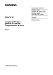
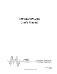
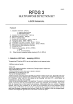
AP-368
APPLICATION
NOTE
82557 10/100 Mbps PCI LAN
Controller
A Guide to 82596
Compatibility
Technical Marketing
Network Products Division
November 1995
Order Number: 644126-001
Information in this document is provided in connection with Intel products. Intel assumes no liability whatsoever, including infringement of any patent or copyright, for sale and use of Intel products except as provided in
Intel’s Terms and Conditions of Sale for such products.
Intel retains the right to make changes to these specifications at any time, without notice. Microcomputer
Products may have minor variations to this specification known as errata.
*Other brands and names are the property of their respective owners.
² Since publication of documents referenced in this document, registration of the Pentium, OverDrive and
iCOMP trademarks has been issued to Intel Corporation.
Contact your local Intel sales office or your distributor to obtain the latest specifications before placing your
product order.
Copies of documents which have an ordering number and are referenced in this document, or other Intel
literature, may be obtained from:
Intel Corporation
P.O. Box 7641
Mt. Prospect, IL 60056-7641
or call 1-800-879-4683
COPYRIGHT © INTEL CORPORATION, 1996
82557 10/100 Mbps PCI LAN CONTROLLER
A GUIDE TO 82596 COMPATIBILITY
CONTENTS
PAGE
1.0 INTRODUCTION ÀÀÀÀÀÀÀÀÀÀÀÀÀÀÀÀÀÀÀÀÀÀÀ 1
2.0 THE 82557 LAN CONTROLLER ÀÀÀÀÀÀÀ 1
3.0 FEATURE CHANGES IN THE
82557 ÀÀÀÀÀÀÀÀÀÀÀÀÀÀÀÀÀÀÀÀÀÀÀÀÀÀÀÀÀÀÀÀÀÀÀ 2
4.0 FUNCTIONAL CHANGES BETWEEN
THE 82557 AND 82596 ÀÀÀÀÀÀÀÀÀÀÀÀÀÀÀÀÀÀ 2
4.1 New Enhancements in the
82557 ÀÀÀÀÀÀÀÀÀÀÀÀÀÀÀÀÀÀÀÀÀÀÀÀÀÀÀÀÀÀÀÀ 2
4.2 Functions in the 82596 Not
Supported by the 82557 ÀÀÀÀÀÀÀÀÀÀÀÀÀÀÀ 3
CONTENTS
PAGE
5.0 SOFTWARE INTERFACE
COMPARISONS ÀÀÀÀÀÀÀÀÀÀÀÀÀÀÀÀÀÀÀÀÀÀÀÀÀ 3
5.1 The 82557 Control Status Register
(CSR) ÀÀÀÀÀÀÀÀÀÀÀÀÀÀÀÀÀÀÀÀÀÀÀÀÀÀÀÀÀÀÀÀÀ 3
5.2 SCB Command Comparisons ÀÀÀÀÀÀÀÀ 7
5.3 SCB Status/Acknowledge
Comparisons ÀÀÀÀÀÀÀÀÀÀÀÀÀÀÀÀÀÀÀÀÀÀÀÀÀ 8
5.4 Action Command Comparisons ÀÀÀÀÀÀ 8
5.5 Configure Parameter
Differences ÀÀÀÀÀÀÀÀÀÀÀÀÀÀÀÀÀÀÀÀÀÀÀÀÀÀÀ 9
5.6 PORT Interface Comparisons ÀÀÀÀÀÀÀ 11
5.7 Statistical/Error Information
Comparisons ÀÀÀÀÀÀÀÀÀÀÀÀÀÀÀÀÀÀÀÀÀÀÀÀ 11
6.0 ADDITIONAL INFORMATION ÀÀÀÀÀÀÀÀ 12
AP-368
1.0
INTRODUCTION
Over the last few years, the networking environment
has evolved to account for the needs of high-bandwidth. Fast Ethernet,* otherwise known as IEEE
100BASE-T, is a technology derived from 10BASE-T
Ethernet and was designed to address many of the performance bottlenecks associated with classic 10 Mbit
Ethernet networks. Intel’s Fast Ethernet component
product solution includes the 82557 and 82553 components.
This application note provides information on the differences between the Intel 82596 and the Intel 82557
next generation family of LAN controllers. It explains
82596 to 82557 compatibility for Ethernet designers.
The application note can help designers transition from
an existing 82596 LAN solution to an 82557 solution.
For further information on the 82557, refer to the
82557 Data Sheet and the 82557 User’s Manual, available from an Intel Sales Representative.
2.0
THE 82557 LAN CONTROLLER
of FLASH provides remote Boot capability (a BIOS
extension stored in the FLASH which could allow a
node to boot itself off of a network drive). For
100 Mbps applications the 82557 contains an IEEE
MII compliant interface to the Intel 82553 physical interface device (or other MII compliant PHY) which
provides a complete LAN solution for 100/10 Mbps
networks. For 10 Mbps networks, the 82557 can be
interfaced to a standard ENDEC interface (such as the
Intel 82503 Serial Interface component), while maintaining software compatibility to 100 Mbps solutions.
The 82557 was designed to implement cost-effective,
high-performance PCI add-in adapters, or it can also be
used directly on a PC motherboard designs. Its combination of high integration and low cost make it ideal for
either application.
82557 Feature Summary
# Glueless 32-bit PCI bus master interface (direct
drive of bus)Ðcompatible to PCI spec Rev 2.1
# 82596-like chained memory structure
# Improved dynamic transmit chaining for enhanced
performance
The 82557 is Intel’s first highly-integrated 32-bit PCI
LAN controller for 10 or 100 Mbps Fast Ethernet networks. The 82557 offers a high performance LAN solution while maintaining low-cost through its high-integration. It contains a high-performance 32-bit PCI Bus
Master interface to fully use the high bandwidth available (up to 132 Mbytes per second) to masters on the
PCI bus. The 82557 is optimized to support
twisted pair Ethernet, the required wiring media for
100BASE-T.
The 82557 contains a number of high-performance networking features that off-load time-critical tasks from
the CPU. Its bus master architecture can eliminate the
‘‘intermediate copy’’ step in Receive (RCV) and Transmit (XMT) frame copies, resulting in faster processing
of these frames. It maintains a similar memory structure to the Intel 82596 LAN Coprocessor, however,
these memory structures have been streamlined for better Network Operating System (NOS) interaction and
improved performance.
The 82557 contains two separate RCV and XMT
FIFOs, preventing data overruns or underruns while
waiting for access to the PCI bus. The FIFOs also enable back to back frame transmission within the minimum inter-frame spacing. Full support for up to 1 Mbyte
# Programmable transmit threshold for improved bus
utilization
# Early receive interrupt for concurrent processing of
receive data
# Built-in FLASH interface with addressing up to
1 MByte
# On-chip receive and transmit FIFOs
# On-chip counters for network management
# Support for back to back transmit interframe spacing (IFS)
# Built in EEPROM interface
# Support for both 10 Mbps and 100 Mbps networks
# Interface to MII-compliant physical interface such
as the Intel 82553 Serial Component for 10/100
Mbps designsÐIEEE 802.3 100BASE-T compatible
# Interface to Intel 82503 for 10 Mbps designsÐIEEE
802.3 10BASE-T compatible
# Autodetect and autoswitching for 10 or 100 Mbps
network speeds
# Full duplex capable at 10 and 100 Mbps
# 160 Lead QFP package
1
AP-368
3.0
FEATURE CHANGES IN THE
82557
The 82557 is a follow-on to the 82596 LAN controller.
Intel made a number of changes and enhancements in
the 82557 to increase performance while being cost sensitive. The following table highlights key functional and
physical changes between the 82557 and 82596:
Feature
82557
Maximum Serial
Speed
10 or 100 Mbps
10 Mbps
82596
MII
Yes
No
Bus Interface
32-Bit PCI
32-Bit Local
Bus
Bus Bandwidth
132 Mbytes/
Sec. @ 33 MHz
106 Mbytes/
Sec. @ 33 MHz
Architecture
Master
Master
Shared Memory
Structures
CSR, CBL, RFA
Initialization
Root, SCB,
CBL, RFA
Transmit/
Receive
Structures
Simplified,
Flexible
82586,
Simplified,
Flexible
Memory
Addressing
32-Bit
Enhanced
Linear
82586, 32-Bit
Segmented,
Linear
FIFO
3K RX, 3K TX
128 Byte RX,
64 Byte TX
Byte Ordering
Little Endian
Little, Big
Endian
FLASH
Interface
Yes (1 M)
No
Package
160-Pin PQFP
132-Pin PQFP,
PGA
Pin Compatible
No
No
Bursting
256 Dword
4 Dword
4.0
FUNCTIONAL CHANGES
BETWEEN THE 82557 AND
82596
This section lists primary functional changes between
the 82557 and the 82596. Some are functional enhancements, others are deletions of the 82596 functionality.
2
4.1 New Enhancements in the 82557
# FIFO size: the 82557 includes independent on-chip
Transmit and Receive FIFOs (3 Kbytes each); the
82596 includes 64 byte transmit and 128 byte receive on-chip FIFOs.
# General chip control structure changes: in the
82557, an on-chip CSR structure incorporates SCB,
Flash/EEPROM and MDI registers. In the 82596,
the shared memory SCB, ISCP, and SCP structures
were used for general chip control.
# Operational speed flexibility: the 82557 supports either 10 or 100 Mbit operation. The 82596 supports a
10 Mbit operation only (ignoring full duplex functionality in both).
# Reset functionality: the 82557 includes a selective
reset command which specifically resets CU and
RU without affecting the overall device configuration. The 82596 includes the CUÐABORT command which terminates the current CU activity and
returns the CU to a known (Idle) state.
# DMA resource tuning: in the 82557, Tx and Rx
DMA preempt counts allow direct manipulation of
DMA resources to reflect design biases towards either transmit or receive functions. The 82596 has a
fixed priority scheme for managing DMA resources.
# Statistical counters: the 82557 contains 16 on-chip
statistical counters that are automatically updated
with each transmit/receive command. The 82596
TCB stores statistical data which must be compiled
by the driver for each TCB before continuing to the
next command.
# MII: the 82557 supports MII interface compatibility
(includes MII specific control and data signals and
MDI register). The 82596 includes a generic
ENDEC serial interface.
# PCI: the 82557 includes a full 32-bit PCI standard
interface. The 82596 includes a 32-bit local bus interface.
# Bus throughput: the 82557 allows a 132 Mbyte maximum parallel (PCI) bandwidth at 33 MHz. The
82596 allows a 106 Mbyte maximum parallel bandwidth at 33 MHz.
# Flash capable: the 82557 allows for a flash memory
interface (control and addressing up to 1 Mbyte).
The 82596 does not allow for designs requiring flash
memory devices.
# Full duplex: the 82557 is truly Full duplex capable
using FDX and FULHAL pins for controlling full
duplex functionality. The 82596 implements a limited full duplex capability.
AP-368
# Adaptive IFS: the 82557 supports an adaptive IFS
algorithm which maximizes network throughput.
The 82596 includes a tunable IFS parameter for
manually adjusting IFS.
# Bursting: the 82557 allows bursting of 256 Dword
lengths. The 82596 allows bursting of 4 Dword
length.
# Early Transmit Completion Status: the 82557 reports a completion of a transmit command as soon
as the frame is copied from memory so that the driver can reuse resources to prepare a new transmit
command.
# Transmit threshold: the 82557 incorporates a transmit threshold parameter which allows adjustment to
the FIFO level at which the Transmit process begins. The 82596 begins the Transmit process as soon
as the first Dword reaches the bottom of the transmit FIFO.
# Addressing modes: the 82557 uses an enhanced linear addressing mode for all operations. The 82596
uses either linear or 32-bit segmented (82586) addressing modes.
4.2 Functions in the 82596 not
Supported by the 82557
5.0
SOFTWARE INTERFACE
COMPARISONS
Both the 82557 and 82596 use a shared memory communication system with the CPU. However, the 82557
uses only three parts that comprise the shared memory
structure: Control/Status Registers (CSR), Command
Block List (CBL), and the Receive Frame Area (RFA).
The 82596 memory structure is divided into four parts:
the Initialization Root, the System Control Block, the
Command Block List, and the Receive Frame Area.
One of the main differences in the 82557 and 82596
memory structures is the 82557 System Control block
(SCB) residing on-chip (accessed by either I/O or
memory cycles) as part of the Control Status Register
(CSR). In the 82596, the channel attention signal is
used by the 82596 to access the System Configuration
Pointer (SCP) and the Intermediate System Configuration Pointer (ISCP). The ISCP then points to the SCB
(see Figure 2). However, the SCB serves the same purpose in both the 82596 and 82557. It is a central communication point for exchanging control and status information between the CPU and the 82557. The CPU
controls the state of the Command Unit (CU) and Receive Unit (RU) (e.g. Active, Suspended or Idle) by
writing commands to the SCB. The 82557 and 82596
updates the SCB Status Word to provide status.
# Byte Ordering: the 82557 supports Little Endian
mode only (no Big Endian mode).
# Addressing: the 82557 has no 82586 compatible addressing modes.
# Adjustable frame length: the 82557 has no Minimum Frame Length variable (82557 has a default
minimum frame length of 64 bytes).
# Monitor mode: the 82557 has no monitoring mode
for evaluating incoming frames.
# Adjustable slot time: the 82557 has no support for
an adjustable slot time parameter.
# Control structures: the 82557 does not include SCP,
SCB or ISCP shared memory structures (on-chip
CSR replaces SCB).
# CRC: CRC flexibility is not supported in the 82557
(No CRC and CRC-16/CRC-32 options are not
present).
5.1 The 82557 Control Status Register
(CSR)
The 82557 CSR registers, MDI, Flash, PORT, MDI
Control, and General Pointer allow the CPU to read to
and from an EEPROM, FLASH, Management Data
Interface (in the case of MDI, Flash, and MDI Control). They also point to various data structures in
memory, reset the 82557, etc. (for General Pointer and
PORT, respectively). In contrast, the 82596 does not
include FLASH or MDI in its SCB; it uses RFA Offset/CBL Offset, as opposed to the 82557 General
Pointer. The 82596 also uses T-ON and T-OFF parameters in its SCB, which the 82557 does not use. Additionally, the 82596 uses the PORTÝ pin to allow the
CPU to directly access it for certain function, as opposed to the 82557, which has a PORT register within
its SCB.
3
AP-368
644216 – 1
Figure 1. 82557 Shared Memory Structure
4
AP-368
644216 – 2
Figure 2. 82596 Shared Memory Structure
5
AP-368
31
Upper Word
ACK
X
CUC
R
16 15
RUC
0
0
0
0
Lower Word
STAT
0
CUS
RFA OFFSET
RUS
0
T
0
0
0
CBL OFFSET
CRC ERRORS
ALIGNMENT ERRORS
RESOURCE ERRORS
OVERRUN ERRORS
RCVCDT ERRORS
SHORT FRAME ERRORS
T-ON TIMER
T-OFF TIMER
Figure 3. 82596 System Control Block
31
Upper Word
16
15
SCB Command Word
Lower Word
0
SCB Status Word
SCB General Pointer
PORT
EEPROM Control Register
Flash Control Register
MDI Control Register
Figure 4. 82557 Control Status Register
The 82557 Command Block List (linked list of individual action commands) and Receive Frame Area (list of
free frame descriptors and data buffers) are very similar
to those of the 82596. Transmit commands can be programmed in either Simplified or Flexible memory
modes. The Receive Frame Area consists of Receive
Frame Descriptors (RFDs) and Receive Buffer De-
6
scriptors (RBDs). The 82596 RFD can be one two
types: Simplified or Flexible. For the 82557, its RFD
can be one of three types: Simplified, Flexible, or Header.
Detailed memory structure differences are highlighted
in Sections 5.2 through 5.7.
AP-368
5.2 SCB Command Comparisons
82557
Type of Command
CPU Acknowledge
Events
Interrupt Control
CU Commands
RU Commands
Other
Op
Code
N/A
Parameter
Acknowledge events are located
in SCB Status word
82596
Op
Code
Parameter
N/A
CX: CU completed action
command
N/A
FR: RU received a frame
N/A
CNA: Command Unit became not
active
N/A
RNR: Receive Unit became not
ready
N/A
N/A (Need external latch)
1
Software Generated Interrupt
1
Interrupt Mask bit
000
NOP
000
NOP
001
CU Start
001
CU Start
010
CU Resume
010
CU Resume
011
Reserved
011
CU Suspend
100
Load Dump Counters Address
100
CU Abort
101
Dump Statistical Counters
101
110
Load CU Base
111
Dump and Reset Statistical
Counters
Load Bus Throttle Timers
Load & restart Bus Throttle Timers
111
Reserved
000
NOP
000
NOP
001
RU Start
001
RU Start
010
RU Resume
010
RU Resume
011
Reserved
011
RU Suspend
100
RU Abort
100
RU Abort
101
Load Header Data Size
101
Reserved
110
Load RU Base
110
Reserved
111
RBD Resume
111
Reserved
N/A
Must use PORT reset
N/A
Reset (logically same as hardware
RESET)
7
AP-368
5.3 SCB Status/Acknowledge Comparisons
Type of Status
82557
Interrupt Acknowledgment
CU Status
RU Status
82596
CX/TNO: CU finished executing a
command with ‘‘I’’ bit set, or
indicates transmit command ended
NOT OK. (configurable)
CX: CU finished executing a
command with its ‘‘I’’ bit set.
FR: RU finished receiving the frame,
or header part of frame.
FR: RU finished receiving a frame.
CNA: Command unit left the Active
state and entered the idle state.
(configurable)
CNA: Command unit left the active
state.
RNR: Receive unit left the Ready
state.
RNR: Receive unit left the Ready
state.
MDI: MDI read or write cycle is
completed. (configurable)
N/A
SWI : Software generated interrupt.
N/A
Idle
Idle
Suspended
Suspended
Active
Active
Idle
Idle
Suspended
Suspended
No Resources
No Resources
Ready
Ready
Suspended with no more RBDs
N/A
No resources due to no more RBDs
No resources due to no more RBDs
Ready with no RBDs present
Ready with no RBDs present
5.4 Action Command Comparisons
Type of Command
Action Commands
8
Op Code
82557
Op Code
82596
000
NOP
000
NOP
001
Individual Address Setup
001
Individual Address Setup
010
Configure
010
Configure
011
Multicast Address Setup
011
Multicast Address Setup
100
Transmit
100
Transmit
101
Reserved
101
TDR
110
Dump
110
Dump
111
Diagnose
111
Diagnose
AP-368
5.5 Configure Parameter Differences
Parameters
Configure Command
Parameters
FIFO/DMA Parameters
Statistical/Error Parameters
IEEE Parameters
Op
Code
82557
010
Op
Code
82596
010
RX FIFO Limit
FIFO Limit
TX FIFO Limit
FIFO Limit
RX DMA Max. Byte Count
N/A
TX DMA Max. Byte Count
N/A
DMA Max. Byte Count Enable
N/A
Save Bad Frames
Save Bad Frames
Discard Short Receive Frames
N/A (use Min. Frame length)
RCV CRC Transfer
N/A
N/A
No CRC Insertion
N/A
CRC-16/CRC-32
N/A
CRC in Memory
N/A
Monitor Bits
N/A
Monitor
Linear Priority
Linear Priority
Interframe Spacing
Interface Spacing
Broadcast Disable
Broadcast Disable
Promiscuous Mode
Promiscuous Mode
Linear Priority Mode
N/A
No Source Address Insertion
No Source Address Insertion
N/A
Backoff Method
N/A
Slot Time
N/A
Maximum Retry Number
N/A
Disable Backoff
N/A
Exponential Priority
9
AP-368
5.5 Configure Parameter Differences (Continued)
Parameters
Collision Parameters
Header Parameters
Other
10
Op
Code
82557
Op
Code
82596
CRS or CDT
N/A
N/A
Carrier Sense Filter
N/A
Carrier Sense Source
N/A
Collision Detect Filter
N/A
Collision Detect Source
N/A
Transmit on no CRS
N/A
Collision Detect by Source
Address Comparison
N/A
Address Length
N/A (use discard short frames)
Minimum Frame Length
Multicast ALL
Multicast ALL
Multiple Individual Address
Multiple Individual Address
N/A
Preamble Until Carrier Sense
Preamble Length
Preamble Length
Adaptive IFS
N/A
Late SCB Update
N/A
Transmit Not OK Interrupt
N/A
CU Idle Interrupt
N/A
Underrun Retry
N/A
503/MII
N/A
Loopback
Loopback
N/A
Manchester/NRZ
Stripping Enable
N/A
Padding Enable
N/A
N/A
Bit Stuffing
N/A
Padding (for Bit Stuffing)
N/A
Auto Retransmit
Byte Count
Byte Count
Force Full Duplex
Full Duplex Operation
Full Duplex Pin Enable
Full Duplex Operation
AP-368
5.6 PORT Interface Comparisons
82557
82596
Software Reset
Software Reset
Self-Test
Self-Test
Selective Reset
N/A (must use CU/RU Abort)
Dump
Dump
N/A
SCP
5.7 Statistical/Error Information Comparisons
82557
Statistical/Error
82596
Location in
Memory/On-Chip
Statistical/Error
Location in
Memory/On-Chip
Transmit Good Frames
on chip counter
N/A
N/A
Transmit Maximum Collisions
Errors
on chip counter
Transmit Maximum Collisions
(number of collisions
experience per frame; used
with Transmit Attempt
Stopped)
in TCB (per frame)
N/A
N/A
Transmit Attempt Stopped
(stopped because number of
collisions exceeded max.
number of retries)
in TCB (per frame)
Transmit Late Collisions Errors
on chip counter/in TCB
Transmit Late Collision
in TCB (per frame)
Transmit Underrun Errors
on chip counter
Transmit Underrun
in TCB (per frame)
Transmit Lost Carrier Sense
on chip counter
Transmit Lost Carrier Sense
in TCB (per frame)
Transmit Deferred
on chip counter
Transmit Deferred
in TCB (per frame)
Transmit Single Collisions
on chip counter
Use Transmit Max. Collisions
Transmit Multiple Collisions
on chip counter
Transmit Total Collisions
on chip counter
Receive Good Frames
on chip counter
N/A
N/A
Receive CRC Errors
on chip counter
Receive CRC Errors
in SCB
Receive Alignment Errors
on chip counter
Receive Alignment Errors
in SCB
Receive Resource Errors
on chip counter
Receive Resource Errors
in SCB
Receive Overrun Errors
on chip counter
Receive Overrun Errors
in SCB
Receive Collision Detect Errors
on chip counter
Receive Collision Detect Errors
in SCB
Receive Short Frame Errors
on chip counter
Receive Short Frame Errors
in SCB
N/A
N/A
Heartbeat Indicator
in TCB (per frame)
N/A
N/A
Transmit lost Clear to Send
in TCB (per frame)
11
AP-368
6.0
ADDITIONAL INFORMATION
For additional literature contact your local Intel sales
office or contact the Intel Literature Center by calling
1-800-548-4725. If you need design information, contact your local Intel Field Applications Engineer.
12