1
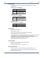
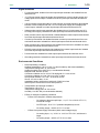
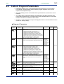
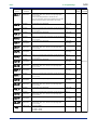
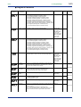
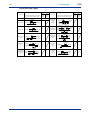
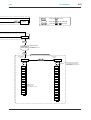
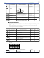
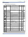
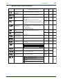
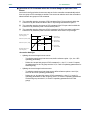
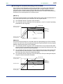
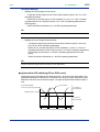
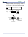
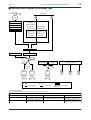
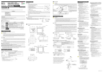
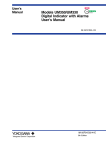
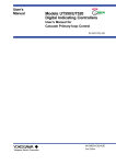
<Toc>
3-22
<3. Programming>
3.8
Program Pattern Setup Charts
See “3.1 Overview of Program Patterns” and “3.2 Example of Program Pattern Setup
Charts” for details on how to use the setting charts.
There are two identical charts shown below because two programs can be registered with
the UP351.
Fill in the fields with bold-face borders in the order of steps 1 to 10, as shown below. Then,
input these setup data items to the UP351.
1. Maximum value of PV input range: Setpoint of the “Maximum Value of PV Input Range (RH)” setup parameter
2. Minimum value of PV input range: Setpoint of the “Minimum Value of PV Input Range (RL)” setup parameter
3. PV input unit: Setpoint of the “PV Input Unit (UNIT)” setup parameter
4. Program time unit: Setpoint of the “Program Time Unit (TMU)” setup parameter
5. Segment setting method: Setpoint of the “Segment Setting Method (SEG.T)” setup parameter
6. Starting target setpoint: Setpoint of the “Starting Target Setpoint (SSP)” program parameter
7. Start code: Setpoint of the “Start Code (STC)” program parameter
8. Junction code: Setpoint of the “Junction Code (JC)” program parameter
9. Target setpoint, Segment time, PV events 1 and 2, and Time event: Setpoint of each program parameter
10. Draw the program pattern.
System name
Program No.
Program time unit (TMU)
Program name
UP351 -
Model
Starting target setpoint (SSP) 6
4
Segment setting method (SEG.T) 5
Serial No.
Unit
Start code (STC)
7
Junction code (JC)
8
10
3
Maximum value of PV input range (RH) 1
100%
Minimum value of PV input range (RL) 2
0%
1
Segment No.
2
3
4
5
6
7
8
9
10
Target setpoint (SP)
Segment time (TM)
9
PV event 1
PV event 2
Time event
Event type (AL1)
Event setpoint (A1)
Event type (AL2)
Event setpoint (A2)
On time of time event (EON)
Off time of time event (EOF)
IM 05E01D12-41E
1st Edition : Jun. 01,2003-00