1
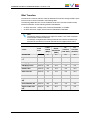
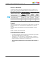
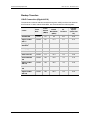
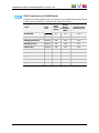
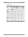
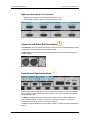
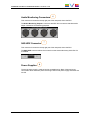
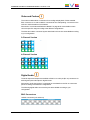
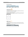
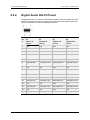
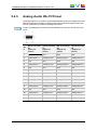
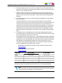
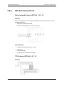
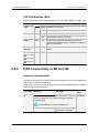
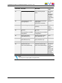
HARDWARE TECHNICAL REFERENCE MANUAL XT3 Server 12.05
Base Board Jumpers
The following table lists the V3X base board jumpers and their respective function:
Jumper
Function
ST1, ST2
These 2 jumpers must be installed on the last V3X board of the server
(that is on V3X #1, 2, or 3 if there are respectively 1, 2, or 3 V3X boards
installed in the server).
ST3 (SPARE)
«Parking» for ST1 and ST2 jumpers when they are not used.
ST4 (only
on V3X
with
genlock)
Must be set to HiZ (or not installed).
Note that the Genlock Loop connector on the back panel of the server (if
available) must always be terminated with a 75 Ohm load if it is not used.
ST5
Defines the position of the board inside the server. It must be set to « 1 »
for a V3X with genlock, and to « 2 » or « 3 » for a V3X board without
genlock, depending on its position in the server.
Base Board LEDs
The table below lists the LEDs available on the V3X base board with the genlock
functionality.
Warning
It is crucial to have a continuous and stable genlock signal when the server is in
operation. In case of interferences on the genlock signal that would cause parity
violations, the recorders will automatically be restarted to maintain data
integrity.
LED
GLK
Color Status
—
Off
Green Blinking
On
Red
PSU
OK
6. Boards Description
Blinking
Function
The genlock module is not initialized.
The genlock module is properly initialized, but no valid
genlock signal is detected.
The module is initialized and a valid genlock signal is
detected.
There is a genlock problem.
On
A resync is needed.
Green
On
All voltages are present and in the allowed range.
—
Off
There is a voltage problem.
87