1
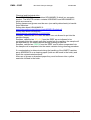
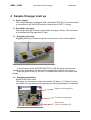
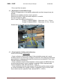
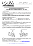
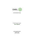
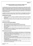
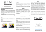
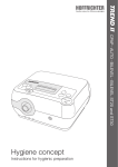
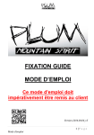
EMBL
SAMPLE CHANGER BioSAXS
ID14EH3
EMBL
ESRF
MANUAL
MAINTENANCE GUIDE
Maintenance guide
EMBL - ESRF
Maintenance guide
Bio-SAXS Sample Changer
25/05/2009
Page 2
EMBL - ESRF
Bio-SAXS Sample Changer
25/05/2009
Maintenance guide
Maintenance guide
Page 3
EMBL - ESRF
Bio-SAXS Sample Changer
25/05/2009
Summary
Maintenance guide ..................................................................................................... 3
1
General informations ........................................................................................... 5
1.1
General description of the BioSAXS sample changer ................................... 5
1.1.1
SEU – Sample exposure unit .................................................................. 5
1.1.2
SCU – Sample changer unit.................................................................... 5
1.1.3
LTU – Liquid transfer unit ........................................................................ 5
1.2
Handling, qualified personnel ........................................................................ 5
1.3 ........................................................................................................................... 6
1.4
2
3
4
Safety ............................................................................................................ 6
Sample Changer start up..................................................................................... 8
2.1
Power supply ................................................................................................. 8
2.2
Pneumatic air supply ..................................................................................... 8
2.3
Engaging electricity ....................................................................................... 8
2.4
Engaging pneumatics .................................................................................... 8
Turning-off the Sample Changer ......................................................................... 9
3.1
Turning-off the electronics ............................................................................. 9
3.2
Turning-off the pneumatics ............................................................................ 9
3.3
Emergency stop............................................................................................. 9
Maintenance off the Sample Changer ................................................................. 9
4.1
Changing the particle filter ............................................................................. 9
4.2
Replacement of the SEU O-rings ................................................................ 10
4.3
Visual control of tubing and safety tray ........................................................ 10
4.4
Needle alignment control ............................................................................. 11
Maintenance guide
Page 4
EMBL - ESRF
Bio-SAXS Sample Changer
25/05/2009
1 General informations
1.1 General description of the BioSAXS sample changer
The BioSAXS sample changer is an instrument installed on a light source
(ID14-EH3 - ESRF) which allows positioning of samples in solution into an Xray beam for scientific analysis.
It is composed of three modules: SEU (sample exposure unit), SCU (sample
changer unit), LTU (liquid transfer unit), plus electronics and the control
software.
1.1.1
SEU – Sample exposure unit
The exposure cell is composed of a removable quartz capillary mounted
under vacuum, which holds the liquid of interest in the X-ray beam,. This
temperature controlled cell is equipped with lighting and a camera system to
enable visualisation of the capillary.
1.1.2
SCU – Sample changer unit
The sample changer allows sample selection by movement in two axes. It
contains a cleaning station with three wells (one contains a detergent
solution, one water and the third dry air).
1.1.3
LTU – Liquid transfer unit
The liquid transfer unit transfers samples from the storage position in the
sample well of the SCU to the measurement position in the capillary of the
SEU. It allows control of the sample position in the capillary and tubing
system. Further peristaltic pumps and venturi aspiration are used to deliver
the cleaning solutions to the cleaning station and to clean the needle,
capillary and all intermediate tubing and connectors of the system.
1.2 Handling, qualified personnel
The sample changers maintenance and service must be done by qualified
personal only.
Any intervention such as repairs (following mechanical or electrical failure),
dismounting and reinstallation of the system or any action which requires
either disconnecting or reconnecting cables and tubing of the sample changer
must only be undertaken by one of the following qualified persons:
FELISAZ Franck
FODINGER Lukas
GIRAUD Thierry
GOBBO Alexandre
HUET Julien
VILLARD Cyril
Maintenance guide
Tel : 7188
Tel : 7951
Tel : 2829
Tel : 7949
Tel : 7714
Tel : 7875
E-mail : [email protected]
E-mail : [email protected]
E-mail : [email protected]
E-mail : [email protected]
E-mail : [email protected]
E-mail : [email protected]
Page 5
EMBL - ESRF
Bio-SAXS Sample Changer
25/05/2009
1.3
1.4 Safety
General: the user is invited to read (on the ESRF homepage) instructions for
effective safety. In particular this concerns among with others: connection of
electrical apparatus, the regulations for using compromised air …
Adhesive labels are placed on some elements of the sample changer. For
your security it is important to follow the indicated instructions; in order to
minimise risks (electrical, chemical ...) to yourself and others.
It is forbidden to remove any fixed safety panels which protect the machine as
well as its users.
The removable Plexiglas safety cover can be removed by the user in order to
load samples into the device. It is equipped with a contact sensor which cuts
the power supply of the SCU motors when it is not in place to protect the user.
During normal use the sample changer can be switched on and off as
described in chapter §2. However, in the case of a problem the device is
equipped with emergency stop buttons:
• The Two emergency stop buttons of the sample changer are
easily accessible: One placed on the marble table (integrated
into the control panel) and one behind the SCU (mounted on the
gray box housing the valves). When activated they cut the
electrical power and pneumatic air supply of the sample changer.
In front of the SCU
Behind the SCU
All ESRF beam lines have emergency stop buttons which can also be used
The beam line emergency stop buttons are placed in the hutch.
Those buttons cut the electrical power, - and pneumatic air supply
for the whole beam line!
ATTENTION !!!! : Activation of these emergency stop buttons cuts
the power and will engage the PSS (safety system) of the whole
beam line, including the other three experimental stations of
ID14!!! Restarting all beamline equipment is a complicated (and
time consuming), so just use it in real emergency.
Maintenance guide
Page 6
EMBL - ESRF
Bio-SAXS Sample Changer
25/05/2009
Chemical and biological risks :
The DETERGENT canister contains HELLMANEX II which is a corrosive
product. The WASTE canister contains KORSOLEX and HELLMANEX II
which are corrosive.
Safety glasses and gloves must be worn (see safety data sheets) to handle
these canisters.
Safety data sheet HELLMANEX II:
www.chem.agilent.com/Library/msds/8529EU.English.pdf
Safety data sheet KORSOLEX :
www.sterillium.com/sida/EN_R10232.PDF
Samples, classified as RED from the ESRF are not allowed to put into the
sample changer.
Samples, classified as YELLOW from the ESRF are not allowed to be
recuperated into the sample well after loaded into the capillary; the sample will
be aspirated into the waste canister during cleaning procedure.
Samples, calcified as GREEN from the ESRF can be ether recuperated into
the sample well or aspirated into the waste canister during cleaning procedure.
If a contamination is determined during the handling of the WASTE canister:
spray KORSOLEX on a cleaning paper (both can be found in the hutch) and
clean the contaminated surfaces.
After use of gloves or absorbent paper they must be thrown into a yellow
waste bin located in the hutch.
Maintenance guide
Page 7
EMBL - ESRF
Bio-SAXS Sample Changer
25/05/2009
2 Sample Changer start up
2.1 Power supply
The sample changer is equipped with a standard CE22 2P+T connector which
is connected to the 240V-50Hz power network with a CEE 7 VII plug.
2.2 Pneumatic air supply
The sample changer is fed by a pneumatic air supply >6 bars. The connector
is a standard fast clip type 8mm (Festo).
2.3 Engaging electricity
Engaging electricity is done using the control panel in front of the machine.
- Turn the rotary switch (POWER SUPPLY) to ON: the green rotary switch
should now be illuminated; the plc and the temperature controller are now on.
- Push the green button (I) 24V ON: to activate the power to the motors and
pumps.
2.4 Engaging pneumatics
Switch on the main valve.
The gauge on the pressure stat must indicate 5.5 bars (+/- 0.5 bars), if that is
not correct turn the pressure stat regulator until the right pressure is indicated.
Pressure stat regulator
Pressure stat gauge
Main valve
(here in position off)
Maintenance guide
Page 8
EMBL - ESRF
Bio-SAXS Sample Changer
25/05/2009
3 Turning-off the Sample Changer
3.1 Turning-off the electronics
The electronic disabling of the sample changer is done by the control panel in
front of the machine.
- Press the red button (0) 24V OFF: to isolate the power to the motors
and pumps.
- Turn the rotary switch (POWER SUPPLY) to OFF: to cut the power
to the automat and temperature controller.
3.2 Turning-off the pneumatics
To turn off the pneumatics close the main valve.
3.3 Emergency stop
The Sample Changer has two emergency stop buttons: one in front of the
machine on the control panel, a second one behind the machine.
To cut the power supply and the pneumatics just press one of this two buttons.
To restart the machine one has to unlock the pressed emergency buttons by
turning it clockwise. Afterwards press the green button (I) 24V ON at the
control panel.
4 Maintenance off the Sample Changer
4.1
Changing the particle filter
For the changing of the filter safety glasses and gloves (both stored in the
hutch) must be worn.
The particle filter (HEPA) should be changed: Every 2 months (i.e. during the
start-up of the beamline after shutdowns)
- Dismount the filter as shown on the following pictures:
- Throw the used filter in one of the yellow DASRI waste bin.
Maintenance guide
Page 9
EMBL - ESRF
Bio-SAXS Sample Changer
25/05/2009
- Put a new filter into place.
4.2 Replacement of the SEU O-rings
The two O-rings shown in the design underneath must be changed every six
months.
Dismount the capillary (see the user’s manual),
Dismount the two O-rings with small callipers or a needle,
Put new O-rings into place.
Note O-rings have different dimensions:
O-ring n°1: Material EP851 – Dimension: 14 x 1 .78 mm
O-ring n°2: Material EP851 – Dimension: 13.10 x 1.8 mm
Grease the O-rings with vacuum grease for a better seal.
Capillary
O-ring n°1 O-ring n°2
4.3 Visual control of tubing and safety tray
Control of the tubing: once a year.
- Visual verification that the two tubes of the peristaltic pumps are in good
condition and do not show sign of fatigue is required. If any fatigue is observed
(even between maintenance periods) the tubes must be replaced (Tube: 3mm
TECAN reference 20725372),
- Visual verification that the tubes between venturi pumps and HEPA filter are
correctly attached and in good condition is required. When required tubes
must be replaced (Tube: silicone ROTH – 9747.1)
- Visual verification that the tube between HEPA filter and the waste canister
is correctly attached and in good condition is essential. If this is not the case
those tubes must be replaced (Tube: silicone ROTH – 9747.1)
Maintenance guide
Page 10
EMBL - ESRF
4.4
Bio-SAXS Sample Changer
25/05/2009
Needle alignment control
Needle alignment check: every two months
- Remove the SCU safety cover,
- Lift the cover plate to its top position (see users guide),
- Put the “SC reference pin” into the third cleaning well (DRY)
- Put the safety cover back in place,
- Use the software application to move the motor X and motor Z to 0,
- Check that the needle points to the marked centre point of the reference pin
- Move the motors back into the default position
- Remove the safety cover again
- Remove the reference pin from the DRY well,
- Detach the cover plate from the holding magnet
- Replace the SCU safety cover
Maintenance guide
Page 11