1
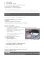
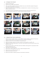
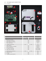
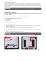
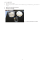
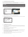
TREND II
Hygiene concept
Instructions for hygienic preparation
CPAP - AUTO - BILEVEL - BILEVEL ST20 and ST30
Contents
1
Symbols in hygiene concept............................................................................................3
2
Safety information............................................................................................................3
3
3.1
3.1.1
3.1.2
3.2
3.3
3.4
Preparation for a patient change......................................................................................4
General.............................................................................................................................4
Reusable products............................................................................................................4
Information when using a bacterial filter..............................................................................4
Delivery, checking and acceptance of devices by service...................................................5
Preparation procedure 1 – Manual preparation...................................................................5
Validated preparation procedure 2 – KR1000 (Keredusy)....................................................5
4
4.1
4.1.1
4.1.2
4.1.3
4.1.4
4.1.5
4.2
4.3
4.4
4.5
4.5.1
4.5.2
4.6
4.7
4.8
4.9
4.10
4.11
4.11.1
4.11.2
4.12
4.13
Preparation . ....................................................................................................................6
Preliminary steps...............................................................................................................6
Protective agents and disinfectants....................................................................................6
Tools, measuring equipment and aids................................................................................6
Unpacking and disinfecting................................................................................................7
Checking for external damage...........................................................................................7
Determining the blower runtime.........................................................................................7
Checking display and contrast...........................................................................................7
Opening the device............................................................................................................8
Dismantling the blower box................................................................................................8
Cleaning and disinfection...................................................................................................9
Device . ............................................................................................................................9
Humidifier........................................................................................................................11
Information about blower box..........................................................................................12
Assembling the device.....................................................................................................12
ADU test and calibration..................................................................................................13
Checking button functions...............................................................................................13
Resetting counters, setting date and time........................................................................14
Device settings................................................................................................................14
Patient-specific device settings........................................................................................14
Resetting device to factory settings.................................................................................14
Checking electrical safety of power supply unit................................................................14
Final steps.......................................................................................................................14
5
5.1
5.2
5.3
5.4
Disposal.........................................................................................................................15
Device and components..................................................................................................15
Packaging.......................................................................................................................15
Batteries..........................................................................................................................15
Accessories and wear parts.............................................................................................15
6
6.1
6.2
6.3
Dispatch instructions for contaminated devices............................................................16
Collection........................................................................................................................16
Packaging for dispatch....................................................................................................16
Dispatch..........................................................................................................................16
-2-
1
Symbols in hygiene concept
Important information is denoted by symbols in this hygiene concept. Be sure to follow these
instructions in order to avoid accidents, personal injury and material damage.
In addition, the local accident prevention regulations and general safety regulations in force in the
area of use must be observed.
This symbol denotes general safety instructions. Follow these instructions to avoid accidents,
personal injury or material damage.
This symbol denotes hazardous situations that may lead to moderately severe injuries.
This symbol denotes information, tips and instructions for the efficient, error-free use of the
device.
2
Safety information
•• Before starting preparation, read this hygiene concept through carefully. Observe
the user's manual and the service manual as well as the warning and safety
instructions they contain.
•• Accessories such as tubing, masks, microfilters etc. are not prepared for a patient
change.
•• Devices used by smokers do not generally undergo hygienic treatment.
•• There is a risk of short-circuiting due to the capacitors present in the device.
•• Hygienic preparation may only be carried out by qualified, authorized and competent specialist personnel.
•• For hygiene reasons, we recommend wearing disposable gloves whenever working on the device. Before further work, the surface of the device must be treated
with a disinfectant. When doing so, observe the manufacturer's safety instructions and instructions for use.
•• If it is necessary to perform work without protective gloves (e.g. final assembly),
hands should be disinfected with hand sanitizer before and after work.
•• When new goods are received by the Service department, the documents supplied with the device must be checked. Devices contaminated with MRSA must
be subjected to hygienic preparation according to the validated KR1000 (Keredusy) preparation procedure. All other devices are prepared according to this
hygiene concept.
•• Special hygiene measures are advisable when performing maintenance or repairs
on devices contaminated with MRSA (methicillin-resistant Staphylococcus
aureus). In this case, protective clothing such as disposable gloves, mask and
disposable apron should be worn without fail. Hygienic preparation according
to the validated KR1000 (Keredusy) preparation procedure must be carried out
before performing maintenance or repair.
-3-
3
Preparation for a patient change
The manual procedure to be used for preparation of the TREND II device for a patient change is
described below. The number of preparation cycles is not limited. This procedure may only be carried out by companies with an appropriately certified quality management system and qualified,
authorized and experienced specialist personnel.
Every repair, service or inspection etc. includes the preparation of devices in the form of surface disinfection.
In the event of device preparation for a patient change, additional disinfection measures are necessary and are described below. This procedure must be observed without fail.
3.1 General
3.1.1 Reusable products
Reusable products (such as tubing, masks, water traps, particle filters etc.) can be disinfected
according to the manufacturer's instructions.
However, these products do not generally undergo preparation at HOFFRICHTER's Service department.
Devices not intended for reuse and – where relevant – other products affected by a patient change
(other medical devices, other accessories, other products) must be packaged separately on return
to the client and identified accordingly as not having undergone preparation.
3.1.2 Information when using a bacterial filter
A bacterial filter is used with respiratory therapy devices and ventilators to filter respiratory air in
order to prevent contamination of the devices. It is connected between the device and the tube system.
Proper use of a bacterial filter (subject to compliance with the service time) while the device is used
on the patient ensures that the patient will be protected from germs.
It is the responsibility of the operator to assess the risk of possible contamination and decide about
the necessity and method of preparation to be used on the device for a patient change.
-4-
3.2 Delivery, checking and acceptance of devices by service
The customer's documents accompanying the device must be checked before commencing preparation. It should be checked whether the dispatch instructions for MRSA-contaminated devices (see
section 6 on page 16) were observed.
The preparation of MRSA-contaminated devices may only be carried out by HOFFRICHTER GmbH
or by other companies certified for this purpose.
Comment:
In the case of devices used solely for stationary applications, where necessary, the operator must
draw up a separate risk assessment depending on the type and level of contamination, define the
method of preparation for use on another patient and specify this in the accompanying documents.
This applies in particular to cases of possible contamination with MRSA or comparable contamination of a device.
3.3 Preparation procedure 1 – Manual preparation
The manual procedure must not be used for the preparation of MRSA-contaminated devices.
This hygienic preparation procedure with a patient change may only be carried out by companies
with an appropriately certified quality management system and appropriately qualified, authorized
and experienced specialist personnel.
Manual preparation is described in this hygiene concept.
3.4 Validated preparation procedure 2 – KR1000 (Keredusy)
The KR1000 (Keredusy) preparation procedure is suitable for the preparation of MRSA-contaminated devices. Other procedures must not be used!
Hygienic preparation with a patient change according to the validated KR1000 (Keredusy) procedure may only be carried out by companies with a QM system and appropriately qualified, authorized and experienced specialist personnel.
The type and scale of the preparation are described in detail in "Instruction on dealing with validated
respirators for the disinfection system KR1000”. The number of preparation cycles for the device is
limited to 5.
-5-
4
Preparation
4.1 Preliminary steps
4.1.1 Protective agents and disinfectants
•• Hand sanitizers: e.g. Sterillium® (Bode)
•• Disinfectant sprays: e.g. Mikrozid® AF Liquid
•• Surface disinfectants: e.g. Mikrozid® AF
•• In the case of medical devices exposed to hazardous contamination (MRSA), additional protective clothing such as disposable gloves, a mask and a disposable apron and goggles should be
worn.
Where possible, wipe disinfection is preferable to spray disinfection.
4.1.2 Tools, measuring equipment and aids
•• Device with power cable (art. no.: 3110 0015)
•• Soft base
•• Two different sizes of Phillips screwdrivers
•• Flow resistor (6 mm) with measuring tube (art. no. 0000 7302)
•• Compressed air spray or stationary compressed air connection
•• Vacuum cleaning device
•• Hygiene service kit (art. no. 0000 2568):
–– 1 complete blower box (replacement for hygienic preparation necessary with patient
change), art. no. 0000 2660
–– 1 sealing gasket for air outlet (art. no. 4210 0938)
–– 1 sealing gasket for humidifier lock lever
(art. no. 4210 0727)
–– 1 pressure measuring tube (art. no. 4500 0014)
–– 1 filter cassette (art. no. 0000 2058)
–– 1 supply slip (label F13-10)
•• PC with following system requirements
(minimum requirements):
–– MS-Windows® XP, Vista or 7
–– AMD Athlon/Pentium class (x86), clock frequency > 700 MHz
Fig. 1:Hygiene service kit
–– 512 MB system memory (recommended)
–– Min. 400 MB free hard drive space
–– Microsoft .NET Framework 2.0 Redistributable (x86)
–– 2 MB graphics card min. High Color (16 bit)
–– Mouse
–– 1 free serial interface + USB port
•• RS232 connecting cable with USB to serial converter (optional)
•• HOFFRICHTER TRENDset PC software (art. no.: 0000 7142)
•• Service manual, user's manual
All tools, measuring equipment and aids possibly exposed to contamination must be cleaned
after they have been used and treated with disinfectant.
-6-
4.1.3 Unpacking and disinfecting
To protect against germs, the surface of the device and, where present, the humidifier must
be treated with a disinfectant immediately after unpacking.
4.1.4 Checking for external damage
Before starting the service, check the device and, where present, the humidifier for external damage.
4.1.5 Determining the blower runtime
If you wish to reuse the old blower box for preparation, you must first determine the motor runtime
of the blower box.
1. Connect the device to the power supply.
2. Use the PC cable to connect the device to the PC.
3. Start the TRENDset PC software and open the connected device under "Found devices".
4. Select the view "Times and Counters".
5. Note down the current blower runtime on the supply slip (label F13-10).
Fig. 2:Label F13-10
4.2 Checking display and contrast
1. Press any key. The display lights up with a brightness of 100 %.
2. Check the display to see whether all characters are shown correctly and complete.
3. The background of the display is illuminated, and the display should be clearly legible in daylight.
4. After 15 seconds the display fades to the basic brightness level selected in the device menu
(0 - 100 %). The display should still be clearly legible.
5. If required, the display contrast can be adjusted with the device open (see service manual).
-7-
4.3 Opening the device
1. Unplug the power plug.
2. Remove the humidifier, where present.
3. Take out the filter cassette and remove the filter frame cover of the filter cassette. Dispose of
the old filter cassette (Fig. 3 and Fig. 4).
4. Place the device top down on a soft base and release the four screws on the housing using a
Phillips screwdriver (Fig. 5).
5. Then stand the device upright again and remove the upper case of the housing (Fig. 6).
6. Remove the design element (Fig. 7) and the button plunger (on/off key).
Fig. 3:
Fig. 4:
Fig. 5:
Fig. 6:
Fig. 7:
Fig. 8:
Fig. 9:
Fig. 10:
Fig. 11:
Fig. 12:
Fig. 13:
Fig. 14:
4.4 Dismantling the blower box
1. Detach all electric cables (DC jack, motor, RS232 connector, heating connector, SD card connector) and the pressure measuring tube from the controller circuit board.
2. Release all screws from the controller circuit board (Fig. 8).
3. Remove the power supply unit and the controller circuit board (Fig. 9 and Fig. 10).
4. Release the 4 Phillips head screws on the cover of the blower box and remove the cover of the
blower box (Fig. 11).
5. Remove the air outlet in combination with the humidifier unlocking button, the pressure switch
and the on/off key (Fig. 12).
6. Dismantle the unlocking button.
7. Remove both sealing gaskets from the air outlet and dispose of them.
8. Remove the motor cable clamp (Fig. 13).
9. Remove the blower box (Fig. 14).
10. Remove the pressure measuring tube from the pressure connection.
-8-
4.5 Cleaning and disinfection
4.5.1 Device
1
9
4
12
2
3
13
5
6
7
10
14
8
11
Component
1
Electronics mounting
2
Spring plates of air outlet
Cleaning
Damp cloth
Compressed air
with mild
and vacuum soapy water
cleaning device
Yes
Disinfection
e.g. Mikrozid© AF
Yes
Optional
Optional
3
Button plunger (on/off key)
Yes
Optional
4
Motor cable clamp
Yes
No
5
Controller circuit board
6
Design element
No
Yes
Yes
No
Optional
7
Contact sockets for humidifier
Yes
Optional
8
Cover for blower box
Yes
Optional
9
Top section of housing
Yes
Yes, partially
10 Upper case of housing
Yes
Yes, partially
11 Measuring tube connection
No
Yes
Yes
12 Filter frame cover
Yes
Yes
13 Air outlet
Yes
Yes
14 Humidifier unlocking button
Yes
Yes
-9-
Information about cleaning
All components, with the exception of the circuit boards, can be cleaned using a damp cloth and
a solution of soapy water in a standard concentration. Use compressed air to clean the controller
circuit board and areas which are not readily accessible and remove loose particles with a vacuum
cleaning device.
Allow components to dry completely in the air before assembling the device.
Information about disinfection
All components acting as air ducting must be treated with a disinfectant. Components which act as
air ducting include:
•• Filter cassette area of upper case of housing (see Fig. 15 [a])
•• Filter cassette area of lower case of housing (see Fig. 16 [b])
•• Measuring tube connection (see Fig. 16 [c])
•• Filter frame cover
•• Air outlet
•• Humidifier unlocking button
Carry out disinfection as follows:
1. Apply disinfectant spray to the components. In area of the measuring tube connection, spray
directly into the opening.
2. Allow the disinfectant to act according to the manufacturer's instructions.
3. Turn over the upper and lower cases of the housing after spraying to allow the disinfectant to
run off.
4. Remove any residue with a dry dust-free cloth.
Allow components to dry completely in the air before assembling the device.
a
b
c
Fig. 15:Upper case of housing
Fig. 16:Lower case of housing with measuring tube connection
- 10 -
4.5.2 Humidifier
1. Dismantle the humidifier.
2. Remove any limescale residue from the humidifier using a mild descaler (e.g. 5 % solution of
vinegar).
3. Wash out the humidifier thoroughly.
4. Disinfect the humidifier.
Fig. 17:Cleaning and disinfection of humidifier
- 11 -
4.6 Information about blower box
In the course of hygienic preparation you can either fit a new blower box from the hygiene kit or
send in the old blower box for preparation to HOFFRICHTER GmbH.
Preparation of the blower box may only be carried out by HOFFRICHTER GmbH. Preparation
may only take place when the blower runtime < 7000 hours, and the device is not contaminated with nicotine.
1. Fill out the label F13-10 (see Fig. 18) to document the blower runtime and affix to the blower
box (see Fig. 19). Also copy the data to your records.
Fig. 18:Label F13-10
Fig. 19:Affixing the label F13-10
2. Send in the blower box for preparation to HOFFRICHTER GmbH.
3. HOFFRICHTER will then return the hygienically prepared blower box. The blower box displays
the label F13-06 (see Fig. 20).
Fig. 20:Label F13-06
4.7 Assembling the device
1. When installing a new blower box, enter the serial number of the new box in the repair order.
2. Fit the pressure measuring tube from the hygiene service kit onto the connection for the pressure measuring tube.
3. Insert the blower box into the lower case of the housing.
4. Position the motor cable and align carefully.
5. Fit the motor cable clamp.
6. Slide the sealing gasket for the humidifier lock lever (gray) and then the sealing gasket for the
air outlet (black) from the hygiene service kit onto the air outlet.
7. Press the humidifier unlocking button onto the air outlet. The unlocking button should then
snap into place behind the brackets.
8. Apply a thin layer of OKS1110 multi-silicone grease to the rear of the air outlet.
9. Fit the air outlet and the on/off key.
- 12 -
10. Position the cover for the blower box. Fix the cover for the blower box in place with the 4 Phillips head screws.
11. Position the controller circuit board and fix the circuit board in place using the 5 screws.
12. Insert the power supply unit.
13. Connect all electric cables (DC jack, motor, RS232 connector, heating connector, SD card connector) and the pressure measuring tube to the controller circuit board and check for secure
positioning. Check that all cables and tubing are protected from tension, compression and
clamping.
14. Insert the design element.
15. Fit the button plunger and the on/off key.
16. Fit the upper case of the housing onto the lower case and turn the device over.
17. Use the 4 Phillips head screws to fix the upper case of the housing to the lower case.
18. Insert a new filter cassette into the filter frame cover.
19. Insert the filter frame cover with the new filter cassette into the device.
4.8 ADU test and calibration
Carry out the ADU test and, if necessary, calibration according to the TREND II service manual.
4.9 Checking button functions
1. Check that the blower switches on and off properly when the on/off key is pressed.
2. Check that all keys function properly. They must not jam and should return to their original
position after being pressed.
3. Insert the humidifier until it perceptibly clicks into place. Release the mechanism by pressing
the unlocking button and then detach the humidifier again. It should be possible to attach and
detach the humidifier with little effort.
4. When the humidifier is attached, press the heating key on the display to check that the
selected heating level is indicated and that the LED lights up.
- 13 -
4.10 Resetting counters, setting date and time
1. Use the PC cable to connect the device to the PC.
2. Start the TRENDset PC software and open the connected device under "Found devices".
3. Select the view "Times and Counters".
4. Reset the filter counter.
5. Reset the blower runtime.
6. Reset the date and time, if necessary.
7. Click on "Send".
4.11 Device settings
4.11.1Patient-specific device settings
1. If you have new patient data, select the view "Patient Data".
2. Enter the new patient data.
3. Click on "Send" to store the settings in the device.
4. Select the view "Device Settings".
5. Select the device settings.
6. Click on "Send" to store the settings in the device.
4.11.2Resetting device to factory settings
1. If you do not have any patient data or patient-specific device settings, reset the device to the
factory settings.
2. Select "Communication > Delete Device Data > Delete Device Memory and Send Factory Settings".
4.12 Checking electrical safety of power supply unit
The device is equipped with protective insulation, and only the power supply unit has to be checked
for electrical safety. In the course of automatic checking by a device safety tester, the power supply
unit is tested according to VDE 0751-1 / DIN EN 62353:2008 as a power supply unit belonging to
protection class II. The probe used to measure the device leakage current is connected to the GND
of the DC input. This is electrically connected to the secondary side of the power supply unit.
4.13 Final steps
After finishing work, perform wipe disinfection of external surfaces.
After finishing the preparation work, draw up a final report and affix a test seal showing the date and
tester's initials to a suitable position on the device.
Until dispatch, store the device and blower box safely away from soiling and contamination from
human pathogens by placing in a sealed tear-proof plastic bag.
- 14 -
5
Disposal
Proper disposal saves natural resources and prevents harmful substances being released into the
environment.
5.1 Device and components
The device and its electronic components must not be disposed of with household waste. They
must be disposed of at a communal collection point or public waste disposal authority.
5.2 Packaging
Packaging may be disposed of with normal household waste or at a communal collection point.
5.3 Batteries
Batteries must not be disposed of with household waste. They must be returned to the distributor
or disposed of at a communal collection point.
5.4 Accessories and wear parts
Disposal of accessories such as tubing, mask, filter cassette and wear parts (e.g. sealing gaskets)
and other replaced components must be carried out according to the statutory provisions in force
at the area of use. This also applies to contaminated accessories.
- 15 -
6
Dispatch instructions for contaminated devices
The dispatch instructions apply to contaminated medical devices delivered to
HOFFRICHTER GmbH for preparation.
6.1 Collection
The contaminated medical device is collected from the patient by the distributor, medical technician
or authorized personnel. This involves on-site surface disinfection of devices and accessories with
Mikrozid Liquid Spray (MRSA-active), followed by careful bagging while wearing disposable gloves,
a mask and a disposable apron. The proper disposal of non-reusable materials according to the
regulations must be ensured.
6.2 Packaging for dispatch
The distributor or Service departments packages the device/accessories in sterile welding film, followed by heat-sealing or packaging in PVC or PE bags (tear-proof) closed off with tape or cable
ties.
Power cables, therapy accessories, user's manual and other accessory articles with a minimal risk
of infection must be disposed of according to the regulations.
Note:"ATTENTION – CONTAMINATED DEVICE" or
"ATTENTION – MRSA-CONTAMINATED DEVICE"
must be clearly displayed in the packaging.
The packaging should be sturdy and of the correct type and must not be contaminated. Cardboard
boxes must be carefully sealed with packing tape.
6.3 Dispatch
The delivery note must be affixed to the outer packaging of the device.
(delivery note to state: "ATTENTION – CONTAMINATED DEVICE" or "ATTENTION – MRSA-CONTAMINATED DEVICE"). Shipment is effected via logistics companies.
HOFFRICHTER GmbH
Mettenheimer Strasse 12 / 14
19061 Schwerin
Germany
Phone: +49 385 39925 - 0
Fax:
+49 385 39925 - 25
E-mail: [email protected]
www.hoffrichter.de
TREND II-hygiene-eng-220911-02
- 16 -