1
3 - Connecting to your application board
3.7
ST7MDT20-DVP3 Probe User Guide
Installing HE10 connectors on your application board
This section provides information about installing connectors on your application
board for the connection with your emulator. Doing this will allow you to connect
your emulator to the application board without using the device adapters and/or
sockets described in the preceding sections. To do this you can install connectors
on your application board that correspond to W1 and W2 connectors of the DB530
adapter, or to the 50-pin flat cable connectors.
Whichever option you choose, you will have to orient all connectors correctly and
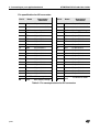
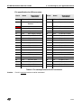
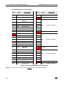
ensure the necessary pin connections according to the specifications provided in
this section.
3.7.1
Orientation of the connectors
To receive the DB530 flat cable adapter
When designing your application board with the 40-pin, SAMTEC connectors
corresponding to W1 and W2 on the flat cable adapter, be sure to orient them
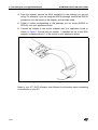
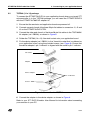
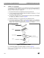
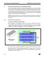
correctly. The schematic in Figure 15 shows the orientation of the W1 and W2
connectors in relation to the adapter’s J1, J2 and J3 connectors.
1400 mils
(35.65 mm)
DB530 Adapter
(top view)
Figure 15: Orientation of J1 and J2 connectors
W1 and W2 on this adapter are SAMTEC connectors (REF.: TFM 120-22-S-D-A).
When installing the corresponding connectors to receive the W1 and W2
connectors, you must ensure a distance of 1400 mills between the connectors,
measured as shown in Figure 15.
22/38