1
Freescale Semiconductor
Application Note
Document Number: AN2929
Rev. 0, 11/2005
Automatic Thermal Monitoring
System on HPC II
by
Brandon Ade
Digital Systems Division
Freescale Semiconductor, Inc.
Austin, TX
1
Introduction
This application note applies to the MPC7447A and
MPC7448 processors embedded on an HPC II platform. It
describes the implementation of an Automatic Thermal
Monitoring System (ATMS), used to automatically control
the processor core temperature. When activated, the ATMS
cools the processor by two methods: CPU fan control and
CPU frequency throttling, known as Dynamic Frequency
Switching (DFS). The benefits of implementing an ATMS
system are threefold: it reduces power consumption, reduces
noise, and provides a fail-safe mechanism that powers off the
system in the event of extreme operating temperatures.
The following section descriptions provide an overview of
this document.
Section 2, “Functional Overview,” provides a top-level view
of the ATMS and how the on-board hardware interfaces and
communicates.
Section 3, “Functional Philosophy,” describes the major
functional components of the ATMS.
© Freescale Semiconductor, Inc., 2005. All rights reserved.
Contents
1. Introduction . . . . . . . . . . . . . . . . . . . . . . . . . . . . . . . . . 1
2. Functional Overview . . . . . . . . . . . . . . . . . . . . . . . . . . 2
3. Functional Philosophy . . . . . . . . . . . . . . . . . . . . . . . . 3
3.1.Calibration on Startup . . . . . . . . . . . . . . . . . . . . . . . 4
3.2.System Interrupts . . . . . . . . . . . . . . . . . . . . . . . . . . 7
4. DINK32 on HPC II Board . . . . . . . . . . . . . . . . . . . . 10
4.1.Environment . . . . . . . . . . . . . . . . . . . . . . . . . . . . . 10
4.2.Command Line Interface . . . . . . . . . . . . . . . . . . . 11
5. Conclusion . . . . . . . . . . . . . . . . . . . . . . . . . . . . . . . . 15
6. References . . . . . . . . . . . . . . . . . . . . . . . . . . . . . . . . . 15
7. Revision History . . . . . . . . . . . . . . . . . . . . . . . . . . . . 16
A. Ideality Factor Determination . . . . . . . . . . . . . . . . . . 17
B. Pseudocode . . . . . . . . . . . . . . . . . . . . . . . . . . . . . . . . 19
Functional Overview
Section 4, “DINK32 on HPC II Board,” gives some kernel specific instructions for those operating under
DINK32 on a HPC II development board.
Section 5, “Conclusion,” gives closing remarks.
Section 6, “References,” provides a list of references.
Section 7, “Revision History,” gives the revision history for this document.
Appendix A, “Ideality Factor Determination,” details the methodology used to determine the ideality
factor of the CPU thermal diode.
Appendix B, “Pseudocode,” contains verbose pseudocode for all of the functions that comprise the ATMS.
2
Functional Overview
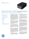
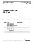
Figure 1 shows a simplified block diagram of the ATMS. The ATMS is possible by way of the thermal
diode which resides on the processor die. A temperature reading can be determined by measuring the
change in the base-emitter voltage (VBE) of the diode when operated at different currents. The resulting
∆VBE measurements can then be digitized and a die junction temperature produced. In this implementation
a thermal monitor chip ADT7461 was used to read the diode temperature. Standard A/D can be used
whereby exploiting the negative temperature coefficient of the diode can be used to measure VBE.
However, this method would require a non-trivial amount of calibration due to a number of factors. For
example, parasitic series resistance with the remote diode appears as a DC offset. This introduces an error
factor in the temperature reading seen as a number of °C per ohm of parasitic resistance (°C/Ω). The
absolute value of VBE, which varies from device to device, also appears as a constant temperature offset.
For these reasons, specialized devices which can automatically compensate for many or all of these factors
are typically used. Otherwise these errors must be compensated for in software.
The main function of the Thermal Sensor within the ATMS is to interface with the thermal diode to
produce a temperature reading. The ADT7461 is a dual-channel digital thermometer and under/over
temperature alarm. It provides the extra benefit of two temperature limit flags, namely THERM and
ALERT/THERM2. These flags are asserted when either a THERM limit or a Temperature High/Low limit
is exceeded; both of these limits are user programmable. The THERM flag translates to THERM_ALARM
in the FPGA (Actel ProASICPLUS) which in turn asserts the system interrupt INT[1] to the bridge chip
(Tsi108). ALERT/THERM2 translates to OVER_ALARM in the FPGA which in turn produces the system
interrupt INT[0]. The bridge chip is responsible for then asserting an interrupt (INT) to the CPU. These
two interrupts provide the automatic capability of the ATMS, enabling system interrupts and the ATMS to
generate interrupts at key temperature thresholds and perform the action necessary to cool the system, all
without any user interaction. The reads and writes to the thermal sensor are done through an I2C bus or
similar protocol (that is, SMBus). Note that while two interrupt lines were available in this specific
implementation, it is possible to implement the ATMS with only one interrupt line. In the one interrupt line
case, software would need to determine what caused the interrupt (possibly by reading registers in the
FPGA), and after the cause was determined would then need to take the appropriate action.
Automatic Thermal Monitoring System on HPC II, Rev. 0
2
Freescale Semiconductor
Functional Philosophy
NOTE
Freescale makes no recommendations about the components used in this
design. Similar components from other vendors provide similar results. The
remainder of this application note details the setup used in Freescale’s DSD
Applications Lab.
I2C Bus
SCL
SDA
Bridge Chip
(Tsi108)
FPGA
(Actel ProASICPLUS)
INT0
XINT0
INT1
XINT1
THERM_ALARM
OVER_ALARM
Thermal Sensor
(ADT7461)
CPU
(MPC7448)
DXP
TEMP_ANODE
DXN
TEMP_CATHODE
THERM
ALERT/THERM2
INT
CPUINT0
Figure 1. Functional Block Diagram of ATMS
3
Functional Philosophy
The three main operations covered in this application note are as follows:
1. Calibration of the ATMS using environment variables
2. Command line options of the ATMS
3. System interrupts
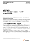
Figure 2 shows the structure of the code that controls the ATMS, broken into the three main components
of the system. The italicized functions are those that pertain specifically to the ATMS. The file main.c
contains the main() loop for the kernel. In this implementation the kernel is Freescale’s Dynamic
Interactive Nano Kernel for 32-bit processors (DINK32), which is publicly available under license from
Freescale. During boot up DINK32 initializes the environment which makes calls to the ATMS specific
functions adt7461_init() and fan_init(), described in detail in Section 3.1, “Calibration on Startup.” The
file gme.c contains a number of device operations and command line processing for DINK32, and
specifically to the ATMS, contains the code to handle the command line options available to interface and
calibrate the ATMS. These functions are described more thoroughly in Section 4.2, “Command Line
Interface.” The file mpic1.c is the interrupt handler for DINK32. It is responsible for initializing the ATMS
when system interrupts are enabled as well as for calling the proper interrupt handler for the THERM and
ALERT/THERM2 flags when they are asserted. The ATMS specific functions ISR_INT0(), ISR_INT1(),
Automatic Thermal Monitoring System on HPC II, Rev. 0
Freescale Semiconductor
3
Functional Philosophy
and adt7461_interrupt_init() provide the automatic interrupt functionality and are described in more
detail in Section 3.2, “System Interrupts.”
Command Line Options
Calibration with
Environment Variables
gme.c
main.c
par_ct ()
main ()
par_dt ()
par_gme ()
dink_initialize ()
ct_exec ()
dt_exec ()
check_limits ()
print_adt7461_registers ()
env.c
adt7461_init ()
Interrupts
fan_init ()
mpic1.c
mpicInit ()
adt7461_interrupt_init ()
mpicISR ()
ISR_INT0 ()
ISR_INT1 ()
Figure 2. Function Hierarchy of ATMS Software
3.1
Calibration on Startup
On system boot up the ATMS is calibrated by writing to the Thermal Sensor registers. The function
adt7461_init() handles making the initial writes on the I2C bus to calibrate the Thermal Sensor. Table 1
gives the register values for this specific implementation of the ATMS. Again, these values are user and
system specific and with different preferences, or devices, will change accordingly. See ADT7461 ±1°C
Temperature Monitor with Series Resistance Cancellation Specification, for further details about these
registers.
Table 1. Initial Register Writes to Thermal Sensor (ADT7461) on Boot Up
Register
Name
Write Address
(Hex)
Power-On
Default
Written Value at Boot Up
(Hex)
Configuration
09
0x00
if (Disable7461 == 0)
0xA0
if (Disable7461 == 1)
0xE0
Disable7461 is a global variable that is assigned based
on the current ATMS status. It is 0 if the ATMS is
enabled and 1 if the ATMS is disabled.
Conversion
Rate
0A
0x08
0x07 (8 c/s)
At 8 Conversions/Second the ADT7461 does its own
internal averaging.
At > 8c/s no averaging is done.
Local Temp
High Limit
0B
0x55
if (CPU == MPC7447A)
0x34 (52°C)
if (CPU == MPC7448)
0x2C (44°C)
Reason
Same as CPU core temperature limit.
Automatic Thermal Monitoring System on HPC II, Rev. 0
4
Freescale Semiconductor
Functional Philosophy
Table 1. Initial Register Writes to Thermal Sensor (ADT7461) on Boot Up (continued)
Register
Name
Write Address
(Hex)
Power-On
Default
Written Value at Boot Up
(Hex)
Local Temp
Low Limit
0C
0x00
0x00 (0°C)
Ext Temp High
Limit High Byte
0D
0x55
if (CPU == MPC7447A)
0x34 (52°C)
if (CPU == MPC7448)
0x2C (44°C)
Ext Temp Low
Limit High Byte
0E
0x00
0x00
Ext Temp
Offset High
Byte
11
0x00
if (CPU == MPC7447A
AND TOFFSET == NULL)
0x00
if (CPU == MPC7448 AND
TOFFSET == NULL)
0xFC (-4°C)
if (TOFFSET != NULL)
TOFFSET
Ext Temp
Offset Low
Byte
12
0x00
0x00
0.25° decimal precision is not used in this
implementation.
Ext Temp High
Limit Low Byte
13
0x00
0x00
Unchanged
Ext Temp Low
Limit Low Byte
14
0x00
0x00
Unchanged
External
THERM Limit
19
0x55
0x55 (85°C)
Unchanged
Local THERM
Limit 1
20
0x55
0x55 (85°C)
Unchanged
THERM
Hysteresis
21
0x0A
if (CPU == MPC7447A)
0x04 (4)
if (CPU == MPC7448)
0x05 (5)
These values were derived from DSD applications lab
testing. Table 2 gives the results of this testing. The
desired value is one that reduces power consumption,
overall noise, and still properly controls the
temperature.
Consecutive
ALERT
22
0x01
0x00
Since the critical overheat temperature is set to 100°C
by default, it is desirable to have this interrupt trigger
immediately since it is unlikely to occur twice before the
CPU reaches its maximum temperature rating.
1
Reason
Unchanged
During applications lab testing with a MPC7447A,
52°C (0x34) was the peak temperature the CPU
reached when powered on without strenuous code
execution.
For the MPC7448 this value was 44°C (0x2C).
Note: These thermal limits are system and processor
specific.
Unchanged
TOFFSET is an environment variable that is checked
on bootup. If TOFFSET is defined then its value is used
as the DC offset value applied to the Thermal Sensor.
If TOFFSET is not defined then a default value is
written based on CPU type. The MPC7447A was not
tested for this in the DSD applications lab so this
specific implementation uses the ADT7461 default of
zero. However, it is recommended that the worst case
ideality factor, given in the hardware specification, be
used to determine the default DC offset.
“Local” temperature limits refer to the internal temperature monitor of the ADT7461, “external” limits refer to temperatures read
from the CPU thermal diode.
Automatic Thermal Monitoring System on HPC II, Rev. 0
Freescale Semiconductor
5
Functional Philosophy
Note: the ATMS monitors both local and external limits. Therefore if the ambient temperature around the ADT7461 reaches any
of the temperature thresholds the corresponding interrupts will be triggered as if the temperature was read from the CPU
thermal diode.
Table 2. Number of Interrupt Calls Versus Hysteresis Values
Hysteresis Effect on MPC7447A with External and Local Temperature
Thresholds set to 0x34 (52°C)
DC Offset: 0°C
Hysteresis Value
Length of Test (min)
# INT Calls Minutes / Call
Calls / Min
0x00
4
236
0.017
59.000
0x01
14
18
0.778
1.286
0x02
20
11
1.818
0.550
0x03
100
47
2.128
0.470
0x04
1020
211
4.834
0.207
0x05
120
1
120.000
0.008
Hysteresis Effect on MPC7448 with External and Local Temperature
Thresholds set to 0x2C (44°C)
DC Offset: –4°C
Hysteresis Value
Length of Test (min)
# INT Calls Minutes / Call
Calls / Min
0x00
1
59
0.017
59.000
0x01
17
16
1.063
0.941
0x02
28
15
1.867
0.536
0x03
53
19
2.789
0.358
0x04
92
20
4.600
0.217
0x05
83
8
10.375
0.096
Four environment variables directly affect the ATMS setup: TOFFSET, FANPWM, TDISABLE, and
TSHUTDOWN.
TOFFSET allows for individual systems to be calibrated after a specific ideality factor is found for that
system. This environment variable sets the DC offset of the Thermal Sensor, which is then automatically
applied on every temperature read. If this variable is not set then a default DC offset is assigned depending
on processor type. If the ideality factor (nf) of a device is defined in the hardware specification then use
that value to determine the default DC offset. Use Equation 1 in Appendix A, “Ideality Factor
Determination,” to directly find this DC offset given nf. However, if an nf value is not known or a more
specific nf value is required, Appendix A outlines a methodology to determine the nf and DC offset for a
specific device. Testing done on a MPC7448 processor in the DSD applications lab found an overall
average temperature reading of 4.32° above expected, corresponding to a value of –4°C as the default DC
offset for this implementation. This value of –4°C is applied as a default when TOFFSET is not defined
for a MPC7448.
Automatic Thermal Monitoring System on HPC II, Rev. 0
6
Freescale Semiconductor
Functional Philosophy
FANPWM, if defined, is used as the fan speed when the ATMS is enabled and no thermal thresholds have
been exceeded. If FANPWM is not defined, then a default value of 50% is used for the fan speed when the
ATMS is idle and no thresholds have been reached. FANPWM also provides the user the ability to control
the CPU fan speed regardless of the ATMS status. Whether the ATMS is enabled or disabled, FANPWM
can be defined to set the fan speed on boot up. Note that when the ATMS is enabled, the fan speed is set
to 100% when the first thermal threshold is reached (THERM2).
TDISABLE disables/enables the ATMS. If this environment variable is set to “1” then the ATMS is
disabled. When disabled the Thermal Sensor is put in standby mode and no longer makes temperature
conversions. System interrupts can also be enabled as these will be ignored by the ATMS when it is
disabled. When the ATMS is disabled the CPU fan speed reverts back to the FANPWM environment
variable. If this environment variable is not defined the fan is set to 100%.
TSHUTDOWN sets the critical temperature shutdown limit of the ATMS on boot up. This environment
variable is part of the fail-safe feature of the ATMS. It guarantees that at a predefined temperature the
system will shut down. If TSHUTDOWN is not defined then a default value of 100°C is used as the critical
temperature limit.
The function adt7461_init() calibrates the ATMS and the function fan_init() initializes the fan speed
settings using FANPWM. Appendix B, “Pseudocode,” contains commented pseudocode for both of these
functions.
3.2
System Interrupts
Interrupts provide the ‘automatic’ capability of the ATMS. As mentioned in Section 2, “Functional
Overview,” threshold flags sent from the Thermal Sensor are translated to system interrupts, namely
INT[0] and INT[1]. The operation of these interrupts and the thermal thresholds that trigger them are
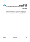
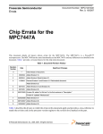
shown in Figure 3. Following Figure 3 is a description of what occurs at each edge trigger. Figure 4 is a
flowchart showing how the interrupts operate. The parenthesized numbers in the flowchart correspond to
the numbered trigger points in Figure 3.
During the design process it was decided that DFS mode will be enabled at the first THERM threshold,
but will not be disabled when the temperature drops below this theshold. Instead, DFS mode is kept on
until the temperature drops passed the THERM2 trigger limit. Also, during the first INT[1] interrupt call
(see point 2 in Figure 3) the THERM limits inside of the Thermal Sensor are changed to the environment
variable TSHUTDOWN, if this variable is defined. If TSHUTDOWN is not defined then the THERM
limits are changed to a default of 0x64 (100°C). This ensures that if the temperature continues to increase
to the critical temperature limit the INT[1] interrupt will still be triggered on a falling edge and a system
shut down can occur, providing the fail-safe functionality of the ATMS. Note that this system shut down
temperature can be other than 100°C by simply defining the TSHUTDOWN environment variable.
Note that in the HPC II design example, temperatures and THERM limits lower than 0°C were not
considered. See the ADT7461 data sheet for a more detailed description of how the temperature limit
interrupts work and how they could be used in other implementations.
The interrupt vectors 0 and 1 are initialized in the function adt7461_interrupt_init() when the system
interrupts are enabled. If the ATMS is disabled, by way of the “ct –d” command or from the TDISABLE
environment variable, then the ATMS interrupts will still be initialized but will not be active. After
initialization the interrupt service routines responsible for handling the THERM and THERM2 triggers are
Automatic Thermal Monitoring System on HPC II, Rev. 0
Freescale Semiconductor
7
Functional Philosophy
ISR_INT1() and ISR_INT0() respectively. Pseudocode for these functions can be found in Appendix B,
“Pseudocode.”
3a
100°C
100°C /
TSHUTDOWN
System
Shut Down
90°C
THERM Limit
80°C
Temperature
DFS ON
INT1
Triggered
3b
70°C
60°C
50°C
THERM2 Limit
INT0
Triggered
40°C
Fan: 100%
30°C
THERM2
THERM
Fan: 50% /
FANPWM
DFS OFF
4
1
2
3
1. When the THERM2 limit is exceeded, the THERM2 signal asserts low. INT0 is triggered and
the fan is set to 100%.
2. If the temperature continues to increase and exceeds the THERM limit, the THERM output
asserts low. INT1 is triggered and DFS mode is enabled. The THERM limits are overwritten
with the critical temperature limit (100°C or TSHUTDOWN if defined).
3. a. If the temperature continues to increase and exceeds the second THERM limit (critical
temperature limit), the THERM output asserts low. INT1 is called a second time and the
system shuts down.
b. If the temperature does not reach the critical temperature limit, then no action is taken.
4. As the system cools down, and the temperature falls below the THERM2 limit minus
hysteresis (in this case it is set to zero), the THERM2 signal resets (goes high). INT0 is
called, the fan is set to FANPWM if defined (else 50%), and DFS mode is disabled.
The THERM limits are also reset to their previous values (default 0x55).
Figure 3. Operation of the THERM and THERM2 Interrupts
Automatic Thermal Monitoring System on HPC II, Rev. 0
8
Freescale Semiconductor
Functional Philosophy
Interrupt
Received
INT
Vector 0 Triggered
by THERM2
?
Yes
INT
Vector 1 Triggered
by THERM
?
No
Yes
ISR_INT0
Called
THERM2
Falling Edge
?
Yes (1)
ISR_INT1
Called
Call Other
Interrupt Handler
Set Fan Speed to 100%
Critical
Temperature
Reached
?
No (4)
FANPWM
Defined
?
Yes
No
Set Fan Speed to
FANPWM
No (2)
Yes (3)
System
Shut Down (3a)
No
Set Fan Speed to 50%
DFS
Enabled
?
No
Enable DFS,
Set THERM Limit =
TSHUTDOWN / 100°C
Yes
Disable DFS, Set
THERM Limit = 85°C
Return from
Interrupt
Figure 4. Interrupt Handler Flowchart
Automatic Thermal Monitoring System on HPC II, Rev. 0
Freescale Semiconductor
9
DINK32 on HPC II Board
4
DINK32 on HPC II Board
When operating under the DINK32 kernel on a HPC II development board the following sections can be
used for debug and test purposes. At the DINK32 command prompt, typing “env ?”, “ct ?”, or “dt ?”
displays a help screen for the environment variables command, the configure temperature command, or
the display temperature command respectively.
Table 3 outlines the references that were used during development of the ATMS. These are specific to the
MPC744X line of processors and the HPC II development board, but will provide a greater understanding
of how the ATMS was developed.
Table 3. References Used in ATMS Development
Reference
4.1
Used During
[1]
...all stages of the ATMS development.
[4]
...development of the interrupt handlers and when modifying the HID1 register. Specifically see section 2.2.5.2.
[5]
...development of the interrupt handlers. Specifically for information on TICK registers that controlled fan speed,
power off ability, and interrupt initialization. See section 6.
[6]
...development of interrupt handlers and when modifying the HID1 register. Provided information about PLL bits
contained within the HID1 register. See section 9.1.1.
[7]
...development of interrupt handlers and when modifying the HID1 register. Provided information about PLL bits
contained within the HID1 register. See section 9.1.1.
[8]
...all stages of the ATMS development.
Environment
The following instructions outline how to use the environment variables within the DINK32 kernel.
Instructions for using TOFFSET environment variable to set a DC offset on boot up:
1. If there is not a valid environment, type “env –c” to initialize environment, otherwise skip this step.
2. Type “env Verbose=1” to turn verbose mode on.
3. Type “env TOFFSET=nnn” where nnn is a valid whole number. Type “env ?” for help with
TOFFSET.
4. Reset the board.
5. Verify that on ADT7461 initialization the TOFFSET environment variable was found and no
FAILURE messages appear by reading the verbose boot messages.
6. Type “ct” to print out the ADT7461 registers. Verify that the correct offset value was written into
the Offset register.
Instructions for using TDISABLE environment variable to disable the ATMS:
1. If there is not a valid environment, type “env –c” to initialize environment, otherwise skip this step.
2. Type “env Verbose=1” to turn verbose mode on.
3. Type “env TDISABLE=1” to disable the ATMS.
4. Reset the board.
Automatic Thermal Monitoring System on HPC II, Rev. 0
10
Freescale Semiconductor
DINK32 on HPC II Board
5. Either apply direct heat or manually modify the ADT7461 registers until a thermal limit is
surpassed. Use the “dt” and “ct” commands to monitor the temperature and status register read
from ADT7461.
6. Verify that no action is taken even when a thermal limit is surpassed.
Instructions for using FANPWM environment variable to control fan speed:
1. If there is not a valid environment, type “enc –c” to initialize environment, otherwise skip this step.
2. Type “env Verbose=1” to turn verbose mode on.
3. Type “env FANPWM=0xnnnn” where nnnn is a valid hex value. Type “env ?” for help with
FANPWM.
4. Reset the board.
5. Verify that on ADT7461 initialization the FANPWM environment variable was found, the fan
speed was set to FANPWM, and no FAILURE messages appear by reading the verbose boot
messages. The fan speed should change and any large differences in fan speed should be audible.
Instructions for using TSHUTDOWN environment variable to shut down system:
NOTE
USE WITH CAUTION: A heat gun can melt solder or plastic parts, and a
processor with no heat sink quickly overheats!
1. If there is not a valid environment, type “enc –c” to initialize environment, otherwise skip this step.
2. Type “env Verbose=1” to turn verbose mode on.
3. Type “env TSHUTDOWN=nnn” where nnn is a valid decimal value between 0 and +255. Type
“env ?” for help with TSHUTDOWN.
4. Reset the board.
5. Type “dev mpic init” to initialize system interrupts.
6. Use a heat gun or some other means to physically heat the processor. The heat sink can also be
removed, however, the processor will reach over 100°C very quickly. Ensure that the system is set
up properly and use caution.
The “dt” command can be used to monitor the real-time temperature.
7. Verify that the board powers off when TSHUTDOWN is reached.
4.2
Command Line Interface
The DINK32 implementation provides two command line options that allow the user to interface with the
ATMS. These commands are display temperature (dt) and configure temperature (ct). The “dt” command
simply reads the local and external temperature values from the thermal sensor and prints these readings
in Celsius and hexadecimal. The “ct” command is the heart of the ATMS and provides robust user
capabilities. This command is used for the majority of operations when working with the ATMS. Table 4
gives a description of the syntax and flags used with the “ct” command. Note: If the -a, -d, or -e flags are
used they should be used separately from all other flags. Otherwise any number of flags in any order can
be used with the “ct” command. Keep in mind that the “dt” and “ct” commands are ADT7461 and DINK32
specific. The functions that handle the processing of the “dt” and “ct” commands are dt_exec() and
ct_exec() respectively. The pseudocode for these functions are in Appendix B, “Pseudocode.”
Automatic Thermal Monitoring System on HPC II, Rev. 0
Freescale Semiconductor
11
DINK32 on HPC II Board
Table 4. Configure Temperature Command Description
Syntax: ct [-ade] [[-o therm] [-t therm] [-s hyst] [-x xlim] [-l loclim] [-c rate] [-r alert] [-g config]]
Description: This command allows the ADT7461 temperature monitor to be fully configured
from the command line.
It can also disable/enable the device which in turn disables/enables the entire thermal
monitoring system.
Typing only "ct" displays the current register settings, which also display after every “ct”
command.
NOTE
The flags -a, -d, and -e can only be used separately from all other
flags/options and must be the first flags in the command line!
That is, ct -a (CORRECT)
ct -d (CORRECT)
ct -e (CORRECT)
ct -a -d [or any other flag] (WRONG)
Options:
Description
-a
Auto configure Thermal Sensor to power-on default settings.
-d
Disable the Thermal Sensor and put in standby mode.
-e
Enable the Thermal Sensor.
-o therm
Set the Local THERM Limit.
-t therm
Set the External THERM Limit.
-s hyst
Set the THERM Hysteresis value.
-x xlim
Set the External Temperature High Limit.
-l loclim
Set the Local Temperature High Limit.
-c rate
Set the Conversion Rate of the Thermal Sensor.
-r alert
Set the Consecutive ALERT count of the Thermal Sensor.
-g config
Modify Configuration Register bits in the Thermal Sensor.
therm
THERM limit value given in hex from 0x00-0xFF.
Default (0x55)(85degC)
hyst
THERM Hysteresis value given in hex from 0x00-0xFF.
Default (0x0A)(10degC)
xlim
External Temperature High Limit value given in hex
from 0x00-0xFF. Default (0x55)(85degC)
loclim
Local Temperature High Limit value given in hex
from 0x00-0xFF. Default (0x55)(85degC)
Automatic Thermal Monitoring System on HPC II, Rev. 0
12
Freescale Semiconductor
DINK32 on HPC II Board
Table 4. Configure Temperature Command Description (continued)
Options:
rate
alert
config
Description
Conversion rate value given in hex.
Default (0x08)(16c/s)
c/s stands for conversions per second
0x00 -> 0.0625 c/s
0x06 -> 4.0 c/s
0x01 -> 0.125 c/s
0x07 -> 8.0 c/s
0x02 -> 0.25 c/s
0x08 -> 16.0 c/s
0x03 ->
0.5 c/s
0x09 -> 32.0 c/s
0x04 ->
1.0 c/s
0x0A -> 64.0 c/s
0x05 ->
2.0 c/s
Determines how many out-of-limit measurements must occur before an ALERT is generated.
0x00 -> 1
0x03 -> 3
0x01 -> 2
0x07 -> 4
8-bit hex value from 0x00-0xFF. Default (0x00)
See ADT7461 data sheet for an in depth description of these bits.
Bit
Name
Function
7
MASK1
0=ALERT Enabled, 1=ALERT Masked
6
RUN/STOP
0=Run, 1=Standby
5
ALERT/THERM2
0=ALERT, 1=THERM2
4/3
Reserved
2
Temp Range
0=(0-127)degC, 1=Extended Range
1/0
Reserved
Instructions for starting the ATMS with visual output from DINK32:
1. After the system has been rebooted the ATMS is by default enabled.
2. If there is not a valid environment, type “env –c” to initialize environment, otherwise skip this
step.
3. Type “env Verbose=1” to turn verbose mode on.
4. Type “dev mpic init” to initialize system interrupts.
5. The ATMS is now fully functioning with visual feedback.
Instructions for starting the ATMS without visual output from DINK32:
1. After the system has been rebooted the ATMS is by default enabled.
2. Type “dev mpic init” to initialize system interrupts.
3. The ATMS is now fully functioning.
Instructions for using the Display Temperature (dt) command:
1. The “dt” command can be used at any time by simply typing “dt”.
To manually trigger an interrupt:
1. Ensure that the ATMS is enabled and system interrupts are enabled.
2. Type “dt” to display the current temperature reading.
Automatic Thermal Monitoring System on HPC II, Rev. 0
Freescale Semiconductor
13
DINK32 on HPC II Board
3. Use the “ct” command to modify one of the Temperature Limit or THERM Limit registers to a
value that is less than the current temperature displayed when using “dt”. This causes the
corresponding interrupt to trigger.
Example:
“dt” displays an external temperature of 48.00°C (0x30)
type “ct –x 0x20” to drop the External Temperature High Limit to 32°C,
a value below the current temperature reading.
This immediately triggers the INT[0] interrupt.
Instructions to test whether the ATMS is properly functioning:
1. Reset the board.
2. If there is not a valid environment, type “env –c” to initialize environment, otherwise skip this
step.
3. Type “env Verbose=1” to turn verbose mode on.
4. Type “ct –d” to disable the ATMS. Verify the ADT7461 was disabled by analyzing the
Configuration register, which is printed out with the other ADT7461 registers on every “ct”
command.
5. Type “dev mpic init” to initialize system interrupts.
6. Verify that the interrupts do not trigger and the fan speed is at 100% power.
7. Type “ct –x 0x10” to change the External Temperature High Limit register to 0x10. This causes
the THERM2 flag to go low, however, no interrupts should be triggered.
8. Type “ct –e” to enable the ATMS.
9. Verify that the ATMS was enabled and that a thermal threshold had been exceeded. The fan
should be at 100% power.
10. Type “ct –t 0x10” to change the External THERM Limit register to 0x10. This causes the
THERM flag to go low and should trigger the INT[1] interrupt.
11. Verify that the fan is still at 100% and that DFS mode has been enabled by analyzing HID1
register output. If verbose mode is enabled, then the HID1 register value prints to the screen. See
above instructions for how to enable verbose mode.
12. Verify that the External and Local THERM thresholds of the ADT7461 have both been changed
to TSHUTDOWN (if defined), else 0x64 (100°C) if TSHUTDOWN is not defined.
13. Type “ct –x 0x60” to change the External Temperature High Limit register to 0x60. If the current
temperature is above 0x60 use whatever value is greater than the current temperature reading.
14. Verify that the INT[0] interrupt was triggered. The fan should be set to FANPWM (if defined),
otherwise it should be set to 50% power. DFS mode should be disabled. THERM limits should be
set back to 0x55 (85°C).
15. Type “ct –d” to disable the ATMS.
16. Verify that the ATMS was disabled by analyzing the Configuration register in the ADT7461 and
that the fan is at 100% power.
Automatic Thermal Monitoring System on HPC II, Rev. 0
14
Freescale Semiconductor
Conclusion
Instructions to verify that the power off fail-safe is working:
NOTE
USE WITH CAUTION: A heat gun can melt solder or plastic parts, and a
processor with no heat sink quickly overheats!
1. Reset the board.
2. Type “dev mpic init” to enable system interrupts.
3. Use a heat gun or some other means to physically heat the processor. The heat sink can also be
removed, however, the processor will reach over 100°C very quickly. Ensure that the system is set
up properly and use caution.
The “dt” command can be used to monitor the real-time temperature.
4. Verify that the board powers off at either TSHUTDOWN if it is defined, or 100°C if
TSHUTDOWN is not defined.
5
Conclusion
The presence of a substrate thermal diode simplifies the implementation of the ATMS. If a thermal diode
is not present on the processor die, it is possible to buy an external transistor (or diode) to place near the
processor. This diode can then be interfaced with, in similar means to the substrate diode, to obtain a
temperature reading. Freescale’s latest PowerPC processors avoid this extra effort and hardware by
providing an on-chip thermal diode that is ready to easily interface with. By providing a third party thermal
sensor and software to control the ATMS, it becomes simple to implement a full thermal solution into a
system.
6
References
1. Analog Devices. ADT7461 ±1°C Temperature Monitor with Series Resistance Cancellation
Specification, Rev. 0, 2003.
2. Actel. ProASICPLUS Flash Family FPGAs Datasheet, Rev 3.5, 04/2004.
3. Tundra. Tsi108™: Host Bridge for PowerPC® User Manual. http://www.tundra.com
4. Freescale Semiconductor, Inc., MPC7450UM, MPC7450 RISC Microprocessor Family Reference
Manual, Rev.5, 1/2005.
5. Freescale Semiconductor, Inc., HPCIIUG, HPC II – A High-Performance, Low-Profile Server
System, Rev. 1.1, 7/2005.
6. Freescale Semiconductor, Inc., MPC7448EC, MPC7448 RISC Microprocessor Hardware
Specifications, Rev. 0, 9/2005.
7. Freescale Semiconductor, Inc., MPC7447AEC, MPC7447A RISC Microprocessor Hardware
Specifications, Rev. 4, 9/2005.
8. Freescale Semiconductor, Inc., DINKRM, DINK32 Reference Manual, Rev 13.2, 8/2005.
Automatic Thermal Monitoring System on HPC II, Rev. 0
Freescale Semiconductor
15
Revision History
7
Revision History
Table 5 provides a revision history for this application note.
Table 5. Document Revision History.
Revision
Date
0
11/2005
Substantive Change(s)
Initial Release
Automatic Thermal Monitoring System on HPC II, Rev. 0
16
Freescale Semiconductor
Ideality Factor Determination
Appendix A
Ideality Factor Determination
The ADT7461 is trimmed for an ideality factor (nf) of 1.008. Likewise, other thermal sensors will assume
a certain nf value. If a transistor is being used whose nf does not equal 1.008, or the assumed nf value, then
the Thermal Sensor must be calibrated by finding the correct nf . For the ADT7461, equation (1) is given
to determine the error introduced at a temperature T. Use this equation to determine the ideality factor by
taking thermal measurements to determine T and ∆T.
Testing to determine the ideality factor of the MPC7448 thermal diode was done using a Marlow SE5010
Temperature Controller. Four different processors were tested and an average was taken. Note that the
ideality factor found in testing will potentially differ from those found in hardware specifications. This is
only meant as a way of determining the ideality factor if one is not available, not known, or if a more
precise value is desired, since the hardware specifications give a range, and not a single value for nf. Below
are steps to determine the ideality factor of a single device as well as example results obtained in the DSD
applications lab for the MPC7448 processor embedded on a HPC II development board.
NOTE
During lab testing the diode always read above the expected value. If it is
critical that a system never reach above a specific temperature, then setting
the DC offset to 0°C by way of TOFFSET is recommended. This will
operate on the ‘safe side’ since the ATMS errors on the positive side of
temperature readings.
Steps for determining ideality factor:
1. Take data points ranging from the minimum processor operating temperature to the maximum. In
this example the range was from 5°C—105°. Compare these ideal values with actual values read
from the diode using a Thermal Sensor. See Table 6 for an example.
2. Take the difference of the actual vs. expected temperature readings and call this ∆T. See Table 6
for an example.
3. Equation (2) below can then be used to find the ideality factor. ∆T is the difference and T is the
expected (golden) value. See Table 7 for an example of these results.
∆T = ((nf - 1.008) / 1.008) × (273.15 Kelvin + T)
Eqn. 1
Taken from reference [1]
nf = ( ( ∆T / (273.15 Kelvin + T) ) × 1.008 ) + 1.008
Eqn. 2
Derived from equation (1)
4. Take averages of nf and ∆T. The DC offset written to the Thermal Sensor will be ∆T. It could be
beneficial to take averages across certain temperature ranges, depending on the temperature range
being optimized for. See Table 8 for examples of this averaging.
Automatic Thermal Monitoring System on HPC II, Rev. 0
Freescale Semiconductor
17
Ideality Factor Determination
Table 6. Raw Data Example of Expected Temperature vs. Actual Temperature
Marlow Set (°C)
Thermo Couple Reading
T (°C)
( T)
Diode Reading using
Thermal Sensor (°C)
(actual)
∆T (°C)= (actual – T )
5
5.00
10.50
5.50
15
15.00
19.75
4.75
25
25.00
29.50
4.50
35
35.00
39.00
4.00
45
45.00
48.75
3.75
55
55.00
58.50
3.50
65
65.00
68.25
3.25
75
75.00
78.25
3.25
85
85.00
88.00
3.00
95
95.00
97.75
2.75
105
105.00
107.50
2.50
Table 7. Ideality Factor Based on T and ∆T using Eq. (2)
T (°C)
∆T (°C)
Ideality Factor nf
5.00
5.50
1.0279
15.00
4.75
1.0246
25.00
4.50
1.0232
35.00
4.00
1.0211
45.00
3.75
1.0199
55.00
3.50
1.0188
65.00
3.25
1.0177
75.00
3.25
1.0174
85.00
3.00
1.0164
95.00
2.75
1.0155
105.00
2.50
1.0147
Table 8. Example of Ideality Factor and DC Offset Averages for MPC7448
Overall
5–25°C range
35–65°C range
75–105°C range
∆T avg =
3.70
4.92
3.63
2.88
nf avg =
1.0197
1.0253
1.0194
1.0160
Automatic Thermal Monitoring System on HPC II, Rev. 0
18
Freescale Semiconductor
Pseudocode
Appendix B
Pseudocode
This appendix contains the pseudocode examples for all of the functions that make up the
ATMS. The functions are broken up into the files that contain them, see Table 2 for a function
hierarchy. Full versions of this code are publicly available under license from FSL.
env.c
./***********************************************************
* adt7461_init()
* This function initializes all the registers within the
* ADT7461 thermal monitor to programmer specified values.
* It also checks for the TOFFSET environment variable
* and if found will set the DC offset of the ADT7461
* to TOFFSET. If TOFFSET is not found it uses a default
* offset determined by the processor type (47A or 48).
* This app note contains pseudocode instead of the full version.
* DINK32 with the full code is publicly available under license from FSL.
*
* Author: Brandon Ade
* Date: 9/22/05
* Return: void
^V^H*******************************************************/
void adt7461_init()
{
ULONG da;
// device address for Thermal Sensor
ULONG temp;
ULONG envalue;
// environment variable holder
char *negvalue;
// negative environment variable holder
// initialize the THERM global variables to 0 on boot up.
ExtTHERM = 0; LocTHERM = 0;
// Select the ADT7461 as the desired device to access on the I2C
// bus by setting the correct device address.
da = thermal sensor device address;
gme_SetDevAddr( da );
// set I2C device address to thermal sensor
Delay( 1000 );
// Delay for 1000 ms
// Set the Disable7461 global variable that controls
// whether thermal monitoring is enabled/disabled
Disable7461 = 0;
if ( NULL != (TDISABLE environment variable) ) {
temp = TDISABLE;
if ( (temp == 1) || (temp == 0) )
Disable7461 = temp;
// set global variable Disable7461 that will be used
// and modified by the rest of the ATMS
}
// Enable and initialize thermal sensor
if ( Disable7461 == 0 ) {
write to thermal sensor on I2C bus to enable it;
}
else { // Put thermal sensor in Standby mode
write to thermal sensor on I2C bus to disable it;
}
Automatic Thermal Monitoring System on HPC II, Rev. 0
Freescale Semiconductor
19
Pseudocode
// Set local temp high limit based on processor type
if ( 0 == strcmp( CPUName, "MPC7447A" ) )
temp = 0x34;
// 52degC
else if ( 0 == strcmp( CPUName, "MPC7448" ) )
temp = 0x2C;
// 44degC
else
temp = 0x55;
// power-on default
write temp to Loc Temp High Lim register in thermal sensor;
// Set external temp high limit based on processor type
if ( 0 == strcmp( CPUName, "MPC7447A" ) )
temp = 0x34;
// 52degC
else if ( 0 == strcmp( CPUName, "MPC7448" ) )
temp = 0x2C;
// 44degC
else
temp = 0x55;
// power-on default
write temp to External Temp High Lim register in thermal sensor;
…
write desired values to the rest of the thermal sensor registers;
…
// Set hysteresis value based on processor type
if ( 0 == strcmp( CPUName, "MPC7447A" ) )
temp = 0x04;
else if ( 0 == strcmp( CPUName, "MPC7448" ) )
temp = 0x05;
else
temp = 0x0A;
write temp to hysteresis register in thermal sensor;
// Set up ADT7461 DC offset based on TOFFSET environment variable
// The .25degC resolution of the offsets are ignored for simplicity
// and implementation sake
if ( NULL != TOFFSET ) {
envalue = TOFFSET converted from string to numeric value;
write envalue to Offset register in thermal sensor;
}
else {
//TOFFSET does not exist, assign DC offset to default value
if ( 0 == strcmp( CPUName, "MPC7447A" ) ) {
// for this implementation the MPC7447A was not calibrated, therefore
// DC offset is just set to 0x00.
envalue = 0x00;
write envalue to Offset register;
}
Automatic Thermal Monitoring System on HPC II, Rev. 0
20
Freescale Semiconductor
Pseudocode
else if ( 0 == strcmp( CPUName, "MPC7448" ) ) {
// write to Offset High Byte register
envalue = 0xFC;
// - 4degC
write envalue to Offset register;
}
}
return;
} // adt7461_init()
/***********************************************************
* fan_init()
* This function checks for the FANPWM environment variable
* and if found writes to the TPWML and TPWMH registers that
* control the CPU fan speed.
* This app note contains pseudocode instead of the full version.
* DINK32 with the full code is publicly available under license from FSL.
*
* Author: Brandon Ade
* Date: 9/22/05
* Return: void
* ^V^H*******************************************************/
void fan_init()
{
ULONG pwmvalue;
// value for CPU fan register
// in DINK32 the CPU fan is controlled by a PWM register.
// Writing to this register different values will change the
// fan speed.
if ( NULL != FANPWM ) ) {
// convert FANPWM to ULONG and massage in order to
// write to PWM registers
pwmvalue = FANPWM with necessary conversions;
write pwmvalue to registers that control CPU fan speed;
}
else {
// if environment variable not found then set fan to 100%
pwmvalue = 0xFF;
write pwmvalue to registers that control CPU fan speed;
}
return;
} // fan_init()
Automatic Thermal Monitoring System on HPC II, Rev. 0
Freescale Semiconductor
21
Pseudocode
gme.c
/***********************************************************
* check_limits()
* This function checks to see if any thresholds have already
* been exceeded during an enable of the thermal system.
* Without this function if a threshold was already exceeded
* then the thermal system would not recognize subsequent
* rising/falling edges properly. This function is needed to
* set the correct thermal system settings no matter what
* temperature range the thermal system is enabled in.
* This app note contains pseudocode instead of the full version.
* DINK32 with the full code is publicly available under license from FSL.
*
* Author: Brandon Ade
* Date: 09/08/05
* Return: void
* ^V^H****************************************************/
void check_limits()
{
ULONG statusRead;
// ADT7461 status register bits
ULONG locTemp, extTemp;
// ADT7461 loc and ext thermal values
ULONG temp;
// used as temp to write static values
int hid1, hidtemp;
// HID1 register values
ULONG da;
// device address for ADT7461
ULONG pwmvalue;
// value for CPU fan register
ULONG shutdownTemp;
// critical overheat temperature
shutdownTemp = 0; pwmvalue = 0;
da = 0; hid1 = 0; hidtemp = 0; temp = 0; statusRead = 0;
// Select the ADT7461 as the desired device to access on the I2C
// bus by setting the correct device address.
da = thermal sensor device address;
gme_SetDevAddr( da );
// set I2 C device address to thermal sensor
Delay( 1000 );
// Delay for 1000 ms
locTemp = value read from Thermal Sensor Local Temp register;
extTemp = value read from Thermal Sensor External Temp register;
statusRead = value read from Thermal Sensor Status register;
// set critical temperature limit
if ( TSHUTDOWN env variable is defined)
Automatic Thermal Monitoring System on HPC II, Rev. 0
22
Freescale Semiconductor
Pseudocode
shutdownTemp = TSHUTDOWN;
else
shutdownTemp = 100degC;
// Critical system threshold already exceeded
// Shut down system if temperature >= shutdownTemp
if ( (locTemp >= shutdownTemp) || (extTemp >= shutdownTemp) ) {
PRINT("\n\tCritical overheat temperature detected!");
PRINT("\n\tShutting down system...");
power off system immediately;
}
// THERM threshold already exceeded
else if ( any of the THERM bits in statusRead are set ) {
// Set the fan to 100%
temp = 0xFF;
write temp to CPU fan control registers to set to 100%;
// set DFS2 bit in HID1 SPR to throttle CPU frequency
hid1 = hid1_read();
hidtemp = hid1;
hid1_write( hid1 | 0x00400000 );
// Increase THERM thresholds
// Set the External THERM limit to shutdownTemp
temp = shutdownTemp;
write temp to Thermal Sensor External THERM Limit register;
// Set the Local THERM limit to shutdownTemp
temp = shutdownTemp;
write temp to Thermal Sensor Local THERM Limit register;
// switch interrupt INT0 polarity to rising edge to be able to catch the
// next edge that will trigger an interrupt. This edge signifies the temperature
// decreasing.
configure interrupt vector for the interrupt INT0 to make its polarity rising edge;
}
Automatic Thermal Monitoring System on HPC II, Rev. 0
Freescale Semiconductor
23
Pseudocode
// THERM2 threshold already exceeded
else if ( any of the High Temperature Limit bits in statusRead are set ) {
// Set the fan to 100%
temp = 0xFF;
write temp to CPU fan control registers to set to 100%;
// switch interrupt INT0 polarity to rising edge to be able to catch the
// next edge that will trigger an interrupt. This edge signifies the temperature
// decreasing.
configure interrupt vector for the interrupt INT0 to make its polarity rising edge;
}
// no temperature thresholds have been exceeded
else {
// set the fan to FANPWM if it is defined, otherwise set to 50%
if ( NULL != FANPWM ) ) {
// convert FANPWM to ULONG and massage in order to
// write to PWM registers
pwmvalue = FANPWM with necessary conversions;
write pwmvalue to registers that control CPU fan speed;
}
else {
// if environment variable not found then set fan to 50%
pwmvalue = 0xAA;
write pwmvalue to registers that control CPU fan speed;
}
// switch INT0 polarity to falling edge in case it had been
// changed elsewhere but a disable of the ATMS prevented the interrupt
// from switching the polarity back when threshold was crossed
configure interrupt vector for the interrupt INT0 to make its polarity falling edge;
}
return;
} // check_limits()
Automatic Thermal Monitoring System on HPC II, Rev. 0
24
Freescale Semiconductor
Pseudocode
/***********************************************************
* ct_exec
* Auxilliary function for the "ct" command called by par_gme.
* This function handles all of the possible "ct" commands and
* performs the proper function depending on user's command line
* arguments. It also handles enabling and disabling the ATMS
* and ensuring that the proper thermal thresholds are set up.
* This app note contains pseudocode instead of the full version.
* DINK32 with the full code is publicly available under license from FSL.
*
* Author: Brandon Ade
* Date: 09/08/05
* Return: void
* ^V^H****************************************************/
void ct_exec( char *args )
{
char
b;
// holds read bytes from command line arguments
ULONG da, test;
// device address and valid argument test
char*
token;
// tokens for strtok()
char
optstr[20] = "";
ULONG datastr[20];
int
i, j;
// array containing valid flags
// array containing valid hex values from command line
// LCVs
ULONG temp;
// used as temp to write static values to Thermal Sensor
int hid1;
// HID1 register value
int hidtemp;
// temp when modifying HID1 register
ULONG msrCheck;
// holds bits read from MSR register
msrCheck = 0; hidtemp = 0; hid1 = 0;
temp = 0; i = 0; j = 0; da = 0; test = 0;
// Select the ADT7461 as the desired device to access on the I2C
// bus by setting the correct device address.
da = thermal sensor device address;
gme_SetDevAddr( da );
// set I2 C device address to thermal sensor
Delay( 1000 );
// Delay for 1000 ms
// tokenize argument string in order to process each flag/option one at a
// time and to check for invalid entries
if( (token = strtok(args, " ")) != NULL ) {
// make sure that argument is a valid flag
if( (b = arg_getopts( &token, "toxlcgaders", 0, &da )) != 0 ) {
// since -a, -d, -e are to be used separately
// check for them first and perform direct operations and return
Automatic Thermal Monitoring System on HPC II, Rev. 0
Freescale Semiconductor
25
Pseudocode
switch (b) {
// write default values to all valid registers
// see ADT7461 datasheet pg 14 for power on defaults
case 'a':
write power-on default values to all the registers in Thermal Sensor;
// use function to print out registers in the Thermal Sensor
print_adt7461_registers();
return;
case 'd': // disable device
// Disable interrupt vectors so they are no longer triggered
Disable7461 = 1;
// set global disable variable so that all other functions know
// that the ATMS is disabled
mpicIntDisable(0); // disable INT0 interrupt vector
mpicIntDisable(1); // disable INT1 interrupt vector
// Read current Configuration register value then OR the standby bit
temp = value read from Thermal Sensor Configuration register;
// Put ADT7461 in standby mode
temp = temp | 0x40;
// set standby bit
write temp to Thermal Sensor Configuration register;
// Set the fan to FANPWM if environment variable is defined,
// otherwise set to 100%
fan_init();
// Since no longer monitoring if DFS is enabled then set
// THERM thresholds to previous values and disable DFS mode
// Read the HID1 register to obtain status of the DFS2 bit
hid1 = hid1_read();
hid1 &= 0x00400000;
if ( hid1 ) {
// Reset DFS2 bit in HID1 SPR to set CPU core freq to max
hid1 = hid1_read();
hidtemp = hid1;
// clear DFS bit in HID1 and write back to HID1
hid1_write( hid1 & 0xFFBFFFFF );
// ExtTHERM and LocTHERM are globals defined in ct_exec
// whenever the user uses the “ct” command to change the THERM
// limits. These globals are used to refresh the previous values when
Automatic Thermal Monitoring System on HPC II, Rev. 0
26
Freescale Semiconductor
Pseudocode
// the limits are automatically changed by the ATMS
// Set the External THERM limit back to default
if ( ExtTHERM != 0 )
temp = ExtTHERM;
else
temp = 0x55;
write temp to External THERM Limit register in Thermal Sensor;
// Set the Local THERM limit back to default
if ( LocTHERM != 0 )
temp = LocTHERM;
else
temp = 0x55;
write temp to Local THERM Limit register in Thermal Sensor;
}
// print all register values in Thermal Sensor
print_adt7461_registers();
return;
case 'e': // enable device
// Read current Configuration register value then AND out the standby bit
temp = value read from Thermal Sensor Configuration register;
temp = temp & 0xBF;
// clear Standby bit
// Take ADT7461 out of standby mode
write temp to Thermal Sensor Configuration register;
// delay to allow thermal sensor to come out of standby and refresh its registers
Delay( 2000 );
// Check to see if interrupts have been enabled by reading
// the MSR register bit 16. MSR is a register that contains
// a bit that is ‘0’ if interrupts are disabled and ‘1’ if enabled
msrCheck = msr_read();
msrCheck = (msrCheck & 0x00008000) >> 15;// pull out bit
if ( msrCheck ) {
check_limits();
// if interrupts are enabled then need to check what the current
// temperature readings are and set the appropriate thresholds
}
// Enable interrupt vectors so they are triggered when a threshold is passed
Disable7461 = 0;
// set global disable variable so that all other functions
// know that the ATMS is enabled
mpicIntEnable(0);
// enable INT0 interrupt vector
mpicIntEnable(1);
// enable INT1 interrupt vector
// print all the registers in the Thermal Sensor
Automatic Thermal Monitoring System on HPC II, Rev. 0
Freescale Semiconductor
27
Pseudocode
print_adt7461_registers();
return;
}
// Process all other commands…
// if flag is other than -a,-d,-e then try to
// find a valid hex value that will be written to register
if( ((token = strtok(NULL, " ")) != NULL) && (b != '?') ) {
if( (arg_getvalue(&token, &test, 16)) == SUCCESS ) {
// if flag and value are valid place both
// into their appropriate arrays.
*(optstr + j) = b;
*(datastr + j) = test;
j++;
}
}
}
}
// continue searching arg string until no more
// valid tokens are found
while( (token = strtok(NULL, " ")) != NULL ) {
// make sure that argument is a valid flag
if( (b = arg_getopts( &token, "toxlcgaders", 0, &da )) != 0 ) {
// if flag is other than -a,-d,-e then try to find a
// valid hex value that will be written to register
if( ((token = strtok(NULL, " ")) != NULL) && (b != '?') ) {
if( (arg_getvalue(&token, &test, 16)) == SUCCESS ) {
// if flag and value are valid place both into their appropriate
// arrays.
*(optstr + j) = b;
*(datastr + j) = test;
j++;
}
}
}
}
// loop through the number of valid operations
// indicated by j and perform necessary operations
for ( i = 0; i < j; i++ ) {
switch (optstr[i]) {
// Set the External THERM limit
case 't':
write datastr[i] to External THERM Limit register;
Automatic Thermal Monitoring System on HPC II, Rev. 0
28
Freescale Semiconductor
Pseudocode
ExtTHERM = datastr[i]; // store user changes in order to refresh later
break;
// Set the Local THERM limit
case 'o':
write datastr[i] to Local THERM Limit register;
LocTHERM = datastr[i]; // store user changes in order to refresh later
break;
// Set the External Temperature High Limit High Byte
case 'x':
write datastr[i] to External Temp High Limit register;
break;
// Set the Local Temperature High limit
case 'l':
write datastr[i] to Local Temperature High Limit register;
break;
// Set the conversion rate of the ADT7461
case 'c':
write datastr[i] to Conversion Rate register;
break;
// Set the THERM Hysteresis value
case 's':
write datastr[i] to THERM Hysteresis register;
break;
// Set the Consecutive ALERT value
case 'r':
write datastr[i] to Consecutive ALERT register;
break;
// Set the Configuration Register value
case 'g':
write datastr[i] to Configuration register;
break;
default: return;
}
}
// print all of the registers within the Thermal Sensor
print_adt7461_registers();
return;
} // ct_exec()
Automatic Thermal Monitoring System on HPC II, Rev. 0
Freescale Semiconductor
29
Pseudocode
/***********************************************************
* dt_exec
* Auxilliary function for "dt" command called by par_gme.
* This function displays the current temperature reading
* from the ADT7461 and displays this value in both hex
* and Celcius.
* This app note contains pseudocode instead of the full version.
* DINK32 with the full code is publicly available under license from FSL.
*
* Author: Brandon Ade
* Date: 07/29/05
* Return: void
* ^V^H****************************************************/
void dt_exec( )
{
ULONG fb, sb;
// first byte and second byte of external temp
ULONG lb;
// local temperature byte
int
sbm;
ULONG da;
// second external byte modified to decimal value
// device address for ADT7461
da = 0; fb = 0; sb = 0; lb = 0; sbm = 0;
// Select the ADT7461 as the desired device to access on the I2C
// bus by setting the correct device address.
da = thermal sensor device address;
gme_SetDevAddr( da );
// set I2 C device address to thermal sensor
Delay( 1000 );
// Delay for 1000 ms
lb = value read from Local Temperature register in Thermal Sensor;
fb = value read from External Temp High Byte register in Thermal Sensor;
sb = value read from External Temp Low Byte register in Thermal Sensor;
// Only the first two bits of the second byte are used to
// determine the .25 degree resolution. Therefore divide
// the 8-bits read by 2.56 to get the decimal equivalent
// we are looking for. See 7461 datasheet pg. 10.
// Ex:
// sb = 0b01000000 (0x40 or 64 decimal)
// (sb / 2.56) = (64 / 2.56) = 25
// 25 is the degree resolution
sbm = (int) (((float) sb) / 2.56); // divide by 2.56 to get decimal digits
Automatic Thermal Monitoring System on HPC II, Rev. 0
30
Freescale Semiconductor
Pseudocode
// print temperature values to screen (stdout)
PRINT("\n\t Register values (hex): 0x01: %-2.2X\n"
"
0x10: %-2.2X", fb, sb);
PRINT("\n\t Local Temperature (degrees C): %-d.00", lb);
PRINT("\n\tRemote Temperature (degrees C): %-2.2d.%-2.2d\n\n", fb, sbm);
return;
} // dt_exec()
/***********************************************************
* print_adt7461_registers
* Function used by ct_exec to print out the registers
* inside the Thermal Sensor.
* This app note contains pseudocode instead of the full version.
* DINK32 with the full code is publicly available under license from FSL.
*
* Author: Brandon Ade
* Date: 09/02/05
* Return: void
* ^V^H*******************************************************/
void print_adt7461_registers()
{
ULONG da;
// device address for Thermal Sensor
ULONG temp;
temp = 0; da = 0;
// Select the ADT7461 as the desired device to access on the I2C
// bus by setting the correct device address.
da = thermal sensor device address;
gme_SetDevAddr( da );
// set I2 C device address to thermal sensor
Delay( 1000 );
// Delay for 1000 ms
// display current register settings.
// can be used to verify changes.
PRINT("\n\tADT7461 Register Settings");
PRINT("\n\t-----------------------------------------------------");
PRINT("\n\tRegister\tName
\tValue");
PRINT("\n\t--------\t---------------------------\t-----");
read each register in the Thermal Sensor and print out name and value;
Automatic Thermal Monitoring System on HPC II, Rev. 0
Freescale Semiconductor
31
Pseudocode
//Ex.
//
gme_I2C_acc( (unsigned long) 0x02, &temp, B_ACCESS, GME_R );
//
PRINT("\n\t 0x02 \tStatus\t\t\t\t0x%-2.2X\n", temp);
return;
} // print_adt7461_registers()
mpic1.c
/***********************************************************
* adt7461_interrupt_init
* This routine sets up the TICK register settings and fan
* speed for the ATMS.
* This app note contains pseudocode instead of the full version.
* DINK32 with the full code is publicly available under license from FSL.
*
* Author: Brandon Ade
* Date: 09/07/05
* Return: void
^V^H****************************************************/
void adt7461_interrupt_init()
{
ULONG tisrinit;
// value to write to TISR register. The TISR register
// contains the bits that control the settings of the
// interrupt vectors and how they are handled
tisrinit = 0;
// If Disable7461 global is not set then check for
// limits and initialize thermal system
// Disable7461: 0=enabled, 1=disabled
if ( !Disable7461 ) {
check_limits();
// if ATMS is enabled then check temperature thresholds
}
// Set up TISR register at address 0x40 in the TICK register set
// to allow for THERM flag to trigger INT[1] and ALERT/THERM2 flag
// to trigger INT[0]
tisrinit = 0x24;
write tisrinit to TISR (interrupt settings) register;
return;
} // adt7461_interrupt_init()
Automatic Thermal Monitoring System on HPC II, Rev. 0
32
Freescale Semiconductor
Pseudocode
/****************************************
* ISR_INT0
* ALERT/THERM2 interrupt handler
* This interrupt handler is part of the ATMS that attempts
* to cool the processor using a combination of CPU throttling
* and CPU fan control.
* This app note contains pseudocode instead of the full version.
* DINK32 with the full code is publicly available under license from FSL.
*
* Author: Brandon Ade
* Date: 08/18/05
* Return: void
^V^H****************************************/
void ISR_INT0(ULONG vector)
{
int hid1;
// HID1 read value
int hidtemp;
// temp used to write to HID1
ULONG srcVal;
// used when reading polarity of INT[0]
ULONG srcAddr; // address of interrupt vector 0
int polarity;
// polarity of interrupt vector 0
ULONG da;
// device address of thermal sensor
ULONG temp;
hid1 =0; hidtemp = 0; srcVal = 0; srcAddr = 0;
polarity = 0; da = 0; temp = 0;
// Select the ADT7461 as the desired device to access on the I2C
// bus by setting the correct device address.
da = thermal sensor device address;
gme_SetDevAddr( da );
Delay( 1000 );
// set I2 C device address to thermal sensor
// Delay for 1000 ms
// Find current polarity of vector 0 to determine
// rising or falling edge trigger. This code is DINK32 specific.
// For other systems just determine the current polarity of the
// interrupt
srcAddr = mpicVecTable[vector].srcAddr;
srcVal = sysMpicRegRead(srcAddr);
// read vector register
polarity = (srcVal & MPIC_MPIC_IVPR0_P) >> 24; // parse polarity bit
// if falling edge is detected
if ( 0 == polarity ) {
// Turn the fan full on to try and cool processor
// Set the fan to 100%
temp = 0xFF;
write temp to CPU fan control registers to set to 100%;
}
else {
// else rising edge
// set the fan to FANPWM if it is defined, otherwise set to default 50%
if ( NULL != FANPWM ) ) {
// convert FANPWM to ULONG and massage in order to
// write to PWM registers
temp = FANPWM with necessary conversions;
write temp to registers that control CPU fan speed;
}
Automatic Thermal Monitoring System on HPC II, Rev. 0
Freescale Semiconductor
33
Pseudocode
else {
// if environment variable not found then set fan to 50%
temp = 0xAA;
write temp to CPU fan control registers.
}
// Read the HID1 register to obtain status of the DFS2 bit
hid1 = hid1_read();
hid1 &= 0x00400000;
// parse out DFS bit
if ( hid1 ) {
// If DFS is enabled disable it.
// Reset DFS2 bit in HID1 SPR to set CPU core freq to max
hid1 = hid1_read();
hidtemp = hid1;
hid1_write( hid1 & 0xFFBFFFFF );
// clear DFS2 bit
// ExtTHERM and LocTHERM are globals defined in ct_exec
// whenever the user uses the “ct” command to change the THERM
// limits. These globals are used to refresh the previous values when
// the limits are automatically changed by the ATMS
// Set the External THERM limit back to previous values
if ( ExtTHERM != 0 )
temp = ExtTHERM;
else
temp = 0x55;
write temp to External THERM Limit register in Thermal Sensor;
// Set the Local THERM limit back to previous values
if ( LocTHERM != 0 )
temp = LocTHERM;
else
temp = 0x55;
write temp to Local THERM Limit register in Thermal Sensor;
}
}
// In order to catch the next rising/falling edge, the polarity of the
// interrupt vector must be swapped. It is simply the inverse of its
// current state.
polarity = (srcVal & MPIC_MPIC_IVPR0_P) >> 24; // parse polarity bit
polarity = (polarity == 0) ? 1 : 0;
// swap polarity bit
write to register that controls the polarity interrupt vector 0;
return;
} // ISR_INT0()
Automatic Thermal Monitoring System on HPC II, Rev. 0
34
Freescale Semiconductor
Pseudocode
/****************************************
* ISR_INT1
* THERM interrupt handler
* This interrupt handler is part of the thermal
* monitoring system that attempts to cool the
* processor using a combination of CPU throttling
* and CPU fan control.
* This app note contains pseudocode instead of the full version.
* DINK32 with the full code is publicly available under license from FSL.
*
* Author: Brandon Ade
* Date: 08/18/05
* Return: void
^V^H****************************************/
void ISR_INT1(ULONG vector)
{
int hid1;
// HID1 read value
int hidtemp;
// temp used to write to HID1
ULONG da;
// device address of thermal sensor
ULONG locTemp, extTemp;
// ADT7461 loc and ext thermal values
ULONG shutdownTemp;
// critical overheat temperature
ULONG temp;
shutdownTemp = 0; locTemp = 0; extTemp = 0;
hid1 = 0; hidtemp = 0; da = 0; temp = 0;
// Select the ADT7461 as the desired device to access on the I2C
// bus by setting the correct device address.
da = thermal sensor device address;
gme_SetDevAddr( da );
Delay( 1000 );
// set I2 C device address to thermal sensor
// Delay for 1000 ms
locTemp = value read from Thermal Sensor Local Temp register;
extTemp = value read from Thermal Sensor External Temp register;
// set critical temperature limit
if ( TSHUTDOWN env variable is defined)
shutdownTemp = TSHUTDOWN;
else
shutdownTemp = 100degC;
// Critical system threshold exceeded
// Shut down system if temperature >= shutdownTemp
if ( (locTemp >= shutdownTemp) || (extTemp >= shutdownTemp) ) {
PRINT("\n\tCritical overheat temperature detected!");
PRINT("\n\tShutting down system...");
power off system immediately;
}
else {
// THERM threshold exceeded, enable DFS
Automatic Thermal Monitoring System on HPC II, Rev. 0
Freescale Semiconductor
35
Pseudocode
// set DFS2 bit in HID1 SPR to throttle CPU
hid1 = hid1_read();
hidtemp = hid1;
hid1_write( hid1 | 0x00400000 );
// set DFS2 bit
// Increase THERM thresholds in Thermal Sensor
// Set the External THERM limit to shutdownTemp
temp = shutdownTemp;
// critical temperature limit
write temp to External THERM Limit register in Thermal Sensor;
// Set the Local THERM limit to shutdownTemp
temp = shutdownTemp;
// critical temperature limit
write temp to Local THERM Limit register in Thermal Sensor;
}
return;
} //ISR_INT1
Automatic Thermal Monitoring System on HPC II, Rev. 0
36
Freescale Semiconductor
Pseudocode
THIS PAGE INTENTIONALLY LEFT BLANK
Automatic Thermal Monitoring System on HPC II, Rev. 0
Freescale Semiconductor
37
Pseudocode
THIS PAGE INTENTIONALLY LEFT BLANK
Automatic Thermal Monitoring System on HPC II, Rev. 0
38
Freescale Semiconductor
Pseudocode
THIS PAGE INTENTIONALLY LEFT BLANK
Automatic Thermal Monitoring System on HPC II, Rev. 0
Freescale Semiconductor
39
How to Reach Us:
Home Page:
www.freescale.com
email:
[email protected]
USA/Europe or Locations Not Listed:
Freescale Semiconductor
Technical Information Center, CH370
1300 N. Alma School Road
Chandler, Arizona 85224
(800) 521-6274
480-768-2130
[email protected]
Europe, Middle East, and Africa:
Freescale Halbleiter Deutschland GmbH
Technical Information Center
Schatzbogen 7
81829 Muenchen, Germany
+44 1296 380 456 (English)
+46 8 52200080 (English)
+49 89 92103 559 (German)
+33 1 69 35 48 48 (French)
[email protected]
Information in this document is provided solely to enable system and software
implementers to use Freescale Semiconductor products. There are no express or
implied copyright licenses granted hereunder to design or fabricate any integrated
circuits or integrated circuits based on the information in this document.
Freescale Semiconductor reserves the right to make changes without further notice to
any products herein. Freescale Semiconductor makes no warranty, representation or
guarantee regarding the suitability of its products for any particular purpose, nor does
Freescale Semiconductor assume any liability arising out of the application or use of
any product or circuit, and specifically disclaims any and all liability, including without
limitation consequential or incidental damages. “Typical” parameters which may be
provided in Freescale Semiconductor data sheets and/or specifications can and do
vary in different applications and actual performance may vary over time. All operating
Japan:
Freescale Semiconductor Japan Ltd.
Headquarters
ARCO Tower 15F
1-8-1, Shimo-Meguro, Meguro-ku
Tokyo 153-0064, Japan
0120 191014
+81 2666 8080
[email protected]
parameters, including “Typicals” must be validated for each customer application by
Asia/Pacific:
Freescale Semiconductor Hong Kong Ltd.
Technical Information Center
2 Dai King Street
Tai Po Industrial Estate,
Tai Po, N.T., Hong Kong
+800 2666 8080
[email protected]
purchase or use Freescale Semiconductor products for any such unintended or
For Literature Requests Only:
Freescale Semiconductor
Literature Distribution Center
P.O. Box 5405
Denver, Colorado 80217
(800) 441-2447
303-675-2140
Fax: 303-675-2150
LDCForFreescaleSemiconductor
@hibbertgroup.com
Document Number: AN2929
Rev. 0
11/2005
customer’s technical experts. Freescale Semiconductor does not convey any license
under its patent rights nor the rights of others. Freescale Semiconductor products are
not designed, intended, or authorized for use as components in systems intended for
surgical implant into the body, or other applications intended to support or sustain life,
or for any other application in which the failure of the Freescale Semiconductor product
could create a situation where personal injury or death may occur. Should Buyer
unauthorized application, Buyer shall indemnify and hold Freescale Semiconductor
and its officers, employees, subsidiaries, affiliates, and distributors harmless against all
claims, costs, damages, and expenses, and reasonable attorney fees arising out of,
directly or indirectly, any claim of personal injury or death associated with such
unintended or unauthorized use, even if such claim alleges that Freescale
Semiconductor was negligent regarding the design or manufacture of the part.
Freescale™ and the Freescale logo are trademarks of Freescale Semiconductor, Inc.
All other product or service names are the property of their respective owners.
© Freescale Semiconductor, Inc., 2005.