1
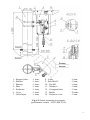
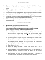
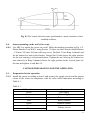
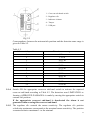
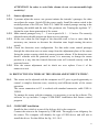
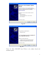
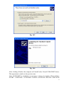
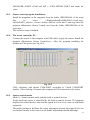
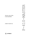
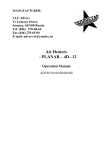
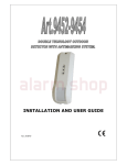
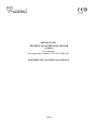
MONOSTATIC MICROWAVE INTRUSION SENSOR «FM-60» User Manual Document Part Number 4372-43071246-062 CERTIFICATE №:1120352 of 14.05.2012 2009 CONTENTS 1. 2. 3. 4. 5. 5.1. 6. 7. 8. 8.1. 8.2. 8.3. 8.4. 9. 10. 11. 12. 13. 14. 15. 16. Introduction ............................................................................................................. 3 Purpose .................................................................................................................... 3 Specifications .......................................................................................................... 3 Sensor Components ................................................................................................. 5 Sensor Structure & Operation................................ ................................................. 6 Sensor Principle of Operation ................................................................................. 6 Sensor Construction............... ................................................................................. 6 Safety Measures ...................................................................................................... 10 Mounting Procedure ................................................................................................ 10 Requirements for the sector (ground) to protect ..................................................... 10 Requirements for the room to protect ..................................................................... 11 Sensor mounting on the outside perimeter .............................................................. 11 Sensor mounting on the wall (of a room)................................................................ 12 Sensor Preparation for the Operation ...................................................................... 12 Distinctive Features of the Sensor Adjustment with PC ......................................... 15 Check of the Technical State ................................................................................... 22 Troubleshooting Guide............................................................................................ 23 Storage Conditions .................................................................................................. 24 Transportation ......................................................................................................... 24 Acceptance Certificate ............................................................................................ 24 Manufacturer’s Guarantees ..................................................................................... 24 2 1. INTRODUCTION 1.1. The present User Manual contains information on the operation of the Monostatic Microwave Intrusion Sensor «FM-60» and its performance variants «volume», «curtain», «fan» (below – the sensor) and includes the information on: − the purpose and the sensor principle of operation; − the sensor components and the possible sensor kit supply; − the sensor and its components specifications; − the operating and servicing rules. The document also contains information on the sensor tare, packaging and transportation conditions. The information represented in the present User manual is enough for the sensor correct operation, maintenance and storage. In order to continuously ensure the high standard of quality and performance of the products, the manufacturer reserves the right to modify the present technical data without notification that does not worsen the sensor specifications. 2. PURPOSE. 2.1. 2.2. 2.3. The sensor is intended to protect perimeter sites, outdoor (indoor) areas of different objects and ensures the detection of an intruder moving in his full height or bent in the detection zone. The sensor is intended for the continuous outdoor round-the-clock operation and keeps its characteristics at an ambient temperature of - 50оС … +65о С and the relative humidity up to 98% at the temperature of +35о С. The sensor distinctive feature is the detection zone consisting of 12 cross-cut subbands which can be controlled and adjusted by the controls on its enclosure or by the PC over the USB-interface (sub-bands disconnection, separate sensitivity adjustment in every sub-band, «Antimasking» function and so on). 3. SPECIFICATIONS. 3.1. The maximal range of the sensor is 60 m (12 cross-cut sub-bands 5 m each). The detection zone is a volumetric part of a sector the movement of a man in which generates an alarm. The detection zone parameters for different performance variants are given in Table 3.1. 3 Table 3.1. Parameter Width, m Height, m «FM-60-V» (volume) up to 15 up to 15 Performance variant «FM-60-C» (curtain) up to 5 up to 25 «FM-60-F» (fan) up to 25 up to 5 3.2. 3.3. The sensor ensures the range modification from 5 to 60 m. The sensor generates an alarm at: – an intruder’s crossing of the detection zone in his full height or bent at a speed of 0,3 … 8 m/sec with the probability of not less than 0,98; – the remote control signal; – the dump or reducing of supply voltage up to (4.2 + 0,4) V. An alarm is generated by breaking the individual point relay contacts for 3 sec minimum. The signal is issued with the yellow and pink marked cables. 3.3.1. At the sabotage attempts by means of the screening of the radiation with the radio reflecting or radio absorbing materials at the distance up to 2 m the signal «Antimasking» is generated 20 sec later. The signal «Antimasking» is generated by breaking the individual point relay contacts for indefinite time. In order to go back to the operating mode it is necessary to take away the masking objects and make a control passage in the nearest sensor zone. 3.4. The individual point relay parameters: maximal switching current up to 0,1 А, maximal voltage up to 50 V, resistance in the closed condition up to 130 Ohm (lightning protection elements included). 3.5. The sensor generates a tamper response at the cover unauthorized opening. The tamper response is generated by breaking the tamper contacts. The signal is issued by blue and grey coloured marked cables. Tamper operating parameters: current up to 0,2 A, voltage up to 80 V. 3.6. The recovery time of a standby mode after an alarm is 1 sec maximum. 3.7. The time of the technical availability after the supply voltage is on is 5 sec maximum. 3.8. The sensor power supply: direct voltage from 5 to 30 V and pulsation 0,03 V maximum. The sensor power is up to 0,6 W. 3.9. The sensor has the automatic and the remote control of the availability. In order to realize the remote control give the direct voltage 5 … 30 V on the green coloured cable for 1 … 3 sec. The sensor should generate an alarm. 3.10. The sensor does not generate an alarm at: the rain, snow, thick fog; the solar radiation; a wind at a speed up to 20 m/sec; 4 3.11. 3.12. 3.13. 3.14. 3.15. the movement of birds and animals (linear size up to 0,3 m) in the detection zone; the sector irregularities up to ±0,3 m; the snow cover height up to 0,3 m without the additional adjustment; the grass height up to 0,2 m; the influence of the ultra-short waves in the band of 433 MHz and a cellular phone at the distance more than 0,5 m from the sensor. The sensor is immune to EMI (voltage impulses in supply circuits, breaks of mains supply, electrostatic discharges, electromagnetic fields). The sensor input circuits are protected from the electric pickup (electric storm included). The sensor mean lifetime is 8 years. The overall dimensions of the sensor without the mounting kit (MK) are 210х135х55 mm maximum; Weight up to: 0.5 kg. 4. SENSOR COMPONENTS 4.1. 4.2. The sensor components include: transceiver unit – 1 item; mounting kit (mounting on the support): bracket – 1 item; buckle– 2 items; key S8х10 – 1 item; User Manual – 1 item; package. At the customer’s order are supplied: USB – cable for the connection to the PC; software; protective visor; mounting kit (mounting on a wall); power supply unit «PSU-U-15-0,15»; junction box «JB-15» or «JB-30». 5 5. SENSOR STRUCTURE & OPERATION 5.1. The Sensor Principle of Operation. The sensor principle of operation is based on the method of linear frequency modulation widely used in the radiolocation where the generator operating frequency is changed linearly in small limits. The super high frequency transmitter of the transceiver module radiates oscillations in the direction of the detection zone which reflect from the goal and the objects and return to the super high frequency receiver of the transceiver module. The signal changes caused by the Doppler effect at the intruder’s movement in the detection zone are intensified and treated according to the defined algorithm. If the changes top the threshold value, the sensor generates an alarm. The method of linear frequency modulation and the detection zone consisting of 12 cross-cut sub-bands allowed to increase the interference immunity and decrease false alarm rate. 6 SENSOR CONSTRUCTION. 6.1. 6.2. 6.3. The sensor appearance and its mounting on a support are given in Fig. 6.1. The sensor has a mono block construction in dust-, splash-proof enclosure. The block basic unit is Base 4. On the Base 4 there is a microstrip antenna and a signal processing unit covered with a radioparent Enclosure 5. Two bores preventing the condensate inside the block are situated in an underside of the enclosure. Remove the Cover 6 to get to the adjustment and indication controls. The sensor is connected to the control and indicating equipment using Cable 8. The cable goes through Cable Input 7 and Corrugated tube 12. The sensor transceiver unit is mounted on a support using MK-1: Bracket 2, Elastic Washer 3 and Buckles 13 according to Fig. 6.1. MK-1 provides the unit turn in horizontal plane at an angle of 3600, in vertical plane: down – not less than 150, up – not less than 400. The sensor transceiver unit is mounted in vertical plane (wall, fence, etc) using MK-2: Bracket 2, Ring 9 according to Fig. 6.2. MK-2 provides the unit turn in horizontal plane within + 650, in vertical plane: down – not less than 300, up – not less than 900. There are 3 types of Bracket 2: with the wall carry-over of 120 mm, 350 mm, 500 mm. The type of the bracket depends on the sensor application. Note – Fig. 6.1 and 6.3 represent the sensor application using the protective visor. Fig. 6.2 – without it. 6 1 – Support (tube) 2 – Bracket 3 –Bearing 4 – Base 5 – Enclosure 6 – Cover 7 – Cable Input - 1 item; - 1 item; - 1 item; - 1 item; - 1 item; - 1 item; - 1 item; 8 – Cable 9 – Bolt М6х35 10 – Nut М6 11 – Washer 6 12 – Corrugated tube 13 – Buckle 14 – Protective visor - 1 item; - 1 item; - 1 item; - 1 item; - 1 item; - 2 items; - 1 item. Fig. 6.1 Sensor mounting on a support (performance variant - curtain) 7 1 – Support (wall) 2 – Bracket 3 – Figured Elastic Washer 4 – Base 5 – Enclosure 6 – Cover 7 – Cable Input 8 – Cable - 1 item; - 1 item; - 2 items; - 1 item; - 1 item; - 1 item; - 1 item; - 1 item; 9 – Ring 10 – Nut М6 11 – Washer 6 12 – Bolt М6х16 13 – Screw 4х30 14 – Plug for the screw 15 – Corrugated tube - 1 item; - 1 item; - 2 items - 1 item; - 3 items; - 3 items; - 1 item. Fig 6.2 Sensor mounting on a wall (performance variant - curtain) 8 1 – Support (tube) 2 – Bracket 3 – Bearing 4 – Base 5 – Enclosure 6 – Cover 7 – Cable Input - 1 item; - 1 item; - 1 item; - 1 item; - 1 item; - 1 item; - 1 item; 8 – Cable 9 – Bolt М6х35 10 – Nut М6 11 – Washer 6 12 – Corrugated tube 13 – Buckle 14 – Protective visor - 1 item; - 1 item; - 1 item; - 1 item; - 1 item; - 2 items; - 1 item. Fig. 6.3 Sensor mounting on a support (performance variant – VOLUME, FAN) 9 7 SAFETY MEASURES. 7.1. 7.2. 7.3. 7.4. 7.5. 7.6. The current safety standards for the operation with electrical facilities with up to 1000 V voltage should be observed during mounting, prevention and repair of the sensor. Cables should be laid, terminated and connected to the sockets only when supply voltage is OFF. The power of the super high frequency energy beaming by the sensor meets the security standards and don’t influence on the human health. It is prohibited to mount and to maintain the sensor during lightning storm. Technicians are allowed to install, maintain and repair the system after they study special instructions and pass exam related to safety measures. Failure to comply with the exploitation requirements may lead to the untimely sensor breakdown. 8 MOUNTING PROCEDURE. 8.1. Requirements for the sector (ground) to protect. The choice of the place and the sensor correct mounting on a sector or in a room to protect are the essential factors ensuring its reliable operation. Use the protective visor when mounting the sensor outdoors. The sector (field) to protect should meet the following requirements: а) maximal height of the sector surface irregularities is +0,3m. If deflections of the sector surface from the plane exceed +0,3m; the specifications of the sensor can worsen. In this case the sensor acceptability is determined by the trial operation; b) the sector should be free of high grass, bushes and tree branches at the distance of 5 m minimum from the detection zone border; c) the detection zone and the area outside the detection zone 10 m minimum in the radiation direction should be free of huge objects and constructions vibrating fron the wind (gate wings, decrepit fences, etc); d) grass up to 0,2 m; e) snow cover up to 0,3 m; f) people and animals movement is allowed at the distance of 5 … 10 m minimum outside the detection zone; g) it is recommended to fence the sector around (fence 1 m high minimum) to avoid the accidental penetration of people and animals into the detection zone; h) when mounting the sensor on a building outside wall it is necessary to eliminate the water flow from the roof close to the sensor enclosure. 10 8.2. 8.3. 8.3.1. 8.3.2. 8.3.3. 8.3.4. 8.3.5. Requirements to the room to protect. The sensor installation in a room should meet the following requirements: a) the sensor should be installed on walls not exposed to constant vibrations; b) the room should be free of animals, birds, vibrating and moving objects (ventilation windows, doors, air exhausters, etc); c) if the sensor is installed in a room with a big square of glazing (shops, expo halls, offices, etc) the area of 3 m minimum should be free of trees and moving transport; d) the sensor should not be directed to windows and thin partitions between rooms; Sensor mounting on the outside perimeter. It is recommended to use metal or asbestos-cement tubes 70 … 90 mm diameter as supports. In case of heavy-textured soil it is allowed not to concrete the support and embed it into the ground for 600 … 800 mm. In case of light-textured soil the support should be additionally concreted for 200 mm (500 mm diameter). The height of the support over ground part should not be less than 1500 mm in case of much snow (over 1 m). In case of little snow the height of the support over ground part up to 1300 mm is sufficient. Weld on the sensor to the fence or connect it in other way for better stability in case of using the sensor to protect the top of the fence. The height of the support over the fence should not be less than 300 mm. Lay the main cables according to the project documentation. Use shielded cables as the main cables. The cables could be laid into the ground or on a fence. The mounting height is 1,0 … 1,5 m according to Fig. 6.1.. Use MK-1 to mount the sensor on a round support. Mount Bracket 2 on Support 1 using Buckles 13. Install the transceiver unit drain ports looking down on the bracket using Bolt 9. The bracket mounting should provide the sensor front face direction to the protected sector. Fix the sensor in the horizontal (relatively to the ground) plane. The detection zone model form and dimensions for the performance variant «curtain» are given in Fig.8.1. 11 Fig. 8.1 The sensor detection zone (performance variant «curtain») when installed outdoors. 8.4. Sensor mounting on the wall (of a room). 8.4.1. Use MK-2 to mount the sensor on a wall. Make the marking according to Fig. 6.2. Mount Bracket 2 on Wall 1 using Screws 13 (there are three bracket modifications – 120 mm, 350 mm, 500 mm wall carry-over). Put Bolt 12 into Ring 9 channel and fix the transceiver unit on the bracket. Loosen Nut 10 and choose the right position for the unit rotating it in horizontal plane. Tighten the nut. Moving the transceiver unit relatively to Ring 9 channel choose the right position in the vertical plane for the unit and tighten it with Bolt 12. 9. SENSOR PREPARATION FOR THE OPERATION. 9.1. Preparation for the operation. 9.1.1. Install the sensor according to item 8 and connect the supply circuit and the output circuit of the sensor in compliance with the color cables indication according to Table 9.1. Table 9.1. Cable colours White Brown Yellow Pink Green Grey Blue Purpose Plus supply Minus supply Relay contacts Relay contacts Remote control Tamper circuit 12 A model diagram of the connection of the sensor using the lightening guard unit «LGU-4» and a supply unit «PSU-U-15-0,15» is given in Fig.9.1. Tamper contacts are switched on serially with relay contacts. In this case the alarm will be generated and transmitted to a channel of the control and indicating equipment at the relay activation as well as at the tamper activation. Fig. 9.1 9.1.2. Remove Cover 6 (Fig. 6.1). When controlling the indicator «Alarm» stay behind or from a side of the sensor. 9.1.3. The required detection zone configuration is set using the 12-position microswitch. The sensitivity is modified using the regulator «Sensitivity» - «S» according to Fig. 9.2. 13 1 – Cross-cut sub-bands switch 2 – Regulator «S» 3 – Indicator «Alarm» 4 – Tamper 5 – USB port Fig. 9.2 Correspondence between the microswitch position and the detection zone range is given in Table 9.2. Table 9.2. Microswitch position 1 2 3 4 5 6 7 8 9 10 11 12 Detection zone range 0-5 m 5-10 m 10-15 m 15-20 m 20-25 m 25-30 m 30-35 m 35-40 m 40-45 m 45-50 m 50-55 m 55-60 m 9.1.4. Switch ON the appropriate cross-cut sub-band switch to activate the required cross-cut sub-band according to Table 9.2. The detection zone LIMITATION or forming «APPROVED PASSAGES» is made by moving the appropriate switch in extreme left position. If the appropriate cross-cut sub-band is deactivated the alarm is not generated when crossing this cross-cut sub-band. 9.1.5. The regulator «S» controls the sensor sensitivity. The regulator «S» position «clockwise maximum» corresponds to the maximal sensor sensitivity. The position «counterclockwise maximum» - to the minimal. 14 ATTENTION! In order to avoid false alarms do not set unreasonable high sensitivity! 9.2. Sensor adjustment. 9.2.1. 2 persons adjust the sensor: one person imitates the intruder’s passages, the other one adjusts the sensor. Switch ON the power supply. Install the micro switch in the needed position of the DZ (see Table 9.2). Make the control passage moving in the beginning, the middle and the end of the perimeter site. Turning the regulator “S”, obtain the exact alarm generation of the sensor. 9.2.2. Make control passages every 3 … 5 m at a speed of 0.1 … 1.5 m/sec. The correctly adjusted sensor should generate an alarm at every passage. 9.2.3. In the case when the real length of the detection zone is less or more than the necessary one, increase or decrease the detection zone length turning the micro switch. 9.2.4. Check the detection zone configuration. For that make some control passages through the detection zone on some range from the adjustment place of the sensor fixing the points crossing which the sensor generates alarms. If the detection zone doesn’t coincide with the protected sector, it is necessary to change the sensor position in a way that the formed detection zone will coincide exactly with the protected sector. 9.2.5. After the sensor adjustment and its check are over replace Cover 6 of the transceiver unit. 10. DISTINCTIVE FEATURES OF THE SENSOR ADJUSTMENT WITH PC. 10.1. The sensor can be adjusted with the computer too. PC gives a good opportunity to control a complex detection zone, sensitivity and different modes of the sensor operation. The sensor connection to PC is realized with standard connective cable USB AUSB B. To manage the sensor with the computer, it is necessary to set up the software. The software set up includes 2 stages: COM-PORT installation and Sensor control program. 10.2. COM-PORT installation. Install the disc (which is a part of the delivery kit) in the computer. Connect the sensor to the computer by USB cable. The supply is not obligatory for the sensor. The computer will identify the type of USB device and will ask to install the driver. For that follow the fig. 10.1-10.4. 15 Fig. 10.1 Fig. 10.2 Choose the folder COM-PORT from CD-disc in the window Search and installation options. 16 Fig. 10.3 Fig. 10.4 After clicking «Finish» the computer will install other Virtual COM-PORT driver. This operation is similar to the previous one. After COM-PORT is installed it is necessary to know its number. Please follow: START →OPTIONS →CONTROL PANEL→SYSTEM→DEVICE→DEVICES 17 MANAGER→PORT (COM and LPT) →USB SERIAL PORT and count the value. 10.3. Sensor control program installation. Install the programs on the computer from the folder «PROGRAM» of the setup disc in series: «WindowsInstaller-KB893803-v2-x86.exe», «NetFx20SP2_x86.exe». Create a folder «FM-60» on the disc C and copy there the program «Monostatic Sensor Control.exe» from the folder «PROGRAM» of the setup disc. The software setup is finished. 10.4. The sensor control by PC. Connect the sensor to the computer with USB cable, supply the sensor. Install the program «Monostatic Sensor Control.exe». After the program installing the window will be opened (see fig.10.5). Fig. 10.5 Click «Options» and choose COM-PORT according to Virtual COM-PORT number. After clicking «Connect» the computer will be connected to the sensor. 10.5. Sensor control modes Mode A – Sensor control mode with the built in control devices In this mode the sensor is controlled by the built-in control devices. The program displays the control devices state and the signal levels in every cross-cut sub bands separately. This mode permits to facilitate the sensor adjustment because the signal levels can be checked visually in the cross-cut sub bands, adjusted thresholds and range. 18 In the mode A the operating program window displays the virtual thresholds control devices, range and 12 indicators of the signal level in the cross-cut sub bands (1 – the nearest zone, 12 – the farest one). Mode B – Sensor control by PC This mode is used during the sensor adjustment to generate the complex detection zone (irregular thresholds in the sub zones, approved passages and etc.) and the «Antimasking» function activation. Attention: When using «Antimasking» function the sensor detection capability is reduced and the number of false alarms may increase. To pass in the mode B, it is necessary to choose “Control by PC” in the operating program window (see fig.10.6). Fig. 10.6 The operating window shows the signal levels in the cross-cut sub bands, 12 independent control devices in the cross-cut sub bands, the mode switch «Control Mode/ Operating Mode» and the button «Write to Memory». You can switch ON or OFF the separated cross-cut sub bands and the «Antimasking» function. The model of the bands disposition in the detection zone is given in fig.10.7. 19 Fig. 10.7 As a model we examine the sensor’s adjustment to generate the complex detection zone. It is necessary to generate the detection zone of the length 40 m and with the approved passage of the width 10 m at the distance of 15 m from the sensor. 2 persons adjust the sensor: one of them imitates the intruder’s passage; other one adjusts the sensor with PC. To generate the detection zone, transfer the sensor in the mode B – «Sensor control by PC». Transfer the switch «Control Mode/ Operating Mode» in the mode «Control Mode». The operating window will have the view given in fig.10.8. Fig. 10.8 Obtain the equal signals level with the control devices «Gain» in the cross-cut sub bands for the required detection zone doing the checking passages. In this mode the sensor generates an alarm if the signal level in the cross-cut sub bands exceeds 50 %. The optimal signal level in the cross-cut sub bands exceeds the alarm signal (50%) for 5 %. After the equal sensitivity adjustment in the cross-cut sub bands transfer the switch «Control Mode/ Operating Mode» in the mode «Operating 20 Mode». Doing the checking passages adjust the optimal thresholds with the control devices according to the required detection zone. The final stage is to specify the required detection zone and the approved passages. For that switch OFF the needless cross-cut sub bands (in our case 4, 5 and 9-12 cross-cut sub bands) with the ticks. The model of the software operating window for the required configuration is given in fig.10.9. Fig. 10.9 Doing the control passages check the detection zone too. When the checking and adjustment are over, click «Write to Memory» on the software operating field to save the configuration in the nonvolatile memory of the sensor and to switch OFF the computer. In the mode of the sensor «Control by PC» the built-in indicator «Alarm» generates the short alternating lights of the duration 0.25 sec and the interval of 4 sec. It says that it is IMPOSSIBLE to control the sensor with the built-in control devices! 21 11. CHECK OF TECHNICAL STATE 11.1. The sensor should be served by the technicians after special training and instruction. 11.2. During the service of the sensor it is necessary to conduct check and preventive works. 11.2.1. Every month carry out external examination of the sensor units and the state of the sector where Tx and Rx are installed. It is necessary to check: - the absence of dust, dirt, snow and ice on the beaming side of the transmitreceive unit and clean them if necessary; - the sector state according to the requirements of the issue 8.1. 11.2.2. Every quarter: - carry out all the works specified as works carried out every month; - check the state of the cables and cable connections; - check the reliability of the bracket adjustment. 11.2.3. During seasonal works the height of the grass and snow is checked. If the height of the grass is over 0,2 m, the grass should be cut or removed by another method. If the height of snow changes over 0,3 m, false alarms can be generated because of the signal decrease at the input of the transmit receive unit. In this case it is necessary to remove snow or to change the height of the sensor installation. After changing the height of the sensor installation, it should be adjusted according to the procedure given before. 22 12. TROUBLESHOOTING GUIDE The list of possible malfunctions and their repair is given in table 12.1. Table 12.1 Trouble 1. The receivingcontrol device constantly generates an alarm. Possible Cause 1. Disconnection in actuating relay circuit. 2. The supply voltage is absent or below the norm. 3. The protected area doesn’t meet the necessary requirements. 2. False alarms. 4. The transmitterreceiver unit is out of order. 1. Moving objects in the detection zone. 2. Animals movement in the sector. 3. Too high sensitivity. 3. The sensor does not generate alarms when an intruder crosses the detection zone. 1. Too low sensitivity. 2. The transmitterreceiver unit is out of order. Repair Check the cable integrity and the accuracy of its connection. Provide the necessary supply voltage of the sensor. Inspect the protected area according to the requirements of the issue 8 and remove the defects. Replace the transmitterreceiver unit. Inspect the remove factors. sector and interference Align the sensor according to the issue 9. Align the sensor according to the issue 9. Replace the transmitterreceiver unit. 23 13. STORAGE 13.1. The sensor should be stored in the package for the transportation and correspond to the storage conditions of cold storage. During storage the influence of hostile environment should be prevented. 14. TRANSPORTATION 14.1. Packaged sensors can be transported by any transport (if by plane – in pressurized modules) if they are transported in covered cars, holds or covered bodies, they can be transported at the distance up to 10 000 km. The boxes should be placed to prevent their shifting or fall in case of jolts and blows. 15. ACCEPTANCE CERTIFICATE The Monostatic Microwave Intrusion Sensor «FM-60-__», №_______________ meets performance specifications of the Document Part Number 4372-43071246062 and it is considered as operable. Date of issue _________20___. Quality department 16. MANUFACTURER’S GUARANTEES 16.1. 16.2. 16.3. 16.4. The manufacturer guarantees the conformity of the sensor specifications to the Document Part Number requirements 4372-43071246-062 if a user meets the service conditions and operating rules specified by the Document Part Number 4372-43071246-062. Warranty period is 3 years since the date of sale by the manufacturer. Warranty does not cover sensors: with broken guarantee stamps; with mechanical failures, and also those which are out of order because of natural disasters (lightning, fire and flood). Mean lifetime is 8 years. 24