1
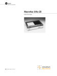
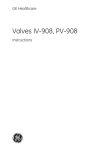
Appendixbok 11003486AA.book Page 1 Wednesday, April 27, 2005 2:58 PM
GE Healthcare
Monitor UVis-920
Appendix to User Manual, BioProcess system control
Appendixbok 11003486AA.book Page 2 Wednesday, April 27, 2005 2:58 PM
Appendixbok 11003486AA.book Page 3 Wednesday, April 27, 2005 3:00 PM
1
Appendix
1
Appendix
1.1
Monitor UVis-920, BioProcess system control
Monitor UVis-920 is a UV and visible light absorption monitor for use in liquid
chromatography. The instrument is designed as a stand-alone instrument but
can as option be equipped with a process card and an extended rear panel for
use in a BioProcess™ system.
The process card offers possibilities to control UVis-920 with digital signals or an
external display box, and receive UV absorbance data on a 4-20 mA output.
The User Manual 11-0031-12 is valid also for the BioProcess system control
version of the UVis-920. This appendix gives additional information only.
1.2
Connecting electrical cables
The sockets for electrical signals are located on the rear panel.
Display
Display
Digital input
Analog
out
0-1 V
Voltage
Frequency
Power max
100 - 240 V
50 - 60 Hz
35 VA
Digital
input
Digital output
Service
0
I
Digital
output
Current loop 4-20 mA
Remote
4 - 20 mA
Fig 1-1. UVis-920 rear panel for use in a BioProcess system
Appendix 11-0034-86 AA to UVis-920 User Manual
3
Appendixbok 11003486AA.book Page 4 Wednesday, April 27, 2005 3:00 PM
1
Appendix
1.2.1
Connecting digital input signals
Connect digital input signals to the 9-pole D–Sub male Digital input connector.
All digital inputs are galvanic isolated from UVis-920 main electronic. All inputs
uses TTL-levels by default. With jumper W1 on the process card the alter level can
be changed to 10 volt.
9
8
7
6
5
4
3
2
1
Pin
Signal
Function
1
Set range bit 0
Set AU-range for 4-20 mA output
2
Set range bit 1
3
Set range bit 2
4
Set range bit 3
5
Auto zero
0=autozero
6
Run/End
0=run, 1=end
7
Keyboard lock
0=display locked
1=display works normally
8
Voltage 5 or 12 V
(max 100 mA)
Output voltage for external pull-ups
9
Ground 0 V
Table 1-1.
4
Appendix 11-0034-86 AA to UVis-920 User Manual
Appendixbok 11003486AA.book Page 5 Wednesday, April 27, 2005 3:00 PM
1
Appendix
1.2.2
Connecting digital output signals
All digital outputs are placed in the 15-pole D–Sub female Digital output
connector and functions as a relay that closes to ground. Hence external pull-ups
are needed. All digital outputs are galvanic isolated from UVis-920 main
electronic.
15
14
10
9
8
7
3
2
1
Pin
Signal
Function
1
Get range bit 0
Shows AU-range for 4-20 mA
2
Get range bit 1
3
Get range bit 2
4
Get range bit 3
5
Filter code bit 0
6
Filter code bit 1
7
Filter code bit 2
8
Filter code bit 3
9
Error code on display
0=error, 1=no error
10
Run end
0=running, 1=end state
11
Out of range
0=AU-value is out of range
Shows code for inserted filter
1=AU-value is in range
12
Ground 0 V
13
14
24 V max 100 mA
Output voltage for external pull-ups
15
Table 1-2.
Appendix 11-0034-86 AA to UVis-920 User Manual
5
Appendixbok 11003486AA.book Page 6 Wednesday, April 27, 2005 3:00 PM
1
Appendix
1.2.3
Binary range codes for digital inputs and outputs
Binary value range code
Range
Bit 3
Bit 2
Bit 1
Bit 0
0
0
0
0
Not used (when this value is set on digital
input, range can be changed from display)
0
0
0
1
(-1 6)
AU
0
0
1
0
(-0.5 3)
AU
0
0
1
1
(-0.25 1.5)
AU
0
1
0
0
(-0.125 0.75) AU
0
1
0
1
(-1 1)
AU
0
1
1
0
(0 1)
AU
1
1
1
1
Not used (when this value is set on digital
input, range can be changed from display)
Table 1-3. Binary range codes for digital inputs and outputs
1.2.4
Binary filter codes for digital outputs
Binary filter code
Filter wavelength
Bit 3
Bit 2
Bit 1
Bit 0
0
0
0
0
Filter not fitted
1
0
0
1
546 nm
1
0
1
0
405 nm
1
0
1
1
280 nm
1
1
0
0
260 nm
1
1
0
1
215 nm
1
1
1
0
Custom filter
1
1
1
1
No filter inserted
Table 1-4. Binary filter codes for digital outputs
6
Appendix 11-0034-86 AA to UVis-920 User Manual
Appendixbok 11003486AA.book Page 7 Wednesday, April 27, 2005 3:00 PM
1
Appendix
1.2.5
Connecting equipment to 4-20 mA output
Connect any equipment to the 3-pole female connector Current loop
4-20 mA.
3
2
1
Ground
+
Output
current
Pin
Signal
Function
1
+
Output current
2
-
Output current
3
GRD
Ground
Table 1-5.
1.3
Error messages
Error codes 201-206 are internal errors that the BioProcess interface shows on
its display.
Message
Description/Action
Error 201
Not connected
BioProcess interface has no connection to UVis920. Call GE Healthcare.
Error 202
Internal error
Internal error. Call GE Healthcare.
Error 203
Communication
Communication protocol between BioProcess and
UVis-920 differ. Call GE Healthcare.
Error 204
Communication
BioProcess interface has no connection to UVis920. Call GE Healthcare.
Error 205
Communication
BioProcess could not connect to UVis-920 at startup. Call GE Healthcare.
Error 206
Serial no not valid
Flow Cell serial number entered from the
BioProcess display is not valid
Table 1-6.
Appendix 11-0034-86 AA to UVis-920 User Manual
7
Appendixbok 11003486AA.book Page 8 Wednesday, April 27, 2005 3:00 PM
1
Appendix
1.4
Run
Press OK to End_
End
Press OK to Run_
280nm
0.4567342AU
Menu overview, BioProcess system control
14%
Note. Displays with darker shading are unique for BioProcess system control.
280nm
CL=1.00mm
0.4567342AU
Autozero
Set 4-20 mA Range
-1 6>
Setup
Set Averaging Time
(2.56s)
<2.56>
Set 4-20 mA Range
(-1 6)
Set Averaging Time
Set Cell Serial Number
Set Cell Type
Set Cell Path Length
(2.00mm)
Reset Filter Time
Set Cell Serial Number
(123456)
<123456>
Set Cell Serial Number
(123456)
123456
The serial number must be 1000 or higher.
Set Cell Type
(2mm)
<2.00>
Set Cell Path Length
(2.00mm)
2.00
Set Wave Length
(351nm)
Set Wave Length
(351nm)
387
Reset Filter Time
Set Unit Number
(0)
Set Display Contrast
yes no
Set Unit Number
(0)
0
Set Display Contrast
5
Check
OK Menu or selection accepted
Esc Moves back one menu level or
cancel a value
Autozero
Light Intensity
Filter Used Time
Lamp UsedTime
Flow Cell
8
2 Open values within range
<2> Preset values
_ New value to be set (underscore)
4-20 mA
6.28 mA
4-20 mA
Open circuit
Check 4-20 mA
Check 4-20 mA
Testing
Software Version
Main
Process
Press Esc to leave this display.
V1.00.00
V1.00.00
Appendix 11-0034-86 AA to UVis-920 User Manual
Appendixbok 11003486AA.book Page 9 Wednesday, April 27, 2005 3:00 PM
1
Appendix
1.5
Menus
Most of the windows (messages) that the BioProcess interface shows on its
display are identical with the windows presented on the stand alone UVis-920
display, except the one marked with darker shading in the menu overview. These
are unique for the BioProcess system control interface. See 1.4 Menu overview,
BioProcess system control.
1.5.1
Main menu
To start and stop the monitor (compare with the run/end key on the monitor):
1 Start measuring (run mode), press OK.
End
Press OK to Run_
Run
Press OK to End_
280nm
0.4567342AU
2 Stop measuring (end mode), press OK.
The display shows the filter wavelength in nm and the absorbance value in AU.
14% The percentage of the set 4-20 mA range that the absorbance value corresponds
to is also indicated.
Example: If 4-20 mA is set to (0 1) and the absorbance value is 0.5 AU, the display
shows 50%.
280nm
CL=1.00mm
0.4567342AU
Indicates the filter wavelength in nm, cell path length in mm and the current AU
value.
Autozero
The autozero display/function sets the detected absorbance to zero when OK is
pressed.
1.5.2
Setup menu
Set 4-20 mA range
This menu allows you to select range for the 4-20 mA output.
1 Select menu Setup and press OK.
2 Select menu Set 4-20 mA Range, press OK.
Set 4-20 mA Range
(-1 6)
3 Set the range in AU, press OK.
Set 4-20 mA Range
-1 6>
Value
Range
-1 6
-1 to +6.0 AU
-0.5 3
-0.5 to + 3.0 AU
-0.25 1.5
-0.25 to +1.5 AU
-0.125 0.75
-0.125 to +0.75 AU
-1 1
-1.0 to +1.0 AU
01
0 to +1.0 AU
Appendix 11-0034-86 AA to UVis-920 User Manual
9
Appendixbok 11003486AA.book Page 10 Wednesday, April 27, 2005 3:00 PM
1
Appendix
Set unit number
The unit number for UVis-920 can be selected by the user.
1 Select menu Setup and press OK.
2 Select menu Set Unit Number, press OK.
Set Unit Number
(0)
Set Unit Number
(0)
3 Set unit number, press OK. Values: 0-9.
<9>
Set display contrast
The display contrast can be selected by the user.
1 Select menu Setup, press OK.
Set Display Contrast
2 Select menu Set Display Contrast, press OK.
3 Set contrast, press OK. Values: 0-9.
Set Display Contrast
5
1.5.3
Check menu
Indication of 4-20 mA output
The current value of the 4-20 mA output can be indicated.
1 Select menu Check, press OK.
4-20 mA
6.28 mA
4-20 mA
Open circuit
2 Select sub menu 4-20 mA, press OK. The display shows the current value in
mA.
If the 4-20 mA output is not used (not connected) the display shows Open circuit.
Check 4-20 mA output
The function of the 4-20 mA output can be tested.
1 Select menu Check, press OK.
Check 4-20 mA
Check 4-20 mA
Testing
2 Select sub menu Check 4-20 mA, press OK.
3 Start the test, press OK. The test will ramp the
output up to 20 mA and then decrease the
signal in 10% steps back to 4 mA. The test is
run continuously.
20 mA
4 mA
Stop the test by pressing Esc.
10
Appendix 11-0034-86 AA to UVis-920 User Manual
Appendixbok 11003486AA.book Page 11 Wednesday, April 27, 2005 3:00 PM
1
Appendix
Software version
1 Select menu Check, press OK.
Main
Process
V1.00.00
V1.00.00
2 Select menu Software Version, press OK. The display shows the software
version of the main system and the process system.
Appendix 11-0034-86 AA to UVis-920 User Manual
11
Appendixbok 11003486AA.book Page 12 Wednesday, April 27, 2005 3:00 PM
1
Appendix
12
Appendix 11-0034-86 AA to UVis-920 User Manual
Appendixbok 11003486AA.book Page 13 Wednesday, April 27, 2005 2:58 PM
Appendixbok 11003486AA.book Page 14 Wednesday, April 27, 2005 2:58 PM
www.chromatography.amershambiosciences.com
Drop Design and BioProcess are trademarks of GE Healthcare Ltd.
GE and GE monogram are trademarks of General Electric Company.
GE Healthcare
Amersham Biosciences AB
Björkgatan 30
751 84 Uppsala
Sweden
All goods and services are sold subject to the terms and conditions of sale of
the company within GE Healthcare which supplies them. GE Healthcare
reserves the right, subject to any regulatory and contractual approval, if
required, to make changes in specifications and features shown herein, or
discontinue the product described at any time without notice or obligation.
Contact your local GE Healthcare representative for the most current
information.
© 2005 General Electric Company – All rights reserved.
Amersham Biosciences AB, a General Electric company going to market as GE
Healthcare.
GE Healthcare Amersham Biosciences AB
Björkgatan 30, 751 84 Uppsala, Sweden
GE Healthcare Amersham Biosciences Europe GmbH
Munzinger Strasse 9, D-79111 Freiburg, Germany
GE Healthcare Amersham Biosciences UK Ltd
Amersham Place, Little Chalfont, Buckinghamshire, HP7 9NA, UK
GE Healthcare Amersham Biosciences Corp
800 Centennial Avenue, P.O. Box 1327, Piscataway, NJ 08855-1327, USA
GE Healthcare Amersham Biosciences KK
Sanken Bldg. 3-25-1, Hyakunincho, Shinjuku-ku, Tokyo 169-0073, Japan
imagination at work
Appendix 11-0034-86 AA
ProTang Teknikinformation 2005
Asia Pacific Tel: +852 2811 8693 Fax: +852 2811 5251 • Australasia Tel: + 61 2 9899 0999 Fax: +61 2 9899 7511 • Austria Tel: 01/57606-1619 Fax: 01/57606-1627 • Belgium Tel: 0800 73 888
Fax: 03 272 1637 • Canada Tel: 800 463 5800 Fax: 800 567 1008 • Central, East, & South East Europe Tel: +43 1 982 3826 Fax: +43 1 985 8327 • Denmark Tel: 45 16 2400 Fax: 45 16 2424 • Finland &
Baltics Tel: +358-(0)9-512 39 40 Fax: +358 (0)9 512 39 439 • France Tel: 01 69 35 67 00 Fax: 01 69 41 96 77 • Germany Tel: 0761/4903-490 Fax: 0761/4903-405 • Italy Tel: 02 27322 1 Fax: 02 27302 212
• Japan Tel: +81 3 5331 9336 Fax: +81 3 5331 9370 • Latin America Tel: +55 11 3933 7300 Fax: +55 11 3933 7304 • Middle East & Africa Tel: +30 210 9600 687 Fax: +30 210 9600 693 • Netherlands
Tel: 0165 580 410 Fax: 0165 580 401 • Norway Tel: 815 65 555 Fax: 815 65 666 • Portugal Tel: 21 417 7035 Fax: 21 417 3184 • Russia & other C.I.S. & N.I.S Tel: +7 (095) 232 0250, 956 1137 Fax: +7 (095)
230 6377 • South East Asia Tel: 60 3 8024 2080 Fax: 60 3 8024 2090 • Spain Tel: 93 594 49 50 Fax: 93 594 49 55 • Sweden Tel: 018 612 1900 Fax: 018 612 1910 • Switzerland Tel: 0848 8028 12 Fax:
0848 8028 13 • UK Tel: 0800 616928 Fax: 0800 616927 • USA Tel: 800 526 3593 Fax: 877 295 8102