Transcript
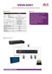
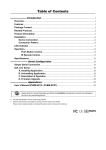
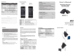
Specifications
Cabling Requirements
Transmitter Unit
Receiver Unit
EVBMN-110L
EVBMN-110R
Input → Output
HDMI → RJ-45
RJ-45 → HDMI
Status LED
Dual Color x 1
Dual Color x 1
LED
LAN LED
Single Color x 3
Single Color x 3
Video Resolution (max.)
Full HD (1080p@60Hz)
Extension Distance
100M
RJ-45 x 3
RJ-45 x 3
Ethernet Port
10/100 Mbps
DCE, DB9-F
DTE, DB9-M
Serial Port
115kbps (max.)
x 1, IR Transceiver x 1, IR Transceiver
IR Extension
x 1, IR Receiver
x 1, IR Receiver
Power Supply
DC 12V (Phantom Power)
Enclosure
Metal
Weight (gram)
410~420
H x W x D (mm)
140 x 85 x 34
HDMI transmission running along the Ethernet cabling is particularly
susceptible to EMI (electro magnetic interference) or RFI (radio frequency
interference). It can be caused by being in close to fluorescent lighting or
power cabling. The following are some considerations that you should pay
attention to.
EVBMN-M110
*Above video resolution and extension distance are based on a single CAT5e/6
24AWG solid cable without cascade. STP cabling is recommended for environments
with high EMI or RFI. For the best performance results, using stranded cabling or
other thinner cables, and coiling of excess cable lengths should be avoided.
Limited Warranty
IN NO EVENT SHALL THE DIRECT VENDOR'S LIABILITY FOR DIRECT OR INDIRECT,
SPECIAL, INCIDENTIAL OR CONSEQUENTIAL DAMAGES, LOSS OF PROFIT, LOSS
OF BUSINESS, OR FINANCIAL LOSS WHICH MAY BE CAUSED BY THE USE OF THE
PRODUCT EXCEEDS THE PRICE PAID FOR THE PRODUCT.
The direct vendor makes no warranty or representation, expressed or implied with respect to
the contents or use of this documentation, and especially disclaims its quality, performance,
merchantability, or fitness for any particular purpose.
1. Place cables away from fluorescent lights, air conditioners, and machines
that are likely to generate electrical noise.
2. The shielded cables (FTP, STP) are suggested for they can reduce the
interference, and work better to EMI or RFI than UTP cables.
3. For superior video quality, unbundled cables work better than bundled
ones. Bundled cable of greater than 3 ft. diameter will have minor effect on
the cable length.
4. The solid cable will work better than stranded cable. It may shorten the
transmission distance if you use stranded cabling or other cables thinner
than 24AWG. That is, solid cable of larger than 24AWG is strongly
suggested. Additionally, CAT6 is more recommended.
5. Joined cables can result in signal loss and shortening transmission
distance. Therefore, for the optimal transmission distance, we recommend
using only one piece of cable (without any immediate joints) between
transmitter and receiver units.
Other Notices
1. Due to EMI or RFI, some certain brands/types of displays, like monitors
and TVs, may result fuzzy or snowing on screens. In this case, please try
to restart the displays.
2. As the system transmits massive data, temperature rises on the unit is a
normal phenomenon, so please do not open any components inside by
yourself.
3. The unit is a sealed structure; should not be tampered with by anyone
other than registered installer.
All the brand names and registered trademarks are the property of their respective owners.
Connection Pattern
● Prior to installation, ensure to power off all devices that will be
connected to this system.
● Ensure that all devices you will connect are properly grounded.
● Place cables away from fluorescent lights, air conditioners, and
machines that are likely to generate electrical noise.
Users can connect the video source to the Transmitter Unit, connect
the monitor to the Receiver Unit. Connect to Ethernet devices to the
Transmitter and the Receiver Units (LAN ports) and use CAT5e/6 cable
(EIA / TIA 568B industry standard compliant) for the connection between
the Transmitter (Link Port) and Receiver Unit (Link Port) . After all device
connections are completed, connect the provided power cord into an
appropriate power source and plug the opposite end into the power
connector* on the Unit to power up.
Serial Devices
IR Receiver
EVBMN-M110
(EVBMN-110L + EVBMN-110R)
Package Contents
● Transmitter Unit
● Receiver Unit
● Power Adapter Set
Power Adapter with necessary AC Cord
or
Plug-in Power Adapter
● User’s Manual
● Foot Pad Set
● IR External Sensor Kit
● CAT5 Cable
● Grounding Wire
x1
x1
x1
Related Products (without Ethernet & Serial function)
Type
100M
Tx + Rx EVBM-M110
Tx
EVBM-1104L
(Splitter)
Rextron
PP5-HEM152Z-000
RoHS
Front Panel
La
LAN LED
Yellow: LAN status (Data communication)
Ls
Status LED
[Tx] Blue: Link status; Green: Power on;
Flashing Blue+Green: Power-saving mode
[Rx] Blue: Link status; Red: Power on;
Flashing Blue+Red: Power-saving mode
T1 R1
RJ-45
Connector
Connect to Ethernet devices
T2 R2
HDMI
Connector
[T2] Connect to an HDMI video source
[R2] Connect to an HDMI disply
T3 R3
RJ-45
Connector
Use CAT5e/6 for connection between two units.
Rx
La
CAT5 100M
Ls
Rear Panel
ADSL
P
IR2(out) IR1(in)
T4
Tx
Grounding T3
IR Receiver
EVBM-1074L
Function
CAT5 HDMI Extender Pair
CAT5 HDMI Splitter (2-in / 4-out)
with Auto-sensing function
◘ The final specification is the actual product based.
◘ Features and functions may be added or changed
after the manual was written. Please visit our
website to download the latest version of manual
for reference.
Tx / Rx
IR Transceiver
70M
EVBM-M107
Tx
CAT5 HDMI Switch-Splitter (4-in / 4-out)
(Switch- EVBM-S1504L EVBM-S1474L
with Auto-sensing function
Splitter)
x1
x2
x1
x1
x2
IR Transceiver
Operation
1. The system will disable the video output signal when it detects nonHDCP compliant display(s) on playing the HDCP video source. All the
connected output displays MUST be HDCP compliant, when the video
source is HDCP compliant.
2. If there’s no signal detected from HDMI port, the baud rate will
automatically speed down to 9,600 bps.
HDMI Extender over CAT5
with IR, Ethernet & Serial Extending
Product Description
CAUTION: The CAT5e/6 cables that connect the Transmitter and Receiver
Units carry electrical current and should not be plugged in to other
devices, as they may cause damage. We strongly recommend marking the
CAT5e/6 cables you are using with this product at both locations for easy
identification.
The LEDs on the Extender Units show the real-time status indicating the
linking and communication between the Transmitter Unit and Receiver
Unit. Users can identify the present status through the LED indicator on
the top.
The quality of the output signal will depend largely upon the quality of
video source, cable and display device used. Low quality cables degrade
output signal causing elevated noise levels. Please use the proper cable
and make sure the display device is capable of handling the resolution
and refresh rate selected.
NOTE:
● Send HDMI signal to multimedia display over CAT5e/6 cable of up to
100 meters
● Transmit full uncompressed HD video and audio over cable
● 100BaseT Ethernet Pass-Thru; simultaneously distribute HDMI and
Ethernet streaming video from source to display
● Low cost standard CAT5e/6 LAN cable; advanced and inexpensive
all-in-one connectivity technology
● HDCP compliant and Blu-ray ready
● Support Deep Color, HD-3D video and HD Audio formats
● Support resolution up to Full HD 1080p / 2048 x 1152
● Bi-directional LAN & Serial & two-way IR control
● IR extension supported
● Support Phantom Power -- single power supply at either one end of
two units (Tx & Rx)
● Compact size; easy to set up; simple to install
● Ideal for hospitality (hotels, conference rooms), digital signage
(airports, shopping malls), surveillance cameras, whole-home
networking and point-to-point consumer applications
Optional:
● IR External Sensor Kit
● HDMI Cable
● Serial Cable
The direct vendor also reserves the right to revise or update the product or documentation
without obligation to notify any user of such revisions or updates. For further information,
please contact your direct vendor.
Installation
User's Manual
Features
T2
T1
T4 R4 Serial Port
[T4] (DCE) Connect to a computer
[R4] (DTE) Connect to a serial device
IR1(in)
Connect to an IR Receiver
IR1(out) IR Remote
IR2(in) Jack
Connect to an IR Transceiver
IR2(out)
Connect to an IR Transceiver
P
To Serial Terminal
P
IR2(in)
IR1(out)
Rx
Grounding
Switch Hub
R3
R2
R1
Power Supply* Apply power to the unit.
*Phantom Power: Only one power adapter is required to power the entire
system. The power adapter may be connected to either the Transmitter Unit
or the Receiver Unit.
R4
Tx
Connect to an IR Receiver