Transcript
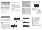
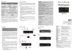
Specifications
Local Unit
Input
Output
Top
Video OK LED
Panel
Link OK/ Power LED
LEDs
Learn Audio Config Button
3D-video Supported
Remote Unit
HDMI x 1
HDMI x 1
x1
1.The OM3 Multi-Mode untwisted-pair fiber optics cable (50/125 and
62.5/125) terminated with SC duplex connectors is recommended to
use for the interconnection between Local Unit and Remote Unit. The
table below shows the specifications.
N/A
HDMI x 2
x1
x1
x1
x1
N/A
Cable
Diameter
(micron)
Yes
Full HD (1920 x 1080)
WUXGA (1920 x 1200)
800M (1080p)
1600M (1080i)
Fiber Optics
3 W (each Unit)
435
430
24 x 75 x 150 (each Unit)
Max. Video Resolution
Extension Distance
Connection
Power Consumption (Max.)
Weight (g)
H x W x D (mm)
The direct vendor makes no warranty or representation, expressed or implied with respect to
the contents or use of this documentation, and especially disclaims its quality, performance,
merchantability, or fitness for any particular purpose.
The direct vendor also reserves the right to revise or update the product or documentation without
obligation to notify any user of such revisions or updates. For further information, please contact
your direct vendor.
All the brand names and registered trademarks are the property of their respective owners.
IR Transceiver IR Receiver
L1
2
L2 L3
L4
R1
Remote Unit
R6 R7
Le L6 L7
L1 R1 SC-SC Fiber Interface
L2
HDMI Connector
R2 HDMI Connector
L3 R3 Power Supply
L4 R4 Video OK LED
Link OK /
L5 R5
Power LED
L6 R6 HDMI Connector
L7 R7 IR Control Jack
Learn Audio Config
Button
Connect the Multi-Mode optical fiber to this port
Connect to the HDMI source
Connect to the HDMI monitor
Apply the proper power to the unit
Yellow: Video Signal OK / EDID Configuration
Green: Power On
Blue : Connect to a powered-on extender unit
Connect to the HDMI monitor
Plug the external sensor here
(L7:Transceiver / R7:Receiver)
EDID Configuration
1080i
1080p
1080i
1080p
Max. Cable
Length
(meter)
1000
1000
350
350
Installation
Operation
The LEDs on the Extender Units show the real-time status indicating the
linking and communication between the Local Unit and Remote Unit. Users
can identify the present status through the LED indicator on the top.
The quality of the output signal will depend largely upon the quality of video
source, cable and display device used. Low quality cables degrade output
signal causing elevated noise levels. Please use the proper cable and make
sure the display device is capable of handling the resolution and refresh rate
selected.
R5
Local Unit
Video Signal
Users can connect the video source to the Local Unit, connect the monitor to
the Local Unit and/or Remote Unit, and use a SC to SC duplex multi-mode
fiber optics cable for the SC-SC fiber port connection between the Local and
Remote Unit. After all device connections are completed, connect the provided
power cord into an appropriate power source and plug the opposite end into
the power connector on the Unit to power up.
3
R4
L5
Le
R2 R3
62.5/125μM
Before Installation
● Determine where the Local and Remote Unit will be located
● Use SC to SC duplex Multi-Mode fiber optics cable (50/125 or
62.5/125) for the interconnection between Local and Remote Unit
● Make sure that the Fiber cable length is long enough for the
connection between the Local Unit and the Remote Unit to prevent
having to splice fiber. Try to complete the installation in one pull
● Never attempt to disassemble or reassemble the enclosure for any
purpose. This may cause personal injury and/or property damage.
(optional)
Product Description
50/125μM
2.Users may need to order appropriate cable lengths conforming to the
application environment; however, the maximum cable length should
not exceed 1,600 meters; otherwise, the signal degradation may occur
especially for video resolution.
3.Do not exceed the cable bend radius. Fiber optic cable can be broken
when kinked or bent too tightly, especially during pulling.
4.Do not twist the cable. Twisting the cable can stress the fibers.
Tension on the cable and pulling ropes can cause twisting.
5.Don’t look into the ends of any fiber optic cables. Exposure to invisible
laser radiation may result.
6.Follow the cable manufacturer's recommendations. Fiber optic cable
is often custom designed for the installation and the manufacturer
may have specific instructions on its installation.
Limited Warranty
IN NO EVENT SHALL THE DIRECT VENDOR'S LIABILITY FOR DIRECT OR INDIRECT,
SPECIAL, INCIDENTIAL OR CONSEQUENTIAL DAMAGES, LOSS OF PROFIT, LOSS OF
BUSINESS, OR FINANCIAL LOSS WHICH MAY BE CAUSED BY THE USE OF THE PRODUCT
EXCEEDS THE PRICE PAID FOR THE PRODUCT.
1
!
Duplex Multi-Mode Optical Fiber Installation
NOTE:
1. The system will disable the video output signal when it detects nonHDCP compliant display(s) on playing the HDCP video source. All the
connected output displays MUST be HDCP compliant, when the video
source is HDCP compliant.
2. 2D monitor might disable the video output signal when it detects 3D
video source. All the connected output displays MUST be 3D
compliant, when the video source is 3D-video .
EDID Configuration (Local Unit only)
In some cases display problems may occur due to incorrect EDID
communication between the display monitor and the unit or inappropriate
EDID data programmed by display manufactures. By pressing Learn Audio
Config button on the top panel of local unit, it enables to learn EDID from EDID
compliant monitors or has the system automatically optimized all valid (Audio
and/or Video) outputs for minimum requirement. The following diagram is the
summary of EDID Configuration.
User's Manual
Caution
Do not stare into beam or view directly into the ends of any
fiber optic cables. Exposure to invisible laser radiation may
result. The laser beam can cause injury to the eye.
HDMI Extender over Fiber
Features
● Extend the Video Signal up to 1600~2000M @ 1080i /
800~1000M @ 1080p
far away via Fiber Optics Multi-Mode technology
● Pure digital transmission with Zero Compression
● EDID Learning function increases display capability
● IR extending function available
● Compliant with HDMI 1.3b specification
● 3D-video, HDCP compliant and Blu-ray ready
● No any software and driver installation required
Package Contents
HDMI Extender Local Unit
HDMI Extender Remote Unit
Power Adapter Set
Power Adapter with necessary AC Cord
or
Plug-in Power Adapter
or
USB Power Cable
User’s Manual
Multi-Mode SC-SC duplex Fiber Optic Cable (for test)
Foot Pad Set
Optional: IR External Sensor Kit
x1
x1
x2
x1
x1
x2
x1
System Requirements
1. HDCP compliant Monitors with HDMI interface for the HDCP video
source
2. HDMI Cable
◘ The final specification is the actual product based.
◘ Features and functions may be added or changed
after the manual was written. Please visit our
website to download the latest version of manual
for reference.
RoHS
PP5-F3AM57Z-001
Mode 1: Auto Mixing + EDID Learning
Step 1. Press Learn Audio Config Button for 3 seconds.
Step 2. Release the button right after the Video OK LED flashes yellow quickly.
Step 3. Next, when it flashes yellow twice, it indicates learn successfully
and the system will reboot.
(Otherwise, if it flashes 4 times, it signifies failed learning. Please try again.)
LED Indicator
Press Learn Audio
Config Button for…
Now the system enters Auto Mixing & Learn Local Monitor Audio EDID
mode. Therefore, it will copy local monitor (Audio) EDID and the system
automatically optimizes all valid (Video) outputs for minimum requirement and
all connected monitors use learned (Audio) EDID of the local monitor.
Mode 2: EDID Learning
Step 1. Press Learn Audio Config Button for 6 seconds.
Step 2. Release the button right after the Video OK LED Indicator flashes
yellow slowly.
Step 3. Next, when it flashes yellow twice, it indicates learn successfully
and the system will reboot.
(Otherwise, if it flashes 4 times, it signifies failed learning. Please try again.)
Now the system enters Learn Local Monitor EDID mode. Thus, it will learn
local monitor (Audio + Video) EDID and all connected monitors use learned
(Audio + Video) EDID of the local monitor.
Mode 3: Auto Mixing
Step 1. Press Learn Audio Config Button for 9 seconds.
Step 2. Release right after the Video OK LED Indicator goes off.
Step 3. Next, when it flashes yellow twice, it indicates learn successfully
and the system will reboot.
(Otherwise, if it flashes 4 times, it signifies failed learning. Please try again.)
Now the system enters Auto Mixing mode. In this way, the system
automatically optimizes all valid outputs (Audio + Video) for minimum
requirement.
Video OK
LED Indicator
3 seconds
Yellow: Flash quickly
6 seconds
Yellow: Flash slowly
9 seconds
Off
Status
Yellow: Flash twice
Yellow: Flash 4 times
Auto Mixing (Video) &
Copy local monitor EDID
(Audio)
Copy Local Monitor
EDID (Video + Audio)
Auto Mixing
(Video + Audio)
Successful copy &
System reboot
Failed copy
EDID Configuration
Mode
EDID
Video EDID
Auto Mixing : Min. (of all)
Auto Mixing & Automatically optimize all valid
EDID Learning (Video) outputs for minimum
requirement
Learn local monitor (Video)
EDID and all connected
EDID Learning
monitors use the learned
(Video) EDID
Auto Mixing : Min. (of all)
Automatically optimize all valid
Auto Mixing
(Video) outputs for minimum
requirement
Audio EDID
Learn local monitor (Audio)
EDID and all connected
monitors use the learned
(Audio) EDID
Learn local monitor (Audio)
EDID and all connected
monitors use the learned
(Audio) EDID
Auto Mixing : Min. (of all)
Automatically optimize all valid
(Audio) outputs for minimum
requirement