1
194 Practical Variable Speed Drives and Power Electronics
If a gearbox is used, its inertia of the gearbox itself, referred to the motor,
should also be taken into consideration.
Therefore, to calculate the overall acceleration time of the drive system, the
simple formula above may be applied, provided that the acceleration torque
remains constant and the drive accelerates linearly in a uniform time.
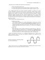
t = J Tot
2π ( n2 − n1 )
60 T A
sec
Where t = Total acceleration time in sec
JTot = Moment of inertia of the (motor + load) in kgm2
n = Final speed of the drive in rev/min
TA = Acceleration torque of the drive system in Nm
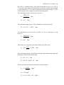
Assuming that the acceleration torque remains constant over the acceleration
period, the minimum acceleration time of the conveyor drive system is:
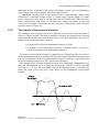
t = 1.38
2π (1430 − 0)
60
25
sec
t = 8.3 sec
This formula can be used as a rough estimate for acceleration time, but it is only an
approximation because the acceleration torque is seldom a constant value, it is the
difference in two changing values being the motor torque and the load torque.
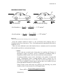
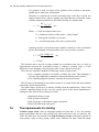
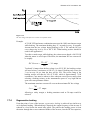
There are two alternative methods of achieving a more accurate result:
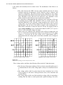
• Use a computer program to accurately calculate the result. This technique is
used by large engineering companies, motor manufacturers and vendors.
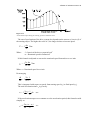
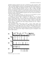
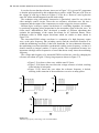
• Use a manual graphical system to calculate the acceleration time.
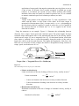
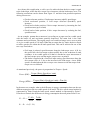
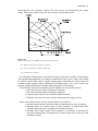
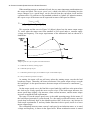
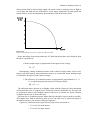
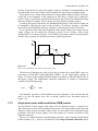
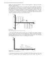
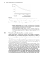
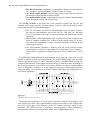
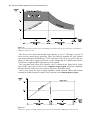
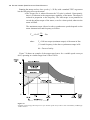
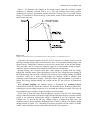
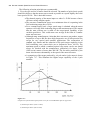
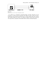
The first step in calculating the acceleration torque is to clearly define the motor and the
load torque–speed characteristics.
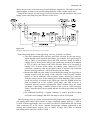
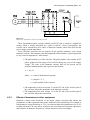
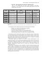
The motor torque–speed curve is usually available from the manufacturer. If this is not
available, important points on the curve are usually given in the motor manufacturer’s
catalogue in the form of the 4 points given below.
•
•
•
•
Starting breakaway torque
Pull-up torque and speed
Pull-out torque (or breakdown torque) and speed
Rated full-load torque and speed
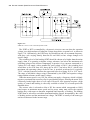
:NKXKW[OXKSKTZYLUXYZGXZOTM
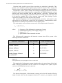
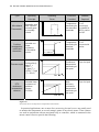
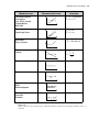
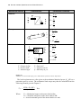
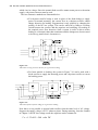
Variable torque loads, such as centrifugal pumps and fans have a very low starting
torque requirement and are easily pulled away and accelerated to the set speed by any
VSD. The main area for concern is the high breakaway torque sometimes required on
some pumps, such as slurry pumps, where some sediment can settle inside the pump