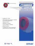
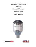
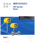
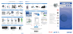
1
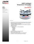
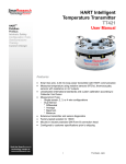
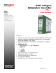
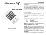
Instruction Manual ABM HART Gateway Software Instruction Manual Revision A.1 Table of Contents Section 1: Getting Started ............................................................................................................................. 3 1.1 Setup Procedure ........................................................................................................................... 3 1.2 Quick Setup Guide for Ultrasonic Sensors .................................................................................. 11 1.3 Quick Setup Guide for Radar Sensors ......................................................................................... 11 Section 2: Level Device Programming (Radar and Ultrasonic).................................................................... 12 2.1 How to Change Sensor Settings .................................................................................................. 12 2.2 Sensor ID or Polling Address ....................................................................................................... 13 2.3 Setting the 20 mA Distance to the Current Target Distance ...................................................... 14 2.4 Setting the 4 mA Distance to the Current Target Distance......................................................... 16 2.5 Entering 4/20 mA Distance Calibration Values ........................................................................... 17 2.6 Loss of Echo Alarm ...................................................................................................................... 18 2.7 Damping ...................................................................................................................................... 19 2.8 HART Programmable Settings and Tags ...................................................................................... 20 2.9 Show Sensor Calibration ............................................................................................................. 22 2.10 Profile .......................................................................................................................................... 23 Section 3: Tools Menu................................................................................................................................. 25 3.1 20mA Blanking Menu Item (Ultrasonic and Radar) .................................................................... 25 3.2 Button Menu Item (Ultrasonic and Radar) ................................................................................. 26 3.3 Using the Push Button (Ultrasonic and Radar) ........................................................................... 27 3.4 Fixed Current Mode Menu Item (Ultrasonic Only) ..................................................................... 29 3.5 Maximum Temperature Menu Item (Ultrasonic Only) ............................................................... 30 3.6 Solid/Liquid Material Menu Item (Ultrasonic Only).................................................................... 32 3.7 Units of Measure Menu Item (Ultrasonic and Radar)................................................................. 33 3.8 Self-Cleaning / Vaporized Liquids Menu Item (Ultrasonic Only) ................................................ 33 3.9 Antenna Extensions Menu Item (Radar Only) ............................................................................ 34 3.10 Low Dielectric Material Menu Item (Radar Only) ....................................................................... 34 3.11 Fixed Current (Radar) .................................................................................................................. 34 Section 4: Help Menu.................................................................................................................................. 35 Section 5 Troubleshooting .......................................................................................................................... 36 5.1 Problem: No Communication with sensor. ................................................................................. 36 5.2 Problem: Distance fluctuates. ..................................................................................................... 36 Section 6 HART Modems............................................................................................................................. 37 Smar Research Products ......................................................................................................................... 37 MACTek Corporation .............................................................................................................................. 37 2 Section 1: Getting Started This instruction manual describes the ABM HART Gateway software. HART® is a registered trademark of the HART Communication Foundation1. The ABM HART Gateway software provides a PC interface to all ABM Sensor Technology 2-wire HART enabled level sensors. Using the ABM HART Gateway users can change a sensor’s calibration and operation. 1.1 Setup Procedure The following 10 steps will assist you in setting up the Gateway software and connecting an ABM sensor. 1. Install a HART Modem Before installing the ABM HART Gateway software a HART modem must be installed. HART modems are available from Smar Research2, MACTek Corporation3 and other manufactures. See Section 6 for recommended HART modems. See your HART modem documentation for installation and setup instructions. 2. Install the ABM HART Gateway Software Install the ABM HART Gateway Software on the PC by selecting SETUP.EXE from the CD and follow the instructions on the screen. The latest software can be downloaded from www.abmsensor.com. 3. Start the ABM HART Gateway Software Click the Windows “Start” button, “Programs”, “ABM Probe Gateway” and select “HART Gateway”. 4. Select a Serial Port When the HART Gateway software is started for the first time a dialog box will appear as shown in Figure 1 (top). Click the "Next" button. Select the desired serial port from the drop down list Figure 1(middle). Figure 1 shows communication port 6 selected. Click the “Next” button. To save your selection click the "Finish" button Figure 1 (bottom). To change your selection click the "Previous" button. The selected serial port will be saved and used each time the HART Gateway software is started. After selecting a valid serial port the main screen of the ABM HART Gateway will appear as shown in Figure 2. 1 www.hartcomm.org www.smarresearch.com 3 www.mactekcorp.com 2 3 Figure 1. When the HART Gateway software is started the first time a communication wizard dialog box will appear to help select the serial port. 4 Figure 2. The main screen of the ABM HART Gateway. 5. Changing Serial Port The serial port can be changed at any time by clicking on the serial port number (see Figure 3) shown on the tank status bar. After clicking on the displayed serial port number the dialog box shown in Figure 1 will appear. Figure 3. Changing the serial port. 6. Connecting the Sensor For this step you will need a 250 ohm 1/4W (or higher) resistor (not supplied with sensor). Connect your HART modem to the sensor as shown in Figure 4. The HART modem must be connected to each side of the load resistor. (See Section 6 for HART modems we recommend.) The value of the load resistor should be 250 ohms and minimum 1/4W. Failure to use the correct value of resistor will cause communication problems and possible damage to your HART enable sensor. 5 Cable to PC Example: Smar Research HART Modem PC Adaptor HART MODEM HART modem connectors. Note: The modem cable connects to each side of the load resistor. + Input: 24 VDC - Load Resistor 250 Ohm 1/4 Watt + - ABM Sensor Figure 4. HART modem connection diagram. See sensor documentation for input voltage range. See Section 6 for HART modems we recommend. 7. Power the Sensor Connect power to the sensor. Please note: power requirements vary by device, always consult the sensor datasheet for the correct input voltage. 2-Wire Ultrasonic Level Device The loop voltage should be between 18 to 30 VDC when a 250 ohm load resister is connected (see Figure 4). 24 VDC is recommended. 2-Wire Radar Level Device The loop voltage should be between 22 to 30 VDC when a 250 ohm load resister is connected (see Figure 4). 24 VDC is recommended. 8. Start Data Link Once the sensor is powered on and the HART modem is connected to the sensor, click the ”Start Data Link” button as shown in Figure 5 to start communication with your HART enabled sensor. After clicking on the” Start Data Link” button, the button will display a green square to show the button is active. Clicking on the “Stop Data Link” button will stop communication with the sensor. Once the “Stop Data Link” button is pressed the button will display a red square to indicate that communication has stopped. 6 Figure 5. Communication with the sensor is started by clicking the “Start Data Link” button. The” Start Data Link” button will display a green square to show the button is active. 9. Loading Sensor Data The ABM HART Gateway will now attempt to communicate with the level device. If the connection is successful the Gateway software will start to download data from the sensor as illustrated in Figures 6 to 9. The Gateway software will determine the type of sensor connected and configure the toolbar buttons and menus for the sensor. The progress bar in the center of the screen shows the download progress. When the download is complete the HART Gateway is ready to use as shown in Figures 10. 7 Figure 6 ABM Gateway downloads data from the sensor and provides a description of its current operation. Figure 7. As data is downloaded from the sensor the screen will be updated with the 4mA and 20mA calibration. 8 The HART Gateway recognizes the sensor as an Ultrasonic device. Sensor readings – distance to target, loop current and level of tank. Green LED means data has been sent the sensor Green LED means the data link is good, Data is received from the sensor. Figure 8. The Gateway has determined that the connected sensor is an ultrasonic sensor. Figure 9. Once the Gateway has finished downloading the sensor data, the menus and toolbar buttons are enabled. 9 10. Ready to Use The download is complete and the progress bar in the center of the screen has disappeared, see Figure 10. The Gateway software is now ready for use. The Gateway software can be used to display calibration data or to change the sensors calibration. Before using your ABM HART enabled level device you may want to change the different programmable features to suit your application. Section 2 and Section 3 describe the different programmable features and how to use them. As a minimum you should program the 4 mA and 20 mA distances that correspond with your application. Figure 10 The HART Gateway screen after completion of the download. 10 1.2 Quick Setup Guide for Ultrasonic Sensors To setup an ultrasonic sensor you must have a HART modem installed and the ABM HART Gateway software installed as described in Section 1.1. Setup Steps 1. Connect power and the HART modem to the sensor. (Section 1.1 Step 6 and 7) 2. Start the Gateway software. (Section 1.1 Step 8) 3. Set the 4 mA and 20mA distance using the “Calib 4/20 mA” button on the toolbar. (Section 2.5) 4. Set the damping value using the “Damping” button on the toolbar. (Section 2.7) 1.3 Quick Setup Guide for Radar Sensors To setup a radar sensor you must have a HART modem installed and the ABM HART Gateway software installed as described in Section 1.1. Setup Steps 1. Connect power and the HART modem to the sensor. (Section 1.1 Step 6 and 7) 2. Start the Gateway software. (Section 1.1 Step 8) 3. Set the 4 mA and 20mA distance using the “Calib 4/20 mA” button on the toolbar. (Section 2.5) 4. Set the damping value using the “Damping” button on the toolbar. (Section 2.7) 5. Set the Low Dielectric on or off using the “Tools”, “Low Dielectric Material” menu Item. (Section 3.10) 11 Section 2: Level Device Programming (Radar and Ultrasonic) ABM HART enabled level devices can be programmed to fit your specific application. This section will describe the common functions used by both radar and ultrasonic sensors. Section 3 describes the “Tool” menus which vary depending on the device attached. 2.1 How to Change Sensor Settings The Gateway software provides dialog boxes to change each of the sensors programmable settings. When a toolbar button is clicked or a menu item is selected a dialog box will open. As shown in Figure 11 each dialog box opens and then retrieves sensor data. If the user changes the data in the dialog box and clicks the save button then each piece of data will be written to the sensor. After all data has been written to the sensor a “Sensor Updated” status will be shown before the dialog box is closed. Button or Menu Item Clicked Dialog box opens Dialog Screen PC Request data from sensor Dialog box updated with received information User changes values Cancel button clicked Save button clicked Write data to Sensor Verify data was written Yes More data to write? No Display “Sensor Updated” message Close Dialog Box Figure 11. Flow chart illustrating how all dialog boxes operate in the Gateway. If the saved button is pressed the data is written to the sensor. 12 2.2 Sensor ID or Polling Address HART enabled Sensors can be used in a multi-sensor environment where each sensor has a unique address referred to as the polling address or identification number (ID). The default polling address for all ABM sensors is 0. The polling address is displayed on the tank status bar as shown in Figure 12. To communicate with an ABM level sensor using HART, the polling address being sent by the HART Gateway must match the polling address programmed in the sensor. If the polling addresses do not match the sensor will not reply to any HART commands. To change the polling address used by the HART Gateway software click on the “Polling Address” displayed on the status bar as shown in Figure 12. To program an address in the sensor refer to the “HART Programmable Settings and Tags” in Section 2.8. Figure 12 Programming the polling address. Set the polling address to match the polling address in the sensor. By default all sensors have a polling address of 0. 13 2.3 Setting the 20 mA Distance to the Current Target Distance The 20 mA distance can be programmed to the current target distance by clicking on the “Set 20mA” button. As shown in Figure 13 the 20 mA distance calibration dialog box will appear and the Gateway will send HART commands to the sensor to retrieve the target distance. Note: This operation can be performed using the push button on the sensor, see Section 3.3 for more details. Figure 13. The 20mA distance calibration dialog. The Gateway queries the sensor to determine what the target distance is. The Gateway will continue to query the sensor until a response is received. Once a response is received from the sensor the Gateway will update the dialog box with the distance information as shown in Figure 14. 14 Figure 14. 20mA calibration dialog box showing the distance to the target. Click the “Yes” button to set the 20mA distance to the distance shown. Click the “No” button to close the dialog box without changing the calibration. 15 2.4 Setting the 4 mA Distance to the Current Target Distance The 4 mA distance can be programmed to the current target distance by clicking on the “Set 4mA” button as shown in Figure 15. Note: This operation can be performed using the push button on the sensor, see Section 3.3 for more details. Figure 15. 4mA calibration dialog box showing the distance to the target. Click the “Yes” button to set the 4mA distance to the distance shown. Click the “No” button to close the dialog box without changing the calibration. 16 2.5 Entering 4/20 mA Distance Calibration Values To manually enter the 4 and 20 mA distance click on the “Calib 4/20 mA” button. The dialog box shown in Figure 16 will appear. The desired distances can be entered in Feet or Meters by selecting the desired unit of measure from the drop down list. Note: During these steps the target can be at any distance from the sensor. Figure 16. To change the Empty/Full tank distance click the “Calib 4/20 mA” button on the tool bar. Enter the desired distance values and click save. 17 2.6 Loss of Echo Alarm The loss of echo alarm can be configured to raise an alarm if the sensor cannot detect an echo for a long period of time. For example the sensor can be configured to change the loop current to 22 mA if an echo has not been received for 2 minutes. When an echo is detected the current will return to a value that represents the distance. The loss of echo time and the loss of echo current signal can be programmed using the “LOE Alarm” button. To set the loss of echo alarm options click the “LOE Alarm” button to display the Loss of echo dialog box as shown in Figures 17. The sensor can be programmed to signal a loss of echo condition in 3 different ways. The loop current can be changed to 3.5 mA, 22 mA or remain the same (No Alarm). With the “No Alarm” option selected the sensor will keep the loop current constant until an echo is found. The 3.5 mA and 22 mA settings will cause the loop current to change after the specified loss of echo time. The loss of echo time can be set in minutes. Entering 0 minutes is the same as selecting “No Alarm”. Entering a value greater than 0 means the loop current will be changed to the desired current (3.5 or 22 mA) after the sensor has been in a loss of echo state for the number of minutes entered. For example entering a value of 1 (minute) and clicking on 3.5 mA means the senor will change the loop current to 3.5mA after 1 minute of no echoes. When the sensor starts detecting echoes again the loop current will be updated to the appropriate value. Please note: the loss of echo time range in minutes (1 to 4) will vary according to the device connected. Figure 17. Loss of Echo Alarm settings can be viewed or modified by clicking on the “LOE Alarm” button. 18 2.7 Damping In some applications the material being sensed changes in position or shape due to the process being applied or the environment where the material is stored. Liquid material can be disturbed by waves and solid materials can shift. If the surface of the material being sensed changes frequently then the distance being measured by the sensor will fluctuate frequently. To increase the stability of the distance reading a damping factor can be programmed into the sensor. Using the lowest damping factor of 2 seconds provides the fastest response and helps reduce measurement fluctuations. A damping factor of 10 provides a relatively stable reading. Entering higher values will reduce the sensor response time. To change the sensor’s damping factor click the “Damping” button. The damping dialog box will appear as shown in Figure 18. Damping can be turned off by unchecking the “Damping Enabled” box. If damping is enabled a value in the range of 2 to 255 can be entered. Recall that the higher the damping value the slower the response. After entering a damping factor click the “Save” button. Figure 18. Clicking on the “Damping” button will pop-up the Damping dialog. The Damping dialog allows the user to set the damping factor from 2 to 255. 19 2.8 HART Programmable Settings and Tags Your ABM HART enabled 2 wire level device supports the HART 7 protocol. To access the HART settings and programmable tags click on the “HART Tags” button as shown in Figure 19. Use this button to modify HART programmable tags and settings. Figure 19. Clicking the “HART Tags” button on the tool bar will activate the “HART Programmable Settings” dialog box. Figure 19 shows the values programmed into an ABM HART enabled ultrasonic level device. The values shown in the upper half of Figure 19 are fixed. The values in the upper left identify your ABM level device and are used for device specific communication. The values in the upper right show the HART revision and device revisions and your sensor’s serial number. The edit boxes in the lower half of Figure 19 are for your use. The information stored in the Date, TAG, Descriptor, Message and Long Tag fields can be changed to asset tracking values or device identification. The values containing strings are restricted by the HART specification to specific characters sets. Your ABM HART Gateway will automatically restrict and modify the characters you can enter into these fields. For example the “Tag” field may only contain upper case letters, lower case letters typed into this field will automatically be converted to uppercase as you type. When a field value is changed the field color will turn yellow as shown in Figure 20. The yellow indicate the field will be updated when the “Save” button is clicked. The “Loop Current” radio buttons control loop current signaling. If loop current is disabled the sensor will set the loop current to 4 mA. If the loop current is enabled the sensor will update the loop current as the target moves. 20 Items that have been modified are highlighted in yellow. After clicking on the save button each modified item will be written to the sensor. Figure 20 The fields shown in yellow have been modified and will be written to the sensor when the save button is clicked. The “Polling Address” field allows you to change the sensors polling address. In order to communicate with the sensor the ABM HART Gateway software must be configured to use the same polling address (see Section 2.2). The HART protocol transfers data in frames. Each frame is preceded by a preamble character of hexadecimal “0xFF”. Each frame must be preceded by a minimum of 5 preambles and a maximum of 20. The “Preambles” field allows the number of preambles sent with each frame to be modified. It is recommended that the number of preambles be left at the default value of 5. 21 2.9 Show Sensor Calibration Sensor calibration data can be viewed by clicking the “ShowCalibData” button as shown in Figure 21. After making changes to the sensor you should verify the calibration values before putting the sensor into use. The maximum temperature value can be displayed in Celsius or Fahrenheit by double clicking on the words “Maximum Temperature”. Note: Ultrasonic calibration data is being displayed in Figure 21. The contents of the calibration dialog box will be different for radar sensors. Figure 21. The calibration data dialog shows the current sensor calibration values. 22 2.10 Profile The sensor “echo profile” is a diagnostic tool that displays a snapshot of the sensor’s transmission pulse and the echo marker received. Click the “Echo Profile” button to show the echo profile dialog. Figure 22 shows the profile from an Ultrasonic sensor. Figure 23 shows the profile of a Radar sensor. Both Figures 22 and 23 display a graph showing the transmission pulse and the echo marker. The echo distance is displayed in the selected unit of measure. The current measurement is displayed in the lower left corner and the previous measurement is displayed across the top of the display. The “Save profile to file” button saves a copy of the profile graph to a bitmap file. The file will be saved in the same folder as the Gateway software. The file name will be comprised of the current date followed by the “.bmp” extension. Ultrasonic Profile Ultrasonic Transmission Pulse Echo Marker Figure 22. Echo profile from an ultrasonic sensor. The profile can be display by clicking on the “Echo Profile” button. 23 Radar Profile Radar Transmission Pulse Echo Marker Figure 23 The echo profile screen showing an echo profile from a radar sensor. 24 Section 3: Tools Menu The “Tools” menu located at the top left of the main screen provides additional calibration options. The items listed on the menu will vary depending on the type of sensor connected. Figure 24 shows a side by side comparison of the tool menu items for an ultrasonic sensor and a radar sensor. There are 3 common menu items: 20 mA blanking, button (enable/disable) and units of measure. The other menu items are device specific. Ultrasonic Tool Menu Radar Tool Menu Figure 24. Side by side comparison of the the Ultrasonic (left) and Radar (right) menus. 3.1 20mA Blanking Menu Item (Ultrasonic and Radar) 20mA blanking must be used with caution. The 20mA blanking feature is used to ignore unwanted echoes which are closer than the full tank calibration minus 5 inches. 20mA blanking can be used when the full tank is represented by either 20mA or 4mA. As shown in Figure 25 the feature can be enabled by clicking on the “Tools” menu and then on the “20mA Blanking” menu item. The 20mA feature must not be used when calibrating the sensor using the sensor push button. Figure 25. The 20mA blanking control dialog box. The dialog box will query the sensor and display the current setting. 25 3.2 Button Menu Item (Ultrasonic and Radar) ABM sensors have a push button calibration (see Figure 27) that allows the user to set the 4 mA distance, 20 mA distance and toggle a device specific feature on or off. The button can be enabled or disable from the “Tools” menu as shown in Figure 26. Figure 26 The button control dialog box is displayed. The dialog box will query the sensor and display the button current setting. To change the button setting click on the radio button with the desired status and then click the “Save” button. 26 3.3 Using the Push Button (Ultrasonic and Radar) ABM sensors have a push button and LED (see Figure 27) that are used together to calibrate the sensor. Before using the push button to set a calibration distance, ensure that the target is at the desired distance (within the sensor’s operating distance) and that the sensor has been turned on and running for a minimum of 30 seconds. The LED must be blinking green. Setting the 4mA Distance (Ultrasonic and Radar) To set the 4mA distance press and hold the button until the LED turns red (the LED will go from blinking green to yellow and then to red) then release the button. After the button has been released the sensor will acknowledge the change by changing the LED to green for 1 second then yellow for 1 second. The 4mA distance is now set to the current target distance. Setting the 20mA Distance (Ultrasonic and Radar) To set the 20mA distance press and hold the button until the light on the sensor turns yellow (the LED will go from blinking green to yellow) then release the button. After the button has been released the sensor will acknowledge the change by changing the LED to green for 1 second then yellow for 1 second. The 20mA distance is now set to the current target distance. Toggle Loss of Echo Alarm Current (Ultrasonic) To use this feature the loss of echo alarm must be enabled (see section 2.6). This feature allows the user to toggle the loss of echo alarm current between 3.5 mA and 22 mA by pressing and holding the button until the LED on the sensor turns from blinking green to yellow to red and then off. When the LED turns off release the push button. The sensor will acknowledge the change by changing the LED to green for 1 second then yellow for 1 second. When the Loss of Echo Alarm current is set to 3.5 mA the LED will blink once per second. When the Loss of Echo Alarm current is set to 22 mA the LED will blink twice per second. Toggle the Low Dielectric Filter On and Off (Radar) The low dielectric filter option is discussed in Section 3.10. To activate or deactivate the low dielectric filter press and hold the button until the light on the radar turns from blinking green to yellow to red and then off again - then release the button. After the button has been released the sensor will acknowledge the change by changing the LED to green for 1 second then yellow for 1 second. This procedure will toggle the low dielectric filter either on or off. During normal operation of the radar the light will blink on and off. When the low dielectric filter is off the light will blink once per second. When the low dielectric filter is on the light will blink twice per second. 27 Status LED Push Button Figure 27. The illustration shows the location of the LED and the push button for both Radar and Ultrasonic sensors. 28 3.4 Fixed Current Mode Menu Item (Ultrasonic Only) Sensors typically operate in current signaling mode where the sensors current represents the level being measured. If alarms are enabled and an alarm occurs the current is changed to a specific value outside of the normal current range. ABM 2-Wire Ultrasonic sensors can operate in 1 of 3 current modes as shown in Figure 28. The normal current signaling mode, temporary fixed current or permanent fixed current. HART provides a digital readout of the sensor values including alarm conditions. Operating the sensor at the highest fixed current provides the fastest response. Operating the sensor at the lowest current saves energy and reduces the sensor response time. Operating the sensor somewhere between the upper and lower limits saves energy and provides fast response. Loop Current Modes Signaling Enabled – This is the factory default mode. The loop current will change from 4mA to 20mA to represent the target distance. Current Fixed – until next reboot – This option allows the user to temporarily fix the loop current at a single value in the range from 4mA to 20mA. The sensor will return to signaling mode after being turned off. Current Fixed – permanent – This option allows the user to permanently set the loop current at a single value in the range from 4mA to 20mA. The sensor will continue to operate at this current even after the unit has been powered off and on again. Figure 28. The “Fixed Current Menu” allows the user to change the Ultrasonic sensor’s “Loop Current Mode”. 29 3.5 Maximum Temperature Menu Item (Ultrasonic Only) Ultrasonic sensors have a temperature sensor built into the transducer housing. Temperature readings are only used internally to compensate for the speed of sound. The maximum temperature can be reset using the “Reset Max Temperature” menu item shown in Figure 29. The Max Temperature dialog box will query the sensor for the current maximum temperature. To reset the maximum temperature click the “Reset” button. This will cause the Max Temperature dialog box to go through a series of steps to clear the old value and display the new value as shown in Figure 30. Figure 29. Maximum Temperature dialog box. 30 (1) User clicks “Reset” button (2) Reset written to sensor (3) Giving sensor time to measure temperature (4) Requesting new temperature (5) Data received and screen updated Figure 30. When resetting the maximum temperature the Max Temperature dialog box will go through a series of steps before displaying the new value. 31 3.6 Solid/Liquid Material Menu Item (Ultrasonic Only) ABM 2-Wire Ultrasonic sensors can be used in a wide range of applications. Some environments cause the transducer face to become dirty with dust or moisture. In dusty, high moisture environments it is recommended that the “Solid/Liquid Material” feature be turned on. When enabled the sensor can detect the accumulation of dust or moister on the transducer face and perform a self-cleaning cycle. After several self-cleaning cycles the sensor will periodically transmit high energy pulses to maintain the transducer face. The self-cleaning feature is turned off by default. To turn on the self-cleaning feature the “Solid & Liquid Material” feature must be enabled. The setting can be found in the “Solid & Liquid Material Options” dialog box. To change the setting click on the “Solid/Liquid Material” menu item as shown in Figure 31. Figure 31. Self-cleaning can be enabled when the sensor is used in dusty or moist environments. The “Solid & Liquid Material Options” dialog box shown in Figure 31 allows the user to enable or disable the “Solid & Liquid Material” feature. When enabled the “Filter Width” value determines how sensitive the sensor is to dust or moisture on the transducer face. Dust and moisture cause measurements to vary. If the variance between measurements is equal or greater than the filter width, then a selfcleaning cycle will be performed. The power used to clean the face is controlled by the “Burst Time” value. It is recommended that the default value of 70 be used for most applications. This feature can be used with the Self-Cleaning / Vaporized Liquids feature in Section 3.8. 32 3.7 Units of Measure Menu Item (Ultrasonic and Radar) Your ABM Sensor can be programmed to report the measured distance in feet, meters, inches or centimeters. The default value is feet. To change the default value, use the “Units of Measure” menu as shown in Figure 32. Figure 32. Unit of measure. 3.8 Self-Cleaning / Vaporized Liquids Menu Item (Ultrasonic Only) The self-cleaning / vaporized liquids feature provides periodic cleaning of the ultrasonic transducer. This feature is highly recommended for applications where the sensor is exposed to vaporized liquids. To enable the self-cleaning feature use the “Vaporized Liquid High Power” menu as shown in Figure 33. Figure 33. Self-Cleaning / Vaporized Liquids feature provides periodic cleaning to the transducer face. This feature is ideally suited for applications in environments with high moisture. 33 3.9 Antenna Extensions Menu Item (Radar Only) Proper installation of an ABM radar sensor requires the antenna to protrude completely inside the tank or below the surface it’s mounted on. If needed a 6 or 8 inch antenna extension can be added. If an antenna extension is used the Radar must be programmed to compensating for the extension. Use the “Antenna Extension” menu item shown in Figure 34 to change the antenna settings. Figure 34. The antenna extension dialog box allows the user to select the appropriate antenna extension. 3.10 Low Dielectric Material Menu Item (Radar Only) For low dielectric material ( 4) where is the dielectric constant, such as oil, a low dielectric filter within the Radar can be enabled. To enable the filter use the “Low Dielectric” menu item shown in Figure 35. Figure 35. The “Low Dielectric” dialog box shown allows the user to enable or disable the low dielectric filter. 3.11 Fixed Current (Radar) The 2-Wire HART enabled radar does not have a programmable fixed current feature like the ultrasonic sensor. It is possible to force the radar to operate at 4mA continuously by turning off current signaling which can be found in Section 2.8 HART programmable settings. 34 Section 4: Help Menu This user manual is included with the HART Gateway software and can be displayed at any time by clicking on the help menu and selecting the “Operating Instructions” as shown in Figure 36. The help menu also contains a link to ABM’s website. Clicking on the link will pop-up the default web browser and point the browser to ABM’s website. Figure 36 The “Help” menu contains a link to ABM’s website and a link to this user manual. 35 Section 5 Troubleshooting 5.1 Problem: No Communication with sensor. If the ABM HART Gateway software fails to communicate with your sensor check the following in this order. 1. Ensure loop power is connect to the sensor. 2. Ensure the load resistor is installed correctly (see Figure 4). 3. Ensure the loop voltage is within the sensors specification (see sensor datasheet). 4. Ensure that the HART modem is connected across the load resistor (see Figure 4). 5. Ensure the load resistor is 250 ohms. 6. Verify that the serial port and the polling address are correct. Both serial port and the polling address you have selected are displayed on the status bar (refer to Section 2.2 and Section 2.8). 5.2 Problem: Distance fluctuates. To reduce or eliminate the fluctuations increase the damping value (refer to Section 2.7). 36 Section 6 HART Modems Smar Research Products We recommend the following products from Smar Research: HI311 HART PC Serial Interface HI321 HART PC USB Interface Smar Research Corporation. 2110 5th Avenue Ronkonkoma, NY 11779 phone: +1-631-737-3111 Fax: +1-631-737-3892 www.smarresearch.com MACTek Corporation We recommend the following products from MACTek Corporation VIATOR RS232 HART Modem VIATOR USB HART Modem For contact information please see the “Contact Information” on MACTek’s website at www.mactekcorp.com 37