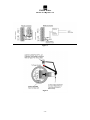
1
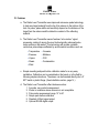
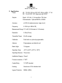
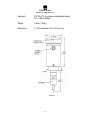
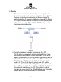
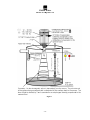
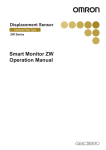
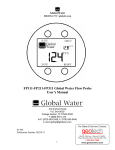
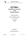
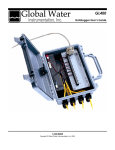
Global Water 800-876-1172 • globalw.com Global Water Instrumentation, Inc. 151 Graham Road P.O. Box 9010 College Station, TX 77842-9010 T: 800-876-1172 Int’l: (979) 690-5560, Fax: (979) 690-0440 E-mail : [email protected] Radar Level Transmitters WL900 01-665 Publication Number 39340712 Revision: A -1- Global Water 800-876-1172 • globalw.com Congratulations on your purchase of the Radar Level Transmitter. This instrument has been quality tested and approved for providing accurate and reliable measurements. We are confident that you will find the Radar Level Transmitter to be a valuable asset for your application. Should you require assistance, our technical staff will be happy to help. Table of Contents I. Checklist • • • • • • • Page 3 II. Inspection • • • • • • 3 III. FCC Information • • • • • • 3 IV. Features • • • • • 4 V. Specifications • • • • • 5 VI. Operation • • • • • • 7 VII. Software Operation • • • • • 8 VIII. Installation • • • • • • 13 IX. Wiring Information • • • • • 15 X. Calibration • • • • • • 17 XI. Maintenance • • • • • • 19 XII. Troubleshooting • • • • • • 19 XIII. Warranty • • • • • • 20 • • * Copyright Global Water Instrumentation, Inc. 2012 -2- Global Water 800-876-1172 • globalw.com I. Radar Level Transmitter Checklist a. Radar Level Transmitter b. Manual II. Inspection a. Your Radar Level Transmitter unit was carefully inspected and certified by our Quality Assurance Team before shipping. If any damage has occurred during shipping, please notify Global Water Instrumentation, Inc. and file a claim with the carrier involved. b. Use the checklist to ensure that you have received everything needed to operate the Radar Level Transmitter. III. FCC Information for Users a. Radar Level Transmitter Sensors have been tested and found to comply with the limits for Class A digital device, pursuant to Part 15 of the FCC rules. These limits are designed to provide reasonable protection against harmful interference when the equipment is operating in a commercial environment. These sensors generate, use, and can radiate radio frequency energy and, if not installed and used in accordance with the instructions, may cause interference with radio communications. Operation of this equipment in a residential area is likely to cause interference that the user will be required to correct. -3- Global Water 800-876-1172 • globalw.com IV. Features a. The Radar Level Transmitter uses improved microwave pulse technology to track any target material from the tip of its antenna to the bottom of the tank. Its power, pulse widths and sensitivity depend on the distance of the target from the antenna and the dielectric constant of the reflecting material. b. The Radar Level Transmitter sensor features “echo marker” signal processing, making it among the most technologically advanced pulse radar system on the market. This technology will provide a reliable continuous pulse shape unaffected by environmental conditions such as: • • • • • Temperature Pressure Vapors Steam Wind • • • • Vacuums Methane CO2 Condensation c. Simple mounting and push-button calibration make for a very easy installation. Calibration can be completed on the bench or in the field by following simple instructions. The sensor can be threaded directly into a 2" NPT metal or plastic flange. (See Installation section, page 14.) d. The Radar Level Transmitter offers features such as: 1. Accurate, non-contact measurement 2. Works in conditions where ultrasonic is not acceptable 3. Pulse radar measurement range 10” to 50’ 4. Simple push-button calibration 5. Standard 4-20mA signal output 6. Optional RS485 digital output -4- Global Water 800-876-1172 • globalw.com V. Specifications Power: AC: 115 VAC, 60 Hz or 230 VAC, 50 Hz (± 20%), 1.7 VA DC: 12 to 30 VDC, 0.07 Amps max. @ 24 VDC Outputs: Signal: 4-20 mA, 6.1 uA resolution; 750 ohms Communication: Optional RS232 or RS485 Accuracy: ±0.25% of maximum sensor range (in air) Frequency: 6.3 GHz (or 5.8GHz CE) Measurement Range: 10” to 50’ (0.254 meters to 15.2 meters) Resolution: 0.22in (5.7mm) Transmitter Power: 50 uW average Calibration: Push-button or optional programmable Antenna: Polypropylene over dielectric rod Beam Angle: 12 degrees Operating Temp: -40°C to 60°C (-40°F to 140°F) Operating Pressure: 150 psi max Installation Category: Class II Process connection: 2” NPT Conduit Entry: 1/2” NPT standard Housing: Aluminum or 316L stainless steel Ingress Protection: NEMA 4 (IP65) -5- Global Water 800-876-1172 • globalw.com Approvals: FCC Part 15 - low-power communication device CE – 5.8GHz Models Weight: 3.6Lbs (1.63Kg) Dimensions: 4” (10cm) diameter x 18” (45.7cm) long Figure 1 -6- Global Water 800-876-1172 • globalw.com VI. Operation a. The microwave rod antenna is stimulated by an electromagnetic pulse transmitter and sends very short pulses to a target. The pulses reflect from the target and then they are received back by the same antenna. The electrical signal from the antenna is amplified and processed. The distance to an object is calculated and then converted to 4-20 mA. Optionally, level information is also sent to a PC via RS232 or RS485 for diagnostic data logging and programmable set-up. Figure 2 b. Turning the low dielectric materials operation mode ON or OFF: The ON mode is recommended to eliminate multiple reflections in tanks and for materials with a dielectric constant lower than 4. To turn the low dielectric materials mode ON, push the calibration button and hold until the LED light flashes yellow, then red, and then turns off. Release the button. The blinking green LED light indicates that the low dielectric materials mode is ON. To turn the low dielectric materials mode OFF, push the calibration button and hold until the LED light flashes yellow, then red, then turns off. Release the button. The constant green LED light indicates that the low dielectric materials mode is OFF. The low dielectric materials operation can also be turned ON or OFF with the Radar Level Transmitter software during PC communications, which is recommended. -7- Global Water 800-876-1172 • globalw.com VII. Software Operation a. Click on “START” button, “PROGRAMS”, and select “PROBE_GatewayPC”. b. Select “Start Data Link”. In the program’s main window there will be two bar graphs, displaying the last 8 echoes and the current output. When PC is connected to Probe, the application header displays the Probe ID. When PC is connected to the Radar, the application header displays Radar ID, range, pipe on/off status, pipe diameter and low dielectric filter status. The traffic icon at the screen bottom indicates communication status to probe. c. Pick “Tools" and select one of the following functions: 1. “Select Data Link Protocol” (RS-232/485 or Modbus RTU): Default is RS-232/485. For probe with RS485 port use a converter RS485 to RS232 between your PC and the microwave probes. If those converters do not have external power supply and you use Windows 2000 or XP, go to the port setting (advanced), change the Transmit Buffer to low, and then reboot your PC. For MODBUS RTU use the Holding Register address as follows: a) 108 to read the current from microwave probe b) 100 to read 4 mA calibration c) 96 to read 20 mA calibration 2. Use “Read Sensor ID (Not in Network)” for single probe communication 3. “Add new Sensor” (in network configuration): Choose new ID and “click OK, for network use 4 and higher 4. Remove Sensor “(in network configuration): Choose sensor ID to be removed and click OK 5. “Fix Sensor ID”: Select new Id and then click on “Fix Sensor ID” to remove old ID. Click “STOP” and “START” to update the calibration data. Sensor ID is 2 for single probe and 4 and higher for network, do not use ID 3 6. “Reset Max. Temperature” (Not applicable for microwave probe.) 7. “Empty Tank Distance calibration”: Programmable with accuracy of 0.1" 8. “Full Tank Distance Calibration”: Programmable with accuracy of alarm relay. -8- Global Water 800-876-1172 • globalw.com 9. “Temperature Scale”: (Not applicable for microwave probe.) 10. “Low Dielectric Material”: (choose for low dielectric constant materials, for microwave probes only) 11. “Pipe Mode” On/Off (for microwave probe only) 12. “Select Pipe Diameter” (for microwave probe only) 13. “Damping OFF”: Fast response mode of the probe 14. “Damping ON”: Select damping time d. “ShowCalibData” (Show Calibration Data): Screen displays all calibration parameters. e. The fix point Calibration buttons (the same as using the probe calibration Push Button) are in the top left corner of the screen. “F.T Calib.” is for Full Tank Calibration and “E.T. Calib.” is for Empty Tank Calibration. In this calibration a target has to be used to simulate full or empty tank fix point calibration. f. “Diagnostic” button: Displays all information on probe “errors”. Sensor error is indicated by an unhappy face icon at the bottom of the screen. g. “Echo Chart” button: Displays information on stability of the echoes. Calculated echo peak count basis on peak width voltage is used as an echo correction offset. h. “Echo Profile” button: Displays profiles of your probe. NOTE - when using this feature the probe is not in the measurement mode. To return to measurement mode, exit the echo profile (select x). Wait until you get the Data Link OK (green light on the Probe Status LED). 1. On the “echo profile” you will see a marker where the software picked up an echo and the distance to the target. 2. To change target for different measurement, exit profile screen, wait for updated data, and go to echo profile. The marker will pick up the new target. Freeze screen and select any point on the graph by clicking mouse to display the distance to selected target. 3. 'Save to file' command saves the profile to PROBE_PROFILE file in C:\Program Files\um_probe\ folder. -9- Global Water 800-876-1172 • globalw.com i. “AutoScan” button (only for network): Collects data for all sensors connected in the network. Scanning time for one sensor is 30 seconds. Other functions are disabled in Auto Scan mode. j. “SensorStatusMonitoring” function displays status of selected sensor. 1. Push the “Update_all” command button to display status for all sensors in network. 2. Traffic icon green/red light indicates communication status. 3. All other functions are disabled in this mode. k. “Select COM Port”: Used to select Communication Port on PC. Selected port can be saved to be used as a default when application is run again. l. Other “Tool” menu options: 1. “Low Dielectric Material On”: For low dielectric constant materials such as oils. 2. “Select PIPE”: For microwave propagation in metal pipes, after that click on “Select Pipe Diameter” in “Tools” menu to choose proper diameter of metal pipe. 3. “Window Out”: In case of unwanted reflections this procedure can be used. Make sure that the probe is in fast response mode (“Damping OFF”). Before using the Window Out procedure programmable calibration on full and empty tank is recommended. For the first time users of this procedure, contact with technical support group is recommended. To use the procedure follow this: a) Click on “Echo Profile” button b) Click on “Clear Window Out”, c) Click on “Freeze/Update/Window Out”, d) Using mouse, click on a point before unwanted echo and then on “WindowOutMin”, e) Using mouse, click on a point after the unwanted echo and then on “WindowOutMax”, f) Close the Echo Profile and wait in the Main program for a message “WindowOut” calibration done, g) To activate the “Window Out” procedure, go to the “Tools” menu, click on “Window Out”, and wait for the conformation. - 10 - Global Water 800-876-1172 • globalw.com 4. “Full Tank Blanking”: Using full tank programmable calibration, select distance to the probes that covers any unwanted echoes close to the probes. To activate this, go to “Tools” and click on “Full Tank Blanking” and wait for the conformation. 5. “Set Loss of Echo Time”: (Not applicable for microwave probe.) 6. “Damping ON” / “Damping OFF”: In case of waves or turbulence on liquids increase the damping time. This will slow down the probe response. Do not use it for small tanks with fast rate of liquid change. 7. “Solid Material/Liquid Materials”: (Not applicable for microwave probe.) 8. “Vaporized Liquid High Power”: (Not applicable for microwave probe.) 9. “Select Burst Power”: Used to change the transmit pulse width (in microseconds). The selected pulse is used in the dusty and noisy tanks (for solids applications) in case of noise error. 10. “Select Filter”: Used to change the filter width. The filter width defines the range of allowed noise. The echo timer is ignored if it is out of defined filter range. m. “File” menu options: 1. “DataLogging (in Excel format)”: Default is set to ON. Select “DataLogging (in Excel format)” from “FILE” menu to collect history data for current and temperature in MS Excel format. Path for data collection: C:\Program Files\um_probe\GATEWAYPC\DATA\yyyy mm dd\sensorID\ Data is collected for each sensor ID. The current is collected in 1 hour data files and temperature is collected in 24 hours data files. Use chart wizard in MS Excel to create the graph and view current and temperature data. The current data is collected every 0.5 second and temperature is collected every 1 minute. 2. “Profile Logging”: Stores profile every 1 minute. Profile Viewer is used to view stored history profiles. Profiles are stored in MS Excel format in C:\Program Files\um_probe\GATEWAYPC\LOG\year_month_day\sensorID\ directory. - 11 - Global Water 800-876-1172 • globalw.com 3. “Send Profile by EMAIL”: Select to send probe profile by Email. One or thirty minute frequencies of sending can be selected. This option works with Microsoft Outlook Express software. The following Email settings are required: a) “Connect Automatically” option shall be selected for connection to Internet. b) In Outlook Express under the “Tools” menu, select “Options” and then click on “Security Tab”. Make sure that option "Warn me when other application tries to send mail as me" is not selected. - 12 - Global Water 800-876-1172 • globalw.com VIII. Installation a. Direct mounting sensor: simply thread sensor into metal or plastic nozzle. b. Radar unit MUST be installed into a fitting with the antenna pointing downward. (See Figure 3.) Figure 3 c. For very low dielectric constant materials (≈ 2), the radar sensor needs at least 2' from the antenna tip to detect the material. Any buildup on the rod antennas does not deteriorate the performance of the radar sensors. d. Software Installation (Communication for Single or Network level sensors.) 1. Load “Probe_Gateway PC Software” into your PC. (Select SETUP.EXE from installation CD and follow instructions on the screen.) 2. Click on START and under PROGRAMS select “Probe_Gateway PC”. 3. Follow instructions in the online help file or see Software Operation section on page 9. 4. To connect RS232 or RS485 cables. (See Figures 4 and 5, page 14.) - 13 - Global Water 800-876-1172 • globalw.com Figure 4 Figure 5 - 14 - Global Water 800-876-1172 • globalw.com IX. Wiring Information a. Wiring Information 1. Ground shield at one end only. 2. All terminal block wiring must be rated for 250V. 3. Power input wiring must be protected by a 15A double pole circuit breaker. 4. Terminal is for use only with equipment that has no live parts that are accessible. (See Figure 6, page 16.) 5. Terminal is for use with equipment, which maintains basic insulation from hazardous voltage under normal and single fault conditions. (See Figure 6, page 16.) 6. Connection used at the remote end of external circuit. (See Figure 6, page 16.) b. Recommended Wiring: For AC Sensor: Power: Current Output: Communication: For DC Sensor: Power: Current Output: Communication: 3 Wire unshielded 22 AWG, 300 V 1 Pair shielded 24 AWG, 300 V 1 Pair shielded 24 AWG, 300 V 3 Wire shielded 24 AWG, 300 V 1 Pair shielded 24 AWG, 300 V 1 Pair shielded 24 AWG, 300 - 15 - Global Water 800-876-1172 • globalw.com Figure 6 - 16 - Global Water 800-876-1172 • globalw.com X. Calibration a. FULL: Calibrate 20 mA or 4mA. Set near target. (See Figure 7, page 18.) 1. Calibration mode LED color is Green. (For Radar, Low Dielectric Materials has to be off. See step C.) 2. Push button and hold until LED turns Yellow (20 mA) or push button and hold until LED turns Red (4 mA) 3. Release button, observe LED flashes to acknowledge the calibration. b. EMPTY: Calibrate 4 mA or 20 mA. Set Far Target. (See Figure 7, page 18.) 1. Calibration mode LED color is Green. (For Radar, Low Dielectric Materials has to be off. See step C.) 2. Push button and hold until LED turns Red (4 mA) or push button and hold until LED turns Yellow (20 mA) 3. Release button, observe LED flashes to acknowledge the calibration. c. Turn the Low Dielectric Materials operation mode ON and OFF: (This mode is recommended for materials with dielectric constant lower than 4, and to eliminate multiple reflections in the tank.) 1. To turn the Low Dielectric Materials ON, push the calibration button and hold until the LED light flashes yellow, then red, and then turns off. Release the button. The blinking green LED light indicates that the Low Dielectric Materials mode is ON 2. To turn the Low Dielectric Materials OFF, push the calibration button and hold until the LED light flashes yellow, then red, and then turns off. Release the button. The constant green LED light indicates that the Low Dielectric Materials mode is OFF. 3. The low dielectric materials operation can also be turned ON or OFF with the Radar Level Transmitter software during PC communications, which is recommended. - 17 - Global Water 800-876-1172 • globalw.com Figure 7 - 18 - Global Water 800-876-1172 • globalw.com XI. Maintenance a. The unit must be checked periodically. The suggested maintenance rate depends on the installation area. Check batteries for correct voltage periodically. XII. Trouble Shooting Issue: Radar Level Transmitter not operating correctly Internal piping, deposits on the antenna, multiple reflections or reflections from the wall can all interfere with the proper operation of the radar sensor. a. Verify power source is supplying correct voltage. b. Verify antenna is clean. Other issues c. Call us for tech support: 800-876-1172 or 979-690-5560 (many problems can be solved over the phone). Fax: 979-690-0440 or E-mail: [email protected]. Be prepared to describe the problem you are experiencing including specific details of the application and installation and any additional pertinent information. d. In the event that the equipment needs to be returned to the factory for any reason, please call to obtain an RMA# (Return Material authorization). Do not return items without an RMA# displayed on the outside of the package. Clean and decontaminate the Radar Level Transmitter, if necessary. Include a written statement describing the problems. Send the package with shipping prepaid to our factory address. Insure your shipment, as the warranty does not cover damage incurred during transit. - 19 - Global Water 800-876-1172 • globalw.com e. When calling for tech support, please have the following information ready: 1. 2. 3. 4. 5. XIII. Model #. Unit serial number. P.O. # the equipment was purchased on. Our sales order number or the invoice number. Repair instructions and/or specific problems relating to the product. Warranty a. Global Water Instrumentation, Inc. warrants that its products are free from defects in material and workmanship under normal use and service for a period of one year from date of shipment from factory. Global Water’s obligations under this warranty are limited to, at Global Water’s option: (I) replacing or (II) repairing; any products determined to be defective. In no case shall Global Water’s liability exceed the products original purchase price. This warranty does not apply to any equipment that has been repaired or altered, except by Global Water Instrumentation, Inc., or which has been subject to misuse, negligence or accident. It is expressly agreed that this warranty will be in lieu of all warranties of fitness and in lieu of the warranty of merchantability. b. The warranty begins on the date of your invoice. - 20 -