1
Digital Timing
Relay/Counter
700-HXM
User Manual
Important User Information
!
"
#$ %%
! "
&
&
'
ATTENTION
$
)
'
N (
N (
N (
IMPORTANT
$
European Communities (EC)
Directive Compliance
$
*+
+,++$
EMC Directive
*-
./01120+*
+
*
!+3*"
'
N +4566.% 7+3*8#+
9
78$
+
N +4566.7 7+3*8#$
9
78$
+
Low Voltage Directive
*-
:10710++*;<
+42%6%6 %
9
%
#
&
Preface
Manual Objectives
:66 =>3-
&0*
-
Who Should Use This
Manual
?
Counter/Timer Mode
Explanation
$
'
@A4 @&
*
-@ABB +@A
B@
C@A40ABB )
&
*
$
'
4B*D
For further information, see page 3-17.
For Further Information
&
#
N 9
:66 #661 +4 9
i
Publication 700-UM001A-EN-D June 2001
Preface
ii
Publication 700-UM001A-EN-D - June 2001
Table of Contents
Preface
!
Chapter 1 — Product Overview
"!
#$#
Chapter 2 — Product Features
"%& '$#
"() '$'
'$'
Chapter 3 — Application
Examples
$
*)
+,,$-.%))/
&
0$#
$
*)
+,,$-.%))/
&
0$'
)+,,$-.%))/
&
!!
)1
0$0
%
!2
0$0
Chapter 4 — Installation
3)
4$#
) 4$#
Chapter 5 — Troubleshooting
%& 5$#
Chapter 6 — Precautions
6
7$'
36
7$0
1
8
!9,: 7$4
Appendix
6
2 3
$#
i
Publication 700-UM001A-EN-D - June 2001
Table of Contents
ii
Publication 700-UM001A-EN-D - June 2001
Chapter
1
Product Overview
Bill of Material
1
?:66 =>3-
&0*
'
Item Cat. No.
Description
Quantity
700-HXM
Digital Timing Relay/Counter
1
700-HN141
Flush Mounting Adapter
1
—
Rubber Gasket
1
—
6-Language Instruction Sheet
1
Publication 700-UM001A-EN-D - June 2001
1-2
Product Overview
Publication 700-UM001A-EN-D - June 2001
Chapter
2
Product Features
=
:66 =>3-
&0*
'
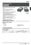
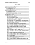
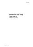
Basic Display
Operation Display 2
N0. 1 Display
Displays the present value
or parameter type. When
totalizing count is displayed,
the leftmost 4 digits of the
8-digit totalizing count will
be displayed (Zeros
suppressed)
Operation display 1
Displays the time unit when the timer
function has been selected
Indicator
RST
OUT
TOTAL
N0. 2 Display
Displays set value or set
value of the parameter.
Displays the rightmost 4
digits of the count value (8
digits) when 700-HXM is
used as a totalizing counter.
Zeros suppressed)
Example
5h 30 min
123.4 s
Level Key
Displays the present value or
parameter type. When totalizing
count is displayed, the leftmost
4 digits of the 8-digit totalizing
count will be displayed (Zeros
suppressed)
Mode Key
Press this key to select
parameters within
each level.
Meaning
Lit during reset using
reset input or Reset Key.
Lit when control output is
ON.
Lit when totalizing value
is displayed.
Down Key
Each press of this key decreases
values displayed on the No. 2
display. Hold down this key
continuously to decrease values
quickly. Also returns setting
items.
Up/Reset Key
Each press of this key
increases values displayed on
the No. 2 display. Hold down
this key continuously to
increase values quickly. Also
advances setting items.
Reset Function
To reset the present value,
press this key while the
present value is displayed. If
this key is pressed while the
totalizing count value is
displayed, the totalizing count
value and the present value
will be reset.
1
Publication 700-UM001A-EN-D - June 2001
2-2
Product Features
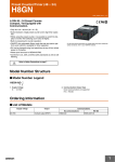
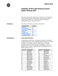
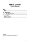
Block diagram
I/O Functions
Inputs Counter
inputs
CP1/CP2
Reset
Timer inputs Start
Reset
Outputs
Publication 700-UM001A-EN-D - June 2001
Gate
OUT
Receive count signals.
Receive increment, decrement, individual, and
quadrature inputs.
In increment mode and decrement mode, CP1 is used for
the count input and CP2 is used for count prohibit input.
Resets the present value. (Totalizing count value is not
reset.)
(In increment mode or increment/decrement mode, the
present value returns to 0; in Decrement Mode the
present value returns to the set value.)
The count input is not received during resetting.
The RST indicator is lit during resetting.
Starts timing.
Resets the timer. (In elapsed time mode the time returns
to 0; in remaining time mode, the time returns to the set
value.)
During resetting, timing stops and the control output
turns OFF.
The RST indicator is lit during resetting.
Prohibits timing operation.
Output made according to the output mode setting when
the set value is reached.
Chapter
3
Application Examples
Set-up Procedure—Using
the 700-HXM Digital Timing
Relay/Counter as a counter
Typical Application Examples
Set-up Procedure
#
$
$
#%
&
#
! "
Typical Application
&/01
"/+
'('
)
*+
'('
)*+
-
+
.
+
+
+-
+
.
+
+-
'(
'(
'(
'(
'
-
-
#%
!
#
$
!//
,
$
$)$-
$-
Confirming Set Values
%%
%
(
(
1
Publication 700-UM001A-EN-D - June 2001
3-2
Application Examples
Set-up procedure—using
the 700-HXM Digital Timing
Relay/Counter as a timer
Typical Application Examples
Set-up Procedure
#
$
$
#%
&
! "
#
Typical Application
//32222
4 +
+
5+
0
"/+
'
)
*+
.
+
%
-
+
.
+
2222
*+-
'(
++
.
++
+
+
*++-
'(
+
+-
'(
+
+-
'(
'(
-
#%
!
#
$
.
$
!//
$)$-
,
$
$-
Confirming Set Values
%%
%
(
(
Publication 700-UM001A-EN-D - June 2001
Application Examples
Setting 700-HXM Digital
Timing Relay/Counter
specifications after turning
on power.
3-3
$
)
%
&'$!(
!
%
"#!
%
%
&
!
)
%
!
%
!*+,-.
"!$
!
/!
A
*
E
Description of Levels
Operation Level
N This level is displayed when you turn the power ON. You can move to the protect level, initial
setting level, and adjustment level from the operation level.
N Normally, select this level during operation.
N During operation, the present value, set value, totalizing count value, and setting number of
SV-bank can be monitored using the
key.
Publication 700-UM001A-EN-D - June 2001
3-4
Application Examples
Adjustment Level
N To select this level, press the
key once for less than one second.
N This level is for entering set value (SV 0…3) for operation. This level contains parameters for
set value of SV-bank, and cycle time (timer Z mode).
N You can move to the top parameter of the operation level, protect level, or initial setting level
from here.
Initial Setting Level
N To select this level, press the
Key for at least three seconds in the operation level or
adjustment level.
N This level is for selecting the function, input mode, time range, timer mode, output mode,
output time, counting speed, input signal width, decimal point position, prescale value, and
rising/falling edge for input signal.
N You can move to the advanced function setting level from this initial setting level. To return to
the operation level, press the
key for at least one second.
Protect Level
N To select this level, simultaneously press the
and
keys for at least three seconds
(default value). This level is to prevent unwanted or accidental modification of parameters.
Protected levels will not be displayed, and so the parameters in that level cannot be modified.
Advanced Function Setting Level
N To select this level, you must change the initial settings in the protect level to "0" and then
enter the password ("-169") in the initial setting level.
N This level is for initializing settings, enabling SV-bank and totalizing counter use, setting
display auto-return time, and move- to-protect-level time.
N You can move to the initial setting level from this level.
Parameters—Operation Level
Publication 700-UM001A-EN-D - June 2001
$
$
Application Examples
3-5
A44%
47
*
0
,
4%
47
*
0
9
(
F
(
F
A4
. (
4%
47
*
6*
1
-!"7&897:;<
+
1
$
$
*
1
1
/!"&/!"/!"
/!"&&89/!"
Refer to Input/Output Mode Settings on page 3-17 for information on totalizing counter operation.
G< !m-sp"
!
""#$% !%$&'
('&$ < !<6H1"
< !<6H1"
)
Publication 700-UM001A-EN-D - June 2001
Application Examples
$
$
3-6
Adjustment Level
!
"$/
"$!
"$"
"$&
&'
+
)
;<6
1sp-0, sp-1, sp-2, sp-3"
% )
""#$% !%$
&'('&$ ,
< !<6
1"E
!<6
1"
)
< "'cyti*
"'
""#$$%
(('%
$&$ %+%
A40ABB )
!C"
*
A40ABB )
)
A4 Publication 700-UM001A-EN-D - June 2001
Application Examples
3-7
$(# "
'$''
&& "
'
'
+
'
=
'
$>
%
>/=
!//=
'
+
(
.
Refer to the Input/Output Mode Settings on page Input/Output Mode Settings for information on ON/OFF-duty
adjustable repeat cycle mode operation.
Parameters—Initial Setting Level
!"#
$%
&
'
('
'
'
'func*
:66 =>3-
&0*
Publication 700-UM001A-EN-D - June 2001
3-8
Application Examples
,
cntm*
F*
0
F
E
:66 =>3-
&0*
$
*9%!
"
Refer to Input/Output Mode Settings on page 3-17 for information on ON/OFF-duty adjustable repeat cycle mode
operation.
Refer to Input/Output Modes and Count Values on page3-16 for information on input mode operations.
-timr*
$
""#$%'%
$&$ E
:66 =>3-
&0*
.timm*
$
""#$%'%
$&$ E
:66 =>3-
&0*
/
(0'outm*
$
""#$%'%
$&$ '
E
:66 =>3-
&0*
Refer to Input/Output Mode Settings on page 3-17 for information on output mode operations.
1
(0'outm*
$
""#$%'%
$&$ '
E
:66 =>3-
&0*
Refer to Input/Output Mode Settings on page 3-17 for information on output mode operations.
Publication 700-UM001A-EN-D - June 2001
Application Examples
3-9
2
otim*
$
""#$%
('
('%$&$ 3#$
%
(('%$&$ 45
E :66 =>3-
&0*
!66%H////"
A *D
$
F6F
F6F
6
cnts*
$'
""#$%'%
$&$ '
E
:66 =>3-
&0*
!16=(05=("
*9%*97
16=(
E
16=(
7,
8$iflt"
!760%"
E
76
E
76
)9':dp
dp*
dp
$'
""#$%
'%$&$ '
9<<< !<6
1"
(
9
D
'pscl*
Publication 700-UM001A-EN-D - June 2001
3-10
Application Examples
$
'&
""#$%'%
$&$ '
*
!666%
H////"
+'VVVV
75
)
65
% 7 667!65?75"
/9+
"9
@
,
;edge*
$
# ""#$$%
%
$&$ ''
*9%
:66 =>3
$
*97
*9%
*97
A4
Refer to Input/Output Modes and Count Values on page 3-16 for information on input mode operations.
&4&'0'<&amou*
$# ""#$$%
'%
'&)
(
0
! %2/"
Publication 700-UM001A-EN-D - June 2001
Application Examples
3-11
Parameters—Advanced Function Setting Level
!+
1
"$>(
&*
1
8
>
+
9A>
>
>>
+
,init
,
A4
(
!=npsu*
F< F
A4
<6
1
< !<6
1"
)
,
=tcnu*
(
A4
(
(
. (
4%
47
. .9
"4ret*
$
)
9<0<
!
'%H//"
$
ABB
/&
'&prlt*
Publication 700-UM001A-EN-D - June 2001
3-12
Application Examples
$
1
,
!1H16"
Parameters—Protect Level
'(0"#
,
+
B
+
'(
,
++
)
%
'&(
,
%
(
'1(2%
,
%
,
4>'oapt*
Setting level
0
1
Operation level
PV/SV
Not protected
Not protected
2
Not protected
3
Display only
Adjustment level
Other
Not protected
Not protected
No display, no level
shift
No display, no level
shift
Not protected
No display, no level
shift
No display, no level
shift
No display, no level
shift
Not protected:Display and setting changes are possible.
Display only:Display is possible.
No display, no level shift: Display and level shifts are not possible.
The initial setting level is 0 and no protection is given at this setting level.
,'icpt*
3
Setting
Initial setting
level
0
1
2
OK
OK
NO
OK: Move to other levels possible
NO: Move to other levels not possible
The default setting is 1.
Publication 700-UM001A-EN-D - June 2001
Advanced
function setting
level
OK
NO
NO
Application Examples
3-13
$'wtpt*
&
Setting
OFF
ON
Meaning
Settings can be changed by key operation.
Settings cannot be changed by key operation. (Only protect level
settings can be changed.)
The default setting is OFF.
.-3"'rpt*
9
&
D
Setting
OFF
ON
Meaning
PV and totalizing count values can be reset by the Reset Key.
PV and totalizing count values cannot be reset by the Reset Key.
The default setting is OFF.
Publication 700-UM001A-EN-D - June 2001
3-14
Application Examples
!"
#
$!!
$!
$!!
$!!
.5-.
-$!
.
.!
+
+
.
!!
$!!
%&$'()
1
+
1
-.&/
0
*-.3
*-.$
*-.6
*-.
-.&/
0
$!!
"&$'(#
1
+
*
+
*
+
,
-./
0
*,
*
,
+
*,
*
2
&
*
&
*$((!
4&&
&
0
$!
!!
1
1
* 3!
- !
Publication 700-UM001A-EN-D - June 2001
-6!
*9
*:
1
*
*2
*
*8
1
1
*7
*
1
See note 3, page w
75
1
1
/7<?
<?<?
=<
$!!
*
*;
*7<
*<
*<
*=<
*2
*9
*;
*>
7
*$!3$((!((
*3!33((!((
/3!
/3
!
7
* 3@+
*A0@+
"
?
?
#
*63
*$
2
*3
*3!3
*3!33
*3!333
*3!33$(!(((
*7
*7
4
!
Application Examples
3-15
%+
+*%
&
5B
+
#
E
%!+
-#/
-#!
-#"
F#&
-#/
-#!
-#"
$/
!
$!
!
- (>
->
$"
!
,
-,
-,
$&
!
4
$>(
4
+
+
D
)
B
+
'
+
!
3
!'
+
+
-/32222
'
C
->22232222
*+
++
+D
-////32222
-///32222
-//322227+7
-/322227
-/+//
22+92
-///+
2292+
*+
+D
-/=
!//= "*+
->>>>
->>>>%
->>>>
->>>>
->>+>>
->>>>+
->>>>+
->>>>
->>>>
&/
%
Publication 700-UM001A-EN-D - June 2001
3-16
Application Examples
Input/Output Modes and Count Values
4
'=I
;IA
Up (Increment) Mode c
Input UP
edge
'!-'
'!
0
#
'"
0
#
Down (Decrement) Mode c
'!-'
'"-'
'!
0
#
'"
0
#
'
'"-'
'
>!
9
>"
8
'
>&
'
&
>8
"
>9
!
/
DOWN
/
&3
+
/
&3
+
/
'!-'
'!
0
#
'"
0
#
'
'"-'
'
>!
&RXQW
>"
'
>&
>8
>9
Up/Down C Quadrature Input c
Up/Down B Individual Input
'!
0
#
'!
0
#
'"
0
#
'"
0
#
&
'
"
&
!
/
"
"
/
!
&
'
"
!
!
/
&
"
"
!
/
c(A) indicates the minimum signal width and (B) requires at least 1/2 the minimum signal width. If these conditions
are not met, a counting error (+1 or -1) may occur.
Publication 700-UM001A-EN-D - June 2001
Application Examples
3-17
Input/Output Mode Settings
Counter Function
$
A4
A4
B A
4
'
';
'A
Input Mode
Up
Output
mode
Down
Up/Down B.C
,
2222
$
/
>222
)
!!!!
+,
$
*!!!
'
>
>
>
>
>
>
Publication 700-UM001A-EN-D - June 2001
3-18
Application Examples
Totalizing Counter Operation
,
*
1
(
$
!;+
*
1
N (
!
"
9<
N E
(
9<
N (
6H////////$
(
////////
6$
6
////////
Timer Function
A Mode: Signal ON-Delay c
B Mode: Repeat Cycle c
G
G
,
'
$
.
/
$
/
,
'
$
.
/
$
/
*+
*+
D Mode: Signal OFF-Delay
E Mode: One Shot
G
G
,
'
$
.
/
$
/
,
'
$
.
/
$
/
F Mode: Accumulative
*+
*+
Z Mode: ON/OFF-Duty Adjustable Repeat Cycle
,
'
$
.
/
$
/
G
,
'
'
+
= +
.
/
'
+
= +
/
*+
*+
G
cOne-shot output or HOLD output can be selected for output:
Publication 700-UM001A-EN-D - June 2001
Application Examples
3-19
Z Mode
A
)
)
%
A4
!J"
*
=
/!//
=4
+/7
4
+
/ /=7
4
!//=7
'
+
=
'
+
'
Publication 700-UM001A-EN-D - June 2001
3-20
Application Examples
Publication 700-UM001A-EN-D - June 2001
Chapter
4
Installation
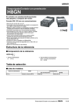
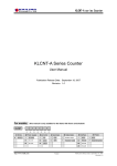
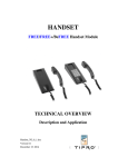
Terminal Arrangement
RS-485
Not
Output
connected
CP1/
Start
24-VDC
power
supply
CP2/
Gate
Reset
Contact
inputs
Open-collector inputs
Wiring
,
31
9;+++H
9;+++H
1
Publication 700-UM001A-EN-D - June 2001
4-2
Installation
Publication 700-UM001A-EN-D - June 2001
Chapter
5
Troubleshooting
Display
E
No. 1 display No. 2 display Error
contents
e111
No display
Memory error
(RAM)
e111
sum
Memory error
(EEP)
e1
No display
CPU error
- - - Set value
Present value
lashes displayed or no underflow
0.5 s)
display
Countermeasure
Turn the power OFF and ON again. If
normal operation is still not restored, it
may be necessary to repair or replace the
700-HXM Digital Timing Relay/Counter. If
normal operation is restored by turning
the power supply OFF and ON, it is
possible that there is noise interference.
Check that there is nothing in the vicinity
that may be the source of noise.
This is not an actual error. This display
indicates that the present value has
dropped to a value less than -999. Reset
using reset input or pressing the Up Key
when "- - - -" is displayed.
4
'+9<0<9<
1
Publication 700-UM001A-EN-D - June 2001
5-2
Troubleshooting
Publication 700-UM001A-EN-D - June 2001
Chapter
6
Precautions
ATTENTION
ATTENTION
ATTENTION
ATTENTION
1
-
)
-
*
,
-
-
-
)
-
Publication 700-UM001A-EN-D - June 2001
6-2
Precautions
Publication 700-UM001A-EN-D - June 2001
!"
#
$%"&' !"
(
#
)
'
*#&
+&
#'&,
#-
&
*
&
)
'
./0"1 *
$2./01" *
&
#
&
#
'
*'
3&
&'
&
#
# 4
,
*
#5&
+
&
Precautions
6-3
-
3
. *
$
A4
/ E
A4
!%5"
-
1 B
2 ;
:66 =>3-
&0*
A4
!
"
%
A4
In Counter Operation
E
A4
In Timer Operation
E
-
A4
,9'
-AE4'
9
+
!9
I6"
4
'E-AE4
Publication 700-UM001A-EN-D - June 2001
6-4
Precautions
A4
!6"
ABB
&
D
A4
"E
! "-B
A4
"E
!
"+C
ABB
E
A4ABB
&'
!!(
#$
#%%
!
!
"
"
A4ABB
%5
A4ABB
E
A4
!
"
:66 =>3-
&0*
7%6H726
A4!"B
A4
75.$
75.
A4
7%6726!4
75/"$
75.
E
:66 =>3-
&0*
B!
"
!
%66
:66 =>3-
&0
Publication 700-UM001A-EN-D - June 2001
Precautions
6-5
*
A4"
,
:66 =>3-
&0*
ABB
Minimum reset signal width
1 ms
20 ms
Output delay time
3.7 …6.0 ms
19…21 ms
!
Control output
Contact output
Max. counting speed
30 Hz
5 kHz
Output delay time c
17.3…18.9 ms
3.5 …5.2 ms
c The variation in delays is due to different modes and conditions.
Flush Mounting
Adapter
Rubber Gasket
Panel
:66 =>3-
&0*
K
!
4+3G!"$922"$
Publication 700-UM001A-EN-D - June 2001
6-6
Precautions
!
:66 =>3-
&0*
"
B 9-! "
9 4A
9 4*
-
1 !
"
>
Publication 700-UM001A-EN-D - June 2001
Appendix
Parameters List
B
Protect Level
1
Parameter name
Parameter Setting range
Operation/Adjustment
Protection
Initial Setting
Protection
Setting Change
Protection
Reset Key Protection
oapt
033
Default Unit Set
value
value
0
icpt
02
1
wtpt
onoff
off
rpt
onoff
off
Publication 700-UM001A-EN-D - June 2001
Appendix-2
Operation Level
Parameter
name
Present value
(PV)/
Set Value (SV)
Parameter
PV
SV
Counter
Timer
Counter
Timer
(Output
mode: A,
B, D, E, F)
Timer
(Output
mode: Z)
PV
Totalizing count value
SV-bank
m-sp
Publication 700-UM001A-EN-D - June 2001
Setting (display) range
-99939999)---- (PV<-999)
0. 000
. 9. 999
.
s
0. 00
. 99. 99
. s
0. 0. 999. 9. s
039999s
00039959 min. s
Default
value
0
0. 000
0. 00
0.. 0
0
0 00
0. 0. 3999. 9. min.
00039959 h min.
0. 0
0 00
0. 03999. 9. h
039999 h
039999 (Input mode=Up or Down)
-99939999 (Input mode=Individual or
quadrature)
0. 000
. … 9. 999
.
s
0. 00 …99. 99
. s
0. 0. …999. 9. s
0…9999 s
000 …99:59 min. s
0. 0
0
0
0
0. 000
.
0. 00
0. 0.
0
000
0. 0…999. 9. min.
000…99:59 h min.
0. 0.
000
0..).0…999. 9. h
0…9999 h
03100
0.. 0
0
0
Same as for PV in the above PV/SV column.
0399999999
0)1)2)3
0
0
Unit
Second
Second
Second
Second
Minute:
Second
Minute
Hour:
Minute
Hour
Hour
Second
Second
Second
Second
Minute:
Second
Minute
Hour:
Minute
Hour
Hour
%
Set
value
Appendix-3
Adjustment Level
Parameter name Parameter Setting range
SV 0
sp-0
SV 1
sp-1
SV 2
sp-2
SV 3
sp-3
Cycle
time
Timer
cyti
(Output
mode=Z)
Default Unit
value
Same as for PV in the above PV/
SV column.
Same as for PV in the above PV/
SV column.
Same as for PV in the above PV/
SV column.
Same as for PV in the above PV/
SV column.
0. 000
. … 9. 999
.
0. 00 …99. 99
. s
0. 0. …999. 9. s
0…9999 s
000 …99:59 min. s
0. 0…999. 9. min.
000…99:59 h min.
0..).0…999. 9. h
0…9999 h
Set
value
0. 000
.
0. 00
0. 0.
0
000
Second
Second
Second
Second
Minute
:
Second
0. 0.
Minute
0 0 Hour:
0
Minute
0.. 0
Hour
0
Hour
Initial Setting Level
Parameter name
Counter/Timer selection
Input mode
Parameter
func
cntm
Time range
timr
Timer mode
Output mode for counter
function
Output mode for timer
function
Output time Counter
Timer
timm
outm
Setting range
cnt/tim
up/down/ud-b/
ud-c
-.---s/--.--s/
---.-s/----s/
--min--s/
---.-min/
--h--min/
---.-h/----h
up down
Q/I/F/N
Default value
cnt
up
Unit
--.--
Second
outm
D/E/G/H/I/
a
otim
0. 01
. …99. 99
.
0. 00…99. 99
.
0. 50
0. 00
Set value
up
n
Second
Second
Publication 700-UM001A-EN-D - June 2001
Appendix-4
Parameter name
Counting speed
Input signal width
Decimal point position
Prescale value
Input signal edge
Move to function setting
level
Parameter
cnts
iflt
dp
pscl
edge
amou
Setting range
30 h skh
20 ms1 ms
///
0. 001 … 9. 999
.
up down
-999 …9999
Default value
30 h
20 ms
---1. 000
up
0
Unit
Set value
Advanced Function Setting Level
Publication 700-UM001A-EN-D - June 2001
Parameter name
Parameter Setting range
Parameter initialization
SV-bank used
Totalizing counter used
Display auto-return time
Move-to-protect-level time
init
mspu
tcnu
ret
prlt
on off
on off
on off
off1…99
3…30
Default Unit
Set
value
value
off
off
off
off
Second
3
Second
Appendix-5
Publication 700-UM001A-EN-D - June 2001
Back Cover
Publication 700-UM001A-EN-D - June 2001 1
© 2001 Rockwell International Corporation. Printed in the U.S.A.