1
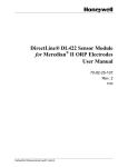
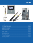
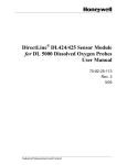
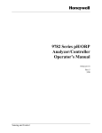
Analytical Products Demonstration Kit Manual 70-82-25-150 May 2014 Revision 1 Honeywell Process Solutions Notices and Trademarks Copyright 2014 by Honeywell Revision 1 May 2014 While the information in this document is presented in good faith and believed to be accurate, Honeywell disclaims any implied warranties of merchantability and fitness for a particular purpose and makes no express warranties except as may be stated in the written agreement with and for its customers. In no event is Honeywell liable to anyone for any indirect, special, or consequential damages. The information and specifications in this document are subject to change without notice. Honeywell, TDC 3000, SFC, SmartLine, PlantScape, Experion PKS, and TotalPlant are registered trademarks of Honeywell International Inc. Other brand or product names and service marks are the property of their respective owners. Honeywell Process Solutions 1860 Rose Garden Lane Phoenix, AZ 85027 ii Analytical Products Demonstration Kit Manual Revision 1.0 About This Document Abstract This document provides descriptions for Preparation, Overview, Key Features, Operator Interface Communications of UDA2182 and Sensors. Release Information Analytical Products Demonstration Kit Manual, # 70-82-25-150 (this document) – 1st Release, May 2014 Reference Information The following list identifies publications that may contain information relevant to the information in this document. 70-82-25-119, UDA2182 Universal Dual Analyzer Product Manual 70-82-25-126, UDA2182 Communications User Guide 70-82-25-137, Process Instrument Explorer Configuration Software User Manual Patent Notice The Honeywell ST 800 SmartLine Pressure Transmitter family is covered by one or more of the following U. S. Patents: 5,485,753; 5,811,690; 6,041,659; 6,055,633; 7,786,878; 8,073,098; and other patents pending. Support and Contact Information For Europe, Asia Pacific, North and South America contact details, see back page or refer to the appropriate Honeywell Solution Support web site: Honeywell Corporate www.honeywellprocess.com Honeywell Process Solutions www.honeywellprocess.com/pressue-transmitters/ Training Classes http://www.honeywellprocess.com/en-US/training Telephone and Email Contacts Area Organization United States and Canada Honeywell Inc. Global Email Support Honeywell Process Solutions Revision 1.0 Phone Number 1-800-343-0228 Customer Service 1-800-423-9883 Global Technical Support [email protected] Analytical Products Demonstration Kit Manual Page iii Symbol Definitions The following table lists those symbols used in this document to denote certain conditions. Symbol Definition This CAUTION symbol on the equipment refers you to the Product Manual for additional information. This symbol appears next to required information in the manual. WARNING PERSONAL INJURY: Risk of electrical shock. This symbol warns you of a potential shock hazard where HAZARDOUS LIVE voltages greater than 30 Vrms, 42.4 Vpeak, or 60 VDC may be accessible. Failure to comply with these instructions could result in death or serious injury. ATTENTION, Electrostatic Discharge (ESD) hazards. Observe precautions for handling electrostatic sensitive devices Protective Earth (PE) terminal. Provided for connection of the protective earth (green or green/yellow) supply system conductor. Functional earth terminal. Used for non-safety purposes such as noise immunity improvement. NOTE: This connection shall be bonded to protective earth at the source of supply in accordance with national local electrical code requirements. Earth Ground. Functional earth connection. NOTE: This connection shall be bonded to Protective earth at the source of supply in accordance with national and local electrical code requirements. Chassis Ground. Identifies a connection to the chassis or frame of the equipment shall be bonded to Protective Earth at the source of supply in accordance with national and local electrical code requirements. Page iv Analytical Products Demonstration Kit Manual Revision 1.0 Contents 1.1 Demonstration Equipment .......................................................................................................... 2 1.2 Before Meeting the Customer ..................................................................................................... 2 1.3 Quick Product Overview of UDA2182 ....................................................................................... 2 1.4 UDA2182 Key Features and Customer Value ............................................................................. 3 1.5 Describe the 2 Channel Process Variable (PV) and Input/Output (I/O) Measurement Capability ........................................................................................................................................... 4 1.6 Describe the Operator Interface (Power on) ................................................................................ 4 1.7 #2. Configure for pH measurement on Channel #1 and for Conductivity measurement on Channel 7 1.8 Process Instrument Explorer Software and Digital Communications.......................................... 16 1.9 Summarize UDA2182 Features Review features that add value for the end user: ...................... 19 1.10 Demo of Honeywell Analytical Sensor Capabilities ............................................................... 20 Revision 1.0 Analytical Products Demonstration Kit Manual Page v Tables Table 1 – Configuration Parameters ______________________________________________________ 7 Table 2 - Conductivity and Resistance Values _____________________________________________ 26 Figures Figure 1 - UDA Connections ____________________________________________________________ 1 Figure 2 - UDA2182 Connection terminals _________________________________________________ 4 Figure 3 - Process Instrument Explorer Menu (PIE) _________________________________________ 16 Figure 4 - Internet Communications _____________________________________________________ 17 Figure 5 - UDA Web Access ___________________________________________________________ 18 Figure 6 - Terminal Designations for Durafet III Electrodes ___________________________________ 20 Figure 7 - HB Series cut-away _________________________________________________________ 21 Figure 8 - Wiring for UDA2182 installation _______________________________________________ 22 Figure 9 – Wiring for HPW7000 _______________________________________________________ 23 Figure 10 - Wiring for DO with Quick Disconnect Option ____________________________________ 24 Figure 11 - Conductivity Wiring for Quick Disconnect_______________________________________ 25 Page vi Analytical Products Demonstration Kit Manual Revision 1.0 Honeywell Analytical Demonstration Kit Procedures 1. 2. 3. 4. 5. 6. 7. 8. Introduce the UDA2182 Analyzer Describe the Physical Characteristics (Un-Powered unit) Describe the Terminal Wiring assignments – PV and I/O (Un-Powered unit) Describe the Operator Interface (Power on) Demonstrate Analyzer Set-up Channel 1 pH and Channel 2 Conductivity Demonstrate or discuss digital remote communication and configuration Summarize Key End User Benefits with UDA2182 Analyzer Describe key features of analytical sensors included in the kit The demo procedure assumes that you are familiar with the operation of the UDA2182. PREPARE THE UDA2182 ANALYZER FOR DEMONSTRATION: Analyzers may also be demonstrated with actual pH electrodes or conductivity cells included. Wiring for the pH and conductivity probes are shown in the quick start and operation manuals. The quick start manual is attached. However if you would like to use these for shows, you can jumper the boards are follows: 15 15 14 14 10 13 13 5 KOhm 12 12 11 11 9 8 10 10 Jumper 7 99 6 88 77 8.5 K Ohm 5 8.5 K Ohm 66 55 4 3 44 33 2 22 1 11 UDA PH CONNECTIONS UDA CONDUCTIVITY CONNECTIONS Figure 1 - UDA Connections Simulated pH Input: On the pH input board jump terminals 8 and 10 to simulate 7 pH (or use the pH simulator included in the demo kit, see page 26 in this manual.) Install an 8.5 K Ohm resistor across terminals 4 and 5 to simulate 25̊C (or set the temperature compensation to manual in the UDA2182). The jumper across terminals 5 and 6 should remain in place. Revision 1.0 Analytical Products Demonstration Kit Manual Page 1 Simulated Conductivity Input: Set the Analyzer Cell Constant to 0.1 (the default). On the Conductivity input board install a 5K Ohm resistor across terminals 7 and 10 to simulate 20 µSiemens/cm (or connect resistance box provided in demo kit, see page 23 in this manual.) and an 8.5 K Ohm resistor across terminals 4 and 5 to simulate 25̊C (or set the temperature compensation to manual in the UDA2182). The jumper across terminals 5 and 6 should remain in place. 1.1 Demonstration Equipment UDA2182 model number included in this kit is UDA2182-PH1-CC2-NN-E-0E0C-EE. This model provides: • inputs (Input #1 for pH measurement and Input #2 for Conductivity measurement.) • 4 to 20ma analog outputs • SPDT alarm relays • Infrared porti o Ethernet/RS485 Modbus Cardii o Printed Manual o PID Control/Advanced Features Option 1.2 Before Meeting the Customer Review all product launch material prior to meeting with the customer. Focus on the competitive differentiator/value and feature/benefit tools to decide which 3-4 key points you will emphasize with that particular customer and then highlight those key points during the demonstration. If you are in doubt contact an Analytical Product Specialist or Product Manager for assistance. 1.3 Quick Product Overview of UDA2182 Give a brief description of the UDA2182 with emphasis on features relevant to the specific customer need and how the unique new features of the UDA2182 meet those needs. • Single or Dual measurement in any combination of pH (Glass and Durafet), ORP, Contacting Conductivity and ppm / ppb Dissolved Oxygen probes. • Graphic backlit LCD display providing continuous readout of process variables, alarm and diagnostic status. • Infrared communications port enables fast and secure configuration via a Pocket PC or Infra red portequipped laptop or desktop computer using Process Instrument Explorer software. • Ethernet and RS485 communications provide IP addressing capability for continuous display of process variable data, event history and more. i Demonstration Units are not supplied with Pocket PC’s or PIE Software – these should be purchased by the Demonstrator / UDA owner if interested in demonstrating this capability. ii Cables and PIE software are not included. PIE is not needed for most of the Ethernet demo. Page 2 Analytical Products Demonstration Kit Manual Revision 1.0 • • • • • • • • • Capability to store multiple configurations for later review, modification or archiving. Electrically isolated inputs and outputs reduce ground loop problems. NEMA 4X packaging, making the analyzer impervious to moisture, dust or hose-down conditions. Multiple language prompts in English, German, French, Italian, Spanish. Turkish, Polish, Russian and Czech are optional. Easily field-upgradeable (user can change card types). Control Algorithms (On – Off, CAT, DAT, PFT, and PID control with AccuTune). Data Security through configurable 4-digit password code. Easy step through buffer, auto-buffer and sample procedures for pH. Calibration and Hold buttons on face for easy access. 1.4 UDA2182 Key Features and Customer Value Feature Benefit Dual Channel Input Lower price per loop price versus single input devices Mix-N-Match input types Lower inventory investment and less stock with one base instrument + input cards Purchase only what is required for the application Faster set-up time and commissioning with Plug and Play input boards Facilitates simple/intuitive product configuration & operation Enables all parameters and status to be viewed in one glance for fast process status update Faster configuration, calibration, and troubleshooting Fewer environmental related failures by maintaining NEMA4X integrity. Reduced operator training expense using common Honeywell PIE software Low cost “configuration” tool on a common platform via commercially available Pocket PC Reduced configuration, calibration, and repair time to get up running faster. Eliminate nuisance service calls for the most common installation problems: ground loops and signal noise NEMA4X standard without additional cost for outdoor or wash down requirements. Graphic Backlit Display Infrared communications port PIE (Process Instrument Explorer) Software Option Isolated inputs and outputs NEMA 4X/IP66 Dual PID Control Front panel diagnostic indication Easy set up with Accutune and manual methods to improve process control Reduced maintenance expense through fast and easy system troubleshooting Lower retrofit cost with seamless fit into cut outs of 7082 / 9782 analyzers Easy to retrofit Password protection Prevents unauthorized or accidental changes Auto Clean and Calibration Cycle Calibration History Timed system reduces maintenance requirements Shows slope and offset for trending and maintenance planning Ethernet/Modbus Option Digital Outputs give more system details and internet Revision 1.0 Analytical Products Demonstration Kit Manual Page 3 Calculated pH and Carbon dioxide capabilities to give remote access to process conditions Local displays give power plant users additional process information 1.5 Describe the 2 Channel Process Variable (PV) and Input/Output (I/O) Measurement Capability (a) Show the client the layout of the connection terminals in the UDA2182. (b) Explain the input / output capabilities for Current and Alarm Signals. Figure 2 - UDA2182 Connection terminals 1.6 Describe the Operator Interface (Power on) (a) Connect the Analyzer to a power source. The analyzer has a Universal Power Supply capable of accepting an AC supply voltage between 90 – 264 VAC at a frequency between 47 and 63 Hz. (b) Information at Power – Up. Show the customer the immediate information displayed on the analyzer screen: .i. Indication of BOOT Revision .ii. FLASH TEST DATA – Complete test of electronics and software in the Analyzer (c) Display. “Walk through” the information available on the LCD display. Explain the details behind the legends displayed. Page 4 Analytical Products Demonstration Kit Manual Revision 1.0 SCROLL THROUGH THE DISPLAY SCREENS DESCRIBING THE FUNCTIONALITY OF EACH SCREEN . REFER TO THE INTUITIVE EASE OF PROGRAMMING THROUGH THE PLAIN TEXT MENU DRIVEN SOFTWARE, PLAIN TEXT DIAGNOSTICS AND ALARM INFORMATION. HIGHLIGHT THE “LABEL” CAPABILITY SHOWING THAT EACH ANALYZER CAN UP TO TWO HEADINGS. (d) Keypad. Keyboard Orientation. Describe the keys and their function. Security code prevents tampering. Digital input can prevent keyboard changes. Revision 1.0 Analytical Products Demonstration Kit Manual Page 5 Page 6 Analytical Products Demonstration Kit Manual Revision 1.0 1.7 Configure for pH measurement on Channel #1 and for Conductivity measurement on Channel #2. CONFIGURATION PARAMETERS ARE HIGHLIGHTED IN THE FOLLOWING TABLES: - Accessing Inputs Menu Setup • Press to display the Main menu. • Use the • to highlight the desired menu selection then press Press group of parameters. keys to select “Inputs” then press to enter the sub-menu. to display the Table 1 – Configuration Parameters Revision 1.0 Analytical Products Demonstration Kit Manual Page 7 Page 8 Analytical Products Demonstration Kit Manual Revision 1.0 Revision 1.0 Analytical Products Demonstration Kit Manual Page 9 Page 10 Analytical Products Demonstration Kit Manual Revision 1.0 Revision 1.0 Analytical Products Demonstration Kit Manual Page 11 Page 12 Analytical Products Demonstration Kit Manual Revision 1.0 Revision 1.0 Analytical Products Demonstration Kit Manual Page 13 Page 14 Analytical Products Demonstration Kit Manual Revision 1.0 Revision 1.0 Analytical Products Demonstration Kit Manual Page 15 1.8 Process Instrument Explorer Software and Digital Communications Take the opportunity to explain the full capabilities of UDA2182 using the Infrared communications feature with PIE (Process Instrumentation Explorer) and Website capabilities. . Process Instrument Explorer lets you configure your analyzer on a desktop/laptop or Pocket PC Explain the features: • Create configurations with intuitive software program running on a Pocket PC, a Desktop or a laptop computer. · • Create/edit configurations live, just connect software to analyzer via comm port : • Create/edit configurations offline and download to analyzer later via comm. port: • Infrared port available on every UDA2182 • This software is available in English, Spanish, Italian, German and French. Figure 3 - Process Instrument Explorer Menu (PIE) Infrared communications The infrared connection provides a non-intrusive wireless connection with the instrument and maintains NEMA4X AND IP66 integrity. No need to get access to the back of the analyzer to communicate with the instrument, no need to take your screw driver to wire the communication cable, no wiring mistake possible. You can now duplicate an instrument’s configuration, upload or download a new configuration in a matter of seconds, just by pointing your Pocket PC in the direction of the instrument. Page 16 Analytical Products Demonstration Kit Manual Revision 1.0 It takes just a few seconds to upload a configuration from an instrument. You can then save the configuration file onto your PC or pocket PC for review, modification or archiving. Furthermore, this software also gives you important maintenance information on the analyzer: instantly, get information on the current operating parameters, digital inputs and alarm status, identify internal or analog input problems. Question: What if I have several analyzers on the same panel? How can I be sure I am communicating with the correct one? Answer: The infrared port of the analyzer is normally “off”. You activate the infrared port on a particular analyzer by pressing any key. You can now communicate with the analyzer. If no communications are received for 2 minutes, the port will be shut down again. Internet Communications Figure 4 - Internet Communications Ethernet port You can demo the Ethernet capabilities starting from the Setup Menu/Communication. To access the web pages, you need to know the IP address of the UDA. • The default address is 192.168.1.254. • If you want to use the default, your computer’s network card must be configured to work on the 192.168.1.xxx subnet. Note: you cannot have your computer connected to a network if you want to connect it directly to your PC unless your PC is equipped with two network ports. The optional Ethernet port provides: Up to 5 Modbus simultaneous TCP connections Ethernet parameters are configured via the front panel or web pages. Web server with up to 10 clients simultaneously Web pages setup the Ethernet port settings and monitor readings, alarms, statuses, events Revision 1.0 Multi-language Email to send alarm status changes. Alarm notification to eight email addresses. Analytical Products Demonstration Kit Manual Page 17 DHCP: ( Dynamic Host Configuration Protocol) or static IP Figure 5 - UDA Web Access Serial port The optional Ethernet port provides: RS422/RS485 multi-drop 2400 to 115,200 programmable baud rate Modbus RTU protocol to read signals including PV, Temperature, Alarm Status, outputs, relay status, etc. Page 18 Read/write four analog and four digital variables Analytical Products Demonstration Kit Manual Revision 1.0 1.9 Summarize UDA2182 Features Review features that add value for the end user: i. MIX AND MATCH INPUTS: Take Away Message: Dual input and the Mix-n-Match design reduces the per loop cost associated with pH, Conductivity and Dissolved Oxygen measurement ii. Ethernet, Modbus, IR and PIE SOFTWARE:Take Away Message: Wireless interface and software tools lower maintenance costs by providing additional easily accessible process information and local or remote updateability. iii. EASY RETROFIT WITH EXISTING 9782 / 7082 ANALYZERS: Take - Away Message: Same Form, Fit and Function saves installation, wiring and re-engineering costs. iv. OPTIONAL PID WITH ACCUTUNE:Take Away Message: PID Control uses time proven and field verified Honeywell control algorithms to improve product quality, ensure regulatory compliance and reduce operational costs. Revision 1.0 Analytical Products Demonstration Kit Manual Page 19 1.10 Demo of Honeywell Analytical Sensor Capabilities Show the ISFET (Ion Sensitive Field Effect Transistor) chip and the VarioPin connection. Mention that the H on the Honeywell label is lined up with the chip. Durafet III pH Electrode Key Features: • IP 68 – ideal for wet process environments or outdoor electrode locations. • Less prone to breakage than glass pH electrodes • Fast Speed of Response – up to 10 times greater than Glass electrodes. • Refillable reference electrolyte - no reason to throw the electrode away when the electrolyte is depleted. • Replaceable porous junction/probe tip Durafet III Figure 6 - Terminal Designations for Durafet III Electrodes Page 20 Analytical Products Demonstration Kit Manual Revision 1.0 HB Series pH Probe: Demonstrate with the HB cut-out how this is a proven method for applications that are harsh for references. Show how the silver reference wire is located wound up at the inside at the top. The schematic below shows how the larger and smaller rubber washers (isolation discs) and the usually potassium chloride saturated wooden dowels work to create a more difficult path for impurities to reach the wire. Features: • Large surface area glass measuring electrode for longer life in abrasive applications • Teflon porous junction to reduce buildup on probe tips • Axial Ion Path technology to greatly extend life of reference electrode in harsh applications • Each probe customized for body type, hemi or flat glass, dual notch or flush tip, and mounting capability. Temperature compensation available in 8550, PT1000 and PT100 to allow use with various analyzers and transmitters. • HB546 is for insertion with Honeywell CPVC insertion device, submersion or in-line with ¾ NPT threading on both ends. • HB551 is for in-line applications with nut-loc adaptor. Nut-loc comes in CPVC and Delrin (150 psi max ) or Stainless Steel (300 psi max) • HB547 is the probe for use with a stainless steel insertion/removal device, maximum pressure 150 psig @150̊C. Figure 7 Revision 1.0 Analytical Products Demonstration Kit Manual Page 21 Figure 8 - Wiring for UDA2182 installation HBD Series pH Probe (available Q12013): Demonstrate the ISFET chip and Teflon porous junction at probe tip. • Durafet measuring electrode reduces breakage. Ten times faster than glass. • Measuring electrode of the HB series with similar superior reference protection • Reduced frequency for calibration compared to other pH probes • Same wiring to UDA2182 as Durafet III Page 22 Analytical Products Demonstration Kit Manual Revision 1.0 HPW7000 pH for High Purity Water: • Designed for accurate and stable pH measurement in water with conductivity less than 20 µS/cm • Easy to refill electrolyte reservoir • Measuring and reference electrodes have quick disconnect fittings • Calibration cups for user-friendly calibration • Optional panel Figure 9 – Wiring for HPW7000 Revision 1.0 Analytical Products Demonstration Kit Manual Page 23 Honeywell DL5000 Dissolved Oxygen: Remove the probe cap and demonstrate the platinum wire winding at the tip of the probe. • Equilibrium technology with permanent membrane eliminates need to replace membranes, caps and electrolyte. • Not flow dependent. • Reduced frequency for calibration compared to membrane technologies • Small profile compared to other technologies • PPB and PPM probes to optimize applications • Stainless Steel flow cell required for PPB. Figure 10 - Wiring for DO with Quick Disconnect Option Page 24 Analytical Products Demonstration Kit Manual Revision 1.0 Honeywell 49XX Series Conductivity: • All these sensors except 4908/4909 have the capability to upload cell constant and calibration factor data into the UDA2182 on installation (UDA2182 versions after 2009). • Quick-disconnect option available for non-submersion applications • Proven highly accurate technology • A Decade Box is included to demo electronic conductivity calibration. See the following table to relate the measurements • Conductivity can also be calibrated with standard solutions Figure 11 - Conductivity Wiring for Quick Disconnect Revision 1.0 Analytical Products Demonstration Kit Manual Page 25 Table 2 - Conductivity and Resistance Values Cell Constant 0.01 0.1 Conductivity 10 50 100 Resistance 0.055 µS 182 Kohm 18.2 1.82Mohm Mohm 200 Mohm 2 Gohm 20 Gohm 0.1 µS 100 Kohm 1 Mohm 10 Mohm 100 Mohm 1 Gohm 10 Gohm 0.2 µS 50 Kohm 500 Kohm 5 Mohm 50 Mohm 500 Mohm 5 Gohm 0.5 µS 20 Kohm 200 Kohm 2 Mohm 20 Mohm 200 Mohm 2 Gohm 1 µS 10 Kohm 100 Kohm 1 Mohm 10 Mohm 100 Mohm 1 Gohm 50 Mohm 500 Mohm 2 µS 5 Kohm 50 Kohm 500 Kohm 5 Mohm 5 µS 2 Kohm 20 Kohm 200 Kohm 2 Mohm 20 Mohm 200 Mohm 10 µS 1 Kohm 10 Kohm 100 Kohm 1 Mohm 10 Mohm 100 Mohm 20 µS 500 ohm 5 Kohm 50 Kohm 500 Kohm 5 Mohm 50 Mohm 50 µS 200 ohm 2 Kohm 20 Kohm 200 Kohm 2 Mohm 20 Mohm 100 µS 100 ohm 1 Kohm 10 Kohm 100 Kohm 1 Mohm 10 Mohm 200 µS 50 ohm 500 ohm 5 Kohm 50 Kohm 500 Kohm 5 Mohm 500 µS 20 ohm 200 ohm 2 Kohm 20 Kohm 200 Kohm 2 Mohm 1 mS (1000 µS) 10 ohm 100 ohm 1 Kohm 10 Kohm 100 Kohm 1 Mohm 2 mS 5 ohm 50 ohm 500 ohm 5 Kohm 50 Kohm 500 Kohm 200 ohm 2 Kohm 20 Kohm 200 Kohm 5 mS Page 26 1 2 ohm 20 ohm Analytical Products Demonstration Kit Manual Revision 1.0 100 ohm 1 Kohm 10 Kohm 100 Kohm 5 ohm 50 ohm 500 ohm 5 Kohm 50 Kohm 2 ohm 20 ohm 200 ohm 2 Kohm 20 Kohm 1 ohm 10 ohm 100 ohm 1 Kohm 10 Kohm 500 mohm 5 mohm 5 ohm 50 ohm 500 ohm 5 Kohm 500 mS 200 m ohm 2 mohm 2 ohm 20 ohm 200 ohm 2 Kohm 1000 mS 100 m ohm 1 mohm 1 ohm 10 ohm 100 ohm 1 Kohm 1999 mS 50 m ohm 5 mohm 500 mohm 5 ohm 50 ohm 500 oh 10 mS 1 ohm 20 mS 5 Mohm 50 mS 2 mohm 100 mS 1 mohm 200 mS Cell Constant Base Range for Cell Constant 10 ohm 0.01 1 10 50 100 0-20 µS 0-200 µS 0-2 mS 0-20 mS 0-20 mS 0-200 Auto Range - UDA2182 µS 0-2 mS 0-20 mS 0-200 mS 0-1000 mS 0-1999 mS 0-200 µS 0-2 mS 0-20 mS 0-200 mS 0-1000 mS 0-1999 mS Auto Range DL423 0--2 µS 0.1 For Conductivity values not listed above, use the following equation: Resistance = (Cell Constant) (1,000,000) / Conductivity in microSiemens/cm Revision 1.0 Analytical Products Demonstration Kit Manual Page 27 IV. DirectLine Transmitters DirectLine transmitters have the following features: • Intrinsically Safe • 2-wire transmitters • Small profile fits in tough to fit areas • Simple three button interface with 4 digit LCD display • DL421 for pH will run with all 8550 temperature compensated pH probes from Honeywell. • Other DirectLine transmitters are available for contacting conductivity and dissolved oxygen. Page 28 Analytical Products Demonstration Kit Manual Revision 1.0 Revision 1.0 Analytical Products Demonstration Kit Manual Page 29 Page 30 Analytical Products Demonstration Kit Manual Revision 1.0 Revision 1.0 Analytical Products Demonstration Kit Manual Page 31 4 I 49XX Series Conductivity ...............................................24 Infrared communications ................................................15 Internet Communications..............................................16 IV. DirectLine Transmitters............................................27 A Accessing Inputs Menu ................................................... 6 O B Operator Interface (Power on) ....................................... 4 Before Meeting the Customer ........................................ 2 P C Process Instrument Explorer Software ..........................15 Process Instrument Explorer Software and Digital Communications .......................................................15 Process Variable (PV) and Input/Output (I/O) Measurement Capability ............................................ 4 Conductivity measurement ............................................. 6 Configure for pH measurement ...................................... 6 D Demonstration Equipment ............................................. 2 DL5000 Dissolved Oxygen ...........................................23 E S Sensor Capabilities ........................................................19 Serial port .....................................................................17 Symbol Definitions ......................................................... iv Ethernet port ................................................................16 U H UDA2182 ANALYZER FOR DEMONSTRATION ................... 1 UDA2182 Features .........................................................18 UDA2182 Key Features and Customer Value ................... 3 UDA2182 Product Overview ........................................... 2 HB Series pH Probe: ...................................................20 HBD Series pH Probe (available Q12013): .................21 HPW7000 pH for High Purity Water: ........................22 Page 32 Analytical Products Demonstration Kit Manual Revision 1.0 Sales and Service For application assistance, current specifications, pricing, or name of the nearest Authorized Distributor, contact one of the offices below. ASIA PACIFIC EMEA AMERICA’S Honeywell Process Solutions, Honeywell Process Solutions, Honeywell Process Solutions, (TAC) [email protected] Phone: + 80012026455 or +44 (0)1344 656000 Phone: (TAC) 1-800-423-9883 or 215/6413610 Australia Honeywell Limited Phone: +(61) 7-3846 1255 FAX: +(61) 7-3840 6481 Toll Free 1300-36-39-36 Toll Free Fax: 1300-36-04-70 (Sales) 1-800-343-0228 Email: (Sales) [email protected] Email: (Sales) or [email protected] (TAC) or [email protected] (TAC) China – PRC - Shanghai Honeywell China Inc. Phone: (86-21) 5257-4568 Fax: (86-21) 6237-2826 [email protected] Singapore Honeywell Pte Ltd. Phone: +(65) 6580 3278 Fax: +(65) 6445-3033 South Korea Honeywell Korea Co Ltd Phone: +(822) 799 6114 Fax: +(822) 792 9015 For more information To learn more about Analytical products, visit www.honeywellprocess.com Or contact your Honeywell Account Manager Process Solutions Honeywell 1250 W Sam Houston Pkwy S Houston, TX 77042 Honeywell Control Systems Ltd Honeywell House, Skimped Hill Lane Bracknell, England, RG12 1EB Shanghai City Centre, 100 Jungi Road Shanghai, China 20061 www.honeywellprocess.com 70-82-25-150 Rev.1 May 2014 2014 Honeywell International Inc.