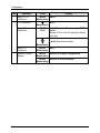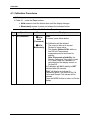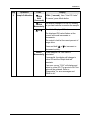
1
DirectLine® DL424/425 Sensor Module
for DL 5000 Dissolved Oxygen Probes
User Manual
70-82-25-113
Rev. 3
3/03
Industrial Measurement and Control
Notices and Trademarks
Copyright 2003 by Honeywell
March 2003
Warranty/Remedy
Honeywell warrants goods of its manufacture as being free of defective materials and faulty
workmanship. Contact your local sales office for warranty information. If warranted goods
are returned to Honeywell during the period of coverage, Honeywell will repair or replace
without charge those items it finds defective. The foregoing is Buyer's sole remedy and is in
lieu of all other warranties, expressed or implied, including those of merchantability
and fitness for a particular purpose. Specifications may change without notice. The
information we supply is believed to be accurate and reliable as of this printing. However, we
assume no responsibility for its use.
While we provide application assistance personally, through our literature and the Honeywell
web site, it is up to the customer to determine the suitability of the product in the application.
CE Conformity
This product is in conformance with the protection requirements of the following European
Council Directives: 89/336/EEC, the Electromagnetic Compatibility Directive and
73/23/EEC, the Low Voltage Directive. Conformance of this product with any other “CE
Mark” Directive(s) shall not be assumed.
ATTENTION
The emission limits of EN 61326 are designed to provide reasonable protection against
harmful interference when this equipment is operated in an industrial environment. Operation
of this equipment in a residential area may cause harmful interference. This equipment
generates, uses and can radiate radio frequency energy and may cause interference to radio
and television reception when the equipment is used closer than 30 m to the antenna(e). In
special cases, when highly susceptible apparatus is used in close proximity, the user may
have to employ additional mitigating measures to further reduce the electromagnetic
emissions of this equipment.
Industrial Measurement and Control
Honeywell
1100 Virginia Drive
Fort Washington, PA 19034
DirectLine is a trademark of Honeywell
Other brands or product names are trademarks of their respective owners
Insert 70-82-10-04 should accompany this document.
ii
DirectLine® DL424/425 Sensor Module User Manual
3/03
About This Document
Abstract
This manual contains all the information that is needed to install, configure, calibrate,
operate, and troubleshoot the DirectLine® Sensor. Insert 70-82-10-04, a quick
reference guide for configuring and calibrating the DL424/425, should accompany
this document.
Contacts
World Wide Web
The following lists Honeywell’s World Wide Web sites that will be of interest to our
customers.
Honeywell Organization
WWW Address (URL)
Corporate
http://www.honeywell.com
Industrial Measurement and Control
http://www.honeywell.com/imc
Telephone
Contact us by telephone at the numbers listed below.
Organization
United States and
Canada
Honeywell
Phone Number
1-800-423-9883
Tech. Support
1-888-423-9883
Q&A Faxback
(TACFACS)
1-800-525-7439
Service
Symbol Definitions
The following table lists any symbols used in this document to denote certain
conditions.
Symbol
Definition
Earth Ground. Functional earth connection. NOTE: This connection shall
be bonded to Protective earth at the source of supply in accordance with
national and local electrical code requirements.
3/03
DirectLine® DL424/425 Sensor Module User Manual
iii
Contents
1. INTRODUCTION .................................................................................................................... 1
1.1
1.2
1.3
1.4
1.5
Overview......................................................................................................................................... 1
Electronics Module ......................................................................................................................... 2
Operator Interface........................................................................................................................... 2
Specifications.................................................................................................................................. 3
Model Selection Guide ................................................................................................................... 4
2. INSTALLATION ..................................................................................................................... 5
2.1
2.2
2.3
2.4
Assembly and Wiring ...................................................................................................................... 5
Integral Mounting ............................................................................................................................ 7
Remote Mounting ........................................................................................................................... 8
Conduit connections ..................................................................................................................... 12
3. CONFIGURATION ............................................................................................................... 13
3.1
3.2
Overview....................................................................................................................................... 13
Configuration Set Up Procedure................................................................................................... 15
4. CALIBRATION..................................................................................................................... 19
4.1
4.2
4.3
New Probe .................................................................................................................................... 19
Calibration Options ....................................................................................................................... 19
Calibration Procedures ................................................................................................................. 20
5. OPERATION ........................................................................................................................ 22
5.1
5.2
5.3
Displays ........................................................................................................................................ 22
Diagnostic Error Messages .......................................................................................................... 24
Unit Reset ..................................................................................................................................... 26
6. SPARE PARTS .................................................................................................................... 27
7. APPENDIX: CE MARK APPLICATIONS ............................................................................ 29
8. SALES AND SERVICE ........................................................................................................ 31
iv
DirectLine® DL424/425 Sensor Module User Manual
3/03
Tables
Table 2-1 Assembly and Wiring Procedure for Field Wiring Connector _____________6
Table 2-2 Integral Mounting Procedure (refer to Figure 2-3) _____________________7
Table 2-3 Remote Mounting Procedure for DL5000 Probes _____________________8
Table 3-1 Dependence of Barometric Pressure on Altitude _____________________13
Table 3-2 Configuration Set Up Procedure _________________________________15
Table 4-1 Calibration Procedure__________________________________________20
Table 5-1 Online Parameter Descriptions __________________________________22
Table 5-2 Display Navigation Procedure ___________________________________23
Table 5-3 Online Diagnostic Errors _______________________________________24
Table 5-4 Factory Default Values ________________________________________26
3/03
DirectLine® DL424/425 Sensor Module User Manual
v
Figures
Figure 1-1 DirectLine® Sensor ___________________________________________1
Figure 1-2 Electronics Module ____________________________________________2
Figure 2-1 Cordset Connection and Wiring ___________________________________5
Figure 2-2 Field Wiring Connector_________________________________________6
Figure 2-3 Integral Mounting _____________________________________________7
Figure 2-4 Remote Mounting _____________________________________________10
Figure 2-5 Remote Mounting Hardware ____________________________________11
vi
DirectLine® DL424/425 Sensor Module User Manual
3/03
3/03
DirectLine® DL424/425 Sensor Module User Manual
vii
Introduction
1. Introduction
1.1 Overview
The DirectLine® Sensor for dissolved oxygen measurement in water consists of a
DL424/425 electronics module connected to a DL5000 DO Probe. The modular
electronics design allows the module to be separated from the probe, so that the
probe can be easily removed or replaced while retaining power to the electronics
module.
The DL424/425 electronics module is contained in a Nema Type 4x sealed
weatherproof corrosion/impact-resistant polysulfone housing. The Module can be
mounted as an integral unit directly connected to the probe or remotely using a
probe with a cable. The sealed plastic housing has plug-in connections for the
DL5000 probe and a 4-20 mA output connection.
Figure 1-1 DirectLine® Sensor
3/03
DirectLine® DL424/425 Sensor Module User Manual
1
Introduction
1.2 Electronics Module
The electronics module is loop-powered by 16-42 Vdc and will modulate its supply
current from 4 mA to 20 mA, depending upon the DO value that is measured by the
probe. The transmitted loop current is compensated for process temperature.
A 4-20 mA output connection is provided via a 6m cordset or a customer supplied
cable used in combination with a field wiring connector.
The DirectLine ® electronic module for dissolved oxygen measurements is available
in two configurations:
ppm (DL424) and ppb (DL425).
Figure 1-2 Electronics Module
1.3 Operator Interface
The DirectLine® Sensor operator interface consists of three pushbuttons and one
4-digit, 7-segment LCD display with 3 decimal points, plus (+), and minus (–) signs.
It is responsible for the display of measured values and configuration of parameter
values.
2
DirectLine® DL424/425 Sensor Module User Manual
3/03
Introduction
1.4 Specifications
General:
Displayed Process
Variable
Displayed
Temperature Range
Operating
Temperature
Storage Temperature
Display Resolution
Output Type
Output Scale
Output Calibration
Power
Calibration Options
Diagnostics
Physical Properties:
Case
Local Display and
Buttons
Field Wiring Cordset
User Termination
Remote Mounting
Dimensions
Weight
Approvals
3/03
DL424: 0-20 ppm dissolved oxygen
DL425: 0-200 ppb dissolved oxygen
2.0 to 60.0 ºC (35.6 to 140ºF)
–20 °C to +60 °C (-4 °F to +140 °F)
–20 °C to +70 °C (-4 °F to +158 °F)
DL424: 0.01 ppm
DL425: 0.1 ppb in the 0-20 ppb range; 1 ppb in the
0-200 ppb range
4-20 mA (2-wire loop powered)
DL424: 0-20ppm
DL425: 0-200ppb
4-20 mA
16-42 Vdc
Maximum Load Resistance:
250 ohms at 16 Vdc
600 ohms at 24 Vdc
1400 ohms at 42 Vdc
Air Cal; Sample Cal
Sensor and electronics
Weatherproof, corrosion-resistant plastic housing
LCD 4-digit, 7-segment
Shielded twisted pair. Length: 6 m (19.7’)
Tinned leads
Pipe, Wall, or DIN Rail
H 123 mm (4.84”) x W 48 mm (1.89”) x D 46 mm (1.81”)
Approximately 142 g (5.0 oz.)
CE Mark - Industrial Applications
UL – General Purpose
CSA – General Purpose
IP66 Enclosure
NEMA Type 4
FM Class1, Div. 1 (I.S.)
FM Class 1, Div. 2 (non-incendive field wiring)
DirectLine® DL424/425 Sensor Module User Manual
3
Introduction
1.5 Model Selection Guide
Instructions
Select the desired key number. The arrow to the right marks the selection available.
Make the desired selections from Tables I through IV using the column below the
proper arrow.
A dot ( ) denotes availability.
Key Number
_____
I
-
_
II
-
_
-
III
_
IV
-
____
Key Number - DirectLine®Sensor Electronics Module
(Specify electrodes/cells/probes separately)
pH
For use with Durafet II, Meredian II & HPW7000 pH electrodes
ORP
For use with ORP electrode.
Conductivity
For use with Contacting Conductivity Cells
DO - PPM
For use with Dissolved Oxygen ppm Probes
For use with Dissolved Oxygen ppb Probes
DO - PPB
Selection
Availability
DL421
DL422
DL423
DL424
DL425
TABLE I - OUTPUT CABLE
Output Cable for None (replacement module or customer supplied output cable)-Note 1
Integral or Remote Cordset - 6m (19.7 ft.) - includes connector and cable - Note 2
Field Wiring Connector only - customer supplies cable only-Note 2
Mounting
D
E
F
TABLE II - SENSOR CABLE/REMOTE CONNECTOR (between electronic module and electrode, sensor or pro
Integral Mounting
No cable or connector required
Remote Mounting Cable 6,096m (20 ft.) of sensor cable - Durafet II Remote Mounting
- Durafet only
15,24m (50 ft.) of sensor cable - Durafet II Remote Mounting
Remote Mounting Connector - Meredian II pH
Remote Mounting
Remote Mounting Connector - Meredian II ORP
Connector (Cable is
Remote Mounting Connector - HPW7000
supplied with sensor or
Remote Mounting Connector - Conductivity
probe)
Remote Mounting Connector - Dissolved Oxygen
0
1
2
3
3
4
5
6
d
e
e
e
d
d
d
d
e
e
e
e
e
TABLE III - REMOTE MOUNTING OPTIONS
Mounting Kit for
Remote Mounting
None Integral unit - mounting not required
2" (5,08 cm) Pipe mtg. bracket, wall mtg, & DIN Rail clip
A
B
TABLE IV - OPTIONS
Tagging
Certificates
None
Linen Customer ID Tag - 3 lines w/22 characters/line
SS Customer ID Tag - 3 lines w/22 character/line
None
Calibration & Conformance
00 _ _
LT _ _
SS _ _
_ _ 00
_ _ CC
Notes:
1 Customer supplies cordset or cable with M12 connecter. Suppliers & P/Ns include:
Cord--set
M12 Field Wiring Connector
Cable
Turck
Phoenix Contact
SAC-3P-5.0-PUR/M12FSSH Stainless
RKV4T-6/S618
SACC-M12FS-4CON-PG7
B8141-0
2-wire twisted shielded pair
2 Recommended cable is 2-wire twisted shielded pair
RESTRICTIONS
Restriction
Letters
d
e
Available Only With
Selection
Table
IIl
A
III
B
Table
Not Available With
Selection
ORDERING INSTRUCTIONS:
1. Part numbers are provided to facilitate Distributor Stock.
2. Orders may be placed either by model selection or by part number.
3. Part numbers are shown within the model selection tables to assist with compatibility information.
4. Orders placed by model selection are systematically protected against incompatibility.
5. Compatibility assessment is the responsibility of the purchaser for orders placed by part number.
6. Items labeled as N/A are not available via the stocking program and must be ordered by model selection.
4
DirectLine® DL424/425 Sensor Module User Manual
3/03
Installation
2. Installation
2.1 Assembly and Wiring
Depending on the customer selected output cable options, the DirectLine can be
wired to an appropriate 16-42 Vdc source using 2 different methods:
1) Cordset. See Figure 2-1.
2) Field wiring connector with customer supplied cable. See page 6.
Refer to Section 7 for wiring for CE Mark applications.
2.1.1 Cordset
Power Supply
Minimum: 16 V @ 250 ohms (max.)
Maximum: 42 V @ 1400 ohms (max.)
_
+
_
Chart Recorder, Load
Controller, etc.
Resistance
(Use 250 ohms +
for 1-5 V signal)
Black (–)
Shield
Wire
(Ground)
Brown (+)
Cordset 6m (19.7’)
*
*Blue wire not used
Electronics
Module
Figure 2-1 Cordset Connection and Wiring
3/03
DirectLine® DL424/425 Sensor Module User Manual
5
Installation
2.1.2 Field Wiring Connector with customer supplied cable
Refer to Figure 2-2. The field wiring connector supports customer supplied cable with an
outer diameter of 4-6mm, 2-wire twisted shielded pair. Required cable is 2-wire twisted
shielded pair with UV resistant outdoor rated outer jacket material. Use of a non-UV
resistant, non-outdoor rated cable will void the NEMA 4 outdoor rating.
Table 2-1 Assembly and Wiring Procedure for Field Wiring Connector
Step
1
2
3
4
5
Procedure
Disassemble field wiring connector
a) Unscrew parts to separate pressure screw, clamp type cage, gasket,
housing and female insert.
Insert customer supplied cable through connector parts
a) Slide pressure screw over skin and tinned customer cable (note
orientation).
b) Slide clamp type cage over cable (note orientation).
c) Slide gasket over cable.
d) Slide housing over cable (note orientation).
Connect wires to pins
Look closely at end of female insert to locate pin numbers. Connect
positive wire to pin 1 and negative wire to pin 4. Remaining wires and
female insert pins 2 and 3 are unused.
Assemble field wiring connector
a) Screw female insert to housing until female insert’s o-ring is
compressed.
b) Slide clamp type cage/gasket into housing.
c) Thread pressure screw into housing until ¼ turn past finger tight.
Connect cable to power supply
Wire the other end of the Output cable to a 16-42 Vdc source as indicated
in Figure 2-1. Note: your wire colors may be different.
To Power Supply
Pressure screw
Clamp-type cage
Gasket
Pos +
Output cable
(Customer supplied)
Neg Housing
Female insert with 4
numbered pins
Figure 2-2 Field Wiring Connector
6
DirectLine® DL424/425 Sensor Module User Manual
3/03
Installation
2.2 Integral Mounting
Table 2-2 Integral Mounting Procedure (refer to Figure 2-3)
Step
Procedure
1
Connect the probe to the process source (using the appropriate mounting
from those supplied for the DL5000).
Make sure that the final position of the installed electronics module
allows the display to be easily viewed by personnel.
2
Apply a thin film of silicon grease on the ID of the electronics module’s
probe mounting cavity.
3
Align the slots on the electronics module with those on the probe and
press down to connect the electronics to the probe.
4
Tighten the locking screw on the bottom rear of the electronics module.
Do not exceed 5 in-lb.
Electronics
Module
Step 2
Step 3
Locking Screw in
Rear of Housing
Step 4
Probe
Step 1
Figure 2-3 Integral Mounting
3/03
DirectLine® DL424/425 Sensor Module User Manual
7
Installation
2.3 Remote Mounting
When the DL424 or DL425 module is specified with Table II = 6, a remote connector
assembly (part number 51500768-005) is supplied loose. The remote cable
connector is used to connect the DL5000 probe cable to the DL424/425 module.
Table 2-3 gives the mounting procedure.
Table 2-3 Remote Mounting Procedure for DL5000 Probes
Step
Procedure (Refer to Figure 2-4 and Figure 2-5)
1
Remove the protective sleeve from the end of the probe cable when
ready to attach to remote connector. Be careful to keep bare fingers
away from coax cable termination.
Turning counterclockwise, remove strain relief/cover combination from
the remote connector assembly.
Loosen and remove compression cap from strain relief fitting. Carefully
push cable end through cap and strain relief fitting so that these parts are
strung back along cable jacket.
Connect cable leads in reverse numerical order as follows:
Terminal 6 = Cathode Silver Pin(coax)
Terminal 5 = Reference (Green)
Terminal 4 = Anode (Red)
Terminal 3 = Temperature Compensation Lead (Yellow)
Terminal 2 = Temperature Compensation Lead (Orange)
Terminal 1 = Pigtail Shield Lead (Black/White)
Earth Ground = Blue
Apply a thin bead of silicone grease to cable jacket in the area of the
compression cap/strain relief. Slide cover along cable and tighten by
hand onto the remote connector assembly.
Slide cap along cable and tighten onto cable jacket with small wrench
until cable cannot slide within strain relief rubber bushing.
Apply a thin film of silicon grease to the ID of electronics module’s remote
mounting cavity.
Plug remote connector assembly into DL424/425 module aligning polarity
tab of module housing and mating groove on connector. (continued)
2
3
4
5
6
7
8
8
DirectLine® DL424/425 Sensor Module User Manual
3/03
Installation
3/03
Step
Procedure (Refer to Figure 2-4 and Figure 2-5)
9
Secure Electronics Module with Wall, Pipe, or DIN Rail Mounting
• Mount bracket with clips facing forward, smaller clip on top and
larger clip on bottom.
Wall:
Use one of three through-holes to secure to wall.
Pipe:
Feed hose clamp through two slots and secure to pipe.
DIN rail: Attach the appropriate DIN rail clip to the mounting bracket:
“U” DIN rail—use metal clip and shorter screw (8 mm)
“G” DIN rail—use gray clip and longer screw (10 mm). Clip
can be rotated for horizontal or vertical DIN rails.
• Push electronics module onto the remote-mounting bracket until it
snaps into position.
DirectLine® DL424/425 Sensor Module User Manual
9
Installation
6
1
5
2
3
Black Protective
Sleeve
(do not remove)
Cathode Silver Pin (Coax)
Reference (Green)
Anode (Red)
Temperature Compensation (Yellow)
Temperature Compensation (Orange)
Pigtail Shield (Black/White)
Earth Ground (Blue)
4
6
5
4
3
2
1
Electronics
Module
Cover
Strain
Relief
Compression
Cap
Remote Wiring Cable
20 Feet
Probe
Remote Electronics for
Module DL5000 Dissolved Oxygen Probes
Figure 2-4 Remote Mounting
10
DirectLine® DL424/425 Sensor Module User Manual
3/03
Installation
Hose Clamp Slot
for Pipe Mounting
(Hose Clamp
included in kit)
Through Hole for
DIN Rail Mounting
Metal clip for
“U” DIN rail mounting
Gray clip for
“G” DIN rail mounting
Mounting Kit
View from End
View from End
Panel
Panel
Terminal Connectors
Barriers, Repeater, Isolators
Front View
Front View
“U” Style DIN Rail
“G” Style DIN Rail
Figure 2-5 Remote Mounting Hardware
3/03
DirectLine® DL424/425 Sensor Module User Manual
11
Installation
2.4 Conduit connections
The DirectLine provides a male ½” NPT thread to accommodate a customer conduit
connection. Use ½” conduit coupling (min. 38.1mm (1.5”) long) on DL conduit
connection to clear cordset connector. Conduit can not be used with field wiring
connector due to size restriction.
Do not exceed 200in-lb. torque when attaching fixed piping.
Use wrench flats provided under the ½” NPT threads to support the DirectLine
during installation.
12
DirectLine® DL424/425 Sensor Module User Manual
3/03
Configuration
3. Configuration
3.1 Overview
Configuration Parameters
Set Up consists of configuring the following functions:
•
Atmospheric Pressure
Compensation:
The solubility of oxygen in water and
DL5000 dissolved oxygen probe signal
directly respond to barometric pressure
and hence pressure compensation is
not required during use. For best
accuracy, the DL424/425 modules
need to know barometric pressure at
the time of probe calibration. If
barometric pressure is known, this
value can be readily entered into the
instrument at this time. This value will
be automatically accessed during air
calibration.
A major contributor to atmospheric
pressure is altitude above or below sea
level. In the absence of a specific
knowledge of barometric pressure
value, use the nominal barometric
pressure value from Table 3-1.
Table 3-1 Dependence of Barometric
Pressure on Altitude
Alt, ft
P, mmHg
Alt, ft
P, mmHg
Sea Level
760
3000
681
200
755
3200
676
400
749
3400
671
600
744
3600
666
800
738
3800
661
1000
733
4000
656
1200
728
4200
652
1400
722
4400
647
1600
717
4600
642
1800
712
4800
637
2000
707
5000
632
2200
701
5200
628
2400
696
5400
623
2600
691
5600
618
2800
686
5800
614
The factory default barometric pressure
value is 760 millimeters of mercury
(mmHg). Any value can be entered in
one step increments from 500 to 800
mm Hg.
•
3/03
Salinity: The solubility of oxygen in salt or brackish waters, containing much
more than 1 part per thousand (ppt) total dissolved solids, is dependent on salt
concentration. The DL424 instrument accepts the total dissolved salt
concentration in ppt and performs necessary calculations to obtain the correct
dissolved oxygen concentration over salt concentration and sample temperature.
The DL 424 factory default value is 0 ppt but valid readings can range from 0 - 40
ppt and can be entered by the user in 0.1ppt increments.
The DL425 is intended for high purity water applications; salinity compensation is
not employed here.
DirectLine® DL424/425 Sensor Module User Manual
13
Configuration
•
•
•
•
•
•
14
Probe Bias Voltage – This feature is not applicable to typical DO applications
and is generally performed as a result of a “berr” message.
The probe bias voltage value determines the voltage applied to the DO probe's
cathode, relative to the reference electrode, to drive the reduction of oxygen to
water at the cathode and thereby induce a current which is directly proportional
to the oxygen consumed. A proper probe bias voltage allows for the complete
reduction of all oxygen at the cathode, without regard for small changes in the
voltage characteristics of the probe. This parameter can be read, scanned or
reset to the factory default value.
In the DL425, the automated probe bias voltage option is only allowed when the
probe has been removed from the process.
In the DL424, in applications containing carbon dioxide, it may be undesirable to
remove the probe from the process. Therefore in the DL424 the probe bias
voltage can be edited directly in the process.
Noise Suppression Frequency Selection – Selection of 50 Hz or 60 Hz.
Defaults to 60 Hz at unit reset.
Output Configuration and Calibration – Selection of Output Configuration
functions: 0% Calibration, 100% Calibration, 0% Output Range Value, 100%
Output Range Value.
Table 3-2 provides steps and entry information for the complete configuration
sequence.
DirectLine® DL424/425 Sensor Module User Manual
3/03
Configuration
3.2 Configuration Set Up Procedure
ATTENTION:
In Table 3-2, under the Press column:
• Hold means to hold the button down until the display changes.
• Momentarily means to press and release the indicated button.
From the Online DO display, follow this procedure.
ATTENTION:
If no key is pressed for 60 seconds, the display will abort the entry mode and
default to Online Display.
Table 3-2 Configuration Set Up Procedure
Step
Operation
Press
1
Enter Atmospheric
Pressure
Compensation
MODE
Hold
AtPr (for 1 second), then
Value of Atmospheric Pressure Value in
mm Hg
Edit Atmospheric
Pressure Value
MODE
Hold
Flashing Display – You are now in EDIT
mode
(Value of Current Atmospheric Pressure
Compensation )
2
Select a new value
Enter a value from 500 to 800 mm Hg (760
or
Momentarily mm HG default)
Save the value
Saves the new Atmospheric Pressure
MODE
Momentarily Compensation value for use at the next Air
Calibration.
Enter Salinity
Compensation
(ppm units only)
SALn (for 1 second), then
MODE
Momentarily Value of current Salinity Compensation in
Parts per Thousand
Edit Salinity
Compensation
3/03
Display
MODE
Hold
Flashing Display – You are now in EDIT
mode
(Value of current Salinity Compensation)
Select a new value
Enter a value from 0 (default) to 40 ppt
or
Momentarily
Save the value
Saves the new Salinity Compensation
MODE
Momentarily Value
DirectLine® DL424/425 Sensor Module User Manual
15
Configuration
Step
Operation
Press
3
Enter Probe Bias
Voltage (not
needed for typical
applications – do
not use unless
“berr” is indicated
or there is a
historical
precedence for
operating at a
different setting
b IAS (for 1 second), then
MODE
Momentarily Value of current Probe Bias Voltage in
Volts
Go to 3a, 3b, or 3c
Remove the probe from the process
prior to 3a - Probe Bias Calibration.
3a.
Automated Probe
Bias Voltage
Flashing Display – bIAS
Bias Scan begins and the display flashes
Hold
(3 seconds) until the scan is complete.
An optimal Probe Bias value is determined
and displayed after the scan is complete
(up to 2 minutes).
Note: Pressing the MODE button
momentarily during scanning process
aborts the scan and the prior Probe Bias
value is retained.
3b.
Reset the Probe
Bias Value
4
Display will show "0.55".
Probe Bias Voltage is reset.
3c.
Manual input for
Probe Bias
Display will flash the current probe bias
MODE
Hold
value.
(3 seconds)
Select a new value
Use up/down arrows to edit Probe Bias
or
Momentarily
Save the Probe
Bias Voltage
Saves the Probe Bias Voltage
MODE
Momentarily
Enter Noise
Suppression
Frequency
nSUP (for 1 second) then,
MODE
Momentarily (Noise Suppression Frequency Selection)
Edit Noise
Suppression
Frequency
Select desired
Frequency
16
Hold
(10
seconds)
Display
MODE
Hold
Flashing Display – You are now in EDIT
mode
(Value of current Frequency selection)
to select 50 Hz or 60 Hz (default)
Momentarily
DirectLine® DL424/425 Sensor Module User Manual
3/03
Configuration
Step
5
Operation
Press
Display
Save the Noise
Suppression
Frequency
Saves the selection for frequency
MODE
Momentarily
Enter Output
Configuration
MODE
OutC Enter Output Calibration
Momentarily
100% Range Value
Selection
rnGH (for 1 second) then,
(Value
of current 100 % Range Value
Momentarily
Selection)
Edit 100% Range
Value Selection
Select desired
100% DO Range
MODE
Hold
Flashing Display – You are now in EDIT
mode
(Value of current 100 % selection)
Selected 100% DO Value
Momentarily Range:
DL424 = 0 to 20 ppm
DL425 = 0 to 200 ppb
Save the New 100%
(New Value)
MODE
Range Value
Momentarily
6
0 % Range Value
Selection
Edit 0 % Range
Value Selection
7
rnGL(for 1 second) then,
(value
of current 0% Range Value
Momentarily
Selection)
MODE
Hold
Flashing Display – You are now in EDIT
mode
(value of current 0 % selection)
Select 0 % DO
Value
Selected 0 % DO Value
Momentarily Range:
DL424 = 0 to 20 ppm
DL425 = 0 to 200 ppb
Save the New 0 %
Range Value
(New Value)
MODE
Momentarily
100 % Calibration
AdJH
Momentarily
Adjust 100 %
Calibration
MODE
Hold
AdJH (flashes) – You are now in EDIT
mode
Range: 19.60 to 20.40 mA typically
(default 20.00 mA)
+AdJH (increments value)
−AdJH (decrements value)
Momentarily
3/03
DirectLine® DL424/425 Sensor Module User Manual
17
Configuration
Step
Operation
Save 100 %
Calibration
8
Press
Display
MODE
AdJH
Momentarily
0 % Calibration
AdJL
Momentarily
Adjust 0 %
Calibration
MODE
Hold
AdJL (flashes) – You are now in EDIT
mode
Range: 3.80 to 4.40 mA typically (default
4.00 mA)
+AdJL (increments value)
−AdJL (decrements value)
Momentarily
9
Save 0 %
Calibration
MODE
AdJL
Momentarily
Return to Online
Display
MODE
Returns to Output Configuration
Momentarily
MODE
Returns to Online Display
Momentarily
18
DirectLine® DL424/425 Sensor Module User Manual
3/03
Calibration
4. Calibration
4.1 New Probe
New Probe Reset Option
Upon system power up or probe connection, the new probe reset option is
displayed. The nPrb message is available for 2 minutes and can be selected by
pressing the up arrow until the display changes to the unit type and DO value. The
user must select this option when inserting a new probe. The Air and Sample
calibration values are set to the factory defaults and the probe current is measured
and saved as a diagnostic aid. An Air calibration is recommended after a new probe
is installed.
If a new probe is not installed, the operator can return to on-line measurement by
waiting for the 2 minute timeout or by pressing the Mode button.
4.2 Calibration Options
Introduction
Whether the probe is connected for the first time, replaced or just disconnected and
then reconnected, a reconditioning period is needed before the probe can make an
accurate measurement. (See DL5000 Probe Manual 70-82-25-114)
Options
Two Calibration options are available: Air and Sample Calibration.
These parameters can only be selected when online DO is displayed.
• Air Calibration - is done with the probe removed from the process. This is the
recommended method of calibration and should be completed unless the
process set-up prohibits removing the probe. This is recommended prior to
installation as it saves system parameters that are used in optimizing error
diagnostics.
If the probe has just been removed from a sample low in dissolved oxygen, it
takes longer to complete a calibration than that of a probe that is already near
ambient conditions (sample high in dissolved oxygen).
• Sample Calibration - Sample calibration allows a calibration based on a known
dissolved oxygen concentration where a DO value may be entered that is based
on a reference measurement. Sample calibration is usually executed by leaving
the probe in the measured sample and adjusting the DirectLine® to agree with
the sample dissolved oxygen measured with a properly calibrated portable
dissolved oxygen meter whose probe is held very close to the process probe.
For those situations where sample calibration is preferred, it is recommended
that an Air Calibration be performed before the probe is put into service. It is also
good practice to Air Calibrate the probe once every 2 - 4 months of service.
3/03
DirectLine® DL424/425 Sensor Module User Manual
19
Calibration
4.3 Calibration Procedures
ATTENTION:
In Table 4-1, under the Press column:
• Hold means to hold the button down until the display changes.
• Momentarily means to press and release the indicated button.
Table 4-1 Calibration Procedure
Step
1
20
Operation
Air Calibration
Press
Display
ACAL
ACal
To cancel, press Mode button.
Hold
(3 seconds)
Air Calibration will be initiated.
ACal
• The output is held at its current
Momentarily
Percent-of-range value
• The display flashes ACAL while online DO and Temperature
measurements are monitored for
stability.
After 20 seconds of stability, the
Sample Calibration Trim value is reset
to 1.0 and a new Air Calibration is
calculated and the display returns to
On-line DO.
Air Calibration will fail if stability is NOT
achieved after 30 seconds
"FAIL" will display to indicate Air
Calibration failure. The previous Air Cal
Factor and Sample Trim values will be
retained.
Press the MODE button to return to On-line
display.
DirectLine® DL424/425 Sensor Module User Manual
3/03
Calibration
Step
Operation
Press
2
Sample Calibration
Display
SCAL (1 second), then "Live DO Value"
SCal
Hold
To cancel, press Mode button
(3 seconds)
The display changes to a live DO reading,
SCal
Momentarily so you can continue to monitor the sample.
or
To edit the Displayed DO value.
The displayed DO value flashes at the
current value and increments or
decrements.
The output is held at its current percent of
range value.
or
Press and hold
decrement quickly.
to increment or
A new Sample Cal Trim value is
MODE
Momentarily calculated.
If successful, the display will change to
online DO and the Output hold will
terminate.
If an error occurs, "FAIL" will display and
return to online DO. The previous Cal Trim
value will be retained. Refer to
"Diagnostics" for error messages and
"What to do".
3/03
DirectLine® DL424/425 Sensor Module User Manual
21
Operation
5. Operation
5.1 Displays
Overview
The DirectLine® DL424/425 displays the On-line DO Concentration value and the Online Temperature. The table below describes these parameters.
Table 5-1 Online Parameter Descriptions
Parameter
Description
Online DO
D424 Range: ppm = 0.00 to 20.00
D425 Range:ppb = 0 to 200
Online
Temperature
Measured temperature expressed with fixed tenths decimal
precision.
Temperature displayed in °C or °F
Range: 2.0 to 60.0 °C
35.6 to 140.0 °F
The default display and home position is the Online DO display. It appears when:
• The unit is powered up after the nPrb option is selected
• No button presses for 60 seconds
• The Mode button has been pressed during Air or Sample calibration
• The Mode button has been pressed momentarily during a configuration edit
The DO measurement and display is updated at a rate of 500 ms.
In the DL425, when the DO value is outside the 200ppb range, the live DO value will
alternately flash ppm and the current reading. The output will be in burnout as the
reading is outside the operating range.
22
DirectLine® DL424/425 Sensor Module User Manual
3/03
Operation
ATTENTION:
In Table 5-2, under the Press column:
• Momentarily means to press and release the indicated button.
Table 5-2 Display Navigation Procedure
Step
Operation
View Online DO
1
Concentration value
View Online
2
Temperature
2A Toggle Online
Temperature display
units
Return to home
3
position
3/03
Press
Display
MODE
(measured DO)
Momentarily
MODE
(measured temperature in °C or °F)
Proceed to step 2A or step 3.
Momentarily
(measured temperature in °C or °F)
or
Proceed to step 3.
Momentarily
MODE
(measured DO)
Momentarily
DirectLine® DL424/425 Sensor Module User Manual
23
Operation
5.2 Diagnostic Error Messages
When a diagnostic error or status condition occurs, the Online Display alternates
between measured DO and a text message.
Table 5-3 Online Diagnostic Errors
What you see
Cause of Error
What to do
CnFG
Configuration or Calibration data is
defective.
Reset unit or cycle power.
Second occurrence will
show FALt.
FALt
Unit electronics are defective.
Replace electronics module.
These errors may occur when on-line DO Concentration or on-line Temperature is
displayed.
dOHI
Measured DO is > 20 ppm/200 ppb
Bring process within limits
PrbE
Probe is defective, wrong type, or not
connected.
Probe current is excessive with probe
voltage near 0 volts
Forces the output to burnout level (greater
than 22 mA).
Check for an electrical short
between the anode and the
cathode.
Check the reference
electrode connection.
When the source of the
error is removed, the error
will clear and the output will
return to normal operation.
T HI
Measured temperature is > 60 °C
Bring process within limits
T LO
Measured temperature is < 2.0 °C
Bring process within limits
BErr
•
For a new probe only –
Select nprb and perform an
air calibration.
•
Probe Bias Error:
Probe current has exceeded expected
probe current in air by 33% and the
bias voltage is automatically reduced.
If the excessive current condition
continues then the PrbE error is
generated. If excessive current is not
present then the bErr remains
Application related shift in probe bias
voltage.
For a probe in-use Remove the probe from
process and do a probe
bias calibration. In ppm
applications in processes
containing CO2, the probe
may be left in the process
and the probe bias can be
manually adjusted.
Remove the probe from the
process and do an Air
Calibration.
24
DirectLine® DL424/425 Sensor Module User Manual
3/03
Operation
What you see
FAIL
Cause of Error
Verify that Probe has been
During air calibration the probe current removed from the process.
is too low or if the probe readings are
unstable
Verify that probe has
reached equilibrium with the
There is excessive probe current
during a Probe bias voltage calibration process
This error can occur if
•
•
An air calibration can not be completed
and the previous air calibration value is
retained.
3/03
What to do
Press Mode to return to
online display.
DirectLine® DL424/425 Sensor Module User Manual
25
Operation
5.3 Unit Reset
Overview
Unit Reset initializes all of the DirectLine® Sensor’s calibration and configuration
data to factory default values. The Air calibration value is also reset to the factory
default.
Procedure
• From the Online DO display, press and hold the
and buttons
simultaneously until “rSEt” appears on the display (minimum of 10 seconds).
• “rSEt” will remain on the display for about 8 seconds followed by the firmware
version, the DO Measurement units (ppm or ppb) and the online DO
Concentration value. The unit then returns to the Online DO display.
Table 5-4 Factory Default Values
Data
Default Values
Air/Sample calibration
Factory default
Atmospheric Pressure
760 mm Hg
Salinity
0 ppt
Probe Bias Voltage
26
0.55 Volts
Noise Suppression Frequency Selection
60 Hz
Output Configuration – 0 % Range Value
4.00mA
Output Configuration – 100 % Range Value
20.00mA
Output Configuration – 0 % Calibration
0.00 ppm / 0.0 ppb
Output Configuration – 100 % Calibration
20.00 ppm/200 ppb
DirectLine® DL424/425 Sensor Module User Manual
3/03
Spare Parts
6. Spare Parts
Part Number
Description
51452682-004
51452682-005
DirectLine® DL424 Sensor Module (Replacement Module)
DirectLine® DL425 Sensor Module (Replacement Module)
51452683-001
6m Cordset
51452684-001
Field Wiring connector supports customer supplied cable (4-6mm
OD)
51452655-001
Remote Mounting Kit for Wall, Pipe, or DIN Mounting
51500768-005
Remote Probe Cable Connector Assembly— Includes O-rings
and strain relief
51451371-003
Cable Strain Relief
51198302-006
Internal O-ring for Remote Probe Cable Connector
51452706-001
Locking screw (locks sensor module to probe electrode)
Cordset
The cordset connection is an M12 female type that can be purchased directly from
Honeywell or from multiple vendors including:
Turck Industries
Part Number RKV4T-6/S618 for a 6 m cordset with a stainless coupling nut
Part Number RK4T-6/S618 for a 6 m cordset with a nickel plated coupling nut
Phoenix Contact
Part Number SAC-3P-5.0-PUR/M12FSSH Stainless for a 5m cordset with a stainless coupling nut
Part Number SAC-3P-5.0-PUR/M12FSSH for a 5m cordset with a nickel plated coupling nut
Field Wiring connector
The Field Wiring Connector is an all-plastic screw terminal M12 female type that can
be purchased directly from Honeywell or from multiple vendors including:
Turck Industries
Part Number B8141-0 for a M12 field wiring connector that accommodates customer supplied
cable.
Phoenix Contact
Part Number SACC-M12FS-4CON-PG7 for a M12 field wiring connector that accommodates
customer supplied cable.
3/03
DirectLine® DL424/425 Sensor Module User Manual
27
Spare Parts
28
DirectLine® DL424/425 Sensor Module User Manual
3/03
Appendix
7. Appendix: CE Mark Applications
CE Conformity (Europe): This product is in conformity with the protection
requirements of 89/336/EEC, the EMC Directive. Conformity of this product with any
other “CE Mark” Directive(s) shall not be assumed.
Deviation from the installation conditions specified in this manual, and the following
special conditions, may invalidate this product’s conformity with the EMC Directive.
CE Conformity Special Conditions (Europe): Shielded twisted pair cables are
required for I/O interface circuits.
29
DirectLine® DL423 Sensor Module User Manual
3/03
30
DirectLine® DL424/425 Sensor Module User Manual
3/03
8. Sales and Service
For application assistance, current specifications, pricing, or name of the nearest Authorized Distributor,
contact one of the offices below.
ARGENTINA
HONEYWELL S.A.I.C.
BELGRANO 1156
BUENOS AIRES
ARGENTINA
Tel. : 54 1 383 9290
ASIA PACIFIC
HONEYWELL ASIA
PACIFIC Inc.
Room 3213-3225
Sun Kung Kai Centre
N° 30 Harbour Road
WANCHAI
HONG KONG
Tel. : 852 829 82 98
AUSTRALIA
HONEYWELL LIMITED
5 Thomas Holt Drive
North Ryde Sydney
NSW AUSTRALIA 2113
Tel. : 61 2 353 7000
AUSTRIA
HONEYWELL AUSTRIA
G.m.b.H.
Handelskai 388
A1020 VIENNA
AUSTRIA
Tel. : 43 1 727 800
BELGIUM
HONEYWELL S.A.
3 Avenue de Bourget
B-1140 BRUSSELS
BELGIUM
Tel. : 32 2 728 27 11
BRAZIL
HONEYWELL DO
BRAZIL
AND CIA
Rua Jose Alves Da
Chunha
Lima 172
BUTANTA
05360.050 SAO PAULO
SP
BRAZIL
Tel. : 55 11 819 3755
BULGARIA
HONEYWELL EOOD
14, Iskarsko Chausse
POB 79
BG- 1592 Sofia
BULGARIA
Tel : 359-791512/
794027/ 792198
3/03
CANADA
HONEYWELL LIMITED
THE HONEYWELL
CENTRE
300 Yorkland Blvd.
NORTH YORK,
ONTARIO
M2J 1S1
CANADA
Tel.: 800 461 0013
Fax:: 416 502 5001
CZECH
REPUBLIC
HONEYWELL, Spol.s.r.o.
Budejovicka 1
140 21 Prague 4
Czech Republic
Tel. : 42 2 6112 3434
DENMARK
HONEYWELL A/S
Automatikvej 1
DK 2860 Soeborg
DENMARK
Tel. : 45 39 55 56 58
FINLAND
HONEYWELL OY
Ruukintie 8
FIN-02320 ESPOO 32
FINLAND
Tel. : 358 0 3480101
FRANCE
HONEYWELL S.A.
Bâtiment « le Mercury »
Parc Technologique de St
Aubin
Route de l’Orme
(CD 128)
91190 SAINT-AUBIN
FRANCE
Tel. from France:
01 60 19 80 00
From other countries:
33 1 60 19 80 00
GERMANY
HONEYWELL AG
Kaiserleistrasse 39
D-63067 OFFENBACH
GERMANY
Tel. : 49 69 80 64444
HUNGARY
HONEYWELL Kft
Gogol u 13
H-1133 BUDAPEST
HUNGARY
Tel. : 36 1 451 43 00
ICELAND
HONEYWELL
Hataekni .hf
Armuli 26
PO Box 8336
128 reykjavik
Iceland
Tel : 354 588 5000
ITALY
HONEYWELL S.p.A.
Via P. Gobetti, 2/b
20063 Cernusco Sul
Naviglio
ITALY
Tel. : 39 02 92146 1
MEXICO
HONEYWELL S.A. DE
CV
AV. CONSTITUYENTES
900
COL. LOMAS ALTAS
11950 MEXICO CITY
MEXICO
Tel : 52 5 259 1966
THE NETHERLANDS
HONEYWELL BV
Laaderhoogtweg 18
1101 EA AMSTERDAM
ZO
THE NETHERLANDS
Tel : 31 20 56 56 911
NORWAY
HONEYWELL A/S
Askerveien 61
PO Box 263
N-1371 ASKER
NORWAY
Tel. : 47 66 76 20 00
POLAND
HONEYWELL Sp.z.o.o
UI Domainewksa 41
02-672 WARSAW
POLAND
Tel. : 48 22 606 09 00
PORTUGAL
HONEYWELL
PORTUGAL LDA
Edificio Suecia II
Av. do Forte nr 3 - Piso 3
2795 CARNAXIDE
PORTUGAL
Tel. : 351 1 424 50 00
REPUBLIC OF IRELAND
HONEYWELL
Unit 1
Robinhood Business
Park
Robinhood Road
DUBLIN 22
Republic of Ireland
Tel. : 353 1 4565944
REPUBLIC OF
SINGAPORE
HONEYWELL PTE LTD
BLOCK 750E CHAI
CHEE ROAD
06-01 CHAI CHEE IND.
PARK
1646 SINGAPORE
REP. OF SINGAPORE
Tel. : 65 2490 100
REPUBLIC OF SOUTH
AFRICA
HONEYWELL
Southern Africa
PO BOX 138
Milnerton 7435
REPUBLIC OF SOUTH
AFRICA
Tel. : 27 11 805 12 01
ROMANIA
HONEYWELL Office
Bucharest
147 Aurel Vlaicu Str.,
Sc.Z.,
Apt 61/62
R-72921 Bucharest
ROMANIA
Tel : 40-1 211 00 76/
211 79
RUSSIA
HONEYWELL INC
4 th Floor Administrative
Builiding of AO "Luzhniki"
Management
24 Luzhniki
119048 Moscow
RUSSIA
Tel : 7 095 796 98 00/01
SLOVAKIA
HONEYWELL Ltd
Mlynske nivy 73
PO Box 75
820 07 BRATISLAVA 27
SLOVAKIA
Tel. : 421 7 52 47 400/
425
TURKEY
HONEYWELL
Otomasyon ve Kontrol
Sistemlen San ve Tic
A.S.
(Honeywell Turkey A.S.)
Emirhan Cad No 144
Barbaros Plaza C. Blok
Kat 18
Dikilitas 80700 Istanbul
TURKEY
Tel : 90-212 258 18 30
UNITED KINGDOM
HONEYWELL
Unit 1,2 &4 Zodiac House
Calleva Park
Aldermaston
Berkshire RG7 8HW
UNITED KINGDOM
Tel : 44 118 906 2600
U.S.A.
HONEYWELL INC.
INDUSTRIAL PROCESS
CONTROLS
1100 VIRGINIA DRIVE
PA 19034-3260
FT. WASHINGTON
U.S.A.
Tel. : 1-800-343-0228
VENEZUELA
HONEYWELL CA
APARTADO 61314
1060 CARACAS
VENEZUELA
Tel. : 58 2 239 0211
SPAIN
HONEYWELL S.A
Factory
Josefa Valcarcel, 24
28027 MADRID
SPAIN
Tel. : 34 91 31 3 61 00
SWEDEN
HONEYWELL A.B.
S-127 86 Skarholmen
STOCKHOLM
SWEDEN
Tel. : 46 8 775 55 00
SWITZERLAND
HONEYWELL A.G.
Hertistrasse 2
8304 WALLISELLEN
SWITZERLAND
Tel. : 41 1 831 02 71
DirectLine® DL424/425 Sensor Module User Manual
31
32
DirectLine® DL424/425 Sensor Module User Manual
3/03
Industrial Measurement and Control
Honeywell
1100 Virginia Drive
Fort Washington, PA 19034
70-82-25-113 0303 Printed in USA
www.honeywell.com/imc