1
9782 Series pH/ORP
Analyzer/Controller
Operator’s Manual
70-82-25-73
Rev 5
3/00
Sensing and Control
Copyright, Notices, and Trademarks
Printed in U.S.A. – © Copyright 2000 by Honeywell
Revision 5 – March 30, 2000
WARRANTY/REMEDY
Honeywell warrants goods of its manufacture as being free of defective materials and faulty
workmanship. Contact your local sales office for warranty information. If warranted goods are
returned to Honeywell during the period of coverage, Honeywell will repair or replace without
charge those items it finds defective. The foregoing is Buyer’s sole remedy and is in lieu of all
other warranties, expressed or implied, including those of merchantability and fitness for a
particular purpose. Specifications may change without notice. The information we supply is
believed to be accurate and reliable as of this printing. However, we assume no responsibility for
its use.
While we provide application assistance personally, through our literature and the Honeywell web
site, it is up to the customer to determine the suitability of the product in the application.
CE CONFORMITY
This product is in conformance with the protection requirements of the following European Council
Directives: 89/336/EEC, the Electromagnetic Compatibility Directive and 73/23/EEC, the Low Voltage
Directive. Conformance of this product with any other “CE Mark” Directive(s) shall not be assumed.
ATTENTION
The emission limits of EN 50081-2 are designed to provide reasonable protection against harmful
interference when this equipment is operated in an industrial environment. Operation of this equipment in a
residential area may cause harmful interference. This equipment generates, uses and can radiate radio
frequency energy and may cause interference to radio and television reception when the equipment is used
closer than 30 m to the antenna(e). In special cases, when highly susceptible apparatus is used in close
proximity, the user may have to employ additional mitigating measures to further reduce the
electromagnetic emissions of this equipment.
Sensing and Control
Honeywell
11 West Spring Street
Freeport, Illinois 61032
AutoCal, AutoClean, DualCal, and Durafet are trademarks of Honeywell.
Noryl is a trademark of GE Company.
Other brand or product names are trademarks of their respective owners.
ii
9782 Series pH/ORP Analyzer/Controller - Operator’s Manual
3/00
About This Document
Abstract
This manual contains instructions for installation and operation of the 9782 Series pH/ORP
Analyzer/Controller.
Contacts
World Wide Web
The following lists Honeywell’s World Wide Web sites that will be of interest to our customers.
Honeywell Organization
WWW Address (URL)
Corporate
http://www.honeywell.com
Sensing and Control
http://www.honeywell.com/sensing
International
http://www.honeywell.com/Business/global.asp
Telephone
Contact us by telephone at the numbers listed below.
Organization
United States and Canada
Honeywell
Phone Number
1-800-423-9883
1-888-423-9883
1-800-525-7439
Asia Pacific
Honeywell Asia Pacific
Hong Kong
(852) 2829-8298
Europe
Honeywell PACE, Brussels, Belgium
[32-2] 728-2111
Latin America
Honeywell, Sunrise, Florida U.S.A.
(854) 845-2600
3/00
9782 Series pH/ORP Analyzer/Controller - Operator’s Manual
Tech. Support
Q&A Faxback
(TACFACS)
Service
iii
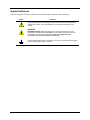
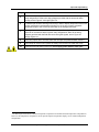
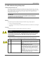
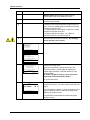
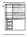
Symbol Definitions
The following table lists those symbols used in this document to denote certain conditions.
Symbol
Definition
This CAUTION symbol on the equipment refers the user to the Product Manual for
additional information. This symbol appears next to required information in the
manual.
WARNING
PERSONAL INJURY: Risk of electrical shock. This symbol warns the user of a
potential shock hazard where HAZARDOUS LIVE voltages greater than 30 Vrms,
42.4 Vpeak, or 60 Vdc may be accessible. Failure to comply with these
instructions could result in death or serious injury.
Protective Earth (PE) terminal. Provided for connection of the protective earth (green
or green/yellow) supply system conductor.
iv
9782 Series pH/ORP Analyzer/Controller - Operator’s Manual
3/00
Contents
1.
INTRODUCTION ....................................................................................................1
1.1
Description ................................................................................................................................1
1.2
Features......................................................................................................................................2
1.3
Operating the Analyzer/Controller ............................................................................................4
1.4
Menu Hierarchy.........................................................................................................................6
1.5
Planning.....................................................................................................................................8
1.5.1 Overview.......................................................................................................................8
1.5.2 Using Relays .................................................................................................................8
1.5.3 Deciding on a Control Strategy ....................................................................................9
1.6
Overview of Installation and Setup Tasks...............................................................................11
2.
SPECIFICATIONS AND MODEL NUMBER.........................................................13
2.1
Specifications ..........................................................................................................................13
2.2
Model Number Breakdown .....................................................................................................16
3.
UNPACKING, PREPARATION, AND MOUNTING ..............................................19
3.1
Overview .................................................................................................................................19
3.2
Unpacking and Preparing ........................................................................................................20
3.3
Installing Optional Internal Preamplifier.................................................................................21
3.4
Mounting .................................................................................................................................22
4.
POWER WIRING ..................................................................................................27
4.1
Overview .................................................................................................................................27
4.2
General Wiring Practices.........................................................................................................28
4.3
Power Wiring Considerations .................................................................................................29
4.4
Installing Power Wiring ..........................................................................................................30
5.
I/O SETUP AND SYSTEM CONFIGURATION.....................................................33
5.1
Overview .................................................................................................................................33
5.2
I/O Setup and Configuration Tasks .........................................................................................34
5.3
Performing I/O Setup...............................................................................................................39
5.4
Configuring Current Adjusting Type (CAT) Control and/or Retransmission of Process
Variables ..................................................................................................................................43
5.5
Configuring On/Off, Duration Adjusting Type (DAT), or Pulse Frequency Type (PFT)
Control .....................................................................................................................................46
3/00
9782 Series pH/ORP Analyzer/Controller - Operator’s Manual
v
5.6
Configuring Alarms.................................................................................................................50
5.7
Setting the Clock .....................................................................................................................51
5.8
Configuring AutoCal and AutoClean......................................................................................52
6.
INPUT AND OUTPUT WIRING ............................................................................61
6.1
Overview .................................................................................................................................61
6.2
General Wiring Practices.........................................................................................................62
6.3
Wiring Analog Inputs and Outputs..........................................................................................64
6.3.1 Installation ..................................................................................................................64
6.3.2 Special Information for DualCAT ..............................................................................66
6.4
Wiring Relays ..........................................................................................................................72
6.4.1 Installation ..................................................................................................................72
6.4.2 Special Information for DualCal ................................................................................74
6.4.3 Disconnecting RC Arc Suppression Circuits..............................................................76
7.
AUTOCLEAN AND AUTOCAL THEORY AND PIPING .......................................77
7.1
Overview .................................................................................................................................77
7.2
AutoClean Sequence and Piping .............................................................................................78
7.3
AutoCal Sequence and Piping .................................................................................................80
8.
MANUAL CALIBRATION .....................................................................................83
8.1
Overview .................................................................................................................................83
8.2
Buffering Method of Calibrating pH Electrodes.....................................................................85
8.3
Grab Sample Method of Calibrating pH Electrodes ...............................................................87
8.4
ORP Calibration Using Reference Solution............................................................................89
8.5
ORP Calibration Using Voltage Input.....................................................................................91
8.6
Calibrating pH Electrodes Using Automatic Buffer Recognition...........................................94
8.6.1 Introduction.................................................................................................................94
8.6.2 Choosing Neutral and Alkaline Buffers .....................................................................95
8.6.3 Manual Calibration Using Automatic Buffer Recognition.........................................96
8.7
Viewing Zero Offset and Percent Theoretical Slope ..............................................................99
8.8
Recommendations for Successful Measurement and Calibration.........................................100
9.
vi
DIAGNOSTICS AND MESSAGES .....................................................................101
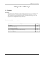
9.1
Overview ...............................................................................................................................101
9.2
System Status Message..........................................................................................................102
9.3
Process Alarm Messages .......................................................................................................103
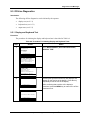
9.4
On-Line Diagnostics and System Error Messages ................................................................104
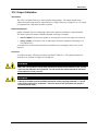
9.5
Off-Line Diagnostics .............................................................................................................105
9.5.1 Display and Keyboard Test ......................................................................................105
9.5.2 Output Tests..............................................................................................................107
9782 Series pH/ORP Analyzer/Controller - Operator’s Manual
3/00
10.
MAINTENANCE..................................................................................................109
10.1
Overview ...............................................................................................................................109
10.2
Output Calibration.................................................................................................................111
10.3
Restoring Factory Calibration Settings .................................................................................114
10.4
Specifying a Tagname or Other Display String.....................................................................115
10.5
Viewing Product Information and Changing Model Number Stored in Memory.................116
10.6
Adjusting the Screen Contrast...............................................................................................118
10.7
Entering a Password for Security ..........................................................................................119
10.8
Resetting All Configuration and Calibration Values to Factory Settings .............................120
10.9
Switching Between Electrodes with DualCal .......................................................................121
10.10
Determining and Entering a Solution Temperature Coefficient ...........................................122
10.10.1 Introduction ...........................................................................................................122
10.10.2 Determining Solution Temperature Coefficient....................................................122
10.10.3 Entering Solution Temperature Coefficient ..........................................................124
10.11
Turning on Temperature Display (Durafet Electrodes without Cap Adapter Only)............125
10.12
Specifying Relay Activation..................................................................................................126
10.13
Replacing the Fuse ................................................................................................................127
11.
ACCESSORIES AND REPLACEMENT PARTS LIST .......................................129
11.1
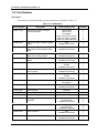
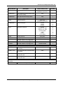
Overview ...............................................................................................................................129
11.2
Part Numbers .........................................................................................................................130
A.
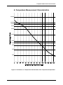
TEMPERATURE MEASUREMENT CHARACTERISTICS .................................133
B.
CYANIDE WASTE TREATMENT .......................................................................135
B.1
Introduction ...........................................................................................................................135
B.2
First Stage of Cyanide Destruction .......................................................................................136
B.3
Second Stage of Cyanide Destruction ...................................................................................137
B.4
Batch Treatment ....................................................................................................................138
B.5
ORP Potential a Measure of Status of Reaction....................................................................138
C.
CHROME WASTE TREATMENT .......................................................................139
C.1
Use of Chromates ..................................................................................................................139
C.2
First Stage of Chrome Removal ............................................................................................140
C.3
Second Stage of Chrome Removal ........................................................................................141
C.4
Batch Treatment ....................................................................................................................142
C.5
ORP Potential a Measure of Status .......................................................................................142
D.
3/00
SIMULTANEOUS PH AND ORP MEASUREMENT ...........................................143
9782 Series pH/ORP Analyzer/Controller - Operator’s Manual
vii
E.
PROPORTIONAL CONTROL TUNING..............................................................145
E.1
F.
MICROPROCESSOR BOARD SWITCH SETTINGS .........................................147
F.1
viii
Overview ...............................................................................................................................145
Overview ...............................................................................................................................147
9782 Series pH/ORP Analyzer/Controller - Operator’s Manual
3/00
Tables
Table 1-1 Key Functions ..............................................................................................................................4
Table 1-2 9782 pH Analyzer/Controller Menu Hierarchy ...........................................................................6
Table 1-3 Overview of Analyzer/Controller Installation Tasks.................................................................11
Table 3-1 Procedure for Unpacking and Preparing the 9782.....................................................................20
Table 4-1 Procedure for Installing AC Power Wiring ...............................................................................30
Table 5-1 Menu Choices and System Defaults ..........................................................................................35
Table 5-2 Procedure for Performing I/O Setup ..........................................................................................40
Table 5-3 Procedure for Configuring CAT Control and/or Retransmission of Process Variables............44
Table 5-4 Procedure for Configuring On/Off Control ...............................................................................47
Table 5-5 Procedure for Configuring PFT Control....................................................................................48
Table 5-6 Procedure for Configuring DAT Control...................................................................................49
Table 5-7 Procedure for Configuring Alarms ............................................................................................50
Table 5-8 Procedure for Setting the Clock.................................................................................................51
Table 5-9 Procedure for Configuring AutoClean.......................................................................................54
Table 5-10 Procedure for Configuring One-Point AutoCal .......................................................................55
Table 5-11 Procedure for Configuring Two-Point AutoCal ......................................................................57
Table 6-1 Recommended Maximum Wire Size .........................................................................................63
Table 6-2 Procedure for Installing Analog I/O Wiring ..............................................................................64
Table 6-3 Relay Contact Maximum Ratings ..............................................................................................72
Table 6-4 Procedure for Wiring Relays .....................................................................................................73
Table 6-5 Procedure for Disconnecting RC Arc Suppression Circuits......................................................76
Table 8-1 Procedure for Standardization and Slope Adjustment...............................................................85
Table 8-2 Procedure for Calibrating Using Grab Sample ..........................................................................87
Table 8-3 Oxidation-Reduction Potential of Reference Solutions at Specified Temperature ..................89
Table 8-4 Procedure for Calibrating ORP System Using Reference Solution...........................................90
Table 8-5 Procedure for Calibrating ORP Analyzer/Controller Using Voltage Input ...............................91
Table 8-6 Representative Buffer Values at Various Temperatures ...........................................................94
Table 8-7 Buffer Specification Procedure..................................................................................................95
Table 8-8 Standardization Procedure Using Automatic Buffer Recognition.............................................97
Table 8-9 Procedure for Viewing System Calibration Values...................................................................99
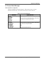
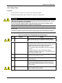
Table 9-1 System Status Messages ..........................................................................................................102
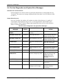
Table 9-2 Process Alarm Messages..........................................................................................................103
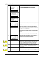
Table 9-3 On-Line Diagnostics and System Error Messages...................................................................104
Table 9-4 Procedure For Initiating Display and Keyboard Tests.............................................................105
Table 9-5 Procedure for Testing Relays and Analog Outputs .................................................................107
Table 10-1 Procedure for Calibrating Outputs.........................................................................................112
Table 10-2 Procedure for Restore Factory Calibration Values................................................................114
Table 10-3 Procedure for Specifying a Tagname or Other Display String..............................................115
Table 10-4 Procedure for Viewing Product Information and Changing the Stored Model Number ......116
Table 10-5 Procedure for Adjusting the Screen Contrast ........................................................................118
Table 10-6 Procedure for Entering a Password........................................................................................119
Table 10-7 Procedure for Resetting All Configuration to Factory Settings.............................................120
Table 10-8 Procedure for Switching Between Electrodes with DualCal .................................................121
Table 10-9 Solution Temperature Compensation Coefficients for Selected Treatment Types at
Specified Temperatures .....................................................................................................................123
3/00
9782 Series pH/ORP Analyzer/Controller - Operator’s Manual
ix
Table 10-10 Procedure for Determining a Solution Temperature Coefficient Experimentally...............123
Table 10-11 Procedure for Entering a Solution Temperature Coefficient...............................................124
Table 10-12 Procedure for Turning on Temperature Display..................................................................125
Table 10-13 Procedure for Specifying Relay Activation .........................................................................126
Table 10-14 Procedure for Replacing the Fuse........................................................................................128
Table 11-1 Part Numbers .........................................................................................................................130
Table F-1 Microprocessor Board Switch Settings ....................................................................................148
x
9782 Series pH/ORP Analyzer/Controller - Operator’s Manual
3/00
Figures
Figure 1-1 9782 Front Panel.........................................................................................................................3
Figure 1-2 Dual DAT or PFT Control Using Two Setpoints and Relays ....................................................9
Figure 1-3 DualCAT Control Using a Single Analog Output....................................................................10
Figure 3-1 Sample Nameplate ....................................................................................................................21
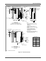
Figure 3-2-1 Mounting and Dimensions - Non-Backlit Display Option ...................................................23
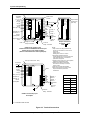
Figure 3-3-1 Mounting and Dimensions - Backlit Display Option ............................................................25
Figure 4-1 AC Power Terminals ................................................................................................................31
Figure 6-1 Dual Reagent CAT Typical Wiring Using Relay 1 to Select Reagent Feeder ........................66
Figure 6-2 Terminal Connections...............................................................................................................67
Figure 6-3 Terminal Connections...............................................................................................................68
Figure 6-4 Terminal Connections...............................................................................................................69
Figure 6-5 Terminal Connections...............................................................................................................70
Figure 6-6 Terminal Connections...............................................................................................................71
Figure 6-7 Backup Electrode Installation Using DualCal Alternate Electrode Calibration .....................74
Figure 6-8 Two Tank Batch Treatment with DualCal Alternate Electrode Calibration ...........................75
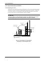
Figure 7-1 Automatic Electrode Wash Setup.............................................................................................78
Figure 7-2 Rinse and One-Point Calibration..............................................................................................81
Figure 7-3 Two-Point AutoCal Operation..................................................................................................82
Figure 10-1 Location of Power Fuse.........................................................................................................127
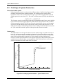
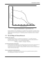
Figure A-1 Resistance vs. Temperature Characteristics of the Temperature Compensator ....................133
Figure B-1 Cyanide Treatment System ....................................................................................................135
Figure B-2 First Stage Cyanide Oxidation - Typical Titration Curve......................................................136
Figure C-1 Chrome Treatment System.....................................................................................................139
Figure C-2 Chrome Reduction - Typical Titration Curve........................................................................141
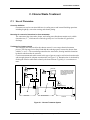
Figure D-1 Installation Diagram Simultaneous pH and ORP Measurements with 9782 pH/ORP
Analyzer and 7773-6o-o-40-o Electrode Mounting Plus ORP Electrode ....................................143
Figure F-1 Microprocessor Board DIP Switches ......................................................................................147
3/00
9782 Series pH/ORP Analyzer/Controller - Operator’s Manual
xi
xii
9782 Series pH/ORP Analyzer/Controller - Operator’s Manual
3/00
Introduction
1. Introduction
1.1 Description
Multi-function instrument
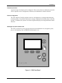
The Honeywell 9782 pH/ORP Analyzer/Controller (Figure 1-1) is a microprocessor-based
instrument for analysis of pH or ORP (Oxidation Reduction Potential, also referred to as Redox)
in industrial processes. The pH, ORP and temperature can be measured simultaneously,
depending on configuration (see Section 5). The units of measure are pH, mV, and °C.
Resolution is 0.01 pH, 1 mV ORP, and 1 °C.
User interface
An easy-to-read display provides instant access to process values. The displays of process values
show the instrument’s tagname (or other configurable text) at the top of the screen.
Every display includes an “alarm stripe”, a line dedicated to displaying process alarm messages,
status messages, and system diagnostic messages, whenever any are active.
Dedicated-function membrane keys to the right of the display on the front panel are used to:
•
cycle through the displays of real-time values
•
access configuration, calibration, and maintenance menus
•
change and enter setpoints and other parameters
In addition, three variable function keys are below the display. The function of each of these
“soft keys” depends on the purpose of the screen currently on display. Soft key labels are always
displayed at the bottom of the screen, immediately above the relevant function key.
Easy to configure
Menu-driven configuration is fast and easy. Only configuration parameters related to features
supported by the hardware and relevant to the specific application are displayed.
Input
Input to the 9782 can be from any Honeywell pH electrode/preamplifier system or Durafet II
electrode with Cap Adapter at distances up to 914.4 m (3000 ft). If the Analyzer/Controller is
equipped with an optional internal preamplifier, input can come directly from any glass pH or
ORP electrode located within 3.66 m (12 ft) of the analyzer or directly from a Durafet II pH
electrode within 15.24 m (50 ft).
3/00
9782 Series pH/ORP Analyzer/Controller - Operator’s Manual
1
Introduction
Outputs
Optional isolated 0-1 V, 0-10 V and 4-20 mA outputs are available. Use these analog outputs for
retransmission of process variables, or for Current Adjusting Type control using an output signal
that is directly proportional to the input (see 1.5.3).
Relays
Two 2A SPDT alarm/control relays are standard, with an additional two 3A relays (either general
purpose or hermetically sealed) available as an option. These relays can be used to:
•
take advantage of special features such as automatic cleaning of electrodes
•
control process variables (see 1.5.3)
•
annunciate alarms
1.2 Features
Storage of calibration data for two electrodes
The DualCal feature allows storage of calibration data for two electrode assemblies. The second
electrode can be used as a manual backup or in a two-tank batch control setup.
Standard and solution temperature compensation
In addition to standard temperature compensation (for electrode response to temperature), the
9782 Analyzer/Controller also features solution temperature compensation (to adjust for the
solution’s change in pH as temperature changes). These temperature-induced changes are
significant in analysis of high purity water.
Automatic electrode washing and calibration
The standard AutoClean and AutoCal features periodically rinse and calibrate electrodes
automatically. The schedule and duration of the operations are configurable. AutoCal can be
configured for one or two point calibrations. Internal relays actuate external solenoid valves to
control the flow of the buffer solutions and rinse water to the electrodes.
Automatic buffer recognition
The instrument automatically recognizes six commonly used buffer solutions and the temperature
variation characteristic of each. This simplifies manual calibration, and permits automatic
calibration.
2
9782 Series pH/ORP Analyzer/Controller - Operator’s Manual
3/00
Introduction
Password protection
A password (up to four digits) can be configured. If the security feature is enabled, the password
will be required to access configuration, calibration, and maintenance software functions.
Extensive diagnostics
The 9782 Analyzer/Controller performs extensive self-diagnostics as a background task during
normal operation. If a problem is detected, a message is displayed on the alarm stripe to alert the
operator. In addition, the operator can initiate keypad and display tests using Maintenance Menu
functions.
Watertight corrosion-resistant case
The 9782 is enclosed in a watertight and corrosion resistant industrial case, designed for panel,
pipe or wall mounting. It has an EMI/RFI shielded plastic case.
F1
F2
F3
+RQH\ZHOO
Figure 1-1 9782 Front Panel
3/00
9782 Series pH/ORP Analyzer/Controller - Operator’s Manual
3
Introduction
1.3 Operating the Analyzer/Controller
Front panel keys used for all operator tasks
As shown in Figure 1-1, five keys with dedicated functions are on the front panel. In addition,
three “soft keys” vary their function according to the needs of the screen on display. Use of the
keys is described in Table 1-1.
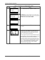
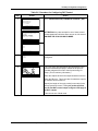
Table 1-1 Key Functions
Key
Name
Use
DISPLAY
When process values are on display: Use DISPLAY to cycle
through available real-time displays.
When the main menu (Configuration, Calibration,
Maintenance, I/O Setup) is on display: Use DISPLAY to
return to displaying process values.
MENU
When process values are on display: Use MENU to access
the menus. If the security feature is enabled, the display will
prompt for entry of the password before access to the menus
is permitted. (Enter the password using the procedure for
editing a parameter numeric value as described on the next
page.)
When any menu or configuration screen is on display: Use
MENU to go up a level in the display hierarchy. Frequently this
means returning to the main menu.
UP
When a menu or configuration screen is on display: Use
UP to highlight a different item.
When changing a numerical value: Use UP key to increment
the value of the digit at the cursor.
DOWN
When a menu or configuration screen is on display: Use
DOWN to highlight a different item.
When changing a numerical value: Use DOWN to
decrement the value of the digit at the cursor.
ENTER
When a menu item is highlighted: Use ENTER to select it.
When editing a parameter: Use ENTER to save the new
value.
F1
4
F1, F2, F3
[function
keys]
When a “soft key” label is displayed below the alarm
stripe: Use the function key directly below the label to perform
the action.
9782 Series pH/ORP Analyzer/Controller - Operator’s Manual
3/00
Introduction
Selecting a parameter for edit
To select a parameter for edit:
•
display the screen containing the parameter
•
use the UP or DOWN keys to highlight the parameter name
•
press the ENTER key to highlight the displayed current value
Editing a parameter assignment from a list of available choices
To edit a parameter having a text string as an assigned value:
•
select the parameter and highlight its current value as described above
•
use the UP or DOWN keys to display the other valid choices
•
when your choice is displayed, press ENTER
Editing a parameter numeric value
To edit a parameter having a numeric value:
•
select the parameter and highlight its current value as described above; the ← and →
soft keys will be displayed (During calibration the ← and → soft keys will be
displayed once the UP or DOWN key has been pressed.)
•
use the ← or → soft keys to move the cursor to the digit to be changed
•
use the UP and DOWN keys to increment or decrement the value
•
when all digits necessary have been changed, press ENTER
Entering and retrieving data
During I/O setup, configuration and calibration, while the unit is either retrieving data from
memory or entering a new data value into memory, a time period will elapse until this action is
complete. For the duration of this time period (which can be as great as 2 minutes for a large step
change in values) a message will appear on the alarm stripe. If data is being retrieved from
memory, the message will be “Retrieving Data” and if a new value is being stored in memory,
the displayed message will be “Entering Data”.
Placing the unit in Hold mode
To put the Analyzer/Controller in Hold mode, maintaining a constant output and alarm condition,
(and disabling solution temperature compensation if used) use the HOLD soft key available on
the appropriate screens. “HOLD ACTIVE” will be displayed on the alarm stripe.
Use of Hold mode is recommended:
•
Before starting manual calibration.
•
Alarms are always held during an Automatic clean/calibration. The user selects
whether outputs are held during these automatic functions. In either case the alarm
stripe will display “HOLD ACTIVE.”
•
Before making configuration changes that should not take effect immediately.
To take the unit out of Hold mode, press HOLD again.
3/00
9782 Series pH/ORP Analyzer/Controller - Operator’s Manual
5
Introduction
Controlling an AutoClean and/or AutoCal operation manually
To initiate an Auto/Clean and/or AutoCal operation manually, press the DISPLAY key until the
AutoClean/Cal screen is displayed. Next press the “START” soft key.
This display can also be used to see how much time is remaining during an automatic operation.
When AutoClean and/or AutoCal are active, the alarm stripe will display “AUTOSEQUENCE”,
and the AutoClean/Cal display will show the remaining time.
If necessary, pause the operation using the “PAUSE” soft key. To resume the operation, press
“PAUSE” again. To cancel the operation, use the “STOP” soft key.
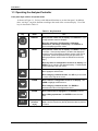
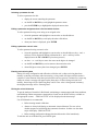
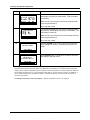
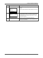
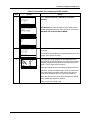
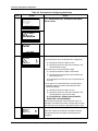
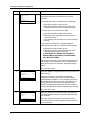
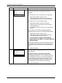
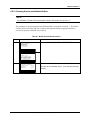
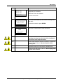
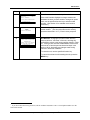
1.4 Menu Hierarchy
Menus for every task
For your convenience, menus are provided for configuration, calibration, maintenance, and I/O
setup tasks. The menu hierarchy is shown in Table 1-2. Not every menu item applies to every
system.
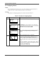
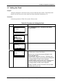
Table 1-2 9782 pH Analyzer/Controller Menu Hierarchy
Menu Item
Described in
Section
set up Analyzer/Controller to implement
your alarm and control strategy
5
CAT/RETRANSMISSION
configure parameters for using analog
outputs for control and retransmission of
process values
5.4
ALARMS
specify alarm setpoints, deadbands, and
delays
5.6
DISCRETE CONTROL
specify setpoints, range limits, etc. to use
relays for control
5.5
ADVANCED FEATURES
set up automatic cleaning and calibration
of electrodes and sets up clock
5.7 and 5.8
CONFIGURATION
select buffers for automatic buffer
recognition and perform manual calibration
8
pH BUFFER CAL
calibrate pH system manually using one or
two reference solutions
8.2
ORP CAL
calibrate ORP system manually using a
reference solution or voltage input
SAMPLE CAL
calibrate pH system manually using a
standard meter
AUTO BUFFER CAL
calibrate pH electrodes manually using
automatic buffer recognition
8.6.3
AUTO BUFFER SETUP
select buffers for automatic buffer
recognition
8.6.2
CAL DIAGNOSTICS
display standardization and slope values
CALIBRATION
6
Purpose
9782 Series pH/ORP Analyzer/Controller - Operator’s Manual
8.4 or 8.5
8.3
8.7
3/00
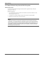
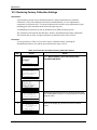
Introduction
Menu Item
MAINTENANCE
OFF-LINE FUNCTIONS
do occasional system tasks
9 and 10
[see functions listed below]
[see below]
test display
9.5.1
KEYBOARD TEST
test keyboard
9.5.1
OUTPUT TESTS
test relays and analog outputs
9.5.2
OUTPUT CALIBRATION
calibrate outputs electrically
10.2
CALIBRATION RESET
set standardization offset and slope values
back to zero
10.3
[see functions listed below]
[see below]
INSTRUMENT TAGGING
configure tagname or other text to be
displayed when no alarms are active
10.4
PRODUCT INFO
view software version and stored model
number; if a special technical support
password is known, alter model number in
memory (in case of hardware upgrades)
10.5
SCREEN CONTRAST
adjust display contrast
10.6
SECURITY
assign password to limit access to
configuration, calibration, and maintenance
functions
10.7
RESET UNIT
reset all configuration and calibration
values back to factory settings
10.8
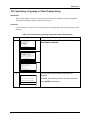
ELECTRODE FUNCTIONS
[see functions listed below]
[see below]
SELECT ELECTRODE
specify which electrode is being used if
calibration values for two electrodes are
stored (DualCal)
10.9
SOLUTION TEMP COMP
enter a temperature coefficient if solution
temperature compensation feature is used
10.10
DURAFET TEMP DISPLAY
turn Durafet temperature display on and off
10.11
specify whether relays should be activated
or de-activated on alarm (or when discrete
control output is on)
10.12
RELAY ACTIVATION
3/00
Described in
Section
DISPLAY TEST
INSTRUMENT SETUP
I/O SETUP
Purpose
choose features, make relay and analog
output assignments
9782 Series pH/ORP Analyzer/Controller - Operator’s Manual
5.3
7
Introduction
1.5 Planning
1.5.1 Overview
Configuration system minimizes decisions
The 9782 was designed for easy configuration using menu displays and the keys on the front
panel. Numeric values such as setpoints and range limits are easy to enter using the UP and
DOWN keys and function keys (see 1.3). Other configuration parameter assignments are
selected by scrolling through a list of available choices using the UP and DOWN keys.
During configuration only those parameters and choices relevant to features supported by your
Analyzer/Controller’s hardware will be available for configuration. For example, if the model
purchased does not contain hardware for the optional analog outputs, then none of the screens
relating to output configuration will be applicable.
Although configuration is a simple process, to make best use of the 9782 Analyzer/Controller
and its features, a little advance planning is recommended.
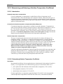
1.5.2 Using Relays
Relays assigned automatically by priority
Every 9782 model includes two internal relays. Two more relays are available as an option.
Many features use relays. During system setup, the first stage of configuration, you choose the
features to be used. Based on your selections, the software will automatically assign relays based
on the priority scheme described below. You will not be permitted to select features requiring
more that the available number of relays.
Relay priority scheme
During I/O setup (see 5.3) the 9782’s software will assign relays for the features listed below in
the order shown. The 9782 implements this scheme for you automatically. However, it is
presented here to make you aware of which features use relays, and of the trade-offs involved
when selecting features.
1) Using an alternate electrode (DualCal) has top priority. Relay 4 will automatically be
assigned to switch between electrodes. If the unit has only two relays, DualCal can still be
used, but switchover of electrode input must be done manually (see 6.4.2).
2) Automatic functions AutoClean and AutoCal have second priority. (Manual calibration
described in Section 8 does not require use of any relays.)
8
•
AutoClean always uses Relay 1 to activate the solenoid valve used to direct washing
fluid to the electrode (see Section 7 for piping).
•
AutoCal with one reference solution (standardization for zero adjustment) uses Relay 2
to activate the solenoid value used to direct the reference solution to the electrode (see
Section 7 for piping).
9782 Series pH/ORP Analyzer/Controller - Operator’s Manual
3/00
Introduction
•
Using a second reference solution for AutoCal (permitting slope adjustment to match
instrument gain to the electrode output response) requires Relay 3 to activate the
solenoid valve for the second reference solution.
3) Use of relays for one of the discrete control strategies (see 1.5.3) has third priority.
•
Up to four relays can be used for On/Off cycle timers.
•
One or two relays can be used for Duration Adjusting Type (DAT) control.
•
One or two relays can be used for Pulse Frequency Type (PFT) control.
4) Use of a relay for DualCat switchover has next priority, permitting two reagents to be fed
using a single analog output for Current Adjusting Type control.
5) Lowest priority is given to use of relays for activation of an annunciator for process alarms
and/or system errors. (Note that any problems found by the Analyzer/Controller’s selfdiagnostics will always be displayed on the alarm stripe.)
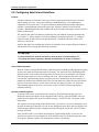
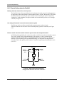
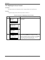
1.5.3 Deciding on a Control Strategy
All 9782 models can use relays for control
All 9782 models have at least two relays. (Two more relays are optional.) These relays can be
used to control process variables using one of the three types of discrete control available:
•
On/Off Control using one to four cycle timers with configurable setpoint, deadband,
cycle period, and “on” time.
•
PFT (Pulse Frequency Type) Proportional-Only Control using one or two relays. The
pulse output is generated by repeated relay contact opening and closure. The frequency
of the pulse is proportional to the deviation from the configurable setpoint. The
proportional band limit and maximum pulse frequency rate are also configurable. This
type of output is used to control such devices as pulse-type electronic metering pumps.
•
DAT (Duration Adjusting Type) Proportional-Only Control using one or two relays.
Also known as time-proportioning control, DAT cycles a relay output on and off,
varying the “on” time in proportion to the deviation from setpoint. This type of output
is used to control devices such as solenoid valves.
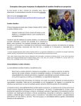
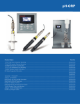
PFT and DAT can use two relays to control two reagents. Figure 1-2 diagrams this application.
OUTPUT
100 %
base
addition acid
addition
0%
PB1
0
SP 1 SP2
7
pH
PB2
14
Figure 1-2 Dual DAT or PFT Control Using Two Setpoints and Relays
3/00
9782 Series pH/ORP Analyzer/Controller - Operator’s Manual
9
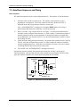
Introduction
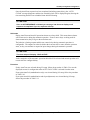
Optional analog outputs for control
Current and voltage outputs are available as options. These analog outputs can be used to
retransmit a process variable using an output signal that is directly proportional to the input.
This directly proportional analog output can also be used for Current Adjusting Type (CAT)
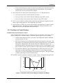
control. (Despite the name of this control type, voltage outputs can also be used.)
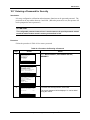
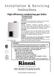
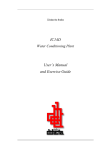
DualCAT is a feature that permits control of two reagents with a single analog output. (An
internal relay is used to make the switchover.) This scheme is diagrammed in Figure 1-3.
When an output is used to retransmit a process variable, the values representing 0 % and 100 %
outputs are configurable.
In CAT control the process values for the setpoint and proportional band limit are configurable.
In addition, if the DualCAT feature is used, a “failover” value can be configured. If the feature is
enabled, then this value will be used as the output if the Analyzer/Controller’s diagnostics detect
a problem with the system.
To control two reagents with two output signals, simply configure the output ranges
appropriately. No switching relay is needed if two outputs are used.
OUTPUT
100%
base
addition
acid
addition
CAT1PB CAT1SP
CAT2SP
0%
0
2
4
6
8
10
CAT2PB
12
14
SWITCHOVRRLY
pH
Figure 1-3 DualCAT Control Using a Single Analog Output
Selecting a strategy
When considering whether to use On/Off control or one of the proportional-only strategies,
compare the requirements of your application with the benefits of each control type.
Proportional control will usually provide faster batch treatment with less overshoot than On/Off
control. However, it is important to note that proportional-only control is recommended only for
batch processes and for pretreatment in continuous neutralization systems.
Proportional-only control does not include any reset action. As a result, changes in reagent
demand that occur in continuous processes are not accommodated and control will not reach the
setpoint. In a batch process, reagent is added until a setpoint is reached and the batch is not
emptied until this occurs.
If you decide to use proportional-only control, select the type based on the input requirements of
the device to be controlled. See Appendix E for a discussion of tuning proportional-only control.
10
9782 Series pH/ORP Analyzer/Controller - Operator’s Manual
3/00
Introduction
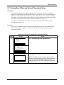
1.6 Overview of Installation and Setup Tasks
Setup tasks described in this manual
This manual contains instructions for all installation and operation tasks relating to the
Analyzer/Controller. (Instructions for installing and using the electrodes are provided in the
manuals supplied with the electrodes.) Table 1-3 provides an overview of the
Analyzer/Controller installation tasks, as well as providing references to the relevant sections of
the manual.
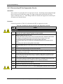
Table 1-3 Overview of Analyzer/Controller Installation Tasks
Sequence
3/00
Task
Section
1
Consider the environmental and electrical specs when
selecting a site to install the Analyzer/Controller.
2
2
Unpack, inspect and mount the unit.
3
3
Install any optional hardware.
3
4
Check tag to confirm that unit is compatible with the voltage at
your site.
4
5
Install power wiring.
4
6
Perform I/O setup and configure the software to implement
your control strategy.
5
7
Wire inputs and outputs to match I/O setup in Step 6.
6
8
If AutoClean and AutoCal will be used, install necessary
piping and valves.
7
9
If AutoCal will not be used, calibrate the system manually.
8
10
Specify whether relays should be energized or de-energized
on alarm.
10
11
If solution temperature compensation will be used, enter a
solution temperature coefficient. (If desired, specify that
temperature will be one of the displayed real-time values.)
10
12
Configure a tagname or other text string to be displayed at the
top of the screens showing real-time process values.
10
13
To limit access to I/O setup, configuration, calibration, and
maintenance functions, enter a password.
10
14
Display model number stored in memory and software version
number. Note these for future reference. (If you call for
technical assistance, you will need this information.)
10
9782 Series pH/ORP Analyzer/Controller - Operator’s Manual
11
Introduction
The manual also contains:
12
•
information about diagnostics, status messages, and system error messages
(Section 9)
•
instructions for returning all parameter values to the factory settings (Section 10)
•
instructions for calibrating the outputs and changing the fuse (Section 10)
•
parts list (Section 11)
•
supplementary information for special applications and proportional control tuning tips
(appendices).
9782 Series pH/ORP Analyzer/Controller - Operator’s Manual
3/00
Specifications and Model Number
2. Specifications and Model Number
2.1 Specifications
Display
LCD dot matrix display, 128 by 64 dpi. Backlit display – solid state LED. Displays pH/ORP,
temperature, time, alarm conditions, alarm setpoints, calibration, output limits and diagnostics.
Display Ranges
pH: –2.00 pH to +14.00 pH; resolution 0.01 pH.
ORP: –1638 to +1638 mV; resolution 1 mV.
Temperature: –10 to +140 °C; resolution 1 °C.
Display Scan Mode
Key used to cycle through displays of measured parameters and autosequence operation status.
Alarm messages, status messages, and diagnostic messages available on all displays.
Keypad
Monoplanar front panel with 8 keys. Push-button entry with tactile feedback.
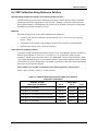
Auto Buffer Recognition
Recognizes 4.01, 6.86, 7.00, 9.00, 9.18, 10.00 pH standard buffer solutions with temperature
correction from 0 °C to 60 °C (32 °F to 140 °F).
AutoCal Automatic Calibration and AutoClean Electrode Washing Schedule Settings
Clock Cycle: 28 days with day, hour, minute resolution.
Rinse Time: 60-1999 seconds.
Buffer Duration: 60-1999 seconds.
Resume Process Time Delay: 1-1999 seconds.
Calibration Interval: Adjustable, number of rinse cycles between one-point calibrations; or
number of one-point calibrations between two-point calibrations.
Performance under reference operating conditions
Accuracy: ± 0.02 pH, or ± 2 mV (display).
Drift: Negligible.
Repeatability: ± 0.1 % of span ± 1 count.
Reference Operating Conditions: 25 ± 1 °C; 10-40 % RH; 120 Vac
Operating Influences under normal operating conditions
Effect on accuracy (% of span): Temperature: 0.05 % per °C; RH: < 1 %; Line Voltage:
< 0.1 % per volt.
Power Loss: Memory retention by EEPROM (no batteries).
3/00
9782 Series pH/ORP Analyzer/Controller - Operator’s Manual
13
Specifications and Model Number
Operating Conditions
Ambient Temperature: Normal 0 °C to 60 °C (32 °F to 140 °F), extreme –10 °C to +60 °C (–4 °F
to 140 °F); storage –30 °C to +70 °C (–22 °F to 158 °F).
Line Voltage: Normal 120 ± 10 % Vac, (extreme 100 Vac to 132 Vac, 47 Hz to 63 Hz.)
Normal 240 ± 10 % Vac, to 264 Vac, (extreme 200 Vac to 264 Vac, 50 Hz to
60 Hz.)
RH: 90 % maximum non-condensing @ 40 °C (104 °F) max.
Installation Category: II
Pollution Degree: 2
Altitude: < 20000 M (6562 ft)
Output
Adjustable to within 0.01 mA, repeatable to within ± 0.1 % of span.
Optional Output
Two or three 4-20 mA outputs are available via an optional plug-in circuit card and program
module. Isolated from ground, inputs and each other.
Maximum isolation voltage: 240 Vac (will withstand 1500 V hi-pot test).
Output adjustable: to within 0.01 mA.
Repeatability: ± 0.1 % of span. 600 ohm maximum load resistance.
Output Range
Adjustable to any pH/ORP/TEMP range within the display range.
Output Signals
Proportional to selected output range.
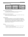
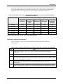
9782P -_ _ - 00:
9782P -_ _ - VC:
9782P -_ _ - C2:
9782P -_ _ - C3:
None
0-1 V or 0-10 Vdc, or isolated 4-20 mA dc
(600 ohms maximum load)
Two isolated 4-20 mA dc.
Three isolated 4-20 mA dc.
Standard Alarm/Control Relays
Two SPDT Form C general purpose relays rated 0.6 amps at 120/240 Vac, 0.6 amps at 110 Vdc,
2 amps at 30 Vdc. Maximum switching power for ac, 125 VA resistive; for dc, 60 W resistive.
Optional Alarm/Control Relays
9782P -_ _ - R0:
14
Two hermetically sealed Form C, rated at 3 amps at
120 Vac, 28 Vdc, 0-1 V or 0-10 V or isolated 4-20 mA
9782 Series pH/ORP Analyzer/Controller - Operator’s Manual
3/00
Specifications and Model Number
Control Settings
On/off period: 1 to 1000 seconds
On/off percent “on” time: 0 to 100 %, 1 % resolution.
Setpoint and proportional band limit ranges: ± 19.99 pH, ± 1999 mV, –10 °C to +100 °C (14 °F
to 284 °F), one count resolution.
DAT cycle period: 1 second to 200 seconds.
PFT maximum frequency: 1 to 200 pulses/minute.
PFT pulse width: 50 ms, compatible with electronic pulse-type metering pumps.
Temperature Compensation
Conventional compensation for changing electrode output (Nernst response), plus selectable
solution temperature compensation for high-purity water.
Power Requirements
108-132/216-264 Vac, 47-63 Hz, 15 VA. Memory retained by EEPROM when power is off.
Fuse Rating
120 V operation: 0.25 amp/250 V
240 V operation: 0.125 amp/250 V
Case
Gray Noryl plastic, waterproof and corrosion resistant. Interior conductive coating to provide
effective RFI/EMI shielding.
Case Dimensions
156 x 156 x 178 mm (6 1/8 x 6 1/8 x 7 in.); panel cutout 141 x 141 mm (5.53 x 5.53 in.).
Weight
1.8 kg (4 lb).
Mounting
Panel mounting hardware supplied. Surface and pipe mounting hardware available. See Figure
3-2 or the Parts List.
3/00
9782 Series pH/ORP Analyzer/Controller - Operator’s Manual
15
Specifications and Model Number
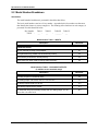
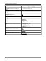
2.2 Model Number Breakdown
Introduction
The model number breakdown is presented in the tables that follow.
The basic model number consists of a key number. Appended to this key number are characters
that identify the features in various categories. The meaning of the characters in each category is
presented in a table identified below.
Key Number
9782P -
Table I
__ -
Table II
Table III Table IV
__
- _____ - __
Model Number Table I - INPUTS
Description
Model No.
pH/ORP Electrodes
pH from external pre-amp or Cap Adapter
01
direct glass/antimony pH/ORP electrode/internal preamp
02
direct Durafet pH electrode, internal preamp
03
Direct Glass from HPW 7000 Hi-pHurity Water Assembly
04
Model Number Table II - AVAILABLE OUTPUTS
(in addition to two standard relays)
Description
16
Model No.
no analog outputs nor additional relays
00
one analog output: 4 to 20 mA, or 0 to 1 V or 0 to 10 V
VC
two analog outputs: both 4 to 20 mA
C2
three analog outputs: all 4 to 20 mA
C3
two additional relays (hermetically sealed) and one analog output: 4 to 20
mA, or 0 to 1 V or 0 to 10 V
R0
9782 Series pH/ORP Analyzer/Controller - Operator’s Manual
3/00
Specifications and Model Number
Model Number Table III - OPTIONS
Description
Model No.
User’s Manual
English
E____
Pipe Mounting Kit
none
_0___
one kit
_1___
Tagging
none
__0__
linen
__L__
stainless steel
__S__
Power
factory set for 110/120 Vac
___0_
factory set for 220/240 Vac
___1_
____0
Future
Model Number Table IV – BACKLIT DISPLAY OPTION
Description
Backlit display option
3/00
Model No.
No
00
Yes
BD
9782 Series pH/ORP Analyzer/Controller - Operator’s Manual
17
Specifications and Model Number
18
9782 Series pH/ORP Analyzer/Controller - Operator’s Manual
3/00
Unpacking, Preparation, and Mounting
3. Unpacking, Preparation, and Mounting
3.1 Overview
Introduction
This section contains instructions for unpacking, preparing, and mounting the
Analyzer/Controller. Instructions for wiring are provided in Sections 4 and 6. Software
configuration is described in Section 5.
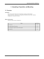
What’s in this section?
The topics in this section are listed below.
Topic
3/00
See Page
3.1 Overview
19
3.2 Unpacking and Preparing
20
3.3 Installing the Optional Internal Preamplifier
21
3.4 Mounting
22
9782 Series pH/ORP Analyzer/Controller - Operator’s Manual
19
Unpacking, Preparation, and Mounting
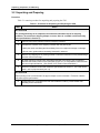
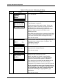
3.2 Unpacking and Preparing
Procedure
Table 3-1 contains procedure for unpacking and preparing the 9782.
Table 3-1 Procedure for Unpacking and Preparing the 9782
Step
Action
ATTENTION
For prolonged storage or for shipment, the instrument should be kept in its shipping
container. Do not remove shipping clamps or covers. Store in a suitable environment only
(see specifications in Section 2).
1
Carefully remove the instrument from the shipping container.
2
Compare the contents of the shipping container with the packing list.
• Notify the carrier and Honeywell immediately if there is equipment damage or shortage.
• Do not return goods without contacting Honeywell in advance.
3
Remove any shipping ties or packing material. Follow the instructions on any attached tags,
and then remove such tags.
4
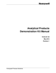
All 9782 Analyzer/Controllers are calibrated and tested at the factory prior to shipment.
Examine the model number on the nameplate (Figure 3-1) to verify that the instrument has
the correct optional features. (See Section 2 for model number breakdown.)
5
Select an installation location that meets the specifications in Section 2. The 9782 can be
panel-, wall- or pipe-mounted (see 3.4).
ATTENTION
Pipe mounting is not recommended if the pipe is subject to severe vibration. Excessive vibration
may affect system performance.
6
20
If extremely hot or cold objects are near the installation location, provide radiant heat
shielding for the instrument.
9782 Series pH/ORP Analyzer/Controller - Operator’s Manual
3/00
Unpacking, Preparation, and Mounting
Honeywell
York, PA U.S.A.
ATTENTION - UNIT SET FOR 240 VAC
9782P-01-VC-E0010-00
S/N: 9751Y712345670001
USA WARRANTY ASSISTANCE - 1 - 800-423-9883
120/240 VAC 50/60 Hz 15VA
Contact Rating 1 & 2: 0.6 Amps at 120/240 VAC,
0.6 Amps at 110 VDC, and 2 Amps at 30 VDC.
If installed 3 & 4: 3 Amps at 120 VAC, 28 VDC. CE
Directions: 70-82-25-73
.
Figure 3-1 Sample Nameplate
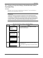
3.3 Installing Optional Internal Preamplifier
Instructions elsewhere
If an optional internal preamp is to be installed in the 9782, follow the directions provided with
the preamp kit.
3/00
9782 Series pH/ORP Analyzer/Controller - Operator’s Manual
21
Unpacking, Preparation, and Mounting
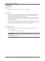
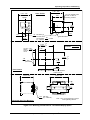
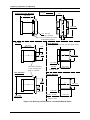
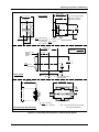
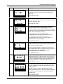
3.4 Mounting
Introduction
The 9782 Analyzer/Controller can be panel-, wall- or pipe-mounted.
Panel-mounting
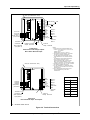
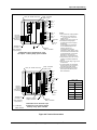
Figures 3-2-1 and 3-3-1 show panel cutout dimensions. They also illustrate how the instrument
is attached to a panel by clamping the edges of the cutout between the case flange and the
supplied U-bracket which is fastened to the rear of the case.
The panel may be up to 3/8 in. thick. Cutouts for adjacent 9782 Analyzer/Controllers may be no
closer than 0.687 in. horizontally and 0.937 in. vertically, resulting in a nominal edge-to-edge
bezel separation of 0.078 in.
Note that if the panel already has a cutout for a 7082 instrument, the same cutout can be used for
the 9782. If the panel has a cutout for a 7070, 7075, 7076, 7077, or 7078 instrument, a Reducer
Panel Kit is available for mounting the 9782. The part number is in Section 11.
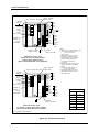
Wall- and pipe-mounting
A bracket is available as an option for wall or pipe mounting the unit as shown in Figures 3-2-1,
3-2-2, 3-3-1, and 3-3-2.
The mounting kit part numbers are in Section 11.
ATTENTION
Pipe mounting is not recommended if the pipe is subject to severe vibration. Excessive vibration
may affect system performance.
22
9782 Series pH/ORP Analyzer/Controller - Operator’s Manual
3/00
Unpacking, Preparation, and Mounting
7.00 ± .040
177.80 ± 1.02
Case Outline
6.12 ± .030
155.57 ± 0.76
Square
6.00
152.40
(2) ¼-20 Tapped Holes
in rear of case for
mounting bracket
C
L
4.81
122.17
CL
1.37
34.92
2.75
69.85
.87 Dia holes (4)
22.22 for lead wires,
.50
accomodates
conduit
12.70
by customer
5.516
140.11
min space .687
between
17.45
horizontal
cutouts
Terminal Boards
+.047
-0
+1.19
-0
2.41
61.21
LEGEND:
inches
millimeters
2.76
70.05
5.516
140.11
.125
3.18 R max
permissible
+.047
-0
+1.19
-0
2.76
70.05
.937
23.81
Panel Cutout
min space between
vertical cutouts
7.43 ± .070
188.72 ± 1.78
7.68 ± .060
195.07 ± 1.52
3.06
77.80
1.00 IPS Pipe
25.40 (by customer)
Horizontal Rear Pipe Mounting
Note 1: Do not exceed 80 lb-in torque
when tightening fastners.
Figure 3-2-1 Mounting and Dimensions - Non-Backlit Display Option
3/00
9782 Series pH/ORP Analyzer/Controller - Operator’s Manual
23
Unpacking, Preparation, and Mounting
Vertical Rear Pipe Mounting
inches
LEGEND: millimeters
7.43 ±.070
188.72 ±1.78
3.06
77.80
7.68 ±.060
195.07 ±1.52
1.00 IPS Pipe
25.40 (by customer)
Note 1: Do not exceed 80 lb-in torque
when tightening fastners.
Top View
Panel Mounting
into existing 7075, 7076, 7077, and 7078 series cutouts
7.43 ±.070
188.72 ±1.78
1.50
38.10
C
L
3.00
76.20
C
L
6.43 ±0.70
163.32 ±1.78
1.06 ±.025
26.92 ±0.64
Four holes in bracket or
1/4 dia. mounting bolts
(bolts by customer)
R.H. Side View
Wall Mounting
.25 max.
6.35
Customer Panel
6.27 ±.040
159.26 ±1.02
Panel Mounting
6.63
168.40
C
L
C
L
6.43 ±0.70
163.32 ±1.78
3.31
84.07
1.00 ±.025
25.40 ±0.64
7.68 ±.060
195.07 ±1.52
.12 min. .37 max.
3.04
9.40
Customer Panel
6.27 ±.040
159.26 ±1.02
Figure 3-2-2 Mounting and Dimensions - Non-Backlit Display Option
24
9782 Series pH/ORP Analyzer/Controller - Operator’s Manual
3/00
Unpacking, Preparation, and Mounting
7.21 ± .040
183.13 ± 1.02
Case Outline
6.12 ± .030
155.57 ± 0.76
Square
6.00
152.40
(2) ¼-20 Tapped Holes
in rear of case for
mounting bracket
C
L
4.81
122.17
CL
.87 Dia holes (4)
22.22 for lead wires,
.50
accomodates
conduit
by customer 12.70
1.37
34.92
2.75
69.85
5.516
140.11
min space .687
between
17.45
horizontal
cutouts
Terminal Boards
+.047
-0
+1.19
-0
2.41
61.21
inches
LEGEND: millimeters
2.76
70.05
5.516
140.11
.125
3.18 R max
permissible
+.047
-0
+1.19
-0
2.76
70.05
.937
23.81
Panel Cutout
min space between
vertical cutouts
7.64 ± .070
194.06 ± 1.78
7.68 ± .060
195.07 ± 1.52
3.06
77.80
1.00 IPS Pipe
25.40 (by customer)
Horizontal Rear Pipe Mounting
Note 1: Do not exceed 80 lb-in torque
when tightening fastners.
Figure 3-3-1 Mounting and Dimensions - Backlit Display Option
3/00
9782 Series pH/ORP Analyzer/Controller - Operator’s Manual
25
Unpacking, Preparation, and Mounting
Vertical Rear Pipe Mounting
inches
LEGEND: millimeters
7.64 ±.070
194.06 ±1.78
3.06
77.80
7.68 ±.060
195.07 ±1.52
1.00 IPS Pipe
25.40 (by customer)
Note 1: Do not exceed 80 lb-in torque
when tightening fastners.
Top View
Panel Mounting
into existing 7075, 7076, 7077, and 7078 series cutouts
7.64 ±.070
194.06 ±1.78
1.50
38.10
C
L
3.00
76.20
C
L
6.43 ±0.70
163.32 ±1.78
1.27 ±.025
32.26 ±0.64
Four holes in bracket or
1/4 dia. mounting bolts
(bolts by customer)
R.H. Side View
Wall Mounting
.25 max.
6.35
Customer Panel
6.27 ±.040
159.26 ±1.02
Panel Mounting
6.63
168.40
C
L
C
L
6.43 ±0.70
163.32 ±1.78
3.31
84.07
1.21 ±.025
30.73 ±0.64
7.68 ±.060
195.07 ±1.52
.12 min. .37 max.
3.04
9.40
Customer Panel
6.27 ±.040
159.26 ±1.02
Figure 3-3-2 Mounting and Dimensions - Backlit Display Option
26
9782 Series pH/ORP Analyzer/Controller - Operator’s Manual
3/00
Power Wiring
4. Power Wiring
4.1 Overview
Introduction
This section contains instructions for installing ac power wiring for the Analyzer/Controller, in
preparation for configuring the software and performing I/O setup as described in Section 5.
We recommend that you wait to install input and output wiring (see Section 6) until after I/O
setup. During I/O setup the software will determine for you which relay to use for each feature.
What’s in this section?
The topics in this section are listed below.
Topic
3/00
See Page
4.1 Overview
27
4.2 General Wiring Practices
28
4.3 Power Wiring Considerations
29
4.4 Installing Power Wiring
30
9782 Series pH/ORP Analyzer/Controller - Operator’s Manual
27
Power Wiring
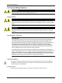
4.2 General Wiring Practices
WARNING
Wiring should be performed by qualified personnel only.
Safety precaution
WARNING
A disconnect switch must be installed to break all current carrying conductors. Turn off power
before working on conductors. Failure to observe this precaution may result in serious personal
injury.
WARNING
An external disconnect switch is required for any hazardous voltage connections to the relay
outputs.
Avoid damage to components
ATTENTION
This equipment contains devices that can be damaged by electrostatic discharge (ESD). As
solid state technology advances and as solid state devices get smaller and smaller, they become
more and more sensitive to ESD. The damage incurred may not cause the device to fail
completely, but may cause early failure. Therefore, it is imperative that assemblies containing
static sensitive devices be carried in conductive plastic bags. When adjusting or performing any
work on such assemblies, grounded work stations and wrist straps must be used. If soldering
irons are used, they must also be grounded.
A grounded work station is any conductive or metallic surface connected to an earth ground,
such as a water pipe, with a 1/2 to 1 megohm resistor in series with the ground connection. The
purpose of the resistor is to current limit an electrostatic discharge and to prevent any shock
hazard to the operator. The steps indicated above must be followed to prevent damage and/or
degradation, which may be induced by ESD, to static sensitive devices.
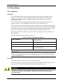
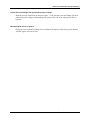
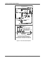
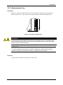
Wiring for immunity compliance
In applications where either the power, input or output wiring are subject to electromagnetic
disturbances, shielding techniques will be required. Grounded metal conduit with conductive
conduit fittings is recommended.
Connect the ac mains through a fused disconnect switch. To ensure that the unit meets the
immunity levels specified by EMC directive 89/336/EEC, install power line filter kit p/n 079163.
Wind three turns of each wire (14 AWG maximum) through the filter core for the two power and
protective earth leads as illustrated in Figure 4-1. The wound filter cores shall be located
external to the 9782 case within 25 cm.
28
9782 Series pH/ORP Analyzer/Controller - Operator’s Manual
3/00
Power Wiring
Conform to code
Instrument wiring should conform to regulations of the National Electrical Code.
4.3 Power Wiring Considerations
Recommended wire size
Observe all applicable electrical codes when making power connections. Unless locally
applicable codes dictate otherwise, use 14 gauge (2.081 mm2) wire for ac power, including
protective earth.
Power supply voltage and frequency within specs
The power supply voltage and frequency must be within the limits stated in the specifications in
Section 2.
Power for external preamp
The preamplifier power supply at terminals V+, V– and SC provides a nominal, unregulated +10
volts and –10 volts for an external preamp. If the 31022283 preamp is used, it will perform
correctly from this supply although its terminals are designated +16, –16 and SC.
3/00
9782 Series pH/ORP Analyzer/Controller - Operator’s Manual
29
Power Wiring
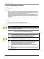
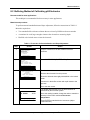
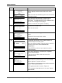
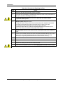
4.4 Installing Power Wiring
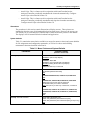
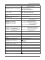
Procedure
Follow the procedure in Table 4-1 to install AC power wiring.
WARNING
Turn power off at mains before installing AC power wiring.
Table 4-1 Procedure for Installing AC Power Wiring
Step
1
Action
Check the tag on the outside of the case to be sure that the voltage rating of the unit
matches the input voltage at your site.
ATTENTION
The unit may be damaged if you apply power with the wrong voltage.
2
Open the case:
• Grasp the bottom center portion of the front bezel and pull it downward and toward you
slightly to disengage the bottom of the bezel from the edge of the case.
• Lift the bezel gently to disengage it from the top edge of the case.
• Swing the bezel to the left. (The bezel and display assembly is mounted on pivot arms.)
The safety cover with its warning label will be visible.
3
Remove the safety cover by removing the single screw holding it in place.
4
Install a fused disconnect switch in the power line which will be connected to the
Analyzer/Controller.
•If a 230/240 Vac line is to be connected, use a 0.125 amp fuse.
•If a 110/120 Vac line is to be connected, use a 0.25 amp fuse.
5
To ensure that the unit meets the immunity levels specified by EMC directive 89/336/EEC,
install power line filter supplied with Analyzer/Controller. Wind three turns of each wire (14
AWG maximum) through the filter core for the two power and protective earth leads as
illustrated in Figure 4-1. The wound filter cores shall be located external to the 9782 case
within 25 cm.
6
Connect the power wiring to terminals L1 and L2/N as shown in Figure 4-1. Connect the hot
side of the line to terminal L1 and the grounded side of the line to terminal L2/N.
If the L2/N side of the line cannot be grounded, add an isolating transformer electrically
between the power supply and the instrument and ground the L2/N terminal.
WARNING
The ground terminal (green screw) must be connected to a reliable earth ground for proper operation
and to comply with OSHA and other safety codes. If metal conduit is used, connect a bonding wire
between conduits. Do not rely upon the conductive coating of the instrument case to provide this
connection. Failure to observe this precaution may result in serious personal injury.
30
7
Replace the safety cover and secure it with the screw.
8
Close the case and power up the unit. Do not apply power until the case is closed.
9782 Series pH/ORP Analyzer/Controller - Operator’s Manual
3/00
Power Wiring
Power Terminations
L1
L2/N
PE
PE = Protective
Earth Ground
Figure 4-1 AC Power Terminals
3/00
9782 Series pH/ORP Analyzer/Controller - Operator’s Manual
31
Power Wiring
32
9782 Series pH/ORP Analyzer/Controller - Operator’s Manual
3/00
I/O Setup and System Configuration
5. I/O Setup and System Configuration
5.1 Overview
Introduction
This section provides instructions for performing I/O setup and for configuring the
Analyzer/Controller’s software to implement your control strategy.
What’s in this section?
The topics in this section are listed below.
Topic
See Page
5.1 Overview
33
5.2 I/O Setup and Configuration Tasks
34
5.3 Performing I/O Setup
39
5.4 Configuring Current Adjusting Type Control and/or Retransmission
of Process Variables
43
5.5 Configuring Duration Adjusting Type or Pulse Frequency Type Control
46
5.6 Configuring Alarms
50
5.7 Setting the Clock
51
5.8 Configuring AutoCal and AutoClean
52
Powering up the Analyzer/Controller
Every time the Analyzer/Controller is powered up the unit performs a “warm reset”. During a
warm reset, alarms are not cleared, and outputs are maintained at their last value prior to the loss
of power or initiation of the warm reset. A warm reset has no effect on configuration or
calibration values.
In addition to this warm reset, a “cold reset” function is available to return ALL configuration
values and some I/O setup values to the factory settings shown in Table 5-1. During a cold reset
the standardization offset is also returned to 0.0 and the percent theoretical slope is set back to
100.0, eliminating any changes made during manual or automatic calibration. All alarms will be
cleared. Analog outputs will go to zero momentarily, then go to the factory default values. A
cold reset can be initiated using a maintenance menu function as described in Section 10. It will
also be initiated during I/O setup if the input type is changed.
3/00
9782 Series pH/ORP Analyzer/Controller - Operator’s Manual
33
I/O Setup and System Configuration
5.2 I/O Setup and Configuration Tasks
Ease of configuration
Configuring the 9782 software is fast and easy. A menu is provided for every configuration task.
You will be permitted to configure only those parameters relevant to your application and
supported by the Analyzer/Controller model you purchased. In fact, configuration screens will
contain only prompts and menu choices that apply to your application.
Accessing the I/O setup and configuration menus
Use the MENU key to access the main menu which includes CONFIGURATION and I/O
SETUP choices.
If the security feature has been enabled as described in Section 10, the password must be entered
in response to the prompt before you can proceed. (Out-of-the-box units do not require entry of a
password to access the menu system.)
Purpose of I/O setup
I/O setup is the process of choosing the features to be used, so that the software can make
appropriate I/O assignments. I/O setup (see 5.3) must precede configuration. The choices made
during I/O setup determine which prompts and menu choices are available during configuration.
(Even though I/O setup is performed first, I/O SETUP is last on the main menu because you
usually only have to access this function once in the life of your Analyzer/Controller.)
Purpose of configuration menu items
The configuration menu contains the following items for accessing screens used to configure the
features described below.
34
•
CAT/RETRANSMISSION: If the hardware supports analog outputs, configure parameters
related to use of these outputs as described in 5.4. Output 1 and/or Output 2 can be used for
Current Adjusting Type (CAT) control. Any one, two or three outputs can be used for
retransmission of process variables. If the unit contains only one analog output, it can be
used for DualCAT (pH only); this feature controls two reagents using a single output
channel.
•
ALARMS: If one or more relays are available for annunciation of alarms, configure each
alarm setpoint, deadband, and delay as described in 5.6. (Action is configured with I/O
SETUP.)
•
DISCRETE CONTROL: One or more relays can be used to achieve control of process
variables using On/Off, Duration Adjusting Type (DAT) or Pulse Frequency Type (PFT)
control strategies. Configure the related parameter values as described in 5.5.
•
ADVANCED FEATURES: This menu item provides access to configuration screens for
the following features:
−
Clock Setup: A display showing the current time can be accessed when the unit is online.
The 24-hour clock must be set before you can use the AutoClean feature described
below. Set the clock as descibed in Section 5.7.
−
Auto Clean: AutoClean is a feature that lets the Analyzer/Controller periodically rinse
the electrodes automatically. Configure AutoClean as described in Section 5.8.
9782 Series pH/ORP Analyzer/Controller - Operator’s Manual
3/00
I/O Setup and System Configuration
−
AutoCal 1pt: This is a feature used in conjunction with AutoClean that lets the
Analyzer/Controller periodically standardize the electrodes automatically. Configure
AutoCal 1pt as described in Section 5.8.
−
AutoCal 2pt: This is a feature used in conjunction with AutoClean that lets the
Analyzer/Controller periodically standardize and slope the electrodes automatically.
Configure AutoCal 2pt as described in Section 5.8.
Illustrations
The procedures in this section contain illustrations of display screens. These pictures are
intended to show the types of information displayed on each screen. However, the screens you
will actually see on your Analyzer/Controller may be different from the pictures in the manual.
The displays will be customized for the hardware and application.
System defaults
Table 5-1 contains the menu choices available (or ranges for numeric values) and system defaults
for I/O assignments and configuration parameters, as well as for values entered during
maintenance functions described in Section 10.
Table 5-1 Menu Choices and System Defaults
PARAMETER
CHOICES or RANGE
(Default is underlined)
9782P-03
DURAFET (without Cap Adapter)
I/O setup: input 1
9782P-01, -02, or -04
DURAFET (not for Durafet with Cap Adapter)
GLASS (including Durafet with Cap Adapter)
ANTIMONY
ORP when ORP only is measured
9782P-03-R2 or 9782-03-R0
ALTELTRD [alternate electrode]
N/A
I/O setup: input 2
9782P-03-009782P-03-VC, 9782P-03-C2, 9782P-03-C3
N/A
9782P-01-R2, 9782P-01-R0, 9782P-02-R2, 9782-02-R0
ORP when both pH and ORP are measured
ALTELTRD when pH or ORP is measured
N/A when pH only or ORP only is measured, or Durafet is
used
9782P-01-00, 9782P-01-VC, 9782P-01-C2, 9782P-01-C3,
9782P-02-00, 9782P-02-VC, 9782P-02-C2, 9782P-02-C3,
ORP
N/A
I/O setup: automatic functions
3/00
ACLN ONLY [AutoClean only]
ACAL-1PT [AutoClean plus AutoCal one-point]
ACAL-2PT [AutoClean plus AutoCal two-point] (4 relays only)
N/A
9782 Series pH/ORP Analyzer/Controller - Operator’s Manual
35
I/O Setup and System Configuration
PARAMETER
I/O setup: discrete control type
CHOICES or RANGE
(Default is underlined)
two relays only
1PFT [pulse frequency type]
1DAT [duration adjusting type]
1O/F [on/off]
2PFT
2DAT
2O/F
ALM1 [alarm]
ALM2
ALM3
N/A
four relays - all of the above, plus
3O/F
4 O/F
I/O setup: analog output types
2CAT [DualCAT]
PCAT [CAT control based on pH measured value]
OCAT [CAT control based on ORP measured value]
pHCAT [retransmission of process pH value] default for
Output 1
ORPCAT [retransmission of process ORP value]
TEMPCAT [retransmission of process temperature value]
N/A default for Outputs 2 and 3
I/O setup: value alarmed or controlled
pH
TEMP
ORP
p/D [pH or self-diagnostic]
T/D [temperature or self-diagnostic]
O/D [ORP or self-diagnostic]
N/A
I/O setup: alarm associated with relay (two relay
units only; one-to-one correspondence between
relay and alarm is fixed when four alarms are
available)
ALM1 [alarm 1] default for Relay 1
ALM2 [alarm 2] default for Relay 2
ALM3 [alarm 3]
ALM1/2 [alarm 1 and/or 2]
ALM4 [alarm 4]
N/A
I/O setup: relay alarm action
HIGH [high alarm] default for Relay 1 and Relay 3
LOW [low alarm] default for Relay 2 and Relay 4
N/A
configuration: retransmission 0 %
pH: –2.00 to 14.00, default = 0
ORP: –1999 to +1999 mV, default = 0
TEMP: –10 to 140 ± 1 °C, default = 0
configuration: retransmission 100 %
pH: –2.00 to 14.00, default = 14.00
ORP: –1999 to +1999 mV, default = 1999
TEMP: –10 to 140 ± 1 °C, default = 140
configuration: CAT/retransmission failover usage
(only available with VC or RO output options)
DISABLED
ENABLED
configuration: CAT/retransmission failover value
(only available with VC or RO output options and
when Failover ENABLED)
pH: –2.00 to 14.00, default = 14.00
ORP: –1999 to +1999 mV, default = 1999
36
9782 Series pH/ORP Analyzer/Controller - Operator’s Manual
3/00
I/O Setup and System Configuration
PARAMETER
CHOICES or RANGE
(Default is underlined)
configuration: standard CAT 1 or CAT 2 setpoint
pH: –2.00 to 14.00, default = 0
ORP: –1999 to +1999 mV, default = 0
TEMP: –10 to 140 ± 1 °C, default = 0
configuration: standard CAT 1 or CAT 2
proportional band limit
pH: –2.00 to 14.00, default = 14.00
ORP: –1999 to +1999 mV, default = 1999
TEMP: –10 to 140 ± 1 °C, default = 140
configuration: DualCAT pH CAT1 or CAT 2
setpoint
–2.00 to 14.00, default = 0
configuration: DualCAT pH CAT1 or CAT 2
proportional band limit
–2.00 to 14.00, default = 14
configuration: DualCAT pH switchover value
–2.00 to 14.00, default = 0 for Relays 2 and 4;
14.00 for Relays 1 and 3
configuration: alarm setpoint value
configuration: cycle timer setpoint
configuration: PFT control setpoint
configuration: DAT control setpoint
pH: –19.99 to 19.99, default = 0 for Relays 2 and 4;
14.00 for Relays 1 and 3
ORP: –1999 to +1999 mV, default = 0 for Relays 2
and 4; 1999 for Relays 1 and 3
TEMP: 1 to 100 °C, default = 0 for Relays 2 and 4;
140 for Relays 1 and 3
configuration: alarm deadband value
configuration: cycle timer deadband upper limit
configuration: PFT control proportional band limit
(pH and ORP only)
configuration: DAT control proportional band limit
(pH and ORP only)
pH: –0.01 to 19.99, default = 0.01 for Relays 1 and 2;
setpoint default for Relays 3 and 4
ORP: –1999 to +1999 mV, default = 1 for Relays 1 and 2;
setpoint default for Relays 3 and 4
TEMP: 1 to 100 °C, default = 1 for Relays 1 and 2;
N/A for Relays 3 and 4
configuration: alarm delay
0 to 100 seconds, default = 0
configuration: cycle timer period
1 to 1000 seconds, default = 60
configuration: cycle timer “on” time
0 to 100 % at 1 % resolution, default = 100
configuration: PFT control maximum pulse
frequency
1 to 200 pulses/second, default = 60
configuration: DAT control cycle period
1 to 200 seconds, default = 15
configuration: 24-hour clock set mode
OFF
ON W/ RESET
ON W/O RESET
configuration: 24-hour clock set hour
0-23, default = 00
configuration: 24-hour clock set minute
0-59, default = 0X
configuration: AutoCal/AutoClean timer days
0 to 28, default = 0
configuration: AutoCal/AutoClean timer hours
0 to 23, default = 1
configuration: AutoCal/AutoClean timer minutes
0 to 59, default = 0
configuration: AutoCal/AutoClean rinse duration
1 to 1999 seconds, default = 60
configuration: AutoCal/AutoClean output hold
YES
NO
3/00
9782 Series pH/ORP Analyzer/Controller - Operator’s Manual
37
I/O Setup and System Configuration
PARAMETER
CHOICES or RANGE
(Default is underlined)
configuration:AutoCal/AutoClean buffer flow
duration
1 to 1999 seconds, default = 200
configuration: AutoCal/Clean resume delay
1 to 1999 seconds, default = 60
configuration: AutoCal/AutoClean number between
operations
1 to 1999 occurences, default = 1
maintenance: enable security
NO
YES
maintenance: password
0000 to 9999; default = 0000
maintenance: solution temperature compensation
type
PURE WATER
AMMONIA
PHOSPHATE
MORPHALINE
OTHER
N/A
maintenance: solution temperature compensation
value
for PURE WATER = - 0.16
for AMMONIA = - 0.32
for PHOSPHATE = - 0.32
for MORPHALINE = - 0.32
for N/A = 0
maintenance: Durafet temperature display
ON
OFF
maintenance: electrode selection
PRIMARY
ALTERNATE
maintenance: relay activation on alarm/control
ENERGIZE
DE-ENERGIZE
38
9782 Series pH/ORP Analyzer/Controller - Operator’s Manual
3/00
I/O Setup and System Configuration
5.3 Performing I/O Setup
Purpose
Before you can configure your Analyzer/Controller to implement your control strategy you must
perform I/O setup. In I/O setup you choose the features to be used, based on the hardware
capability of the 9782 model being configured. Using your selections, the software will display
the relay and analog output assignments appropriate for your application. The choices made
during I/O setup determine which prompts and menu choices are available during configuration.
For a discussion of the features available, and of the priority scheme used to assign relays, see
Section 1.
ATTENTION
If you add an option card to the 9782, it is very important that you change the model
number stored in memory (see Section 10).
During I/O setup the software will display prompts only for those features the hardware
can support. The model number of the unit was stored in the 9782 memory at the factory.
Each combination of features has a unique model number (see Section 2). Therefore, the
processor can use this information to determine which prompts and selections are
appropriate.
Entering the new number when you modify the hardware will let the processor know
about the new hardware capabilities. As a result, you will be able to configure the unit to
take advantage of features requiring that hardware.
Procedure
The procedure for I/O setup configuration is shown in Table 5-2.
3/00
9782 Series pH/ORP Analyzer/Controller - Operator’s Manual
39
I/O Setup and System Configuration
Table 5-2 Procedure for Performing I/O Setup
Step
1
Screen
Action
Go to I/O SETUP.
0(18
&21),*85$7,21
&$/,%5$7,21
0$,17(1$1&(
,26(783
',$*1267,&6
1(;7
2
RELAY SETTINGS
RLY1 RLY2 RLY3
N/A N/A pH
ACLN ACAL HIGH
N/A N/A ALM3
DIAGNOSTICS
| PREV |
RLY4
TEMP
LOW
ALM4
NEXT
The first screen shows the present use of available relays.
This information is read-only.
In this example the 9782 has four relays. Relay 1 and
Relay 2 are used for AutoClean and one-point AutoCal
(standardization). Relay 3 is used to trigger an
annunciator if process variable pH goes over the alarm
setpoint. Relay 4 is used for a low alarm on the
temperature value.
If the 9782 has only two relays, the screen will show Relay
1 twice. This permits display of alarm assignments even
in the case where two alarms are assigned to Relay 1.
Go to the next screen.
3
ANALOG OUTPUTS
OUTPUT 1:
OUTPUT 2:
OUTPUT 3:
pH
pH
TEMP
DIAGNOSTICS
| PREV | NEXT
4
ATTENTION:
ANY RECONFIGURATION
CAN AFFECT OTHER
PARAMETERS!
The next screen shows the present assignments for the
optional current or voltage outputs, if available. This
information is read-only.
Go to the next screen.
I/O setup is performed only once, before field connections
are made to the Analyzer/Controller.
Go to the next screen.
DIAGNOSTICS
| PREV | NEXT
5
1
6(/(&7,13877<3(
,1387'85$)(7
,13871$
',$*1267,&6
Specify the type of input(s) to be used.
NOTE: Set INPUT1 to "GLASS" if using Durafet II
electrode with Cap Adapter. For regular Durafet with
external or internal preamp input set to "DURAFET".
1(;7
If you specify any inputs other than the defaults, the unit
will immediately perform a cold reset, returning all
configuration and calibration values to the factory defaults.
A cold reset will also return some I/O setup values to
factory settings. If you change the input type, be sure
to cycle through all the other I/O setup screens and
check that the settings are appropriate for your
application.
Go to the next screen.
40
9782 Series pH/ORP Analyzer/Controller - Operator’s Manual
3/00
I/O Setup and System Configuration
Step
6
Screen
$8720$7,&)81&7,216
Specify the automatic functions to be used.
Note that if AutoCal is used, AutoClean is always also
used, too.
6(/(&7$&$/37
',$*1267,&6
1(;7
7
Action
',6&5(7(&21752/
6(/(&73)7
',$*1267,&6
Go to the next screen.
If discrete control using relays is planned, enter the control
type (ON/OFF with cycle timers, Pulse Frequency Type or
Duration Adjusting Type).
Go to the next screen.
1(;7
8
$1$/2*2873876
287387S+
287387253
2873877(03
',$*1267,&6
1(;7
If the hardware supports analog outputs, specify which
process variables will be retransmitted (pH, ORP, or
TEMP) or used for Current Adjusting Type control using an
output signal that is directly proportional to the input signal
(PCAT for pH and OCAT for ORP).
• Any output can be used for retransmission.
• Only Outputs 1 and 2 can be used for CAT control.
• A unit having only one output can use it for
retransmission, CAT control of a single variable, or
DualCAT control of two reagents.
Go to the next screen.
9
&21752/$/$50,13876
$/0S+
3)7S+
If you specified a type of discrete control earlier, use this
screen to specify the process variables (inputs) on which
the control action will be based.
$/0253
$/07(03
',$*1267,&6
1(;7
If you have any relays left for alarms, use this screen to
specify what will be alarmed. (Whether relays energize or
de-energize on alarm is configurable using the
Maintenance Menu; see Section 10.)
Go to the next screen.
10
7:25(/$<6$9$,/$%/(
)25$/$50$66,*10(17
5/<5/<
$$/0
',$*1267,&6
1(;7
If the unit has only two relays, and none are being used for
AutoClean, AutoCal, or discrete control, then a screen is
available for assigning alarms to relays. (A parallel screen
is never displayed for units with four relays because the
mapping of an alarm to an available relay is fixed.)
Go to the next screen.
11
&21752/$/$50$&7,21
5/<5/<5/<5/<
S+S+2537(03
This screen shows the control or alarm input, and alarm
number (if applicable) associated with each relay using
earlier screens.
$/03)7$/0$/0
+,*+1$/2:+,*+
',$*1267,&6
1(;7
Use this screen to configure the action (high or low)
associated with each alarm. Note that relays assignments
for discrete control, AutoClean, and AutoCal cannot be
changed here.
Go to the next screen.
3/00
9782 Series pH/ORP Analyzer/Controller - Operator’s Manual
41
I/O Setup and System Configuration
Step
12
Screen
1(:5(/$<6(77,1*6
5/<5/<5/<5/<
S+S+2537(03
Action
The screen will display the new relay assignments,
reflecting the choices you made earlier. This information
is read-only.
$/03)7$/0$/0
+,*+1$/2:+,*+
',$*1267,&6
1(;7
Make a note of it so that you can wire the relay terminals
correctly (see Section 6).
Go to the next screen.
13
1(:
$1$/2*2873876
287387S+
287387253
The screen will display the new current or voltage output
assignments, reflecting the choices you made earlier. This
information is read-only.
2873877(03
',$*1267,&6
1(;7
Make a note of it so that you can wire the output terminals
correctly (see Section 6).
Go to the next screen.
14
(17(572&217,18(
Pressing ENTER will do a warm reset and will also store
these changes in memory, overwriting any previous I/O
setup.
',$*1267,&6
1(;7
15
35(66(17(572
Press ENTER again to complete the operation and return
the display to the main menu.
5(7851720$,10(18
',$*1267,&6
1(;7
1
For Durafet II electrodes with a standard preamp input, if you want to display process temperature, or take
advantage of the Durafet electrode’s ability to compensate for pH changes in a solution due to temperature
changes, then a separate temperature input is required. It is not specified here, because temperature input uses
special input terminals. However, the temperature input must be wired as shown in section 6. In addition, to
use the solution temperature compensation feature, a solution temperature coefficient must be entered as
described in section 10.
For Durafet II electrodes with a Cap Adapter, a separate temperature sensor is not required.
42
9782 Series pH/ORP Analyzer/Controller - Operator’s Manual
3/00
I/O Setup and System Configuration
5.4 Configuring Current Adjusting Type (CAT) Control and/or
Retransmission of Process Variables
Purpose
If the hardware supports analog outputs, during I/O setup you had an opportunity to specify
which process variables will be retransmitted, or used as the basis for DualCAT or CAT control.
(The DualCAT feature permits control of pH with two reagents alternately using a single output,
as described in Section 1.) Before using an analog output for retransmission or control, you must
configure the related parameter values.
Regardless of whether you plan to retransmit a process value to a recorder or control a device
based on that value, the output signal will be directly proportional to the input. However, the
configuration screens are different for the different output uses.
For a discussion of tuning proportional control see Appendix E.
Procedure
The procedure for configuring CAT control and/or retransmission of process variables is shown
in Table 5-3.
Hold mode
To place the unit in Hold mode before configuring CAT control, go to an online display screen
and press the HOLD soft key. To take the unit out of Hold mode after configuration, go back to
an online screen and press the HOLD soft key again.
3/00
9782 Series pH/ORP Analyzer/Controller - Operator’s Manual
43
I/O Setup and System Configuration
Table 5-3 Procedure for Configuring CAT Control and/or Retransmission of
Process Variables
Step
1
Screen
MENU
CONFIGURATION
CALIBRATION
MAINTENANCE
I/O SETUP
Action
Go to CONFIGURATION | CAT/RETRANSMISSION.
DIAGNOSTICS
| PREV | NEXT
CONFIGURATION
CAT/RETRANSMISSION
ALARMS
DISCRETE CONTROL
AUTO CAL/CLEAN
ATTENTION: Any value entered for one of these
parameters will take effect as soon as it is entered
UNLESS THE 9782 IS IN HOLD MODE.
DIAGNOSTICS
|
|
2
CAT/RETRANSMISSION
OUTPUT 1
CAT 2
OUTPUT 3
DIAGNOSTICS
|
|
CAT/RETRANSMISSION
DUAL CAT
DIAGNOSTICS
|
|
What configurable items are displayed depends on what
analog output type was specified during I/O setup.
• A retransmitted variable will be indicated here as
“OUTPUT n”.
• CAT based on pH (PCAT) or ORP (OCAT) will be
indicated here as “CAT n”.
• DualCAT (2CAT) is only available if the unit has only one
analog output, so this choice is always displayed alone.
Select the output to be configured.
CAT/RETRANSMISSION
DE ENABLED
DIAGNOSTICS
|
|
3
OUTPUT e
INPUT
pH
0%
1 pH
100%
7 pH
FAILOVER:
ENABLE
FAILOVER VAL:
9 pH
DIAGNOSTICS
HOLD| <
|
>
For each output to which a retransmitted process variable
was assigned during I/O setup, the PV will be displayed,
and the appropriate unit of measure will be filled in. (This
is read-only information.)
Specify the range by entering the values to be represented
by outputs of 0 % and 100 %. If reverse-acting output is
required, enter the high range value at the 0 % prompt and
the low range value at the 100 % prompt.
For output options VC or RO the FAILOVER feature is
available. If failover is enabled here, then when the unit’s
self-diagnostics find a malfunction, the output will go the
failover value entered on this screen. When FAILOVER is
ENABLED or DISABLED the 0 and 100% values are
changed back to factory defaults.
44
9782 Series pH/ORP Analyzer/Controller - Operator’s Manual
3/00
I/O Setup and System Configuration
Step
Screen
4
DUALCAT pH
CAT1 SP:
7 pH
CAT1 PB:
2 pH
CAT2 SP:
7 pH
CAT2 PB:
14 pH
SWITCHOVRRLY:
7 pH
DIAGNOSTICS
| <--- | --->
5
CAT 2
INPUT:
CAT2 SP:
CAT2 PB:
pH
7 pH
1.5 pH
DIAGNOSTICS
| <--- | --->
6
3/00
Action
If DualCAT is used, specify the range for control of each
reagent.
Enter the value at which the output switchover must occur.
For each output to which a CAT based on pH or ORP was
assigned during I/O setup, the PV will be displayed, and
the appropriate unit of measure will be filled in. (This is
read-only information.)
Specify the setpoint and proportional band limit.
When all output parameters have been configured, take
the unit out of Hold mode.
9782 Series pH/ORP Analyzer/Controller - Operator’s Manual
45
I/O Setup and System Configuration
5.5 Configuring On/Off, Duration Adjusting Type (DAT), or
Pulse Frequency Type (PFT) Control
Purpose
During I/O setup you had an opportunity to specify whether to use one or more relays to achieve
control of a process variable with a discrete control strategy: On/Off, DAT or PFT.
If one of these control types was selected, you will be able to configure the related parameter
values.
For a discussion of tuning proportional control (applicable to PFT and DAT control) see
Appendix E.
Procedure
The procedure for configuring On/Off control is shown in Table 5-4.
The procedure for configuring PFT control is shown in Table 5-5.
The procedure for configuring DAT control is shown in Table 5-6.
46
9782 Series pH/ORP Analyzer/Controller - Operator’s Manual
3/00
I/O Setup and System Configuration
Table 5-4 Procedure for Configuring On/Off Control
Step
1
Screen
Action
MENU
CONFIGURATION
CALIBRATION
MAINTENANCE
I/O SETUP
Go to CONFIGURATION | DISCRETE CONTROL |
ON/OFF.
DIAGNOSTICS
| PREV | NEXT
CONFIGURATION
CAT/RETRANSMISSION
ALARMS
DISCRETE CONTROL
AUTO CAL/CLEAN
ATTENTION: Any value entered for one of these controlrelated parameters will take effect as soon as it is entered
UNLESS THE 9782 IS IN HOLD MODE.
DIAGNOSTICS
|
|
DISCRETE CONTROL
ON/OFF
PFT
DAT
DIAGNOSTICS
|
|
2
3
ON/OFF CONTROL
CYCLE PERIOD: 100 s
CYCLE TMR 1
CYCLE TMR 2
CYCLE TMR 3
CYCLE TMR 4
DIAGNOSTICS
|
|
Use this screen to specify the length of the cycle period for
all timers.
To configure an individual timer associated with one of the
relays, select it from the menu.
The input type, relay assignment and appropriate relay
output action will already be filled in, based on the process
variable assigned to this On/Off control output during I/O
setup. (This is read-only information.)
212))&<&/(7,0(5H
,1387S+
2873875/<
6(732,17S+
'($'%$1'S+
217,0(
',$*1267,&6
+2/'
!
Enter the setpoint at which the output should be turned on.
If desired, specify a deadband limit. (If the PV varies from
the setpoint while the output is ON, but by less than the
value of the deadband limit, the output will remain on.)
Enter the percent of the cycle period that the relay should
stay on when the setpoint is reached.
Take the unit out of Hold mode.
3/00
9782 Series pH/ORP Analyzer/Controller - Operator’s Manual
47
I/O Setup and System Configuration
Table 5-5 Procedure for Configuring PFT Control
Step
1
Screen
Action
MENU
CONFIGURATION
CALIBRATION
MAINTENANCE
I/O SETUP
Go to CONFIGURATION | DISCRETE CONTROL | PFT.
DIAGNOSTICS
| PREV | NEXT
CONFIGURATION
CAT/RETRANSMISSION
ALARMS
DISCRETE CONTROL
AUTO CAL/CLEAN
ATTENTION: Any value entered for one of these controlrelated parameters will take effect as soon as it is entered
UNLESS THE 9782 IS IN HOLD MODE.
DIAGNOSTICS
|
|
DISCRETE CONTROL
ON/OFF
PFT
DAT
DIAGNOSTICS
|
|
2
PFT CONTROL
PFT1
PFT2
Use this screen to select the PFT control output to be
configured.
DIAGNOSTICS
HOLD |
|NEXT
3
3)7
,1387S+
2873875/<
6(732,17S+
3%/,0,7S+
The input type, relay assignment and appropriate unit of
measure will already be filled in, based on the process
variable assigned to this PFT control output during I/O
setup. (This is read-only information.)
3%)5(45$7(+]
',$*1267,&6
+2/'
!
Enter the setpoint at which the output should be turned on.
Enter the PB Limit. This is the value for which the output’s
pulse output rate will be at its maximum frequency.
Specify the maximum frequency rate representing 100%
output. (Be sure this rate is compatible with the controlled
device.) The rate specified for the last PFT control
output configured will apply to all PFT outputs.
Take the unit out of Hold mode.
48
9782 Series pH/ORP Analyzer/Controller - Operator’s Manual
3/00
I/O Setup and System Configuration
Table 5-6 Procedure for Configuring DAT Control
Step
1
Screen
Action
MENU
CONFIGURATION
CALIBRATION
MAINTENANCE
I/O SETUP
Go to CONFIGURATION | DISCRETE CONTROL | DAT.
DIAGNOSTICS
| PREV | NEXT
CONFIGURATION
CAT/RETRANSMISSION
ALARMS
DISCRETE CONTROL
AUTO CAL/CLEAN
ATTENTION: Any value entered for one of these controlrelated parameters will take effect as soon as it is entered
UNLESS THE 9782 IS IN HOLD MODE.
DIAGNOSTICS
|
|
DISCRETE CONTROL
ON/OFF
PFT
DAT
DIAGNOSTICS
|
|
2
DAT CONTROL
DAT1
DAT2
Use this screen to select the DAT control output to be
configured.
DIAGNOSTICS
HOLD |
|NEXT
3
'$7
,1387S+
2873875/<
6(732,17S+
3%/,0,7S+
&<&/(3(5,2'+]
The input type, relay assignment and appropriate unit of
measure will already be filled in, based on the process
variable assigned to this DAT control point during I/O
setup. (This is read-only information.)
',$*1267,&6
+2/'
!
Enter the setpoint at which the output should be turned on.
Enter the PB Limit. This is the value for which the output’s
on duration will be maximum.
Specify the length of the cycle period (in seconds) for the
time-proportioned control. The cycle period specified
for the last DAT control output configured will apply to
all DAT outputs.
Take the unit out of Hold mode.
3/00
9782 Series pH/ORP Analyzer/Controller - Operator’s Manual
49
I/O Setup and System Configuration
5.6 Configuring Alarms
Purpose
If you configured input and action for one or more alarms during I/O setup (described in 5.3),
configure each alarm’s setpoint, deadband, and delay as described below.
Procedure
The procedure for configuring parameters for an alarm is described in Table 5-7.
Table 5-7 Procedure for Configuring Alarms
Step
1
Screen
Action
MENU
CONFIGURATION
CALIBRATION
MAINTENANCE
I/O SETUP
Go to CONFIGURATION | ALARMS | ALARM e.
DIAGNOSTICS
| PREV | NEXT
CONFIGURATION
CAT/RETRANSMISSION
ALARMS
DISCRETE CONTROL
AUTO CAL/CLEAN
ATTENTION: Any value entered for one of these alarmrelated parameters will take effect as soon as it is entered
UNLESS THE 9782 IS IN HOLD MODE.
DIAGNOSTICS
|
|
ALARMS
DELAY
ALARM 1
ALARM 2
ALARM 3
ALARM 4
DIAGNOSTICS
|
|
2
5S
Select the appropriate alarm for configuration.
$/$50H
,1387S+
$/$50+,*+
'(/$<6
6(732,17S+
'($'%$1'S+
',$*1267,&6
+2/'
Enter a delay value to prevent brief upsets from activating
an alarm. This configured delay value will apply to all
alarms.
!
The process variable and action configured for the alarm
during I/O setup will be displayed. The delay time in
seconds configured under ALARMS will also be displayed.
Enter the setpoint value at which the alarm will become
active.
Specify the deadband. Once the alarm is active, it will not
deactivate until the PV differs from the setpoint by at least
the value of the deadband limit.
Take the unit out of Hold mode.
50
9782 Series pH/ORP Analyzer/Controller - Operator’s Manual
3/00
I/O Setup and System Configuration
5.7 Setting the Clock
Purpose
A display showing the current time can be accessed when the unit is online. The 24-hour clock
must be set before you can use the AutoClean feature described in Subsection 5.8.
Procedure
Follow the procedure in Table 5-8 to set the 24-hour clock.
Table 5-8 Procedure for Setting the Clock
Step
1
Screen
MENU
CONFIGURATION
CALIBRATION
MAINTENANCE
I/O SETUP
Action
Go to CONFIGURATION | ADVANCED FEATURES |
CLOCK SETUP.
DIAGNOSTICS
| PREV | NEXT
&21),*85$7,21
&$75(75$160,66,21
$/$506
',6&5(7(&21752/
$'9$1&(')($785(6
',$*1267,&6
35(9
1(;7
$'9$1&(')($785(6
&/2&.6(783
$872&/($1
',$*1267,&6
2
AUTO CLEAN
CLOCK SETUP:
CLOCK
ON W/RESET
HOURS
13
MINUTES
30
DIAGNOSTICS
|
| NEXT
Set the clock. For example, if you will start the clock at
1:30 PM, enter 13 hours, 30 minutes.
Start the clock and specify what should happen to the
clock if the power fails.
• ON W/RESET starts the clock now. Following power
failure, the clock will be reset to 00:00 and the diagnostic
message “RESET CLOCK” will be displayed.
• ON W/O RESET starts the clock now. Following power
failure the clock will remain off, and the diagnostic
message “RESET CLOCK” will be displayed.
Display of “RESET CLOCK” will continue until you either
reset the clock or turn it off.
3/00
9782 Series pH/ORP Analyzer/Controller - Operator’s Manual
51
I/O Setup and System Configuration
5.8 Configuring AutoCal and AutoClean
Purpose
Periodic calibration of electrodes is necessary for best system performance because electrode
outputs change over time. One-point calibration (standardization) is a zero adjustment to
compensate for electrode drift. Two-point calibration (standardization and slope adjustment)
includes a span adjustment to match the gain of the Analyzer/Controller to the electrode
response. Standardization and slope each depend on the electrode measuring a reference solution
(buffer) of known pH.
The AutoCal and AutoClean features periodically rinse and calibrate electrodes automatically
(see Section 7). If these features were selected during I/O setup (described in 5.3), configure
control of AutoCal and AutoClean as described below. (If manual calibration will be used
instead, see Section 8.)
AutoCal and AutoClean configuration consists of setting the clock, and specifying the frequency
and duration of the cleaning and calibration operations.
ATTENTION
For Auto Clean/Cal to operate, the 24-hour clock must be set as described in 5.7.
The piping and valves required by AutoCal and AutoClean are shown in Section 7.
Timer-initiated operation
With the 24-hour clock turned ON and the AutoClean feature enabled (and the appropriate piping
in place), this mode performs unassisted cell cleaning. The AutoClean Time Remaining on-line
display provides an up-to-date time stamp of the next occurrence of an automatic cell cleaning.
Once the timer reaches zero, the cell cleaning will occur. Upon completion, the timer will be
reset and the Time Remaining display will again provide a countdown to the next cleaning. To
temporarily disable timer-initiated AutoClean, you must either turn off the 24-hour clock (which
preserves your timer setup), or set the timer to all zeros (see Step 2 in Table 5-9). Unless the
Time Remaing display is on screen, you will not see the AUTO CLEAN message during a
scheduled cleaning.
Operator-initiated operation
To operate in this mode, you must have the AutoClean Time Remaining display on screen.
Initiate the AutoClean sequence by pressing the START soft key. Once the START soft key is
pushed, the time display will go to zero and the message “AUTO CLEAN” will appear on the
alarm stripe.
The sequence will stop cleaning if the STOP soft key is pressed or if you leave this display. Once
stopped, the Analyzer/Controller will wait for the configured resume delay time (to allow the cell
measurement to stabilize) before coming back on-line. During the resume the “AUTO CLEAN”
message will flash.
If the PAUSE soft key is used while the AutoClean Time Remaing display is on screen, the
AutoClean sequence will stop temporarily. If the PAUSE soft key is not pushed again to resume
the sequence, then the sequence will automatically resume in 20 minutes.
52
9782 Series pH/ORP Analyzer/Controller - Operator’s Manual
3/00
I/O Setup and System Configuration
Once the AutoClean sequence has been completed (including resume delay), the “AUTO
CLEAN” message disappears and the time remaining clock will be displayed again, showing the
time remaining until the next scheduled timer-initiated cleaning.
ATTENTION
Once an AUTOSEQUENCE is initiated you cannot go into the menu displays until
sequence is completed. If you do, sequence will stop.
Hold mode
During AutoClean and AutoCal operations alarms are always held. This means that no alarms
will become active during the automatic operation. If one or more relays are being used for
alarm annunciation, they will go to the non-alarm state.
The behavior of analog outputs and discrete control relays during automatic operations is
configurable. The outputs can either be held at their current value or state when the operation
starts, or they can continue to respond to input changes during the automatic operation.
ATTENTION
The alarm stripe will display “HOLD ACTIVE.”
At the completion of the automatic operation the hold will be released and normal operation will
resume after the configured delay.
Procedure
If only AutoClean was selected during I/O setup, follow the procedure in Table 5-9 to use the
displayed screens for configuration when AUTO CAL/CLEAN is selected from the menu.
If one-point AutoCal (standardization only) was selected during I/O setup, follow the procedure
in Table 5-10.
If two-point AutoCal (standardization and slope adjustment) was selected during I/O setup,
follow the procedure in Table 5-11.
3/00
9782 Series pH/ORP Analyzer/Controller - Operator’s Manual
53
I/O Setup and System Configuration
Table 5-9 Procedure for Configuring AutoClean
Step
1
Screen
MENU
CONFIGURATION
CALIBRATION
MAINTENANCE
I/O SETUP
Action
Go to CONFIGURATION | ADVANCED FEATURES |
AUTO CLEAN.
DIAGNOSTICS
| PREV | NEXT
&21),*85$7,21
&$75(75$160,66,21
$/$506
',6&5(7(&21752/
$'9$1&(')($785(6
',$*1267,&6
35(9
1(;7
$'9$1&(')($785(6
&/2&.6(783
$872&/($1
',$*1267,&6
35(9
2
1(;7
Timer setup is used to specify the frequency of the rinses.
$872&/($1
7,0(56(783
'$<6
+2856
0,187(6
• If several rinses are to be performed in a single day
a) specify the number of days as zero
&855(17'$<
',$*1267,&6
+2/'
b) specify the number of hours and minutes in the
interval between rinses.
• If rinses are to occur at intervals of days
a) specify the number of days in the interval
b) specify the time of day (hours and minutes) the
rinse should occur.
In our example, the rinse will occur every third day at
4:30 PM.
• If you plan to use AutoClean/Cal, but initiate rinses
manually using the real time AutoClean/Cal Time
Remaining display:
a) specify the number of days as zero
b) specify the number of hours and minutes in the
interval between rinses as zero also.
IF YOU ENTER ALL ZEROS, NO AUTOMATIC
RINSES WILL BE PERFORMED.
Specify where today falls in the AutoClean cycle. For
example, if the interval for rinses is 3 days and you want
the first rinse to be tomorrow, specify that today is day 2.
3
$872&/($1
Enter the duration of the rinse (in seconds).
5,16(6(783
'85$7,21
5(680('(/$<
',$*1267,&6
35(9
54
Enter the number of seconds the Analyzer/Controller
should wait after the rinse before resuming normal
operation.
1(;7
9782 Series pH/ORP Analyzer/Controller - Operator’s Manual
3/00
I/O Setup and System Configuration
Table 5-10 Procedure for Configuring One-Point AutoCal
Step
1
Screen
Action
MENU
CONFIGURATION
CALIBRATION
MAINTENANCE
I/O SETUP
Go to CONFIGURATION | AUTOCAL/CLEAN.
DIAGNOSTICS
| PREV | NEXT
&21),*85$7,21
&$75(75$160,66,21
$/$506
',6&5(7(&21752/
$'9$1&(')($785(6
',$*1267,&6
$'9$1&(')($785(6
&/2&.6(783
$872&$/37
',$*1267,&6
1(;7
2
AUTO CAL 1PT
ATTENTION!
FUNCTION REQUIRES
AUTO BUFFER SETUP IN
CALIBRATION MENU
Buffer specification is described in Table 8-6.
Go to the next screen.
DIAGNOSTICS
HOLD |
|NEXT
3
AUTO CAL 1PT
HOLD OUTPUTS?
YES
DIAGNOSTICS
|
| NEXT
3/00
Specify whether or not output values should be held during
the automatic operations. Alarms are always held and for
that reason “HOLD ACTIVE” will appear on the alarm
stripe.
Go to the next screen.
9782 Series pH/ORP Analyzer/Controller - Operator’s Manual
55
I/O Setup and System Configuration
Step
4
Screen
Action
AUTO CAL 1PT
TIMER SETUP
DAYS
3
HOURS
16
MINUTES
30
CURRENT DAY
2
DIAGNOSTICS
|
| NEXT
Timer setup is used to specify the frequency of the
AutoClean rinses that are included in the AutoCal
schedule.
• If several rinses are to be performed in a single day:
a) specify the number of days as zero
b) specify the number of hours and minutes in the
interval between rinses (1 hour is the minimum).
• If rinses are to occur at intervals of days:
a) specify the number of days in the interval
b) specify the time of day (hours and minutes) the
rinse should occur.
In our example, the rinse will occur every third day at
4:30 PM.
• If you plan to use AutoCal, but initiate operations
manually using the real time AUTOCAL/CLEAN display:
a) specify the number of days as zero
b) specify the number of hours and minutes in the
interval between rinses as zero also.
IF YOU ENTER ALL ZEROS, NO AUTOMATIC
RINSES AND NO AUTOMATIC CALIBRATIONS
WILL BE PERFORMED.
Specify where today falls in the AutoCal/AutoClean cycle.
For example, if the interval for rinses is 3 days and you
want the first rinse to be tomorrow, specify that today is
day 2.
Go to the next screen.
5
AUTO CAL 1PT
RINSE SETUP:
DURATION
#BETWEEN STD
180s
2
DIAGNOSTICS
|
| NEXT
Enter the duration of the AutoClean rinse in seconds (60 is
the minimum).
Specify the frequency of AutoCal standardization
operations by entering the number of rinses between
standardization operations. In our example, timer setup
was configured for rinses to be done every third day. If,
during rinse setup, two rinses are scheduled to occur
between standardization operations, then the one-point
AutoCal standardization will be performed every sixth day.
Go to the next screen.
6
AUTO CAL 1PT
STANDARDIZE SETUP:
DURATION
70s
DELAY
90s
DIAGNOSTICS
|
| NEXT
56
Enter the length of time in seconds (60 is the minimum).
The standardization reference solution should flow past
the electrode.
Enter the number of seconds the Analyzer/Controller
should wait after the AutoCal operation before resuming
normal operation.
9782 Series pH/ORP Analyzer/Controller - Operator’s Manual
3/00
I/O Setup and System Configuration
Table 5-11 Procedure for Configuring Two-Point AutoCal
Step
1
Screen
Action
MENU
CONFIGURATION
CALIBRATION
MAINTENANCE
I/O SETUP
Go to CONFIGURATION | AUTOCAL/CLEAN.
DIAGNOSTICS
| PREV | NEXT
&21),*85$7,21
&$75(75$160,66,21
$/$506
',6&5(7(&21752/
$'9$1&(')($785(6
',$*1267,&6
$'9$1&(')($785(6
&/2&.6(783
$872&$/37
',$*1267,&6
1(;7
2
AUTO CAL 2PT
ATTENTION
FUNCTION REQUIRES
AUTO BUFFER SETUP IN
CALIBRATION MENU
Buffer specification is described in Table 8-6.
Go to the next screen.
DIAGNOSTICS
|
|NEXT
3
AUTO CAL 2PT
HOLD OUTPUTS?
YES
DIAGNOSTICS
|
|NEXT
3/00
Specify whether or not output values should be held during
the automatic operations. Alarms are always held and for
that reason “HOLD ACTIVE” will appear on the alarm
stripe.
Go to the next screen.
9782 Series pH/ORP Analyzer/Controller - Operator’s Manual
57
I/O Setup and System Configuration
Step
4
Screen
Action
AUTO CAL 2PT
TIMER SETUP
DAYS
3
HOURS
16
MINUTES
30
CURRENT DAY
2
DIAGNOSTICS
|
| NEXT
Timer setup is used to specify the frequency of the
AutoClean rinses that are included in the AutoCal
schedule.
• If several rinses are to be performed in a single day:
a) specify the number of days as zero
b) specify the number of hours and minutes in the
interval between rinses (1 hour is the minimum).
• If rinses are to occur at intervals of days:
a) specify the number of days in the interval
b) specify the time of day (hours and minutes) the
rinse should occur.
In our example, the rinse will occur every third day at
4:30 PM.
• If you plan to use AutoCal, but initiate operations
manually using the real time AUTOCAL/CLEAN display:
a) specify the number of days as zero
b) specify the number of hours and minutes in the
interval between rinses as zero also.
IF YOU ENTER ALL ZEROS, NO AUTOMATIC
RINSES AND NO AUTOMATIC CALIBRATIONS WILL
BE PERFORMED.
Specify where today falls in the AutoCal/AutoClean cycle.
For example, if the interval for rinses is 3 days and you
want the first rinse to be tomorrow, specify that today is
day 2.
Go to the next screen.
5
AUTO CAL 2PT
RINSE SETUP:
DURATION
#BETWEEN STD
180s
2
DIAGNOSTICS
|
| NEXT
Enter the duration of the AutoClean rinse in seconds (60 is
the minimum).
Specify the frequency of AutoCal standardization
operations by entering the number of rinses between
standardization operations. In our example, timer setup
was configured for rinses to be done every third day. If,
during rinse setup, two rinses are scheduled to occur
between standardization operations, then the AutoCal
standardization will be performed every sixth day.
Go to the next screen.
58
9782 Series pH/ORP Analyzer/Controller - Operator’s Manual
3/00
I/O Setup and System Configuration
Step
6
Screen
Action
AUTO CAL 2PT
STANDARDIZE SETUP:
DURATION
70s
#BETWEEN SLOPE
5
DIAGNOSTICS
|
|NEXT
Enter the length of time in seconds (60 is the minimum).
Each reference solution should flow past the electrode.
Specify the frequency of AutoCal slope adjustments by
entering the number of standardization operations
between slope adjustments. In our example slope
adjustments will be made every 30 days (5 x the 6-day
interval in Step 5 for standardizations).
Go to the next screen.
7
AUTO CAL 2PT
SLOPE SETUP:
SLOPE INTERVAL
DELAY
70s
90s
DIAGNOSTICS
|
|NEXT
3/00
The length of time specified in Step 6 will be displayed
here as the duration of the flow of slope buffer solution
past the electrode (read-only information).
Enter the number of seconds the Analyzer/Controller
should wait after the AutoCal operation before resuming
normal operation.
9782 Series pH/ORP Analyzer/Controller - Operator’s Manual
59
I/O Setup and System Configuration
60
9782 Series pH/ORP Analyzer/Controller - Operator’s Manual
3/00
Input and Output Wiring
6. Input and Output Wiring
6.1 Overview
Introduction
This section contains instructions for installing input and output wiring for the
Analyzer/Controller.
We recommend that you wait to install input and output wiring until after I/O setup (see Section
5). During I/O setup the software will determine for you which relay to use for each feature.
What’s in this section?
The topics in this section are listed below.
Topic
See Page
6.1 Overview
61
6.2 General Wiring Practices
62
6.3 Wiring Analog Inputs and Outputs
64
6.4 Wiring Relays
72
WARNING
While the unit is powered, a potentially lethal shock hazard exists inside the case. Do not
open the case while the unit is powered. Disconnect power before installing I/O wiring.
More than one switch may be required to disconnect power.
3/00
9782 Series pH/ORP Analyzer/Controller - Operator’s Manual
61
Input and Output Wiring
6.2 General Wiring Practices
WARNING
Wiring should be performed by qualified personnel only.
Safety precaution
WARNING
A disconnect switch must be installed to break all current carrying conductors. Turn off power
before working on conductors. Failure to observe this precaution may result in serious personal
injury.
WARNING
An external disconnect switch is required for any hazardous voltage connections to the relay
outputs.
Avoid damage to components
ATTENTION
This equipment contains devices that can be damaged by electrostatic discharge (ESD). As
solid state technology advances and as solid state devices get smaller and smaller, they
become more and more sensitive to ESD. The damage incurred may not cause the device to
fail completely, but may cause early failure. Therefore, it is imperative that assemblies
containing static sensitive devices be carried in conductive plastic bags. When adjusting or
performing any work on such assemblies, grounded work stations and wrist straps must be
used. If soldering irons are used, they must also be grounded.
A grounded work station is any conductive or metallic surface connected to an earth ground,
such as a water pipe, with a 1/2 to 1 megohm resistor in series with the ground connection. The
purpose of the resistor is to current limit an electrostatic discharge and to prevent any shock
hazard to the operator. The steps indicated above must be followed to prevent damage and/or
degradation, which may be induced by ESD, to static sensitive devices.
Immunity Compliance
In applications where either the power, input or output wiring are subject to electromagnetic
disturbances, shielding techniques will be required. Grounded metal conduit with conductive
conduit fittings is recommended.
Conform to code
Instrument wiring should conform to regulations of the National Electrical Code.
62
9782 Series pH/ORP Analyzer/Controller - Operator’s Manual
3/00
Input and Output Wiring
Recommended maximum wire size
Table 6-1 Recommended Maximum Wire Size
Gage Number
mm
2
Description
14
2.081
power, relays, and PE
(protective earth)
18
0.823
inputs
18
0.823
isolated outputs
Cables for locations without interference
For steel (metal) conduit or open wiring away from any sources of interference, use
recommended Honeywell cables listed in the parts list in Section 11.
Shielded wiring for locations with interference
In applications where plastic conduit or open wire trays are used, shielded 6-conductor 22 gage
(0.326 mm2) or heavier signal input wiring is required.
Avoiding interference
Instrument wiring is considered Level 1, per section 6.3 of IEEE STD. 518 for plant facilities
layout and instrumentation application. Level 1 wiring must not be run close to higher level
signals such as power lines or drive signals for phase fired SCR systems, etc. Unprotected input
wiring in high electrical noise environments is subject to electromagnetic, electrostatic, and radio
frequency interference pickup of sufficient magnitude to overload input filters. The best
instrument performance is obtained by keeping the interfering signals out of the instruments
altogether by using proper wiring practices.
References
Refer to the following when wiring the unit.
3/00
•
IEEE STD. 518, Guide for the Installation of Electrical Equipment to Minimize Electrical
Noise Inputs to Controllers from External Sources.
•
Appropriate wiring diagram supplied with electrode mounting or preamplifier module.
9782 Series pH/ORP Analyzer/Controller - Operator’s Manual
63
Input and Output Wiring
6.3 Wiring Analog Inputs and Outputs
6.3.1 Installation
Introduction
Every 9782 Analyzer/Controller requires one or more analog input signals to provide pH and/or
ORP values for the system. Temperature input can also be provided for display and for use by
the solution temperature compensation algorithm (see 10.10).
In addition, some 9782 models provide from one to three analog output signals (current and/or
voltage) that can be used to retransmit process variables, or to provide Current Adjusting Type
control (see 1.5.3).
Wiring these analog inputs and outputs is described here. Wiring relay outputs is described in
6.4.
Procedure
Follow the procedure in Table 6-2 to install analog I/O wiring.
If DualCAT control will be used, also refer to the special instructions in 6.3.2.
WARNING
While the unit is powered, a potentially lethal shock hazard exists inside the case. Do not
open the case while the unit is powered.
Table 6-2 Procedure for Installing Analog I/O Wiring
Step
64
Action
1
Go to I/O SETUP to view the displays showing analog input, relay, and analog output
use. Note the assignments shown. You must wire the unit to match these
assignments in order for the unit to work as expected. (See Section 5.)
2
Turn off the power to the Analyzer/Controller.
More than one switch may be required to remove power.
3
With the power off, open the case:
• Grasp the bottom center portion of the front bezel and pull it downward and toward
you slightly to disengage the bottom of the bezel from the edge of the case.
• Lift the bezel gently to disengage it from the top edge of the case.
• Swing the bezel to the left. (The bezel and display assembly is mounted on pivot
arms.)
The safety cover with its warning label will be visible.
4
With the power off remove the safety cover by removing the single screw holding it in
place.
9782 Series pH/ORP Analyzer/Controller - Operator’s Manual
3/00
Input and Output Wiring
Step
Action
5
Connect the inputs from the electrode to the terminals in accordance with the system
setup assignments. Refer to the wiring diagram provided with the electrode and/or
preamp, and to Figure 6-1 through Figure 6-6.
6
If a Durafet pH electrode is being used, and you want to display temperature and/or use
solution temperature compensation described in 10.10, then connect a separate
*
temperature input to the TH and SC terminals on the Analyzer/Controller.
7
If analog outputs are to be used, connect the outputs from the Analyzer/Controller
terminals in accordance with the system setup assignments. Refer to the wiring
diagrams provided with the field devices receiving the signals, and to Figure 6-1
through Figure 6-6.
8
If the relay outputs are to be used, leave the unit open and powered down. See 6.4.
9
If the relays will not be used, replace the safety cover and secure it with the screw.
10
Close the case and power up the unit. Do not apply power with the case open.
*
The Durafet pH electrode has a built-in temperature compensator for normal Nernstian temperature compensation.
However, this temperature compensator can not provide input for temperature display, nor for solution temperature
compensation.
3/00
9782 Series pH/ORP Analyzer/Controller - Operator’s Manual
65
Input and Output Wiring
6.3.2 Special Information for DualCAT
Current adjusting type control
Two devices can be controlled using Current Adjusting Type Control and a single analog output.
This DualCAT control is an option selectable during system setup (see Section 5). If DualCAT
is used, refer to Figure 6-1 for acid and base feeder connections. Note that the unused feeder
receives an open circuit at its input with which it must be compatible.
ATTENTION
In Figure 6-1 Relay 1 is used for illustrative purposes only. When wiring your unit, use
the relay assigned by the software during I/O setup as described in Section 5.
Power & Relay
Terminals
Voltage & Current
Output Terminals
1
2
3
+
mA
-
4
5
6
+10
VC
7
4-20 mA & Related
Control Outputs
+
Acid Feeder
+
Base Feeder
-
8
+1
9
Protective Earth Ground
Figure 6-1 Dual Reagent CAT Typical Wiring
Using Relay 1 to Select Reagent Feeder
66
9782 Series pH/ORP Analyzer/Controller - Operator’s Manual
3/00
Input and Output Wiring
From Cap
Adapter with
Durafet II Electrode
Note 6
Case (as viewed from front)
Option Card
position
R
R/B
W
K
B
G
O
RE
TH
SC
V+
VPA
I(+)
4-20 mA 600
I(-)
+10V 2000
min
VCom
+1V 200
1
2
3
4
5
6
7
8
9
+
mA
+10
VC
+1
Microprocessor
Card
NC
COM
NO
NC
COM
NO
L1 (K)
L2/N
(W)
PE
Voltage & Current
Output Terminals
Relay 1
Note 1
120V/240V
15A
50-60 Hz
Note 3
Power &
Relay Terminals
Note 6
RE
TH
SC
V+
VPA
Output Board
Connections
(4-20 mA)
OUT 2+
OUT 3OUT 3+
1
2
3
4
5
6
7
8
9
Relay 2
Note 1
Output Connections
for 9782P- -C2 or
9782- -C3
NOTES:
1. Relay contacts max. ratings (Resistive Load)
Current: 0.6 A at 120/240 Vac, 0.6 A at 110 Vdc,
2 A at 30 Vdc
Voltage: 240 Vac
Switching Power: 125 VA, ac: 60 W, dc.
2. See Diagram supplied with electrode mounting
assembly.
3. Analyzer is factory set for 120 V or 240 V operation,
see directions supplied with Analyzer.
4. Auxiliary power cable is for output option
circuit cards. Do not attempt to connect to
input circuit card.
5. RE-SC jumper/resistor must remain in place.
6. 9782 Unit does not support RTD temperature input.
Wires color-coded W/K are not used.
Case (as viewed from front)
R
R/B
W
K
B
G
O
OUT 1OUT 1+
OUT 2-
min
9782P-01-VC
Durafet II Cap Adapter Input
Isolated Current and Voltage Outputs
From Cap Adapter
with Durafet II
Electrode
max
1
2
3
4
5
6
Note 4
1
2
3
4
5
6
7
8
9
NC
COM
NO
NC
COM
NO
L1 (K)
L2/N (W)
Relay 2
Note 1
Relay 1
Note 1
120V/240V
15A
50-60 Hz
Note 3
PE
Power &
Relay Terminals
Color Code
K- black
Y- yellow
W- white
A- gray
G- green
V- violet
R- red
P- pink
B- blue
S- slate
N- brown
T- tan
O- orange
9782P-01-00
Durafet II Cap Adapter Input
No Outputs
PE = Protective Earth Ground
Figure 6-2 Terminal Connections
3/00
9782 Series pH/ORP Analyzer/Controller - Operator’s Manual
67
Input and Output Wiring
Case (as viewed from front)
To Preamp
(Note 2)
Option Card
position
RE
TH
SC
V+
VPA
TH-(R)
ET-(W)
SC-(K)
+16-(B)
-16-(G)
OUT-(O or N)
Terminals for
connection of
remote
preamplifier
I(+)
4-20 mA 600
I(-)
+10V 2000
min
VCom
+1V 200
min
1
2
3
4
5
6
7
8
9
+
mA
+10
VC
+1
Microprocessor
Card
Note 5
NC
COM
NO
NC
COM
NO
L1 (K)
L2/N (W)
PE
Voltage & Current
Output Terminals
Power &
Relay Terminals
-16-(G)
OUT-(O or N)
Note 4
1
2
3
4
5
6
7
8
9
Terminals for
connection of
remote
preamplifier
NC
COM
NO
NC
COM
NO
L1 (K)
L2/N (W)
OUT 3OUT 3+
1
2
3
4
5
6
7
8
9
Output Connections
for 9782P- -C2 or
9782- -C3
NOTES:
1. Relay contacts max. ratings (Resistive Load)
Current: 0.6 A at 120/240 Vac, 0.6 A at 110 Vdc,
2A at 30 Vdc
Voltage: 240 Vac
Switching Power: 125VA, ac: 60 W, dc.
2. See Diagram supplied with electrode
mounting assembly. Do not connect red wire when
using Durafet electrodes. For simultaneous
pH and ORP, see Appendix.
3. Analyzer is factory set for 120 V or 240 V operation,
see directions supplied with Analyzer.
4. Auxiliary power cable is for output option
circuit cards. Do not attempt to connect to
input circuit card.
5. 9782P-03 only. Durafet cable receptacle.
6. RE-SC jumper/resistor must remain in place
except for simultaneous pH and ORP
measurements.
Case (as viewed from front)
RE
TH
SC
V+
VPA
Output Board
Connections
(4-20 mA)
OUT 2+
Relay 1
Note 1
120V/240V
15A
50-60 Hz
Note 3
To Preamp
(Note 2)
SC-(K)
+16-(B)
max
OUT 1OUT 1+
OUT 2-
Relay 2
Note 1
9782P-01-VC Preamp Input,
9782P-03-VC Direct DURAFET Electrode Input
Isolated Current and Voltage Outputs
(Not for Durafet Electrodes with Cap Adapter)
TH-(R)
ET-(W)
1
2
3
4
5
6
Relay 2
Note 1
Relay 1
Note 1
120V/240V
15A
50-60 Hz
Note 3
PE
Power &
Relay Terminals
Color Code
K- black
Y- yellow
W- white
A- gray
G- green
V- violet
R- red
P- pink
B- blue
S- slate
N- brown
T- tan
O- orange
9782P-01-00 Preamp Input
No Outputs
PE = Protective Earth Ground
Figure 6-3 Terminal Connections
68
9782 Series pH/ORP Analyzer/Controller - Operator’s Manual
3/00
Input and Output Wiring
Case (as viewed from front)
RE
TH
SC
V+
VPA
Therm istor
Therm istor
Reference
Shield (Note 4)
pH electrode
TA
TM
R
SC
4-20 mA 600
I(-)
+10V 2000
min
VCom
+1V 200
min
1
2
3
4
5
6
7
8
9
+
mA
+10
VC
+1
E
Terminals for
connection of
direct electrode
input (Note 2)
I(+)
PE
Voltage & Current
Output Terminals
NC
CO M
NO
NC
CO M
NO
L1 (K)
L2/N (W )
Relay 2
Note 1
Relay 1
Note 1
120V/240V
15A
50-60 Hz
Note 3
Power &
Relay Terminals
NOTES:
1. Relay contacts max. ratings (Resistive Load)
Current: 0.6 A at 120/240 Vac, 0.6 A at 110 Vac,
2 A at 30 Vdc
Voltage: 240 Vac
Switching Power: 125 VA, ac: 60 W, dc.
2. See electrode mounting diagram. Connections
are shown for single pH measurement.
For ORP (Redox) only measurement, connect
metal electrode to "R" and reference electrode
to "E".
For simultaneous pH and ORP measurement,
remove "RE-SC" jumper and connect
reference electrode to "RE" of upper terminal
block. Connect metal electrode to "R" and
connect pH electrode to "E" of lower terminal block.
3. Analyzer is factory set for 120 V or 240 V operation.
See directions supplied with Analyzer.
4. On some electrodes, the coaxial shield carries
the reference. No connection is then made to the
"Shield" terminal.
5. RE-SC jumper/resistor must remain in place
except for simultaneous pH and ORP
measurements.
9782P-02-VC
Isolated Current & Voltage Outputs
Direct Glass Electrode Input
Case (as viewed from front)
RE
TH
SC
V+
VPA
Thermistor
Thermistor
Reference
Shield (Note 4)
pH electrode
Color Code
1
2
3
4
5
6
7
8
9
TA
TM
R
SC
E
Terminals for
connection of
direct electrode
input (Note 2)
max
PE
NC
CO M
NO
NC
CO M
NO
L1 (K)
L2/N (W )
Relay 2
Note 1
Relay 1
Note 1
120V/240V
15A
50-60 Hz
Note 3
Power &
Relay Terminals
K- black
Y- yellow
W- white
A- gray
G- green
V- violet
R- red
P- pink
B- blue
S- slate
N- brown
T- tan
O- orange
9782-02-00
Direct Electrode Input - No Outputs
PE = Protective Earth Ground
Figure 6-4 Terminal Connections
3/00
9782 Series pH/ORP Analyzer/Controller - Operator’s Manual
69
Input and Output Wiring
Relay Terminals
(option PCA)
Case (as viewed from front)
To Preamp
(Note 2)
NO
COM Relay 3
Note 4
NC
NO
Relay 4
COM
Note 4
NC
I(+)
I(-) 4-20 mA 600 max
+10V 2000 min
VCom
+1V 200 min
NC
Relay 2
COM
Note 1
NO
NC
Relay 1
COM
Note 1
NO
NO
TH-(R)
ET-(W)
SC-(K)
+16-(B)
-16-(G)
OUT-(O or N)
RE
TH
SC
V+
VPA
Terminals for
connection of
remo te
preamplifier
COM
NC
NO
COM
NC
1
2
3
4
5
6
7
8
9
+
mA
+10
VC
+1
Voltage & Current
Output Terminals
L1 (K)
L2/N (W)
PE
120V/240V
15 A
50-60 Hz
Note 3
Power &
Relay Terminals
9782P-01-R0 Preamp Input
Isolated Current and Voltage Outputs
Auxiliary Relay Option Installed
(Not for Durafet Electrodes with Cap Adapter)
Relay Terminals
(option PCA)
Case (as viewed from front)
To Preamp
(Note 2)
NO
COM
NC
NO
COM
NC
NO
TH-(R)
ET-(W)
SC-(K)
+16-(B)
-16-(G)
OUT-(O or N)
RE
TH
SC
V+
VPA
COM
NC
NO
COM
Relay 3
Note 4
NOTES:
1. Relay contacts max. ratings (Resistive Load)
Current: 0.6 A at 120/240 Vac, 0.6 A at
110 Vac, 2 A at 30 Vdc
Voltage: 240 Vac
Switching Power: 125VA, ac: 60 W, dc.
2. See diagram supplied with electrode
mounting assembly. Do not connect red
wire when using Durafet electrodes.
For simultaneous pH and ORP,
see Appendix.
3. Analyzer is factory set for 120 V or 240 V
operation. See directions supplied with
Analyzer.
4. Relay 3 and 4 contact ratings 3 A at
120 Vac/ 28 Vdc resistive.
5. RE-SC jumper/resistor must remain in
place except for simultaneous pH and
ORP measurements.
Relay 4
Note 4
NC
1
2
3
4
5
6
7
8
9
Terminals for
connection of
remo te
preamplifier
PE
NC
COM
NO
NC
COM
NO
L1 (K)
L2/N (W)
Relay 2
Note 1
Relay 1
Note 1
120V/240V
15A
50-60 Hz
Note 3
Power &
Relay Terminals
9782-01-R0 Preamp Input
No Outputs - Auxiliary Relay Option Installed
(Not for Durafet Electrodes with Cap Adapter)
Color Code
K- black
Y- yellow
W- white
A- gray
G- green
V- violet
R- red
P- pink
B- blue
S- slate
N- brown
T- tan
O- orange
PE = Protective Earth Ground
Figure 6-5 Terminal Connections
70
9782 Series pH/ORP Analyzer/Controller - Operator’s Manual
3/00
Input and Output Wiring
Relay Terminals
(option PCA)
Case (as viewed from front)
RE
TH
SC
V+
VPA
Thermistor
Thermistor
Reference
Shield (Note 5)
pH electrode
NO
COM
NC
NO
COM
NC
NO
COM
NC
NO
COM
NC
SC
E
Terminals for
connection of
direct electrode
input (Note 2)
Relay 4
Note 4
NC
Relay 2
COM
Note 1
NO
NC
Relay 1
COM
Note 1
NO
L1 (K)
120V/ 240V
L2/N (W)
15A
50-60 Hz
Note 3
1
2
3
4
5
6
7
8
9
TA
TM
R
Relay 3
Note 4
PE
Power &
Relay Terminals
9782P-02-R2 Direct GlassElectrode Input
No Outputs - Auxiliary Relay Option Installed
Relay Terminals
(option PCA)
Case (as viewed from front)
RE
TH
SC
V+
VPA
Thermistor
Thermistor
Reference
Shield (Note 5)
pH electrode
Terminals for
connection of
direct electrode
input (Note 2)
PE = Protective
Earth Ground
TA
TM
R
SC
E
Voltage & Current
Output Terminals
NO
COM
NC
NO
COM
NC
1
2
3
4
5
6
7
8
9
+
mA
+10
VC
+1
NO
COM Relay 3
Note 4
NC
NO
Relay 4
COM
Note 4
NC
I(+)
4-20
mA 600 max
I(-)
+10V 2000 min
VCom
+1V 200 min
NC
Relay 2
COM
Note 1
NO
NC
Relay 1
COM
Note 1
NO
L1 (K)
120V/240V
L2/N (W) 15A
50-60 Hz
Note 3
NOTES:
1. Relay contacts max. ratings (Resistive
Load) Current: 0.6 A at 120/240 Vac,
0.6 A at 110 Vac, 2 A at 30 Vdc
Voltage: 240 Vac
Switching Power: 125 VA, ac: 60 W, dc.
2. See electrode mounting diagram.
Connections are shown for single pH
measurement.
For ORP (Redox) only measurement,
connect metal electrode to "R" and
reference electrode to "E".
For simultaneous pH and ORP
measurement, remove "RE-SC" jumper
and connect reference electrode to "RE"
of upper terminal block. Connect metal
electrode to "R" and connect pH
electrode to "E" of lower terminal block.
3. Analyzer is factory set for 120 V or 240 V
operation. See directions supplied with
Analyzer.
4. Relay 3 & 4 contact ratings 3 A @ 120 Vac/
28 Vdc resistive.
5. On some electrodes, the coaxial shield
carries the reference. No connection is
then made to the "Shield" terminal.
6. RE-SC jumper/resistor must remain in
place except for simultaneous pH and
ORP measurements.
Color Code
K- black
Y- yellow
W- white
A- gray
G- green
V- violet
R- red
P- pink
B- blue
S- slate
N- brown
T- tan
O- orange
PE
Power &
Relay Terminals
9782-02-R0 Direct Electrode Input
Isolated Current & Voltage Outputs
Auxiliary Relay Option Installed
Figure 6-6 Terminal Connections
3/00
9782 Series pH/ORP Analyzer/Controller - Operator’s Manual
71
Input and Output Wiring
6.4 Wiring Relays
6.4.1 Installation
Introduction
Every 9782 model includes two relay outputs that can be used with special features such as
AutoClean and AutoCal, or to perform Pulse Frequency Type or Duration Adjusting Type
control, or for alarm annunication. In additon to these two standard relays, two more are
available as an option.
The Analyzer/Controller can be programmed for these relays to de-energize on alarm, or to
energize on alarm. Use the maintenance menu to specify relay action (see 10.12.)
If set to de-energize on alarm, this means that when an alarm occurs (or the discrete control point
becomes active), the relay coil will be de-energized. The NC contacts will then be closed and the
NO contacts will be open. Conversely, during normal non-alarm operation (or when the control
point is not active) the NC contacts will be open, and the NO contacts will be closed.
If de-energize on alarm is selected, a power loss will force all relays to the same position as an
alarm condition.
The relay contact maximum ratings are in Table 6-3.
Table 6-3 Relay Contact Maximum Ratings
Current, Standard:
0.6 amps at 120/240 Vdc, 0.6 amps at 110 Vdc,
2 amps at 30 Vdc
Current, Optional:
3 A, 120 Vac, 28 Vdc
Voltage, Standard:
120/240 Vac
Switching Power, Standard:
ac - 125 VA resistive
dc - 60 watts resistive
ATTENTION
Alarm circuits are not internally fused in the Analyzer/Controller. Provision for fuses in external
circuits is recommended.
Procedure
Follow the procedure in Table 6-4 to install relay output wiring.
If the RC arc suppression circuits in the Analyzer/Controller interfere with other devices at your
site, refer to 6.4.2 for instructions for disconnecting the suppression circuits.
WARNING
While the unit is powered, a potentially lethal shock hazard exists inside the case. Do not
open the case while the unit is powered. More than one switch may be required to
disconnect power.
72
9782 Series pH/ORP Analyzer/Controller - Operator’s Manual
3/00
Input and Output Wiring
Table 6-4 Procedure for Wiring Relays
Step
Action
1
If you have not already noted the relay assignments made during I/IO setup, go to I/O
SETUP on the main menu to view the display showing relay output use. Note the
assignments shown. You must wire the unit to match these assignments in order for
the unit to work as expected. (See Section 5.)
2
Turn off the power to the Analyzer/Controller.
More than one switch may be required to remove power.
3
With the power off, open the case:
• Grasp the bottom center portion of the front bezel and pull it downward and toward
you slightly to disengage the bottom of the bezel from the edge of the case.
• Lift the bezel gently to disengage it from the top edge of the case.
• Swing the bezel to the left. (The bezel and display assembly is mounted on pivot
arms.)
The safety cover with its warning label will be visible.
4
With the power off remove the safety cover by removing the single screw holding it in
place.
5
Wire the relays in accordance with the system setup assignments. Refer to the wiring
diagram provided with the external device receiving the output and to Figure 6-2
through Figure 6-6.
WARNING
An external disconnect switch is required for any hazardous voltage connections to the relay
outputs.
3/00
6
Replace the safety cover and secure it with the screw.
7
Close the case and power up the unit. Do not apply power until the case is closed.
9782 Series pH/ORP Analyzer/Controller - Operator’s Manual
73
Input and Output Wiring
6.4.2 Special Information for DualCal
Backup (alternate) electrode for critical process
The DualCal feature allows precalibration of an alternate electrode system for backup purposes
in applications where interruptions in measurements must be avoided. Because the 9782 retains
the calibration data in memory, the spare electrode can be manually put in place and quickly
switched on. In the meantime, the spare electrode can be stored in the process, or in a storage
solution (see Figure 6-7).
One Analyzer/Controller in two tank batch treatment system
DualCal may also be used for two-tank batch treatment systems, where a single
Analyzer/Controller can be used to select electrode/preamp systems in each tank (see Figure
6-8).
External switch determines which electrode signal reaches the Analyzer/Controller
A 5-PDT switch (supplied by the customer) is used to switch between the two electrode systems.
This 5-PDT switch can be switched manually by the operator, or can be switched by the
Analyzer/Controller internal Relay 4, assigned during I/O setup (see Section 5). If the use of
DualCal is specified during I/O setup and internal Relay 4 is used, then switching between
electrodes can be done quickly at the Analyzer/Controller keypad using the maintenance menu
(see 10.9).
5PDT relay
Selected
pH signal
Electrode
selection
signal
9782
S
Primary
electrodes
Backup
electrodes
process
sample
Figure 6-7 Backup Electrode Installation
Using DualCal Alternate Electrode Calibration
74
9782 Series pH/ORP Analyzer/Controller - Operator’s Manual
3/00
Input and Output Wiring
Electrode selection signal
Selected pH signal
5PDT relay
9782
reagent
control
signal
S
wastewater
wastewater
S
Figure 6-8 Two Tank Batch Treatment
with DualCal Alternate Electrode Calibration
3/00
9782 Series pH/ORP Analyzer/Controller - Operator’s Manual
75
Input and Output Wiring
6.4.3 Disconnecting RC Arc Suppression Circuits
Introduction
Relay contacts are protected by RC arc suppression circuits. Alternating current leakage through
these circuits may be sufficient to trigger very light ac loads such as neon bulbs, PLC logic
inputs, continuity testers, etc. If this leakage cannot be tolerated, the suppression circuits may be
disconnected as described below.
Procedure
Follow the procedure in Table 6-5 to disconnect the RC arc suppression circuits.
Table 6-5 Procedure for Disconnecting RC Arc Suppression Circuits
Step
Action
WARNING
76
1
Turn off the power to the Analyzer/Controller.
More than one switch may be required to remove power.
2
With the power off, open the case:
• Grasp the bottom center portion of the front bezel and pull it downward and toward
you slightly to disengage the bottom of the bezel from the edge of the case.
• Lift the bezel gently to disengage it from the top edge of the case.
• Swing the bezel to the left. (The bezel and display assembly is mounted on pivot
arms.)
The safety cover with its warning label will be visible.
3
With the power off remove the safety cover by removing the single screw holding it in
place.
4
Disconnect and tag all wiring from the terminal boards.
5
Remove the circuit card retainer clamp at the top of the case. Then slide all the circuit
cards half way out of the case.
6
On the right-most vertical printed circuit card (power supply card p/n 056305) remove
330 ohm resistors R29 and R30 for Relay 1, and R31 and R32 for Relay 2 from the
upper corner of the card.
7
If the auxiliary relays are installed (card p/n 056382 or p/n 056442), also remove 330
ohm resistors R39, R40, R44 and R45 from those optional assemblies.
8
Reconnect all wiring removed in Step 4.
9
Replace the safety cover and secure it with the screw.
10
Close the case and power up the unit. Do not apply power until the case is closed.
9782 Series pH/ORP Analyzer/Controller - Operator’s Manual
3/00
AutoClean and AutoCal Theory and Piping
7. AutoClean and AutoCal Theory and Piping
7.1 Overview
Introduction
Periodic calibration of pH electrodes is necessary for best system performance because electrode
outputs change over time. One-point calibration (standardization) is a zero adjustment to
compensate for electrode drift. Two-point calibration (standardization and slope adjustment)
includes a span adjustment to match the gain of the Analyzer/Controller to the electrode
response. Standardization and slope each depend on the electrode measuring a reference solution
(buffer) of known pH.
The AutoClean and AutoCal features periodically rinse and calibrate pH electrodes automatically
as described in this section. To take advantage of these features you must:
• Select them during I/O setup (see Section 5).
• Set the clock, and specify the frequency and duration of the cleaning and calibration
operations (see Section 5).
• Configure the system to use automatic buffer recognition (see Subsection 8.6.2).
• Wire the relays assigned to these operations during system setup to operate the necessary
valves. (See Section 6 for relay wiring.)
• Install piping and valves as diagrammed in this section.
If manual calibration will be used instead, see Section 8.
What’s in this section?
The topics in this section are listed below.
Topic
3/00
See Page
7.1 Overview
77
7.2 AutoClean Sequence and Piping
78
7.3 AutoCal Sequence and Piping
80
9782 Series pH/ORP Analyzer/Controller - Operator’s Manual
77
AutoClean and AutoCal Theory and Piping
7.2 AutoClean Sequence and Piping
Rinse sequence
The AutoClean operation occurs at the configured intervals. The sequence is described below.
1
All alarm action is held at existing levels. The output(s) can be held or be active,
depending on configuration. Even if the outputs are not held, “HOLD ACTIVE” is
displayed on the alarm stripe because alarms are always held.
Also, “AUTOSEQUENCE” is displayed. Pressing the DISPLAY key will call up a
special display that shows how much time is left in the operation.
2
Relay 1 activates 3-way solenoid valve S1 (see Figure 7-1) to direct rinsing fluid to the
electrodes for the configured rinse duration (1 to 1999 seconds). If the measured sample is
normally returned to the process but quantities of rinsing fluid cannot be tolerated there,
use an additional 3-way solenoid valve S4. It is activated simultaneously with S1 to divert
the discharge to drain.
3
At the end of the configured rinse time Relay 1 de-activates the solenoid valve S1 (and S4,
if used). After the configured delay period (1 to 1999 seconds) the Analyzer/Controller
resumes sampling the process. (Note that even with S4 for diversion, one system volume
of washing fluid will pass to the process at this point.)
4
The “HOLD” and “AUTOSEQUENCE” messages are cleared.
Note that the operator can make the operation pause using the “soft key” on the special
AutoClean display. If the operator does not remove the pause by pressing the PAUSE soft key
again, the Analyzer/Controller will resume normal operation after 20 minutes.
rinse/cleaning
solution
9782
pH
electrode
to process
S4
to drain
S1
process
sample
Items outside this area
provided by user
Figure 7-1 Automatic Electrode Wash Setup
78
9782 Series pH/ORP Analyzer/Controller - Operator’s Manual
3/00
AutoClean and AutoCal Theory and Piping
Select valves and fittings with appropriate pressure ratings
Make the process connections as shown in Figure 7-1. Be sure that valves and fittings (S1) have
sufficient pressure ratings to withstand pressure peaks which will occur when process flow is
blocked.
Minimize liquid volume in system
Keep pipe sizes small and couplings close to minimize the liquid volume in the system. Smaller
volumes require less time to rinse.
3/00
9782 Series pH/ORP Analyzer/Controller - Operator’s Manual
79
AutoClean and AutoCal Theory and Piping
7.3 AutoCal Sequence and Piping
Introduction
AutoCal can include one-point calibration (standardization) to adjust zero to compensate for
electrode drift, or two-point calibration (standardization and slope adjustment) to also adjust span
to match the gain of the Analyzer/Controller to the electrode response. Standardization and slope
each depend on the electrode measuring a reference solution (buffer) of known pH.
Rinse and one-point calibration sequence
The AutoCal operation automatically occurs at the configured intervals. It always includes
AutoClean rinsing of the pH electrode, in addition to any other AutoClean sequences that are
configured to occur between standardization operations. The sequence is described below.
1
All alarm action is held at existing levels. The output(s) can be held or be active,
depending on configuration. Even if the outputs are not held, “HOLD ACTIVE” is
displayed on the alarm stripe because alarms are always held.
Also, “AUTOSEQUENCE” is displayed. Pressing the DISPLAY key will call up a
special display that shows how much time is left in the operation
2
In preparation for the calibration, Relay 1 activates 3-way solenoid valve S1 (see Figure
7-2) to direct rinsing fluid to the electrodes for the configured rinse duration (1 to 1999
seconds). If the measured sample is normally returned to the process but quantities of
rinsing fluid cannot be tolerated there, use an additional 3-way solenoid valve S4. It is
activated simultaneously with S1 to divert the discharge to drain.
3
Relay 2 activates solenoid valve S2 for the preset buffer time (1 to 1999 seconds) to direct
buffer solution past the electrodes by gravity.
4
After a stable reading is reached or the set maximum buffer time elapses, the 9782 stores
the new calibration value using automatic buffer recognition. Diagnostics detect
excessive instability or offset, prevent erroneous calibrating and can activate an alarm,
depending on configuration. If the diagnostic fails, an error message is always displayed
on the alarm stripe (see Section 9).
If an unacceptable value is obtained, it will be rejected and the previous value will be
retained for uninterrupted operation.
5
All valves are deactivated to resume measurement of the sample.
6
A delay period (1 to 1999 seconds) can be configured to permit the measurement to
stabilize on the process sample. At the end of the delay period normal alarm, control and
output operation resumes. The “HOLD” and “AUTOSEQUENCE” messages are cleared.
Note that the operator can make the operation pause using the “soft key” on the special
AutoClean/AutoCal display. If the operator does not remove the pause by pressing the PAUSE
key again, the Analyzer/Controller will resume normal operation after 20 minutes.
80
9782 Series pH/ORP Analyzer/Controller - Operator’s Manual
3/00
AutoClean and AutoCal Theory and Piping
buffer
solution
Items outside this area
provided by user
9782
to process
pH
electrode
S4
to drain
S2
process
sample
rinse water
S1
Figure 7-2 Rinse and One-Point Calibration
Rinse and two-point calibration sequence
With this function, rinse and one-point standardization operations are performed as described
previously according to the configured schedule. If two-point calibration is to be performed
periodically, then after the configured number of standardization operations, Steps 4a and 4b
shown below are also performed (before Step 5 above) to make the slope adjustment.
4a
Relay 3 activates solenoid valve S3 for the configured buffer time to direct the second
buffer flow to the electrodes.
4b
After stability is reached or the set maximum buffer time elapses, the instrument
calculates and stores a new slope value using automatic buffer recognition. Diagnostics
detect excessive instability or offset, prevent erroneous calibrating and can activate an
alarm, depending on configuration. If the diagnostic fails, an error message is always
displayed on the alarm stripe (see Section 9).
If an unacceptable value is obtained, it will be rejected and the previous value will be
retained for uninterrupted operation.
Select piping and valves based on chemical resistance and pressure ratings
Make the process connections as shown in Figure 7-2 or Figure 7-3. Materials and components
should be carefully selected for chemical resistance to process and buffer solutions at anticipated
temperatures. Be sure that valves and fittings have sufficient pressure ratings to withstand
pressure peaks which will occur when process flow is blocked.
Minimize liquid volume in system
Keep pipe sizes small and couplings close to minimize the liquid volume in the system. Smaller
volumes require less buffer solution and less time to rinse and to calibrate.
3/00
9782 Series pH/ORP Analyzer/Controller - Operator’s Manual
81
AutoClean and AutoCal Theory and Piping
Items outside this area
provided by user
S3
buffer
solution 1
buffer
solution 2
9782
to process
pH
electrode
S4
to drain
S2
process
sample
rinse water
S1
Two-Point Calibration
Alarms Held
Relay 1 Activated
Rinse Duration
Standardize Duration, Relay 2 Activated
Slope Duration, Relay 3 Activated
(Same Period as Standardize)
Resume Delay Time (seconds)
Normal Operation
1.709"
TIME
Interval Between
Cleaning/Calibration
(days or hours)
TM
Two-Point AutoCal Operation*
* One-point AutoCal and AutoClean operations omit
steps using Relay 3 and Relays 2 & 3, respectively.
Figure 7-3 Two-Point AutoCal Operation
82
9782 Series pH/ORP Analyzer/Controller - Operator’s Manual
3/00
Manual Calibration
8. Manual Calibration
8.1 Overview
Introduction
Calibration of pH or ORP measuring instruments is necessary because similar electrodes may
produce slightly different potentials in the same solution, requiring a corrective adjustment at the
measuring instrument. Also, electrode outputs change over a period of time, making periodic recalibration necessary for best performance. Determine re-calibration intervals based on
operating experience.
This section contains instructions for calibrating electrodes manually.
To calibrate electrode automatically using the the AutoCal feature, follow the configuration
instructions in Section 5, and install piping and valves as shown in Section 7.
What’s in this section?
The topics in this section are listed below.
Topic
3/00
See Page
8.1 Overview
83
8.2 Buffering Method of Calibrating pH Electrodes
85
8.3 Grab Sample Method of Calibrating pH Electrodes
87
8.4 ORP Calibration Using Reference Solution
89
8.5 ORP Calibration Using Voltage Input
91
8.6 Calibrating pH Electrodes Using Automatic Buffer Recognition
94
8.7 Viewing Zero Offset and Percent Theoretical Slope
99
8.8 Recommendations for Successful Measurement and Calibration
100
9782 Series pH/ORP Analyzer/Controller - Operator’s Manual
83
Manual Calibration
pH calibration
pH instrument calibration consists of standardization and slope adjustments. Standardization is a
zero adjustment to compensate for electrode drift. Slope adjustment is a span adjustment to
match the gain of the instrument to the electrode output response.
The 9782 supports two methods of calibration:
• With the “buffering” method described in 8.2, you use your electrode system to measure
two reference solutions (“buffers”) having known pH values, then adjust the 9782 so that its
readings match the actual pH of each. The two reference solutions must have a pH
difference of at least 2.
• With the “grab sample” method described in 8.3 you measure your process, both with your
electrode system and with a separate (accurately calibrated) meter, then adjust the 9782 so
that its reading matches the meter.
The 9782 includes AutoCal, an automatic buffer calibration that eliminates the need to go out to
the instrument to manually calibrate the electrodes. This feature is described in Section 7.
Configuring the unit to use AutoCal is described in Section 5.
ORP calibration
ORP calibration consists of adjusting the reading of the 9782 to match a known value. There are
two types of ORP calibration supported:
•
To calibrate the system to compensate for changes in electrode potentials over time, the ORP
electrode is placed in a reference solution of known ORP value, and the 9782 reading is
adjusted to match this value, as described in 8.4. Instructions for preparing standard
solutions are also provided in 8.4. These solutions are stable for only short periods of
time (less than 8 hours) and are only approximations of ORP potentials.
•
To calibrate the 9782 only, not the whole system including electrodes, apply a known
millivolt signal to the Analyzer/Controller instead of input from the electrode, then adjust the
9782 reading to match the actual millivolt input, as described in 8.5.
IMPORTANT
In order to calibrate the instrument if the simultaneous pH/ORP technique is to be used,
all three electrode connections must be made according to the drawing in Appendix D.
IMPORTANT
If you plan to measure pH (glass) and ORP simultaneously, then before doing an ORP
calibration the first time, you must do a complete pH buffer calibration (standardization
and slope). Once the first pH and ORP calibrations have been performed, there is no
further restriction on the order of pH and ORP calibration. Multiple ORP calibrations can
be performed between pH calibrations.
84
9782 Series pH/ORP Analyzer/Controller - Operator’s Manual
3/00
Manual Calibration
8.2 Buffering Method of Calibrating pH Electrodes
Recommended for most applications
This technique is recommended for best accuracy in most applications.
Materials and procedure
To perform manual standardization and slope adjustment, follow the instructions in Table 8-1.
Materials required are:
•
Two standard buffer reference solutions that are at least 2 pH different from one another
•
A container for each, large enough to immerse the electrode to measuring depth.
•
Distilled or de-ionized water to rinse the electrode.
Table 8-1 Procedure for Standardization and Slope Adjustment
Step
1
Screen
Action
MENU
CONFIGURATION
CALIBRATION
MAINTENANCE
I/O SETUP
Prepare containers of the two standard reference
solutions.
DIAGNOSTICS
|
|
2
3
pH BUFFER CAL
ORP CAL
SAMPLE CAL
AUTO BUFFER CAL
AUTO BUFFER SETUP
CAL DIAGNOSTICS
DIAGNOSTICS
|
|
Go to CALIBRATION | BUFFER CAL pH.
STANDARDIZE
PUT ELECTRODE IN
BUFFER
ATTENTION
WAIT FOR STABLE
READING!
DIAGNOSTICS
HOLD |
|NEXT
Put the unit in Hold mode.
Remove the electrode from the process.
Rinse the electrode thoroughly with distilled or de-ionized
water.
Immerse it in the buffer solution with a pH closest to the
process.
Go to the next screen.
4
The display will show the pH of the buffer solution as
measured by the electrode system.
STANDARDIZE
pH VALUE:
DIAGNOSTICS
|
< |
3/00
4.00
>
Once the reading is stable, change the value to match the
actual pH of the buffer solution at its current
temperature.
Press ENTER to standardize the instrument (adjust
instrument zero).
9782 Series pH/ORP Analyzer/Controller - Operator’s Manual
85
Manual Calibration
Step
5a
Screen
Action
STANDARDIZE
STANDARDIZATION
COMPLETED
STD BUFFER VALUE
SAVED
DIAGNOSTICS
HOLD |
|NEXT
5b
6
If the standardization is successful, the completion screen
will be displayed and the entered buffer value will be
saved.
After successful standardization go the to the next screen
described in Step 6.
pH BUFFER CAL
ORP CAL
SAMPLE CAL
AUTO BUFFER CAL
AUTO BUFFER SETUP
CAL DIAGNOSTICS
OFFSET>5pH
|
|
If the attempted standardization is greater than the
allowable ±5 pH offset, the operation will not be
successful. The display will return to the calibration menu
and an error message will be displayed.
SLOPE
NOTE: BUFFER MUST BE
>2pH UNITS AWAY FROM
STD BUFFER
Leave the unit in Hold mode.
Check the electrode and replace if necessary.
Go to the next screen.
DIAGNOSTICS
HOLD |
|NEXT
7
SLOPE
PLACE ELECTRODE IN
BUFFER
ATTENTION
WAIT FOR STABLE
READING!
DIAGNOSTICS
HOLD |
|NEXT
8
9.00
DIAGNOSTICS
< |
> |
9a
SLOPE
SLOPE COMPLETED
SLOPE BUFFER VALUE
SAVED
DIAGNOSTICS
HOLD |
|NEXT
9b
Immerse it in the second buffer solution.
Go to the next screen.
The display will show the pH of the buffer solution as
measured by the electrode system.
SLOPE
pH VALUE:
Rinse the electrode thoroughly with distilled or de-ionized
water.
pH BUFFER CAL
ORP CAL
SAMPLE CAL
AUTO BUFFER CAL
AUTO BUFFER SETUP
CAL DIAGNOSTICS
SLOPE FAIL
|
|
Once the reading is stable, change the value to match the
actual pH of the buffer solution at its current
temperature.
Press ENTER to make the slope adjustment (adjust
instrument gain).
If the slope adjustment is successful, the completion
screen will be displayed.
Take the unit out of Hold mode and return to the
calibration menu.
If the slope adjustment is not successful, the display will
return to the menu automatically, and an error message
will be displayed. Possible causes are:
• The difference in pH between the two solutions was less
than 2. Use a different solution
• The (glass) electrode is cracked. Replace it.
• The attempted slope adjustment is too great. Replace
the electrode.
86
9782 Series pH/ORP Analyzer/Controller - Operator’s Manual
3/00
Manual Calibration
8.3 Grab Sample Method of Calibrating pH Electrodes
Recommended where pH is stable, or for high-purity water applications
This method is recommended only where the pH is stable and changes very slowly. It is also
recommended for high-purity water measurement applications. Special instructions for highpurity water applications are provided below.
Materials and procedure
To use the grab sample method, follow the instructions in Table 8-2.
Materials required are:
•
A clean beaker for collecting the sample.
•
A calibrated portable instrument for measuring pH of the sample.
•
Distilled or de-ionized water to rinse the electrode.
Table 8-2 Procedure for Calibrating Using Grab Sample
Step
1
Screen
MENU
CONFIGURATION
CALIBRATION
MAINTENANCE
I/O SETUP
Action
Prepare the calibration meter.
DIAGNOSTICS
|
|
2
BUFFER CAL
ORP CAL
SAMPLE CAL
AUTO BUFFER CAL
AUTO BUFFER SETUP
CAL DIAGNOSTICS
|
3
Go to CALIBRATION | SAMPLE CAL.
|
SAMPLE CAL
ATTENTION
DO NOT REMOVE
ELECTRODE FROM
PROCESS!
DIAGNOSTICS
HOLD |
|NEXT
4
SAMPLE CAL
6.80
PROCESS VALUE
NOTE: SET PROCESS pH
TO EQUAL SAMPLE
DIAGNOSTICS
| <--- |--->
Put the unit in Hold mode.
DO NOT remove the electrode from the process.
Go to the next screen.
The display will show the pH of the process as measured
by the electrode system.
Collect a beaker of the process sample from a point near
the electrode mounting and measure its pH value with a
calibrated portable instrument. (For high-purity water, see
special instructions below.)
Once the reading is stable, change the displayed value to
match the value on the portable meter.
Press ENTER to standardize the instrument (adjust
instrument zero).
3/00
9782 Series pH/ORP Analyzer/Controller - Operator’s Manual
87
Manual Calibration
Step
5a
Screen
SAMPLE CAL
SAMPLE CALIBRATION
COMPLETED!
STANDARDIZATION
VALUE SAVED
DIAGNOSTICS
HOLD |
|NEXT
5b
BUFFER CAL
ORP CAL
SAMPLE CAL
AUTO BUFFER CAL
AUTO BUFFER SETUP
CAL DIAGNOSTICS
OFFSET>5pH
|
|
Action
If the standardization is successful, the completion screen
will be displayed.
After successful standardization take the unit out of Hold
mode and return to the calibration menu.
If the attempted standardization is greater than the
allowable ±5 pH offset, the operation will not be
successful. The display will return to the calibration menu
and an error message will be displayed. Check the
electrode and replace if necessary.
Special instructions for high-purity water applications
For a high purity water application, do not remove the sample from the process for measurement.
Bring the portable instrument to the sampling site and measure a continuously flowing sample
that has not been exposed to air. This prevents lowering the sample pH by absorption of carbon
dioxide from the air.
88
9782 Series pH/ORP Analyzer/Controller - Operator’s Manual
3/00
Manual Calibration
8.4 ORP Calibration Using Reference Solution
Recommended to adjust for changes in electrode potential over time
An ORP measuring system can be checked by measuring a solution having a known oxidationreduction potential, then adjusting the 9782 to match. Although a reference solution provides
only an approximation of ORP potential, the system can be adjusted periodically to compensate
for changes in electrode potiential over time.
Materials
The materials required to use the ORP standardization method are:
•
A solution with a known oxidation reduction potential. (See “Instructions for preparing
solution” below.
•
A container for the solution, large enough to immerse the electrode to measuring depth.
•
Distilled or de-ionized water to rinse the electrode.
Instructions for preparing solution
To prepare an ORP standardization solution, dissolve 0.1 g of quinhydrone powder (available as
Honeywell part number 31103015 for a 2 oz. bottle) in 5 cc of acetone or methyl alcohol
(methanol). Add this to not more than 500 cc of a standard pH reference solution (buffer), about
1 part saturated quinhydrone to 100 parts buffer solution. The oxidation potential of this solution
is listed below for several temperatures. The polarity sign shown is that of the measuring element
with respect to the reference element.
These solutions are unstable and should be used within eight hours of preparation.
All mV values in Table 8-3 have a ± 30 mV tolerance.
Table 8-3 Oxidation-Reduction Potential of Reference Solutions
at Specified Temperature
pH Buffer Solution
(Honeywell Part Number)
3/00
20 °C
Temperature
25 °C
30 °C
4.01 @ 25 °C (31103001)
267 mV
263 mV
259 mV
6.86 @ 25 °C (31103002)
100 mV
94 mV
88 mV
7.00 @ 25 °C (not available from Honeywell)
92 mV
86 mV
80 mV
9.00 @ 25 °C **(not available from Honeywell)
–26 mV
–32 mV
–39 mV
9.18 @ 25 °C (31103003)
–36 mV
–43 mV
–49 mV
9782 Series pH/ORP Analyzer/Controller - Operator’s Manual
89
Manual Calibration
Procedure
To calibrate the system follow the instructions in Table 8-4.
Table 8-4 Procedure for Calibrating ORP System Using Reference Solution
Step
1
Screen
Action
MENU
CONFIGURATION
CALIBRATION
MAINTENANCE
I/O SETUP
Prepare container of a solution with known oxidation
reduction potential.
DIAGNOSTICS
|
|
2
pH BUFFER CAL
ORP CAL
SAMPLE CAL
AUTO BUFFER CAL
AUTO BUFFER SETUP
CAL DIAGNOSTICS
|
3
Go to CALIBRATION | ORP CAL .
|
ORP CAL
PUT ELECTRODE IN
ORP SOLUTION
ATTENTION
WAIT FOR STABLE
READING!
DIAGNOSTICS
HOLD |
|NEXT
Put the unit in Hold mode.
Remove the electrode from the process.
Rinse the electrode thoroughly with distilled or de-ionized
water.
Immerse it in the reference solution.
Go to the next screen.
4
ORP CAL
ORP VALUE:
86.0
DIAGNOSTICS
|
|
The display will show the oxidation reduction potential of
the reference solution as measured by the electrode
system.
Once the reading is stable, change the value to match the
actual oxidation reduction potential of the reference
solution at its current temperature.
Press ENTER to standardize the instrument (adjust
instrument zero).
5
ORP CAL
STANDARDIZATION
COMPLETED
STD BUFFER VALUE
SAVED
The completion screen will be displayed.
Take the unit out of Hold mode and return to the
calibration menu.
DIAGNOSTICS
HOLD |
|NEXT
90
9782 Series pH/ORP Analyzer/Controller - Operator’s Manual
3/00
Manual Calibration
8.5 ORP Calibration Using Voltage Input
Calibrates Analyzer/Controller only
The procedure described in this sub-section calibrates the Analyzer/Controller only. It does not
involve compensating for electrode drift. Instead, a known millivolt signal is applied to the 9782
input terminals in place of the signal from the electrode, and the 9782 is adjusted so that its
reading matches the known input.
ATTENTION
This procedure can only be used when measuring ORP only with a 9782P-02 (not
simultaneous measurement with glass pH).
Materials
The materials required to calibrate the Analyzer/Controller using a voltage input are:
•
A source of a known millivolt signal.
•
A screwdriver to fit the Analyzer/Controller input terminal screws and the screw securing the
safety cover.
Procedure
To calibrate the Analyzer/Controller follow the instructions in Table 8-5.
WARNING
This procedure should be performed by qualified personnel only. Disconnect the power
before opening the instrument case. A potentially lethal shock hazard exists inside the
case if the unit is opened while pwered. More than one switch may be required to
dosconnect power.
Table 8-5 Procedure for Calibrating ORP Analyzer/Controller Using Voltage Input
Step
3/00
Screen
Action
1
Turn off the power to the Analyzer/Controller. More
than one switch may be required to disconnect
power.
2
With the power off open the case:
• Grasp the bottom center portion of the front bezel and
pull it downward and toward you slightly to disengage
the bottom of the bezel from the edge of the case.
• Lift the bezel gently to disengage it from the top edge
of the case.
• Swing the bezel to the left. (The bezel and display
assembly is mounted on pivot arms.) The safety cover
with its warning label will be visible.
9782 Series pH/ORP Analyzer/Controller - Operator’s Manual
91
Manual Calibration
Step
Screen
Action
3
With the power off remove the safety cover by
removing the single screw holding it in place.
4
Label and remove the input wiring from the preamp at
the 9782 input terminals.
5
Feeding the test wiring through the conduit hole in the
case, connect a voltage supply to the PR and SE input
terminals (see Figure 6-4).
• To apply a signal in the range 0 to 1999 mV, connect
the plus to R and the minus to E.
• To apply a signal in the range -1 to -1999 mV,
connect the plus to E and the minus to R.
6
Close the case and power up the unit. Do not apply
power until the case is closed.
7
MENU
CONFIGURATION
CALIBRATION
MAINTENANCE
I/O SETUP
Go to CALIBRATION | ORP CAL.
DIAGNOSTICS
|
|
pH BUFFER CAL
ORP CAL
SAMPLE CAL
AUTO BUFFER CAL
AUTO BUFFER SETUP
CAL DIAGNOSTICS
|
8
|
ORP CAL
PUT ELECTRODE IN
ORP SOLUTION
ATTENTION
WAIT FOR STABLE
READING!
DIAGNOSTICS
HOLD |
|NEXT
Put the unit in Hold mode.
Ignore the instructions to put the electrode in the
reference solution. Instead, apply an appropriate
millivolt signal (between -1999 and 1999 mV) to the
input terminals.
To obtain a negative value you must reverse the
input to the unit as described in Step 5.
Go to the next screen.
9
ORP CAL
ORP VALUE:
DIAGNOSTICS
|
|
68.0
The display will show the an oxidation reduction
potential in millivolts. The value should match the input
signal.
Once the reading is stable, if it does not match the input
signal, change the value to match the voltage being
applied to the input terminal.
Press ENTER to standardize the instrument (adjust
instrument zero).
92
9782 Series pH/ORP Analyzer/Controller - Operator’s Manual
3/00
Manual Calibration
Step
10
Screen
ORP CAL
STANDARDIZATION
COMPLETED
STD BUFFER VALUE
SAVED
Action
The completion screen will be displayed.
Exit the menus.
DIAGNOSTICS
HOLD |
|NEXT
3/00
11
Turn off the voltage source and turn off power to the
Analyzer/Controller. Do not open the case until
power is disconnected.
12
Reconnect field wiring removed in Step 4.
13
Replace the safety cover and secure it with the screw.
14
Close the case and power up the unit. Do not apply
power until case is closed.
9782 Series pH/ORP Analyzer/Controller - Operator’s Manual
93
Manual Calibration
8.6 Calibrating pH Electrodes Using Automatic Buffer Recognition
8.6.1 Introduction
Analyzer /Controller stores information on multiple buffers
Automatic buffer recognition is an advanced feature which simplifies the task of calibrating by
the buffering method. Note that if the system is configured to include a Durafet electrode, a
separate temperature compensator is required to use the automatic buffer recognition feature.
The 9782 Multi-Function Analyzer/Controller contains (in its permanent memory) information
on several commonly used buffer solutions, including the pH versus temperature characteristics
of each.
By command, the instrument will automatically select one of these buffers and use its values in
the calibration process. Automatic checks are included to ensure that reasonable and correct
values are entered.
The procedure for using the automatic buffer recognition feature in an actual calibration is
provided in 8.6.3. (Automatic buffer recognition is also used in the AutoCal automatic
calibration procedure as described in Section 7.)
Three default buffers
The three default buffer nominal values at 25 °C are 4.01, 7.00 and 9.00 pH.
While 4.01 will always be used for the acid buffer, a choice of neutral and alkaline buffers may
be selected as described in 8.6.2. Representative values are in Table 8-6.
Table 8-6 Representative Buffer Values at Various Temperatures
5
10
15
20
°C
25
30
35
40
50
60
4
4.00
4.00
4.00
4.00
4.00
4.01
4.02
4.03
4.06
4.09
6.86
6.95
6.92
6.90
6.88
6.86
6.85
6.84
6.84
6.83
6.84
7
7.08
7.06
7.03
7.01
7.00
6.99
6.98
6.98
6.97
6.98
9
9.21
9.15
9.10
9.05
9.00
8.96
8.92
8.89
8.83
8.78
9.18
9.39
9.33
9.28
9.23
9.18
9.14
9.11
9.07
9.02
8.96
10.00
10.24
10.17
10.11
10.05
10.00
9.96
9.92
9.88
9.82
9.76
Nominal
pH
94
9782 Series pH/ORP Analyzer/Controller - Operator’s Manual
3/00
Manual Calibration
8.6.2 Choosing Neutral and Alkaline Buffers
NOTE
If the defaults 7.00 and 9.00 are acceptable, skip this sub-section and go to 8.6.3.
The procedure for specifying neutral and alkaline buffers is described in Table 8-7. The buffers
selected will be used along with 4.01 whenever the automatic buffer recognition function is
executed by operator command or by AutoCal.
Table 8-7 Buffer Specification Procedure
Step
1
Screen
MENU
CONFIGURATION
CALIBRATION
MAINTENANCE
I/O SETUP
Action
Go to CALIBRATION | AUTO BUFFER SETUP.
DIAGNOSTICS
|
|
BUFFER
ORP CAL
SAMPLE CAL
AUTO BUFFER CAL
AUTO BUFFER SETUP
CAL DIAGNOSTICS
DIAGNOSTICS
|
|
2
AUTO BUFFER SETUP
SELECTED BUFFERS
ACID(FIXED)
4.01
NEUTRAL
7.00
ALKALINE
9.00
Select one neutral buffer and one alkaline buffer.
Go back to the calibration menu. (You choices have been
stored.)
DIAGNOSTICS
|
|
3/00
9782 Series pH/ORP Analyzer/Controller - Operator’s Manual
95
Manual Calibration
8.6.3 Manual Calibration Using Automatic Buffer Recognition
Materials and procedure
To perform manual calibration using the automatic buffer recognition feature, follow the
instructions in Table 8-8.
Materials required are:
•
Two standard buffer reference solutions out of the three (acid, neutral, alkaline) in Auto
Buffer Setup described in 8.6.2.
•
A container for each, large enough to immerse the electrode to measuring depth.
•
Distilled or de-ionized water to rinse the electrode.
NOTE
A Durafet pH electrode has a temperature compensator for normal Nernstian temperature
compensation. This integral temperature compensator cannot be used to display temperature.
When a Durafet electrode type is selected, temperature display must be activated (see 10.11)
and a separate temperature compensator must be connected to the TH and SC terminals. If a
compensator is not used, temperature measurement is not possible; AutoCal and Automatic
Buffer Recognition will assume 25 °C.
96
9782 Series pH/ORP Analyzer/Controller - Operator’s Manual
3/00
Manual Calibration
Table 8-8 Standardization Procedure Using Automatic Buffer Recognition
Step
1
Screen
MENU
CONFIGURATION
CALIBRATION
MAINTENANCE
I/O SETUP
Action
Prepare containers of two standard reference solutions
(from Auto Buffer Setup).
DIAGNOSTICS
|
|
2
BUFFER
ORP CAL
SAMPLE
AUTO BUFFER CAL
AUTO BUFFER SETUP
CAL DIAGNOSTICS
DIAGNOSTICS
|
|
Go to CALIBRATION | AUTO BUFFER CAL.
3
AUTO BUFFER CAL
PUT ELECTRODE IN
BUFFER
AFTER STABLE READING
STD VALUE IS ENTERED
Put the unit in Hold mode.
DIAGNOSTICS
HOLD |
| NEXT
Remove the electrode from the process.
Rinse the electrode thoroughly with distilled or de-ionized
water.
Immerse it in the buffer solution with a pH closest to the
process.
Go to the next screen.
4
AUTO BUFFER CAL
BUFFER VALUE
7.0
DIAGNOSTICS
|
|
The display will show the pH of the buffer solution. Within
fifty seconds the reading will be automatically adjusted to
match the known pH value for the buffer stored in the 9782
memory (see Note above). The instrument will be
standardized (instrument zero adjusted).
If you see a stable reading before 50 seconds have
elapsed, you can avoid waiting by pressing ENTER.
5a
AUTO BUFFER CAL
STANDARDIZATION
COMPLETED
STD BUFFER VALUE
SAVED
DIAGNOSTICS
HOLD |
|NEXT
5b
6
If the standardization is successful, the completion screen
will be displayed.
After successful standardization go the to the next screen
described in Step 6.
BUFFER
ORP CAL
SAMPLE
AUTO BUFFER CAL
AUTO BUFFER SETUP
CAL DIAGNOSTICS
OFFSET>5pH
|
|
If the attempted standardization is greater than the
allowable ± 5 pH offset, the operation will not be
successful. The display will return to the calibration menu
and an error message will be displayed.
AUTO BUFFER CAL
PUT ELECTRODE IN
BUFFER
NOTE: BUFFER MUST BE
>2pH UNITS AWAY FROM
STD BUFFER
DIAGNOSTICS
HOLD |
|NEXT
Leave the unit in Hold mode.
Check the electrode and replace if necessary.
Rinse the electrode thoroughly with distilled or de-ionized
water.
Immerse it in the second buffer solution.
Go to the next screen.
3/00
9782 Series pH/ORP Analyzer/Controller - Operator’s Manual
97
Manual Calibration
Step
7
Screen
AUTO BUFFER CAL
AFTER STABLE READING
SLOPE VALUE IS
ENTERED
Action
Go to the next screen.
DIAGNOSTICS
HOLD |
| NEXT
8
AUTO BUFFER CAL
BUFFER VALUE HHH.HH
DIAGNOSTICS
|
|
The display will show the pH of the buffer solution. Within
fifty seconds the reading will be automatically adjusted to
match the known pH value for the buffer stored in the 9782
memory (see Note above). The instrument gain (slope)
will be adjusted.
If you see a stable reading before 50 seconds have
elapsed, you can avoid waiting by pressing ENTER.
9a
SLOPE
SLOPE COMPLETED
SLOPE BUFFER VALUE
SAVED
DIAGNOSTICS
HOLD |
|NEXT
9b
MENU
CONFIGURATION
CALIBRATION
MAINTENANCE
I/O SETUP
DIAGNOSTICS
|
|
If the slope adjustment is successful, the completion
screen will be displayed.
Take the unit out of Hold mode and return to the
calibration menu.
If the slope adjustment is not successful, the display will
return to the menu automatically, and an error message
will be displayed. Possible causes are:
• The difference in pH between the two solutions was less
than 2. Use a different solution
• The (glass) electrode is cracked. Replace it.
• The attempted slope adjustment is too great. Replace
the electrode.
98
9782 Series pH/ORP Analyzer/Controller - Operator’s Manual
3/00
Manual Calibration
8.7 Viewing Zero Offset and Percent Theoretical Slope
Introduction
The manual standardization and slope adjustments described in this section, as well as the
automatic calibration procedure described in Section 7, change the zero offset (standardization)
and the percent theoretical slope used by the system. These values can be viewed as read-only
information. It is good practice to observe these values after calibration. Monitoring the values
over time will help you predict when the electrode will need to be replaced.
To set the zero offset back to 0.0 and the percent theoretical slope back to 100 %, use the
procedure described in 10.3.
Procedure
To view the zero offset and percent theoretical slope being used for the measurement system,
follow the procedure in Table 8-9. Note that percent theoretical slope applies only to pH
calibration, not ORP.
Table 8-9 Procedure for Viewing System Calibration Values
Step
1
Screen
MENU
CONFIGURATION
CALIBRATION
MAINTENANCE
I/O SETUP
Action
Go to CALIBRATION | CAL DIAGNOSTICS.
DIAGNOSTICS
|
|
BUFFER CAL
SAMPLE CAL
AUTO BUFFER CAL
AUTO BUFFER SETUP
DUAL CAL ELECTRODE
CAL DIAGNOSTICS
DIAGNOSTICS
|
|
2
CAL DIAGNOSTICS
ZERO OFFSET
SS.SS
SLOPE %
VVV%
DIAGNOSTICS
|
| NEXT
3/00
View the values currently being used. This is read-only
information.
NOTE: The display shown is for pH only measurement.
For ORP only measurement only zero offset is displayed.
For simultaneous pH and ORP measurement, an
additional zero offset for ORP is displayed below the pH
offset and slope.
9782 Series pH/ORP Analyzer/Controller - Operator’s Manual
99
Manual Calibration
8.8 Recommendations for Successful Measurement and Calibration
Selection and care of electrode system essential
Successful measurements and calibration depend upon selection and care of the electrode system.
Always prepare electrodes and their mountings in accordance with the instructions supplied with
them, observing temperature, pressure and flow limitations. Note the following
recommendations:
100
•
Rinse electrodes thoroughly between buffer solutions.
•
Always use HOLD, or otherwise deactivate control or alarm circuits before removing
electrodes from the process.
•
Standardize with a buffer solution which is at about the same temperature and pH as the
sample solution.
•
Inspect and, if necessary, clean and/or rejuvenate the electrode system periodically according
to experience and conditions.
9782 Series pH/ORP Analyzer/Controller - Operator’s Manual
3/00
Diagnostics and Messages
9. Diagnostics and Messages
9.1 Overview
Introduction
This section contains information on status and alarm messages, as well as on diagnostics and
system error messages. All these messages are displayed on the “alarm stripe” in “reverse
video”, with the background lit and the letters black. If more than one message is active, the
display will cycle through all the messages, then repeat.
What’s in this section?
The topics in this section are listed below.
Topic
3/00
See Page
9.1 Overview
101
9.2 System Status Message
102
9.3 Process Alarm Messages
103
9.4 On-Line Diagnostics and System Error Messages
104
9.5 Off-Line Diagnostics
105
9782 Series pH/ORP Analyzer/Controller - Operator’s Manual
101
Diagnostics and Messages
9.2 System Status Message
Related to normal operation
System status messages, displayed on the alarm stripe, are related to normal operation of the
Analyzer/Controller. These messages, shown in Table 9-1, alert the operator that a special
feature is in use, or that a special mode is active.
Table 9-1 System Status Messages
MESSAGE
AUTOSEQUENCE
WHEN DISPLAYED
This message indicates that AutoClean or AutoCal
operations are active.
To see how much time is remaining, use the DISPLAY key
to access the special AutoClean/Cal screen available
during these operations.
HOLD ACTIVE
This message indicates that the unit is in Hold mode,
maintaining a constant output and alarm status, and
disabling solution temperature compensation, if used.
The unit can be put in Hold mode (and taken out of Hold)
using the “soft key” available on the appropriate screens.
During AutoClean and AutoCal operations the alarms are
always held. Hold of outputs is configurable. Whether or
not outputs are being held when an automatic sequence is
active, the message will be displayed. The Hold is
released at the end of the operation.
102
RETRIEVING DATA
This message is displayed during I/O setup, configuration,
and calibration while the unit processes data from its
memory.
ENTERING DATA
This message is displayed during I/O setup, configuration,
and calibration while the unit processes data entered by
the user.
9782 Series pH/ORP Analyzer/Controller - Operator’s Manual
3/00
Diagnostics and Messages
9.3 Process Alarm Messages
Alarms dependent on configuration
Alarms are configurable as described in Section 5. When an alarm is active, it is always
displayed on the alarm stripe. All available alarm messages are shown in Table 9-2.
Table 9-2 Process Alarm Messages
MESSAGE
HIGH pH
HIGH TEMP
HIGH ORP
LOW pH
LOW TEMP
LOW ORP
Process value has exceeded (high alarm) or fallen below
(low alarm) the configured alarm setpoint.
HI pH/DIAG
HI TEMP/DIAG
HI ORP/DIAG
LO pH/DIAG
LO TEMP/DIAG
LO ORP/DIAG
3/00
WHEN DISPLAYED
Process value has exceeded (high alarm) or fallen below
(low alarm) the configured setpoint,
OR
System error is active (see 9.4).
9782 Series pH/ORP Analyzer/Controller - Operator’s Manual
103
Diagnostics and Messages
9.4 On-Line Diagnostics and System Error Messages
Self-tests at 0.5 second intervals
On-line diagnostics are self-tests which are performed automatically as a background task every
1/2 second. The system error messages (displayed on the alarm stripe if a test is failed) are listed
in Table 9-3.
Output affected by error
In an error condition, the Analyzer will continue to perform all the functions it is capable of
except that the output signal(s) will go to 0 %, or, on single parameter output models, to the
preset “failover” value, if entered. (Output signal manipulation does not occur with calibration
failure or clock reset diagnostics.)
Table 9-3 On-Line Diagnostics and System Error Messages
SYSTEM ERROR
MESSAGE
104
WHEN
TESTED
CONDITION
CORRECTIVE
ACTION
A/D CONVERTER
ERROR
background
faulty analog-to-digital
converter
Have instrument serviced.
AUTOCAL SLOPE FAIL
at calibration
failed slope value limit
Check electrode and buffer
solutions (AutoCal only).
AUTOCAL STAND FAIL
at calibration
failed standardize value limit
Check electrode and buffer
solutions (AutoCal only).
CLOCK RESET
background
clock reset (usually by power
loss)
Reset day and time, then turn
clock off if not required.
RAM ERROR IN CPU
at reset
faulty RAM in microprocessor
Have instrument serviced.
ELECTRODE ERROR
background
sensor readings are out-ofrange
Check electrode, connections
and presence of sample.
EPROM ERROR
at reset
faulty EPROM
Have instrument serviced.
RAM DATA
CORRUPTED
at reset
data in non-volatile memory
has been changed by a fault
Power down, check power
supply and wiring for high
voltage spikes. Have
instrument serviced, if
necessary.
RAM ERROR
at reset
faulty RAM
Have instrument serviced.
TEMP COMP ERROR
background
faulty thermistor (pH only)
Check electrode and
connections.
ZERO ADJUST ERROR
background
sensor zero adjustment
readings are out-of range
Check electrode, then have
instrument serviced,
if necessary.
9782 Series pH/ORP Analyzer/Controller - Operator’s Manual
3/00
Diagnostics and Messages
9.5 Off-Line Diagnostics
Introduction
The following off-line diagnostics can be initiated by the operator:
•
display test (see 9.5.1)
•
keyboard test (see 9.5.1)
•
output tests (see 9.5.2)
9.5.1 Display and Keyboard Test
Procedure
The procedure for initiating the display and keyboard test is described in Table 9-4.
Table 9-4 Procedure For Initiating Display and Keyboard Tests
Step
1
Screen
MENU
CONFIGURATION
CALIBRATION
MAINTENANCE
I/O SETUP
Action
Go to MAINTENANCE | OFF-LINE FUNCTIONS |
DISPLAY TEST.
DIAGNOSTICS
| PREV | NEXT
MAINTANENCE
OFF-LINE FUNCTIONS
INSTRUMENT SETUP
ELECTRODE FUNCTIONS
RELAY ACTIVATION
DIAGNOSTICS
|
|
OFF-LINE FUNCTIONS
DISPLAY TEST
KEYBOARD TEST
OUTPUT TESTS
OUTPUT CALIBRATION
CALIBRATION RESET
DIAGNOSTICS
|
|
2
DISPLAY TEST
DIAGNOSTICS
DTEST|
|
Pressing the specified function key will display a test
pattern on the first line of the display. Press the key
repeatedly to test the rest of the display.
After confirming that each line of the display is
functional, press the MENU key to return to the off-line
functions menu.
DISPLAY TEST
F1=TOGGLE MENU=ABORT
DIAGNOSTICS
|
|
3/00
9782 Series pH/ORP Analyzer/Controller - Operator’s Manual
105
Diagnostics and Messages
Step
3
4
Screen
OFF-LINE FUNCTIONS
DISPLAY TEST
KEYBOARD TEST
OUTPUT TESTS
OUTPUT CALIBRATION
CALIBRATION RESET
DIAGNOSTICS
|
|
KEYBOARD TEST
PRESS A KEY
TO TEST
MENU TO ABORT
DIAGNOSTICS
|
|
106
Action
Go to MAINTENANCE | OFF-LINE FUNCTIONS |
KEYBOARD TEST.
Press any key (except MENU) to display the name of
the key.
Use MENU to exit.
9782 Series pH/ORP Analyzer/Controller - Operator’s Manual
3/00
Diagnostics and Messages
9.5.2 Output Tests
Procedure
Use the procedure in Table 9-5 to test the relays and analog outputs.
Testing the analog outputs requires ammeters or voltmeters as appropriate.
WARNING
While the unit is powered, a potentially lethal shock hazard exists inside the case. Do not
open the case while the unit is powered.
Do not access the output terminal as described below while the unit is powered. More
than one disconnect switch may be required to remove power.
CAUTION
Consider the effects on your process before testing relays with controlled devices active.
Table 9-5 Procedure for Testing Relays and Analog Outputs
Step
3/00
Screen
Action
1
Turn off the power to the Analyzer/Controller. More
than one switch may be required to remove the power.
2
With the power off open the case:
• Grasp the bottom center portion of the front bezel and pull
it downward and toward you slightly to disengage the
bottom of the bezel from the edge of the case.
• Lift the bezel gently to disengage it from the top edge of
the case.
• Swing the bezel to the left. (The bezel and display
assembly is mounted on pivot arms.) The safety cover with
its warning label will be visible.
3
With the power off remove the safety cover by removing
the single screw holding it in place.
4
Label and remove the field wiring connected to the analog
output terminals.
5
Feed the test wiring through the conduit hole in the case
and connect the appropriate type of meter to each of the
analog output terminals to be tested. Be sure to observe
correct polarity.
6
Close the case and power up the unit. Do not connect
power until the case is closed.
9782 Series pH/ORP Analyzer/Controller - Operator’s Manual
107
Diagnostics and Messages
Step
7
Screen
MENU
CONFIGURATION
CALIBRATION
MAINTENANCE
I/O SETUP
Action
Go to MAINTENANCE | OFF-LINE FUNCTIONS |
OUTPUT TESTS.
DIAGNOSTICS
| PREV | NEXT
MAINTANENCE
OFF-LINE FUNCTIONS
INSTRUMENT SETUP
ELECTRODE FUNCTIONS
RELAY ACTIVATION
DIAGNOSTICS
|
|
OFF-LINE FUNCTIONS
DISPLAY TEST
KEYBOARD TEST
OUTPUT TESTS
OUTPUT CALIBRATION
CALIBRATION RESET
DIAGNOSTICS
|
|
8
OUTPUT TESTS
02 03 R1R2R3R4
0
0
0 A A A A
25
0
0 A A A A
50 25
0 A A A A
75 50 25 A A A A
DIAGNOSTICS
|
| NEXT
01
Select the combination of output values to be supplied to
the terminals, or go to the next window for additional
choices.
When one of the rows of output combinations has been
selected, observe the meter readings to check that the
analog output values match those selected. Also listen for
the “click” of an energized relay.
If the results of the analog output test are not satisfactory,
recalibrate the output’s zero and span using the procedure
in 10.2.
If the results of the relay output test are not satisfactory,
consult Honeywell for assistance.
9
108
OUTPUT TESTS
01 02 03 R1R2R3R4
100 75 50 A A A N
0 100 75 A N A A
0
0 100 A A N A
0
0
0 A N N N
DIAGNOSTICS
| PREV |
Select one of these combinations, or use the specified
function key to return to the previous display.
10
If only one meter is available, so that only one output can be
tested at a time, then for each analog output repeat Steps 1
through 9, including powering down the unit before
changing the connections to the output terminals.
11
When output testing has been completed, re-install field
wiring removed in Step 4. Disconnect power before
opening case.
12
Replace the safety cover and secure it with the screw.
13
Close the case and power up the unit. Do not apply
power until case is closed.
9782 Series pH/ORP Analyzer/Controller - Operator’s Manual
3/00
Maintenance
10. Maintenance
10.1 Overview
Introduction
This section provides instructions for a variety of maintenance tasks.
WARNING
Maintenance should be performed by qualified personnel only.
What’s in this section?
The topics in this section are listed below.
Topic
See Page
10.1 Overview
109
10.2 Calibrating Outputs
111
10.3 Restoring Factory Calibration Settings
114
10.4 Specifying a Tagname or Other Display String
115
10.5 Viewing Product Information and Changing Model Number Stored in Memory
116
10.6 Adjusting the Screen Contrast
118
10.7 Entering a Password for Security
119
10.8 Resetting All Configuration and Calibration Values to Factory Settings
120
10.9 Switching Between Electrodes with DualCal
121
10.10 Determining and Entering A Solution Temperature Coefficient
122
10.11 Turning on Durafet Temperature Display
125
10.12 Specifying Relay Activation
126
10.13 Replacing the Fuse
127
WARNING
While the unit is powered, a potentially lethal shock hazard exists inside the case. Do not
open the case while the unit is powered.
3/00
9782 Series pH/ORP Analyzer/Controller - Operator’s Manual
109
Maintenance
ATTENTION
Most of the operations described in this section are performed with the unit off-line (that is, not
connected to the process). However, some of the operations described in this section are
performed with the Analyzer/Controller on-line. Unless you put the unit in Hold mode before starting
a maintenance function with the unit on-line, your process may be affected as soon as you initiate
the maintenance function. For example, if you change the relay activation from ENERGIZE on alarm
to DE-ENERGIZE on alarm, the change will be implemented as soon as you press the ENTER key.
ATTENTION
This equipment contains devices that can be damaged by electrostatic discharge (ESD). As solid
state technology advances and as solid state devices get smaller and smaller, they become more
and more sensitive to ESD. The damage incurred may not cause the device to fail completely, but
may cause early failure. Therefore, it is imperative that assemblies containing static sensitive
devices be carried in conductive plastic bags. When adjusting or performing any work on such
assemblies, grounded work stations and wrist straps must be used. If soldering irons are used, they
must also be grounded.
A grounded work station is any conductive or metallic surface connected to an earth ground, such as
a water pipe, with a 1/2 to 1 megohm resistor in series with the ground connection. The purpose of
the resistor is to current limit an electrostatic discharge and to prevent any shock hazard to the
operator. The steps indicated above must be followed to prevent damage and/or degradation, which
may be induced by ESD, to static sensitive devices.
ATTENTION
The preamplifier power supply at terminals V+, V– and SC provides a nominal, unregulated +10 and
–10 volts for an external preamp. If the 31022283 preamp is used, it will perform correctly from this
supply although its terminals are designated +16, –16 and SC.
110
9782 Series pH/ORP Analyzer/Controller - Operator’s Manual
3/00
Maintenance
10.2 Output Calibration
Introduction
The 9782 is available with one or more optional analog outputs. The output signals can be
adjusted to trim the high and low output current or voltage values over a range of ± 0.4 % of span
to compensate for component tolerance variations.
Required equipment
Output calibration involves connecting a meter to the Analyzer/Controller’s output terminals.
The meter required for output calibration depends on the type of outputs.
•
current outputs: current meter capable of resolving 0.01 mA over the range 0 to 20 mA dc
•
voltage outputs: a 250 ohm ± 0.05 % shunt and a volt meter (capable of measuring 1 to 5
Vdc within 1 mV)
A screwdriver to fit the terminal block screws and the screw securing the safety cover is also
required.
Procedure
To calibrate outputs, follow the procedure described in Table 10-1. The output terminals are
inside the case as shown in Figures 6-1 through 6-6.
WARNING
While the unit is powered, a potentially lethal shock hazard exists inside the case. Do not
open the case while the unit is powered. Do not access the output terminal as described
below while the unit is powered.
WARNING
A disconnect switch must be installed to break all current carrying conductors. Turn off
power before working on conductors. Failure to observe this precaution may result in
serious personal injury.
3/00
9782 Series pH/ORP Analyzer/Controller - Operator’s Manual
111
Maintenance
Table 10-1 Procedure for Calibrating Outputs
Step
Screen
Action
1
Turn off the power to the Analyzer/Controller.
More than one switch may be required to disconnect
power.
2
With the power off open the case:
• Grasp the bottom center portion of the front bezel and
pull it downward and toward you slightly to disengage the
bottom of the bezel from the edge of the case.
• Lift the bezel gently to disengage it from the top edge of
the case.
• Swing the bezel to the left. (The bezel and display
assembly is mounted on pivot arms.) The safety cover with
its warning label will be visible.
3
With the power off remove the safety shield by removing
the single screw holding it in place.
4
Label and remove the field wiring connected to the analog
output terminals.
5
Feed the test wiring through conduit hole in the case and
connect the appropriate type of meter to the terminals for
the output to be calibrated. Be sure to observe correct
polarity.
6
Close the case and power up the unit.
7
MENU
CONFIGURATION
CALIBRATION
MAINTENANCE
I/O SETUP
Go to MAINTENANCE | OFF-LINE FUNCTIONS |
OUTPUT CALIBRATION.
DIAGNOSTICS
| PREV | NEXT
MAINTANENCE
OFF-LINE FUNCTIONS
INSTRUMENT SETUP
ELECTRODE FUNCTIONS
RELAY ACTIVATION
DIAGNOSTICS
|
|
OFF-LINE FUNCTIONS
DISPLAY TEST
KEYBOARD TEST
OUTPUT TESTS
OUTPUT CALIBRATION
CALIBRATION RESET
DIAGNOSTICS
|
|
112
9782 Series pH/ORP Analyzer/Controller - Operator’s Manual
3/00
Maintenance
Step
8
9
Screen
OUTPUT1 SPAN
OUTPUT1 ZERO
OUTPUT2 SPAN
OUTPUT2 ZERO
OUTPUT3 SPAN
OUTPUT3 ZERO
DIAGNOSTICS
|
|
SPAN CAL OUTPUT1
USE UP/DOWN ARROW
KEYS TO ADJUST
ENTER TO SAVE
Action
The first display will reflect the quantity of analog outputs
supported by the hardware.
Select the value to be calibrated.
Go to the next screen.
Use the UP and DOWN keys to correct the reading on the
test meter.
To save the correction, press ENTER.
DIAGNOSTICS
|
|
10
OUTPUT CALIBRATION
This screen confirms that the value was saved.
SAVED
MENU TO EXIT
DIAGNOSTICS
|
|
3/00
11
To calibrate additional values, repeat Steps 1 through 10,
including powering down the unit before changing the
connections to the output terminals.
12
When output calibration has been completed, re-install field
wiring removed in Step 4. Disconnect power before
opening case.
13
Replace the safety cover and secure it with the screw.
14
Close the case and power up the unit. Do not apply power
until the case is closed.
9782 Series pH/ORP Analyzer/Controller - Operator’s Manual
113
Maintenance
10.3 Restoring Factory Calibration Settings
Introduction
A pH measuring system can be calibrated using one- and two-point manual or automatic
calibrations. One-point calibration, also know as standardization, is a zero adjustment to
compensate for electrode drift. Two-point calibration also includes a slope adjustment of span,
matching gain of the instrument to the electrode output response.
A standardization operation can also be performed on an ORP measuring system.
The calibration reset function described here “undoes” standardization and slope adjustments.
This function has no effect on output calibration as described earlier in this section.
Procedure
Use the procedure in Table 10-2 to restore factory calibration values, returning the
standardization offset to 0.0, and the percent theoretical slope to 100 %.
Table 10-2 Procedure for Restore Factory Calibration Values
Step
1
Screen
MENU
CONFIGURATION
CALIBRATION
MAINTENANCE
I/O SETUP
Action
Go to MAINTENANCE | OFF-LINE FUNCTIONS |
CALIBRATION RESET.
DIAGNOSTICS
| PREV | NEXT
MAINTANENCE
OFF-LINE FUNCTIONS
INSTRUMENT SETUP
ELECTRODE FUNCTIONS
RELAY ACTIVATION
DIAGNOSTICS
|
|
OFF-LINE FUNCTIONS
DISPLAY TEST
KEYBOARD TEST
OUTPUT TESTS
OUTPUT CALIBRATION
CALIBRATION RESET
DIAGNOSTICS
|
|
2
CALIBRATION RESET
ATTENTION:
ALL CALIBRATIONS
WILL BE RESET TO
FACTORY DEFAULTS!
Pressing the specified function key at this point will return
the standardization offset to 0.0 and the percent theoretical
slope to 100.0.
DIAGNOSTICS
FCAL|
|
3
INSTALLING
FACTORY CALIBRATION
DEFAULTS
Wait for the display to go back to the off-line function
menu.
MENU TO EXIT
DIAGNOSTICS
|
|
114
9782 Series pH/ORP Analyzer/Controller - Operator’s Manual
3/00
Maintenance
10.4 Specifying a Tagname or Other Display String
Introduction
The real-time displays of process values show the instrument’s tagname (or other configurable
fixed nineteen-character string) at the top of the screen.
Procedure
Use the procedure in Table 10-3 to specify the text to be displayed at the top of the process value
displays.
Table 10-3 Procedure for Specifying a Tagname or Other Display String
Step
1
Screen
MENU
CONFIGURATION
CALIBRATION
MAINTENANCE
I/O SETUP
Action
Go to MAINTENANCE | INSTRUMENT SETUP |
INSTRUMENT TAGGING.
DIAGNOSTICS
| PREV | NEXT
MAINTANENCE
OFF-LINE FUNCTIONS
INSTRUMENT SETUP
ELECTRODE FUNCTIONS
RELAY ACTIVATION
DIAGNOSTICS
|
|
INSTRUMENT SETUP
INSTRUMENT TAGGING
PRODUCT INFO
SCREEN CONTRAST
SECURITY
RESET UNIT
DIAGNOSTICS
|
|
2
UPDATE TAGE DATA
EDIT 19 CHAR STRING
XXXXXXXXXXXXXXXXXXX
DIAGNOSTICS
| <--- | --->
3/00
The text string currently stored in memory will be
displayed.
If desired, edit the string (nineteen characters maximum).
Press ENTER to change text.
9782 Series pH/ORP Analyzer/Controller - Operator’s Manual
115
Maintenance
10.5 Viewing Product Information and Changing Model Number
Stored in Memory
Introduction
During I/O setup (see Section 5) the software will display prompts only for those features the
hardware can support. To do this, the software uses the model number of the unit stored in
memory at the factory. Each combination of features has a unique model number (see Section 2).
Therefore, if you add an option card to the 9782, it is very important that you change the model
number stored in memory using the procedure described below.
ATTENTION
A special password is required to change the stored model number. If the password was
not supplied with the new option card, call the Honeywell Technical Assistance Center.
Before calling for technical support, follow the procedure in Table 10-4 to determine the version
of the software in the Analyzer/Controller. The support team will ask for the this information.
Procedure
Use the procedure in Table 10-4 to see the software version and model number, and to change
the model number if required.
Table 10-4 Procedure for Viewing Product Information and
Changing the Stored Model Number
Step
1
Screen
MENU
CONFIGURATION
CALIBRATION
MAINTENANCE
I/O SETUP
Action
Go to MAINTENANCE | INSTRUMENT SETUP |
PRODUCT INFO.
DIAGNOSTICS
| PREV | NEXT
MAINTANENCE
OFF-LINE FUNCTIONS
INSTRUMENT SETUP
ELECTRODE FUNCTIONS
RELAY ACTIVATION
DIAGNOSTICS
|
|
INSTRUMENT SETUP
INSTURMENT TAGGING
PRODUCT INFO
SCREEN CONTRAST
SECURITY
RESET UNIT
DIAGNOSTICS
|
|
116
9782 Series pH/ORP Analyzer/Controller - Operator’s Manual
3/00
Maintenance
Step
2
Screen
PRODUCT INFORMATION
VERSION:
A1.0
MODEL NUMBER:
0782X-XXXX-XXXXXXXXX
DIAGNOSTICS
EDIT |
|
3
FACTORY PASSWORD
OOOO
ENTER PASSWORD
Action
The software version is read-only information.
If the model number displayed no longer matches the
hardware because you have added or changed an option
card, use the specified function key to edit the model
number. (See Section 2 for available model number
selections.)
Note that a special password is required to change the
1
model number. (This is not the same as the security
password described in 10.7.) Enter it when prompted.
DIAGNOSTICS
|
|
4
MODEL NUMBER:
9782X-XXXX-XXXXXXXXX
ATTENTION:
RESET UNIT FOR EDITS
TO BECOME ACTIVE!
DIAGNOSTICS
RESET|
|
ATTENTION: Changing the model number stored in
memory will do a “cold reset” of the unit, returning ALL
configuration values to the factory settings shown in Table
5-1. During a cold reset the standardization offset is also
returned to 0.0 and the percent theoretical slope is set
back to 100.0, eliminating any changes made during
manual or automatic calibration.
To reset the unit, use the specified function key.
To cancel the edit and avoid resetting the unit, press the
MENU key.
1
If you do not have the factory password, call the Technical Assistance Center. The telephone number is in the
front of this manual.
3/00
9782 Series pH/ORP Analyzer/Controller - Operator’s Manual
117
Maintenance
10.6 Adjusting the Screen Contrast
Introduction
The display contrast can be adjusted to suit the viewing conditions at the installation site.
Procedure
To adjust the display contrast, follow the procedure in Table 10-5.
Table 10-5 Procedure for Adjusting the Screen Contrast
Step
1
Screen
MENU
CONFIGURATION
CALIBRATION
MAINTENANCE
I/O SETUP
Action
Go to MAINTENANCE | INSTRUMENT SETUP | SCREEN
CONTRAST.
DIAGNOSTICS
| PREV | NEXT
MAINTANENCE
OFF-LINE FUNCTIONS
INSTRUMENT SETUP
ELECTRODE FUNCTIONS
RELAY ACTIVATION
DIAGNOSTICS
|
|
INSTRUMENT SETUP
INSTURMENT TAGGING
PRODUCT INFO
SCREEN CONTRAST
SECURITY
RESET UNIT
DIAGNOSTICS
|
|
2
SCREEN CONTRAST
CONTRAST: 0
USE UP/DOWN ARROW
KEYS TO ADJUST
MENU TO EXIT
DIAGNOSTICS
|
|
118
Use the UP and DOWN keys to change the contrast.
When the displayed contrast is acceptable, use the MENU
key to return to the instrument setup menu. The new
contrast setting will be saved automatically.
9782 Series pH/ORP Analyzer/Controller - Operator’s Manual
3/00
Maintenance
10.7 Entering a Password for Security
Introduction
I/O setup, configuration, calibration and maintenance functions can be password-protected. The
password can be any number between 1 and 9999. (When the password is zero, the operator will
not be prompted to enter a password.)
ATTENTION
The configurable password entered here is not the same as the special password needed
to edit the model number stored in memory as described in 10.5.
Procedure
Follow the procedure in Table 10-6 to enter a password.
Table 10-6 Procedure for Entering a Password
Step
1
Screen
MENU
CONFIGURATION
CALIBRATION
MAINTENANCE
I/O SETUP
Action
Go to MAINTENANCE | INSTRUMENT SETUP |
SECURITY.
DIAGNOSTICS
| PREV | NEXT
MAINTANENCE
OFF-LINE FUNCTIONS
INSTRUMENT SETUP
ELECTRODE FUNCTIONS
RELAY ACTIVATION
DIAGNOSTICS
|
|
INSTRUMENT SETUP
INSTURMENT TAGGING
PRODUCT INFO
SCREEN CONTRAST
SECURITY
RESET UNIT
DIAGNOSTICS
|
|
2
PASSWORD SECURITY
ENABLE SECURITY: YES
PASSWORD:
000
To enable the security function, select YES.
The current password will be displayed. It can be edited
using this screen.
DIAGNOSTICS
|
|
3/00
9782 Series pH/ORP Analyzer/Controller - Operator’s Manual
119
Maintenance
10.8 Resetting All Configuration and Calibration Values to Factory
Settings
Introduction
A “cold reset” function is available to return ALL configuration values to the factory settings
shown in Table 5-1. During a cold reset the standardization offset is also returned to 0.0 and the
percent theoretical slope is set back to 100.0, eliminating any changes made during manual or
automatic calibration. All alarms will be cleared and outputs will go to zero. Some I/O setup
values will also return to factory settings.
This “cold reset” contrasts with the “warm reset” that occurs following loss of power and at the
end of system setup (see Section 5). During a warm reset, alarms are not cleared, and outputs are
maintained at their last value prior to the loss of power or initiation of the cold reset. A warm
reset has no effect on configuration or calibration values.
Procedure
To do a cold reset, returning all configuration and calibration values to their factory settings,
follow the procedure in Table 10-7.
Table 10-7 Procedure for Resetting All Configuration to Factory Settings
Step
1
Screen
MENU
CONFIGURATION
CALIBRATION
MAINTENANCE
I/O SETUP
Action
Go to MAINTENANCE | INSTRUMENT SETUP | RESET
UNIT.
DIAGNOSTICS
| PREV | NEXT
MAINTANENCE
OFF-LINE FUNCTIONS
INSTRUMENT SETUP
ELECTRODE FUNCTIONS
RELAY ACTIVATION
DIAGNOSTICS
|
|
INSTRUMENT SETUP
INSTURMENT TAGGING
PRODUCT INFO
SCREEN CONTRAST
SECURITY
RESET UNIT
DIAGNOSTICS
|
|
2
UNIT RESET
ATTENTION
ALL PARAMETERS
WILL BE RESET TO
FACTORY DEFAULTS!
DIAGNOSTICS
RESET|
|
120
Pressing the specified function key at this point will
perform a cold reset as described above.
As the reset is completed. the display will go blank, then
for a few seconds product information will be displayed.
Finally, the display will return to showing process values.
9782 Series pH/ORP Analyzer/Controller - Operator’s Manual
3/00
Maintenance
10.9 Switching Between Electrodes with DualCal
Introduction
The DualCal feature allows storage of calibration data for two electrode assemblies. The second
can be used as a backup or in a two-tank batch control setup. During I/O setup (see Section 5),
the Analyzer/Controller can be configured to use this feature. If the feature was enabled during
I/O setup, use the procedure in Table 10-8 to select the electrode for which the input and
calibration factors are to be used.
Table 10-8 Procedure for Switching Between Electrodes with DualCal
Step
1
Screen
MENU
CONFIGURATION
CALIBRATION
MAINTENANCE
I/O SETUP
Action
Go to MAINTENANCE | ELECTRODE FUNCTIONS |
SELECT ELECTRODE.
DIAGNOSTICS
| PREV | NEXT
MAINTANENCE
OFF-LINE FUNCTIONS
INSTRUMENT SETUP
ELECTRODE FUNCTIONS
RELAY ACTIVATION
DIAGNOSTICS
|
|
ELECTRODE FUNCTIONS
SELECT ELECTRODE
SOLUTION TEMP COMP
DURAFET TEMP DISPLAY
DIAGNOSTICS
|
|
2
SELECT ELECTRODE
ELECTRODE
PRIMARY
The display will show the electrode currently being used.
Select the PRIMARY or ALTERNATE electrode.
DIAGNOSTICS
HOLD |
|
3/00
9782 Series pH/ORP Analyzer/Controller - Operator’s Manual
121
Maintenance
10.10 Determining and Entering a Solution Temperature Coefficient
10.10.1 Introduction
Automatic temperature compensation
Corrective adjustment, or compensation, is needed for the effects of temperature on pH
measurement. This is done automatically by the Analyzer/Controller, which offers two types of
automatic temperature compensation. They are referred to as conventional electrode temperature
compensation (Nernstian) and solution temperature compensation. Neither type of compensation
applies to ORP measurement.
Conventional electrode temperature compensation (Nernst Response)
Conventional temperature compensation is included in most pH instruments. Compensation is
made for the fact that the measuring electrode response is proportional to temperature as well as
pH. The electrode output is greater at higher temperature. The Analyzer/Controller uses
information from a temperature sensor in the electrode assembly to adjust the measured value for
this effect. Conventional compensation is always active and requires no setup. Note that the
Durafet electrode preamplifier performs the basic temperature compensation.
Solution temperature compensation
This type of compensation adjusts for the fact the actual pH of a solution will change if its
temperature changes. The change is so slight for normal applications it is usually ignored, but
for high-purity water measurements, it is significant. By means of a special algorithm, the
Analyzer/Controller applies the needed correction for this effect, once a value for an appropriate
solution temperature coefficient has been entered using the procedure in Table 10-11. A
separate temperature input is required for solution temperature compensation when
Durafet electrode without a Cap Adapter is used. For Durafet electrodes with a Cap
Adapter, no separate temperature input is required.
Using this compensation algorithm, the Analyzer/Controller measures pH at any temperature and
displays the pH referenced to 25 °C. During the Hold mode, the algorithm is bypassed, so that
the display is allowed to show uncompensated pH of a buffer solution for calibration. Buffer
solutions are provided with their own pH/temperature data on the label.
10.10.2 Determining Solution Temperature Coefficient
Introduction
Recommended coefficients for some applications are already stored in the Analyzer/Controller’s
memory. If your application is one of the following, specify it as described in Table 10-11.
•
power plant steam and condensate with ammonia and/or morpholine (15 °C to 40 °C)
•
boiler phosphate treatment (15 °C to 40 °C)
•
untreated pure water samples (15 °C to 40 °C)
For these applications at a temperature range other than 15 °C to 40 °C, select an appropriate
solution temperature compensation coefficient from Table 10-9, or determine the solution
122
9782 Series pH/ORP Analyzer/Controller - Operator’s Manual
3/00
Maintenance
temperature compensation coefficient experimentally by measuring the pH of the process liquid
at several different temperatures as described in Table 10-10. Once you have determined the
appropriate value for your application, enter it in memory as described in Table 10-11.
Table 10-9 Solution Temperature Compensation Coefficients for Selected Treatment Types at
Specified Temperatures
Temperature Range
Treatment Type
Degrees Celsius
Pure Water
All Volatile
Treatment
(AVT)
AVT/Amine
Phosphate
Oxygenated
Treatment
0 to 25
-0.019
-0.037
-0.035
-0.037
-0.037
15 to 25
-0.017
-0.034
-0.033
-0.034
-0.035
25 to 50
-0.014
-0.028
-0.027
-0.028
-0.029
15 to 40*
-0.016
-0.031
-0.030
-0.032
-0.032
0 to 50
-0.017
-0.033
-0.031
-0.033
-0.033
*Temperature range typical for most power plant sampling panels.
Determining coefficient experimentally
Use the procedure in Table 10-10 for determining a solution temperature coefficient
experimentally.
Table 10-10 Procedure for Determining a Solution Temperature Coefficient Experimentally
Step
3/00
Action
1
Using the procedure in Table 10-11, enter a value of zero for solution temperature
coefficient.
2
Immerse the electrode with temperature compensator in a sample of the process fluid.
3
Warm or cool the sample to several different temperatures within the operating range. Hold
the temperature constant at each point for at least 10 minutes to be sure of a stable reading
and uniform temperature throughout.
4
Record the pH and temperature indicated by the instrument at each of the test
temperatures.
5
Plot the data to produce a graph of pH versus temperature and calculate the slope near the
region of interest in pH units per 10 °C. Enter that value for solution temperature coefficient.
9782 Series pH/ORP Analyzer/Controller - Operator’s Manual
123
Maintenance
10.10.3 Entering Solution Temperature Coefficient
Introduction
To use the solution temperature compensation algorithm correctly, a solution temperature
coefficient must be selected from among those stored in memory at the factory, or entered as
described below.
Procedure
Use the procedure in Table 10-11 to enter a solution temperature coefficient for pH measurement
into memory.
Table 10-11 Procedure for Entering a Solution Temperature Coefficient
Step
1
Screen
MENU
CONFIGURATION
CALIBRATION
MAINTENANCE
I/O SETUP
Action
Go to MAINTENANCE | ELECTRODE FUNCTIONS |
SOLUTION TEMPERATURE COMP.
DIAGNOSTICS
| PREV | NEXT
MAINTANENCE
OFF-LINE FUNCTIONS
INSTRUMENT SETUP
ELECTRODE FUNCTIONS
RELAY ACTIVATION
DIAGNOSTICS
|
|
ELECTRODE FUNCTIONS
SELECT ELECTRODE
SOLUTION TEMP COMP
DURAFET TEMP DISPLAY
DIAGNOSTICS
|
|
2
SOLUTION TEMP COMP
TYPE:
PURE WATER
DIAGNOSTICS
HOLD |
|
SOLUTION TEMP COMP
TYPE:
OTHER
pH VALUE/10 C: xxxxx
The display will show the application type currently being
used.
If one of the standard types is appropriate, select it from
the list of available types. The coefficient for that type will
be displayed automatically.
If one of the standard types in not appropriate, select
OTHER from the list of available types, then enter the
appropriate coefficient.
DIAGNOSTICS
HOLD |
|
124
9782 Series pH/ORP Analyzer/Controller - Operator’s Manual
3/00
Maintenance
10.11 Turning on Temperature Display (Durafet Electrodes without
Cap Adapter Only)
Introduction
Temperature is one of the process variables that can be displayed. To turn on the display of
temperature, follow the procedure in Table 10-12.
ATTENTION
A Durafet pH electrode has a temperature compensator for normal Nernstian temperature
compensation. This integral temperature compensator can not be used to display temperature.
For temperature to be displayed when a Durafet electrode type is selected, temperature display
must be activated (see Table 10-12) and a separate temperature input must be connected to the
TH and SC terminals. If a separate temperature input is not provided, display (and alarming) of
temperature is not possible; AutoCal and Automatic Buffer Recognition will assume 25 °C.
Table 10-12 Procedure for Turning on Temperature Display
Step
1
Screen
Action
MENU
CONFIGURATION
CALIBRATION
MAINTENANCE
I/O SETUP
Go to MAINTENANCE | ELECTRODE FUNCTIONS |
DURAFET TEMP DISPLAY.
DIAGNOSTICS
| PREV | NEXT
MAINTANENCE
OFF-LINE FUNCTIONS
INSTRUMENT SETUP
ELECTRODE FUNCTIONS
RELAY ACTIVATION
DIAGNOSTICS
|
|
ELECTRODE FUNCTIONS
SELECT ELECTRODE
SOLUTION TEMP COMP
DURAFET TEMP DISPLAY
DIAGNOSTICS
|
|
2
DURAFET TEMP DISPLAY
DISPLAY ON?
DIAGNOSTICS
|
|
3/00
NO
The display will indicate whether temperature display is
currently turned on.
Use this display to toggle display of temperature ON and
OFF.
9782 Series pH/ORP Analyzer/Controller - Operator’s Manual
125
Maintenance
10.12 Specifying Relay Activation
Introduction
All 9782 models are equipped with two relays. As an option, two additional relays are available.
The relay action used for alarm and/or control action for all relays in the Analyzer/Controller can
be specified as energized or de-energized on alarm (or when discrete control point is ON).
Procedure
Use the procedure in Table 10-13 to specify relay action.
Table 10-13 Procedure for Specifying Relay Activation
Step
1
Screen
MENU
CONFIGURATION
CALIBRATION
MAINTENANCE
I/O SETUP
Action
Go to MAINTENANCE | RELAY ACTIVATION.
DIAGNOSTICS
| PREV | NEXT
MAINTANENCE
OFF-LINE FUNCTIONS
INSTRUMENT SETUP
ELECTRODE FUNCTIONS
RELAY ACTIVATION
DIAGNOSTICS
|
|
2
RELAY ACTIVATION
STATE ON ALARM
SELECT:
ENERGIZE
DIAGNOSTICS
|
|
126
The display will indicate whether relay activation in case of
alarm (or control output “ON” state) is currently ENERGIZE
or DE-ENERGIZE.
Use this display to specify the desired relay action.
9782 Series pH/ORP Analyzer/Controller - Operator’s Manual
3/00
Maintenance
10.13 Replacing the Fuse
Introduction
Figure 10-1 shows the location of the power fuse on the power supply card in the right-most
position inside the case. (See Section 11 for the part number of the kit containing fuses.)
3
4
5
6
7
8
9
Figure 10-1 Location of Power Fuse
WARNING
Disconnect power before opening the instrument case to replace the fuse. A potentially lethal
shock hazard exists inside the case if the unit is opened while powered. More than one switch
may be required to disconnect power.
ATTENTION
To avoid potentially serious damage to expensive components, a blown fuse should not be
replaced until the cause has been determined by a qualified service technician.
Procedure
To replace the fuse, follow the procedure in Table 10-14.
3/00
9782 Series pH/ORP Analyzer/Controller - Operator’s Manual
127
Maintenance
Table 10-14 Procedure for Replacing the Fuse
Step
128
Action
1
Determine why the fuse blew and correct the problem.
2
Check the fuse’s packaging (in miscellaneous parts kit 51198177-501) to be sure that
the fuse is correct for the voltage at your site.
3
Turn off the power to the Analyzer/Controller. More than one switch may be
required to remove power.
4
With the power off open the case:
• Grasp the bottom center portion of the front bezel and pull it downward and toward
you slightly to disengage the bottom of the bezel from the edge of the case.
• Lift the bezel gently to disengage it from the top edge of the case.
• Swing the bezel to the left. (The bezel and display assembly is mounted on pivot
arms.) The safety cover with its warning label will be visible.
5
With the power off remove the safety cover by removing the single screw holding it in
place.
6
If more room is needed, remove the circuit card retainer bracket at the top of the case
and pull the circuit card assembly partially out of the instrument case. (It may be
necessary to temporarily disconnect leads from some terminals to do so.)
7
Remove the old fuse and insert the new one.
8
If any leads were disconnected in Step 6, reconnect them.
9
Replace the safety cover and secure it with the screw.
10
Close the case and power up the unit. Do not apply power until the case is closed.
9782 Series pH/ORP Analyzer/Controller - Operator’s Manual
3/00
Accessories and Replacement Parts List
11. Accessories and Replacement Parts List
11.1 Overview
Introduction
This section provides part numbers for field-replaceable parts and for accessories.
What’s in this section?
The topics in this section are listed below.
Topic
3/00
See Page
11.1 Overview
129
11.2 Part Numbers
130
9782 Series pH/ORP Analyzer/Controller - Operator’s Manual
129
Accessories and Replacement Parts List
11.2 Part Numbers
Introduction
Part numbers for field-replaceable parts and accessories are provided in Table 11-1.
Table 11-1 Part Numbers
Kit/Part Number
Description
Parts Included in Kit
Quantity
120 volt fuse
240 volt fuse
case gasket
upper card retainer bracket
lower card retainer bracket
screws for retainer brackets
1
1
1
1
1
2
51198177-501
miscellaneous parts for all 9782
controller/analyzers
51198063-501
output card: single current or voltage
output
card
installation instructions
1
1
51198064-501
output card: single current or voltage
output with two hermetically sealed
relays
card
installation instructions
1
1
51198065-501
output card: two general purpose
relays and no analog outputs
card
installation instructions
1
1
51198066-501
replacement output card: two current
outputs
card
installation instructions
1
1
51198066-502
new output card: two current outputs
card
PROM
installation instructions
1
1
1
51198067-501
replacement output card: three
current outputs
card
installation instructions
1
1
51198067-502
new output card: three current outputs
card
PROM
installation instructions
1
1
1
51198068-501
Case and gasket
case (no bezel)
case gasket
1
1
51198172-501
pH input card
card
installation instructions
1
1
51198173-501
bezel assembly
assembly
1
51198176-501
Non-backlit LCD display
assembly
1
51198176-502
Backlit LCD display
assembly
1
51198056-501
internal preamp for use with
glass/ORP
preamp
mounting rivets
installation instructions
1
4
1
51198057-501
internal preamp for use with Durafet
preamp
mounting rivets
installation instructions
1
4
1
51205501-501
Power supply PC
card,
installation instructions
1
1
51205502-501
Microprocessor PC
card,
installation instructions
1
1
130
9782 Series pH/ORP Analyzer/Controller - Operator’s Manual
3/00
Accessories and Replacement Parts List
Kit/Part Number
Description
Parts Included in Kit
Quantity
card,
installation instructions
1
1
51205503-501
Backplane PC
51198059-501
relay: standard general purpose (used
on all 9782 models)
relay
1
51198060-501
relay: optional hermetically sealed
relay
1
51198061-501
relay: optional general purpose
relay
1
079163
power line filter kit
filter cores
installation instructions
4
1
51198055-501
panel mounting kit
bracket
screws
washers
1
2
2
084711
pipe/wall mounting kit
bracket
U-bolt for 1 in. pipe
U-bolt for 2 in. pipe
mounting plate
nuts
washers
lock washers
1
2
2
1
4
4
4
056349
reducer panel kit
filler plate
1
31103015
quinhydrone powder
2 oz bottle
1
31103001
pH buffer solution: 4.01 pH @ 25 °C
16 fluid oz bottle
1
31103002
pH buffer solution: 6.86 pH @ 25 °C
16 fluid oz bottle
1
31103003
pH buffer solution: 9.18 pH @ 25 °C
16 fluid oz bottle
1
preamp-to-instrument cables for 7758-06, 7773-70, 7774-10, -50, -70, and -90, and all 7777 mountings
31075723
20 ft length with quick disconnect and
tinned leads
cable
1
51309677- 001
50 ft length with quick disconnect and
tinned leads
cable
1
51309677- 002
100 ft length with quick disconnect
and tinned leads
cable
1
51309677- 003
200 ft length with quick disconnect
and tinned leads
cable
1
pre-amp to-instrument cables for 7758-01, 05, 7773-10, -12, -50, -52, -60, -62, and 7774-30, -60, -80
mountings
834023
3/00
six-conductor cable (specify length)
cable
9782 Series pH/ORP Analyzer/Controller - Operator’s Manual
1
131
Accessories and Replacement Parts List
132
9782 Series pH/ORP Analyzer/Controller - Operator’s Manual
3/00
Temperature Measurement Characteristics
A. Temperature Measurement Characteristics
40,000
20,000
10,000
5,000
4,000
2,000
1,000
800
600
400
200
Figure A-1 Resistance vs. Temperature Characteristics of the Temperature Compensator
3/00
9782 Series pH/ORP Analyzer/Controller - Operator’s Manual
133
Temperature Measurement Characteristics
134
9782 Series pH/ORP Analyzer/Controller - Operator’s Manual
3/00
Cyanide Waste Treatment
B. Cyanide Waste Treatment
B.1
Introduction
Uses of cyanide solutions
Cyanide solutions are used in plating baths for zinc, cadmium, copper, brass, silver and gold. The
toxic rinse waters and dumps from these operations require destruction of the cyanide (typically
to a level below 0.1 ppm) before its discharge.
Technique for cyanide destruction
The technique most often used for cyanide destruction is a one or two-stage chemical treatment
process. The first stage raises the pH and oxidizes the cyanide to less toxic cyanate. When
required, the second stage neutralizes and further oxidizes the cyanate to harmless carbonate and
nitrogen. The neutralization also allows the metals to be precipitated and separated from the
effluent.
Consistent treatment and stable control in this type of process requires well-mixed reaction tanks
with enough volume for adequate retention time. See Figure B-1. Retention time is calculated by
dividing the filled or usable tank volume by the waste flowrate. Typically it is 10 minutes or
more.
PROPORTIONAL
HYPOCHLORITE
REDOX
ON-OFF
ON-OFF
CAUSTIC
RECORDER
NOTE: The seperate pH and ORP
measurements and control shown
in the first stage may be handled
with a single 9782 Analyzer with
combined input.
ACID
ON-OFF
pH
pH ANALYZER/
CONTROLLER
HYPOCHLORITE
REDOX
CYANIDE
WASTE
CYANIDE TO CYANATE
CYANATE TO CARBONATE
AND NEUTRALIZATION
SETTLING
SLUDGE
Figure B-1 Cyanide Treatment System
3/00
9782 Series pH/ORP Analyzer/Controller - Operator’s Manual
135
Cyanide Waste Treatment
B.2
First Stage of Cyanide Destruction
Raise pH and oxidize cyanide
Sodium hydroxide (caustic) is used to raise the effluent to about 11 pH, which will promote the
oxidation reaction and ensure complete treatment. The oxidizing agent is usually sodium
hypochlorite, NaOCl. The reaction for the first stage is given below using the NaOCl and with
cyanide expressed in ionic form (CN- ). The result is sodium cyanate (NaCNO) and chloride ion
(Cl- ).
NaOCl + CN − → NaCNO + Cl −
This first-stage reaction is analyzed and controlled by independent control loops: caustic addition
by pH control and oxidizing-agent addition by ORP control (redox potential or ORP, oxidationreduction potential). Often an ON-OFF type of control using solenoid valves or metering pumps
can be used. The pH controller simply calls for more caustic whenever pH falls below 11. The
ORP controller calls for additional hypochlorite whenever ORP potential falls below about +450
mV. (The metal ORP electrode is positive with respect to the reference electrode.)
Titration curve
The ORP titration curve in Figure B-2 shows the entire millivolt range if cyanide is treated as a
batch. For continuous treatment, operation is maintained in the oxidized, positive region of the
curve near the +450 mV setpoint. The ORP setpoint can vary between installations, depending
upon pH, the oxidizing agent, the presence of various metals in solution, and the type of
reference electrode used. Determine the exact setpoint empirically at that potential where all the
cyanide has been oxidized without excess hypochlorite feed. This point can be verified with a
sensitive colorimetric test kit or similar check for cyanide.
pH= 10.5
+600
pH= 11.0
REDOX POTENTIAL (mV)
+400
+200
0
-200
-400
0
1
2
3
4
5
6
7
VOLUME OF HYPOCHLORITE ADDED
Figure B-2 First Stage Cyanide Oxidation - Typical Titration Curve
136
9782 Series pH/ORP Analyzer/Controller - Operator’s Manual
3/00
Cyanide Waste Treatment
Importance of pH control
As shown in Figure B-2, pH has a direct effect on the ORP potential and must be closely
controlled to achieve consistent ORP control, especially if hypochlorite is used as the oxidizing
agent. Hypochlorite raises pH, which lowers the ORP potential, which in turn calls for additional
hypochlorite -- a runaway situation. To avoid this situation, use close pH control and locate the
ORP electrode at a distance from the hypochlorite addition point.
Reliable measurement with gold electrode
For this application, a gold ORP electrode gives a more reliable measurement than does a
platinum electrode, because platinum may catalyze additional reactions at its surface and is more
subject to coating than gold. Note that the solubility of gold in cyanide solutions does not
present a problem as it is in contact, primarily, with cyanate. In fact, a slight loss of gold serves
to keep the electrode clean.
B.3
Second Stage of Cyanide Destruction
Neutralize and further oxidize cyanate
The waste-water is neutralized in order to promote additional oxidation and to meet the discharge
pH limits. Typically, sulfuric acid is added to lower the pH to about 8.5. At this pH the second
oxidation occurs more rapidly.
WARNING
Failure to comply with these instructions could result in death or serious injury.
An interlock must be provided to prevent the addition of acid before the positive oxidation of ALL
cyanide. Failure to observe this precaution can result in the generation of highly toxic hydrogen
cyanide.
Additional chlorine or sodium hypochlorite (NaOCl) can be added in proportion to that added in
the first stage, or by separate ORP control to complete the oxidation to sodium bicarbonate
(NaHCO3) in the following reaction:
2 NaCNO + 3 NaOCl + H2O → 2 NaHCO3 + N2 + 3NaCl
ORP control in the second stage is very similar to that in the first stage, except that the control
point is near +600 mV. Control of pH in the second stage is more difficult than in the first stage,
because the control point is closer to the sensitive neutral area. Proportional type pH control is
often used.
Removal of suspended metal hydroxides
Following the second stage, a settling tank and/or a filter can be used to remove suspended metal
hydroxides. However, further treatment may be required to lower concentrations of some metals
below their hydroxide solubilities.
3/00
9782 Series pH/ORP Analyzer/Controller - Operator’s Manual
137
Cyanide Waste Treatment
B.4
Batch Treatment
Sequence of steps
Continuous treatment is shown in Figure B-1. However, all of the reactions can be achieved with
semi-automatic batch control. Only a single tank with a pH controller and an ORP controller are
required. The steps are sequenced, and the pH and ORP setpoints are changed to give the same
results as for the continuous treatment. Caustic is added to raise pH to 11; then hypochlorite is
added to raise the ORP potential to about +450 mV while more caustic is added as required to
maintain 11 pH.
WARNING
Failure to comply with these instructions could result in death or serious injury.
An interlock must be provided to prevent the addition of acid before the positive oxidation of ALL
cyanide. Failure to observe this precaution can result in the generation of highly toxic hydrogen
cyanide.
Then the acid can be added to neutralize the batch and further oxidation will complete the
cyanate-to-carbonate conversion. A settling period can then be used to remove solids, or the
batch can be pumped directly to another settling tank or pond.
B.5
ORP Potential a Measure of Status of Reaction
Cyanide is reducing ion
An oxidation-reduction reaction involves the transfer of electrons from the ion being oxidized to
the oxidizing agent. In cyanide destruction, chlorine or hypochlorite accepts electrons from the
cyanide, oxidizing it, while simultaneously the hypochlorite is reduced to chloride. ORP
potential is a measure of the status of the oxidation-reduction reaction; i.e., the gold electrode
detects the solution’s ability to accept or donate electrons. The hypochlorite, an oxidizing ion,
accepts electrons, which makes the electrode more positive. The cyanide, a reducing ion,
provides electrons and makes the electrode more negative. The net electrode potential is related
to the ratio of concentrations of reducing and oxidizing ions in the solution.
Potential cannot be used as monitor of effluent
This electrode potential is extremely sensitive in measuring the degree of treatment in the
reaction tank. However, it cannot be related to a definite concentration of a cyanide or cyanate;
therefore it cannot be used as a monitor of final effluent concentration.
Importance of clean electrode
Reliable ORP measurement requires a very clean metal electrode surface. Routinely clean the
electrodes with a soft cloth, dilute acids, and/or cleaning agents to promote fast response.
138
9782 Series pH/ORP Analyzer/Controller - Operator’s Manual
3/00
Chrome Waste Treatment
C. Chrome Waste Treatment
C.1
Use of Chromates
Corrosion inhibition
Chromates are used as corrosion inhibitors in cooling towers and in metal-finishing operations
including bright dip, conversion coating, and chrome plating.
Necessity for removal of chromium ion from wastewater
The wastewater form rinse tanks, dumps, and cooling tower blowdown contains toxic soluble
chromium ion, Cr+6, which must be removed, typically to a level less than 0.5 ppm before
discharge.
Technique for chrome removal
The technique most often used for this chrome removal is a two-stage chemical treatment
process. The first stage lowers the pH and adds the reducing agent to convert the chrome from
soluble Cr+6 to Cr+3. The second stage neutralizes the wastewater, forming insoluble chromium
hydroxide which can then be removed.
Consistent treatment and stable control in this type of process requires well-mixed reaction tanks
with enough volume for adequate retention time (see Figure C-1). Retention time is calculated by
dividing the filled or usable tank volume by the waste flowrate. Typically, it is ten minutes or
more.
REDOX
ON-OFF
ON-OFF
BISULFITE
CAUSTIC
PROPORTIONAL
RECORDER
ACID
NOTE: The seperate pH and ORP
measurements and control shown
in the first stage may be handled
with a single 9782 Analyzer with
combined input.
pH ANALYZER/
CONTROLLER
pH
CHROME
WASTE
POLYELECTROLYTE
REDUCTION
NEUTRALIZATION
SETTLING
SLUDGE
Figure C-1 Chrome Treatment System
3/00
9782 Series pH/ORP Analyzer/Controller - Operator’s Manual
139
Chrome Waste Treatment
C.2
First Stage of Chrome Removal
Lower pH and add reducing agent
Sulfuric acid is used to lower the pH to about 2.5, which promotes the reduction reaction and
ensures complete treatment. The reducing agent may be sulfur dioxide, sodium sulfite, sodium
bisulfite, sodium metabisulfite, sodium hydrosulfite, or ferrous sulfate. The reaction is given
below. The chromate is expressed as chromic acid, CrO3, with a +6 charge on the chromium and
the reducing agent is expressed as sulfurous acid, H2SO3, which is generated by sulfites at low
pH. The result is chromium sulfate, Cr2(SO4)3, with a +3 charge on the chromium. The reaction is
expressed as:
2CrO3 + 3H2SO3 → Cr2 (SO4 )3 + 3H2O
This first stage reaction is analyzed and controlled by independent control loops: acid addition by
pH control; reducing-agent addition by redox potential or ORP (oxidation-reduction potential)
control. Often an ON-OFF type of control using solenoid valves or metering pumps can be used.
The pH controller simply calls for additional acid whenever the pH rises above 2.5. The ORP
controller calls for additional reducing agent whenever the ORP potential rises above about +250
mV. (The metal ORP electrode is positive with respect to the reference electrode.)
Titration curve
The ORP titration curve in Figure C-2 shows the entire millivolt range if Cr+6 chrome is treated
as a batch. With continuous treatment, operation is maintained in the fully reduced portion of the
curve near the +250 mV setpoint. The ORP setpoint can vary between installations, depending on
pH, reducing agent, presence of additional contaminants and dissolved oxygen, and the type of
reference electrode used. Determine the exact setpoint empirically. This ORP setpoint should be
at a potential where all of the Cr+6 has been reduced without excess sulfite consumption, which
can release sulfur dioxide gas. This point can be verified with a sensitive colorimetric test kit or
similar check.
140
9782 Series pH/ORP Analyzer/Controller - Operator’s Manual
3/00
Chrome Waste Treatment
700
600
pH= 2
REDOX POTENTIAL (mV)
500
400
pH= 3
300
200
100
0
1
2
3
4
5
6
7
VOLUME OF BISULFATE ADDED
Figure C-2 Chrome Reduction - Typical Titration Curve
Chrome reduction is slow enough that 10 to 15 minutes may be required for a complete reaction
and this time increases if pH is controlled at higher levels. The pH also has a direct effect on the
ORP potential as shown in Figure C-2. Therefore, pH must be controlled to achieve consistent
ORP control.
C.3
Second Stage of Chrome Removal
Neutralize the wastewater
In this stage the wastewater is neutralized to precipitate the Cr+3 as insoluble chromium
hydroxide, Cr(OH)3. Another reason is to meet the discharge pH limits. Sodium hydroxide or
lime is used to raise the pH to 7.5 to 8.5 in the following reaction.
Cr 2(SO4 )3 + 6 NaOH → 3 Na2SO4 + 2Cr (OH )3
pH control point close to neutral point
Control of pH in the second stage is more difficult than in the first because the control point is in
the sensitive area closer to the neutral point. Although this reaction is fast, for stability, a
retention time of at least 10 minutes is usually needed for continuous treatment. Proportional pH
control is often used in this stage.
Remove suspended chromium hydroxide
Subsequently, a settling tank and/or filter will remove the suspended chromium hydroxide.
Flocculating agents are helpful in this separation.
3/00
9782 Series pH/ORP Analyzer/Controller - Operator’s Manual
141
Chrome Waste Treatment
C.4
Batch Treatment
Sequence of steps
Continuous treatment for chrome removal is shown in Figure C-1. However, all of the reactions
can be achieved with semi-automatic batch control. Only a single tank with a pH controller and
an ORP controller are required. The steps of the treatment are sequenced, and the pH setpoint is
changed to give the same results as for the continuous treatment. Acid is added to lower pH to
2.5; then reducing agent is added to lower ORP potential to +250 mV. After waiting a few
minutes to ensure a complete reaction (and possible test for Cr+6), the sodium hydroxide is added
to raise pH to 8 as in the second stage of the continuous treatment. The settling period then
begins, or the batch is pumped to a separate settling tank or pond.
C.5
ORP Potential a Measure of Status
Sulfite is reducng ion
An oxidation-reduction reaction involves the transfer of the electrons from the reducing agent to
the ion being reduced. In the chrome removal application, sulfur in the sulfite ion donates
electrons to reduce the chromium; simultaneously the chromium oxidizes the sulfur. The ORP
potential is a measure of the status of the oxidation-reduction reaction; the platinum or gold
electrode detects the solution’s ability to accept or donate electrons. Sulfite (SO3+2), a reducing
ion, donates electrons which makes the electrode more negative. The chromium, an oxidizing
ion, Cr+6, accepts electrons and makes the electrode more positive. The net electrode potential is
related to the ratio of concentrations of reducing and oxidizing ions in the solution.
Potential cannot be used as monitor of effluent
This electrode potential is extremely sensitive in measuring the degree of chrome treatment in the
reaction tank. However, it cannot be related to a definite concentration of chrome and, therefore,
cannot be used as a final effluent monitor of chrome concentration.
Importance of clean electrode
Reliable ORP measurements require a very clean metal electrode surface. Clean the electrodes
routinely with a soft cloth, dilute acids, and/or cleaning agents to promote fast response. Control
at low pH levels in the first stage of treatment has also been found to help maintain clean ORP
electrodes.
142
9782 Series pH/ORP Analyzer/Controller - Operator’s Manual
3/00
Simultaneous pH and ORP Measurement
D. Simultaneous pH and ORP Measurement
9782 Analyzer
(note 1)
RE
TH
SC
V+
V-
PA
316441
Terminal
(W)
(R)
(K)
-16
(B)
(G)
-16
(N)
SC
ET
022283 Preamplifier (note 2)
REF
OUT
TH
TG
Combination
pH- Reference
Electrode
ORP Electrode
NOTES:
1. Remove RE-SC jumper from
9782. For power and output
connections, see appropriate
7082 installation diagram.
2. Add SC-ET jumper and 316441
terminal to preamp.
3. 6-Conducter cable, Part # 834023
(Belden 8446). Red and black
18 AWG (0.823 mm²). Others
22AW G (0.325 mm²).
Temp. Sensor
Note 3
Color Code
K- black
W- white
G- green
R- red
B- blue
N- brown
O- orange
Y- yellow
A- gray
V- violet
P- pink
S- slate
T- tan
Figure D-1 Installation Diagram
Simultaneous pH and ORP Measurements with 9782 pH/ORP Analyzer and
7773-6o-o-40-o Electrode Mounting Plus ORP Electrode
3/00
9782 Series pH/ORP Analyzer/Controller - Operator’s Manual
143
Simultaneous pH and ORP Measurement
144
9782 Series pH/ORP Analyzer/Controller - Operator’s Manual
3/00
Proportional Control Tuning
E. Proportional Control Tuning
E.1
Overview
Adjust effective proportional band width
The only adjustment in proportional-only control is the effective proportional band width. For
startup, enter the desired control setpoints for discrete control types (or the value representing
0 % in CAT control). Set the proportional band limits (value for 100 % output) to the extreme
pH (or ORP) values anticipated before treatment of the batch.
Treatment takes too long, but no unacceptable overshoot
After observing treatment performance, some improvement may be possible. If treatment takes
too long, and there has been no unacceptable overshoot beyond the setpoint, make one or more
the following changes:
• Increase the reagent delivery capacity.
• Increase the reagent concentration.
CAUTION
More concentrated reagents freeze at higher temperatures.
• Decrease the proportional band width by adjusting the proportional band limit closer to the
setpoint.
Unacceptable overshoot
If unacceptable overshoot occurs, make one or more of the following changes:
• Increase mixing in the treatment tank.
• Reduce the reagent delivery capacity.
• Reduce the reagent concentration.
CAUTION
Sulfuric acid at lower concentrations is more corrosive to metals
• Widen the proportional band by adjusting the proportional band limit further from the
setpoint.
3/00
9782 Series pH/ORP Analyzer/Controller - Operator’s Manual
145
Proportional Control Tuning
146
9782 Series pH/ORP Analyzer/Controller - Operator’s Manual
3/00
Microprocessor Board Switch Settings
F. Microprocessor Board Switch Settings
F.1
Overview
Introduction
The information in this appendix will not be needed for normal set up and operation of the 9782
Analyzer/Controller. It is included here for use during troubleshooting with the telephone
assistance of the Honeywell Technical Assistance Center.
Location of switches
Two 8-position DIP switches to be set by the user are mounted on the microprocessor board (far
left board). The switch locations are shown in Figure F-1.
Switch 1
Switch 2
1
2
3
4
5
6
1
2
3
4
5
6
7
8
9
Figure F-1 Microprocessor Board DIP Switches
Note that S1 switch (030480), CR1-CR8 and CR12-CR16 (188056) are not used as of June 1993.
SW1 - all positions set to off
Regardless of the options used, all eight switches in SW1 are set to off.
SW2 - settings are dependent on options
The settings of the eight switches in SW2 depend on the options used. The appropriate settings
are shown in Table F-1.
3/00
9782 Series pH/ORP Analyzer/Controller - Operator’s Manual
147
Microprocessor Board Switch Settings
Table F-1 Microprocessor Board Switch Settings
Option
SW2-1
SW2-2
SW2-3
SW2-4
SW2-5
None
OFF
OFF
OFF
OFF
OFF
OFF
OFF
OFF
Single Parameter
Current or Voltage
Output
OFF
OFF
OFF
OFF
OFF
OFF
OFF
OFF
Auxiliary Relays
OFF
OFF
ON
OFF
OFF
OFF
OFF
OFF
Two Analog
Outputs
ON
OFF
OFF
OFF
OFF
OFF
OFF
OFF
Three Analog
Outputs
ON
ON
OFF
OFF
OFF
OFF
OFF
OFF
148
SW2-6
9782 Series pH/ORP Analyzer/Controller - Operator’s Manual
SW2-7
SW2-8
3/00
Sensing and Control
Honeywell
11 West Spring Street
Freeport, IL 61032
70-82-25-73 Rev. 5 0300 Printed in USA
www.honeywell.com/sensing