1
CFSound-III
Compact FLASH
Digital Audio
System
Revision 4.22
Tuesday, August 16, 2011
6233 E . S a wgra s s R d
S a ra s ota , F L . 34240 (941)377-5775 F A X (941)378-4226
www.acscontrol.com
Copyright(c)1992-2011 by ACS, Sarasota, FL ALL RIGHTS RESERVED
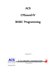
Compact FLASH III Digital Audio System
Table of Contents
Overview ....................................................................................................................................4
Features .................................................................................................................................................... 4
Connections ............................................................................................................................................. 5
Main Connector ................................................................................................................................ 5
Power Supply Connection ......................................................................................................... 5
Built-in Contacts Connection .................................................................................................... 5
Speaker Connection ................................................................................................................... 6
Serial Connector ............................................................................................................................... 6
Remote Volume Connector ............................................................................................................... 7
LINE OUT Connector ....................................................................................................................... 7
LINE IN Connector ........................................................................................................................... 7
PHONES Connector ......................................................................................................................... 7
Quick Start .................................................................................................................................8
Troubleshooting ......................................................................................................................11
No sound, no Green or Red LED(s) flashing ......................................................................................... 11
No sound, Red LED flashing ................................................................................................................. 11
Low sound volume ................................................................................................................................. 11
Programming the Compact FLASH Card ...............................................................................12
Compact Flash Card Requirements ........................................................................................................ 12
Installing and Removing the Compact FLASH Card.............................................................................. 12
Audio Rates Supported .......................................................................................................................... 12
Image Formats Supported....................................................................................................................... 13
Formatting the CF Card ......................................................................................................................... 13
Modes of Operation.................................................................................................................13
CFSound Mode...................................................................................................................................... 14
Filename Formats............................................................................................................................ 14
Sample Filenames .................................................................................................................... 16
File Naming Format for CFSound style operation ................................................................. 17
Compact FLASH Card Loading and Scanning....................................................................... 17
Background Audio Tracks ....................................................................................................... 18
CFSOUND.INI File ................................................................................................................. 19
Quiz / Kiosk Mode ................................................................................................................... 23
Sequential Sound Play-out ...................................................................................................... 25
RS-232 Serial Port Protocol .................................................................................................... 26
DMX Operation .............................................................................................................................. 27
DMX Controller (Master) ....................................................................................................... 27
DMX Device (Slave) ................................................................................................................ 28
Basic Mode ............................................................................................................................................ 30
Diagnostic LED Codes (Red & Green LEDs)..........................................................................31
Green LED ............................................................................................................................................. 31
Red LED Error Flashes .......................................................................................................................... 31
Power Requirements ..............................................................................................................32
Copyright©1992-2011 by ACS, Sarasota, Florida
2
ALL RIGHTS RESERVED
Compact FLASH III Digital Audio System
Digital Audio Recording ..........................................................................................................32
Recommended Recording Procedure ..................................................................................................... 32
Self-Recording Procedure ...................................................................................................................... 32
Optional Plug-in Modules .......................................................................................................34
CFSound-III Contact Sense 8 Module ................................................................................................... 34
CFSound-III Contact I/O 8 Module ....................................................................................................... 34
CFSound-III Contact Sense 24 Module ................................................................................................. 36
CFSound-III DMX I/O Module ............................................................................................................. 37
CFSound-III Video Graphics Adaptor Module ...................................................................................... 38
Contact Wiring....................................................................................................................................... 39
Analog Input Wiring .............................................................................................................................. 40
DMX Wiring.......................................................................................................................................... 40
Connecting a Motion Sensor ..................................................................................................42
Normal Sized Motion Sensor ................................................................................................................. 42
Small Sized Motion Sensor ................................................................................................................... 43
Connecting Multiple Speakers ...............................................................................................44
Controlling Eight LEDs with a Sound Sequence...................................................................45
Light LED while Sound is Playing ..........................................................................................46
Frequently Asked Questions ..................................................................................................47
Sample Messages ...................................................................................................................52
Sample Power Up Message, no CF card ................................................................................................ 52
Sample Power Up Message, CFSound Mode ........................................................................................ 52
Sample Power Up Message, Basic Mode ............................................................................................... 52
Mechanical ..............................................................................................................................53
Firmware Revisions ................................................................................................................54
Upgrading the Firmware .........................................................................................................56
NOTICE: ...................................................................................................................................60
Copyright©1992-2011 by ACS, Sarasota, Florida
3
ALL RIGHTS RESERVED
Compact FLASH III Digital Audio System
Overview
Thank you for purchasing the Compact FLASH III Digital Audio System; be assured that it will
provide you with thousands of hours of trouble free, solid-state operation. You will also find that it is simple
to change audio themes or tracks and is easy to make your own recordings or “program” the device.
End users can change the audio themes or tracks simply by inserting another, different Compact FLASH
Card, as easily as the changing of a cassette tape. Multiple cards can be programmed with different audio
themes or tracks allowing daily, hourly, weekly or monthly changes. It truly is as simple as removing the old
card and plugging in the new one. Depending on the manufacturer, Compact FLASH Cards may be re-used
up to 100,000 times.
Sound files are easily copied onto the card via your PC or laptop, using a Compact FLASH to PCMCIA,
Compact FLASH to USB or parallel port adapter. As the files are copied to the Compact FLASH Card, they
are renamed. This process instructs the Compact FLASH III Digital Audio System how and when to play
the copied files.
See the Quick Start section below to try out your CFSound-III immediately.
Features
The Compact FLASH III Digital Audio System incorporates the following features:
Uses inexpensive, industry standard Compact FLASH (CF) Cards.
Runs on 12 – 15VDC with supplied 120 – 240VAC 50/60Hz wall transformer
RS-232 Serial Port for controlling audio play out via an attached computer or PLC.
Diagnostic LED’s to indicate operating status.
Two built-in contact inputs to activate sounds.
Push-To-Talk (PTT) dry relay contact output that can optionally close whenever a sound is played.
Digital Up/Down volume control push buttons with remote connector.
Built-in 50 Watt Class D Stereo (2 x 25W) Amplifier.
Built-in 35mW @ 32 ohms Headphone Amplifier.
Optional boards for contact inputs to activate sounds.
Optional boards for contact outputs activated with sounds for other control.
Optional board for control of or by USITT DMX-512 devices.
Optional board for display of images and computer graphics with PS/2 input.
Scriptable via built-in ACS Basic
Copyright©1992-2011 by ACS, Sarasota, Florida
4
ALL RIGHTS RESERVED
Compact FLASH III Digital Audio System
Connections
Front View
CFSound-III
DOWN
CF Card Slot
Diagnostic LEDs
UP
Optional Modules
Up / Down
Volume Buttons
RESET
Button
Rear View
MAIN
LINE IN LINE OUT PHONES
AUDIO
3.5mm JACKS
Serial RS-232
DB-9P
SPEAKERS
OUT
Contacts
25 & 26
PTT Relay
Contacts
Power
Main Connector
Most of the connections to the CFSound-III are supplied to the unit with a ten pin, 2-piece pluggable
terminal block style connector at Main.
Power Supply Connection
The CFSound-III requires a regulated or unregulated voltage of 10V to 18V DC. Voltages above 18VDC
will damage the unit. The unit has reset-able fusing internally to protect the Power input. Should the fuse
trip, remove power, correct the fault, wait a minute for the thermal fuse to cool and reset, then, re-apply
power. The non-OEM version of the CFSound-III is supplied with a 120-240VAC 50/60Hz wall mounted
transformer rated at 15VDC @ 1.6A.
ACS supplies different versions of the wall-mounted transformer power supply for the CFSound-III. The
designated positive lead which should be connected to pin 9 of the Main connector with the other negative or
ground lead connected to pin 10.
Built-in Contacts Connection
The Push-To-Talk (PTT) relay dry contact output on the Main connector may be activated whenever a
sound is playing. The contact output is implemented with a relay whose contacts are rated at 1A @ 30VDC
maximum. The Common and Normally Open relay contacts are available on the Main connector.
The contact inputs on the Main connector appear logically to the CFSound-III as Contact #25 & #26,
and may be activated by momentarily applying ground to the Input Contact #xx pin on the Main connector.
The contact inputs are implemented with an optocoupler. The Cathodes of the LEDs in the optocoupler are
connected to the Contact #25 and #26 Input pins. The Anodes of the LEDs in the optocoupler are connected
to an internal 12VDC power supply, with a 680 ohm current limiting resistor in series. The output transistor
of the optocouplers have 10K pull-up resistors on their collectors, with the emitters connected to ground and
Copyright©1992-2011 by ACS, Sarasota, Florida
5
ALL RIGHTS RESERVED
Compact FLASH III Digital Audio System
are buffered by an inverting gate. The following diagram is representative of the Contact #25 input and is
similar for Contact #26:
+5v
+12v
10K
ohm
680
ohm
Contact #25
GROUND
The input is activated by sinking current from the Contact input pin to ground. A Ground connection is
supplied on pin 10 of the Main connector for this purpose. The input current sink requirement is
approximately 10mA. The contacts are associated with sound files named 19x.WAV and 1Ax.WAV. The x
denotes additional file control attribute characters. See the Filename Formats section below.
Speaker Connection
The speaker terminals on the Main connector provide connections for the two external left and right
speakers. These may be either 4 or 8 ohm speakers, with 4 ohms providing higher output power. The speakers
should be capable of handling up to 25 watts.
NOTE: THE SPEAKER OUTPUTS ARE NOT REFERENCED TO GROUND – EACH
SPEAKER REQUIRES ITS OWN PAIR OF WIRES, AND NEITHER WIRE MAY BE
CONNECTED TO GROUND.
Left Speaker +
Left Speaker -
Right Speaker +
Right Speaker -
Input Contact 25
Input Contact 26
PTT Contact COM
PTT Contact N.O.
10V - 18V DC
GROUND
Pin #
1
2
3
4
5
6
7
8
9
10
1
2
3
4
5
6
7
8
9
10
Signal
Left Speaker +
Left Speaker Right Speaker +
Right Speaker Input Contact 25
Input Contact 26
PTT Contact COM
PTT Contact N.O.
10VDC – 18VDC
Ground
Filename
19C.WAV / 19O.WAV
1AC.WAV / 1AO.WAV
Serial Connector
A standard RS-232 serial interface is provided on-board via a DB-9 style male connector. The CFSoundIII provides diagnostic messages about CF card insertion and removal events and sound contents over the
serial port. Additionally, the playing of sounds may be controlled by messages issued to the CFSound-III via
the serial port. The format of the serial data is 2400 baud, 8 data bits, 1 stop bit and no flow control, and the
baud rate may be changed using a configuration file entry or NVM setting. Only three of the nine pins are
Copyright©1992-2011 by ACS, Sarasota, Florida
6
ALL RIGHTS RESERVED
Compact FLASH III Digital Audio System
used. The configuration of jumper block JB2 on the CFSound-III controls whether the serial port looks like a
Modem (DCE) or a Terminal (DTE). As shipped, the CFSound-III is configured to be DCE so that a one-toone cable from a PC serial port may be used. The Windows HyperTerminal accessory may be used to view the
diagnostic messages and manually issue commands to start/stop/queue sounds:
Pin #
2
3
5
Signal Name
JB2 = DCE
TX (from unit)
RX (to unit)
Ground(GND)
Signal Name
JB2 = DTE
RX (to unit)
TX (from unit)
Ground(GND)
Remote Volume Connector
The sound volume level is controlled by two pushbuttons on the front of the CFSound-III: one for Up and
one for Down. A momentary button press of the Up button raises the volume level, a button press of the Down
button lowers the volume level. Pressing and holding the button for ¼ second starts an automatic volume
increase/decrease until the button is released or the maximum/minimum volume is achieved. The volume is
essentially db linear in sixty-four, 1db increments from 0db → -66db.The current volume level is
‘remembered’ in non-volatile memory on the CFSound-III and is restored to it’s last setting upon power-up.
The Up and Down button inputs are also available on the VOL connector along the front edge of the
printed circuit board inside the enclosure. Connecting a momentary button between the input and ground
parallels the operation of the on-board volume controls:
Pin #
1
2
3
Signal
DOWNGND
UP-
LINE OUT Connector
The volume controlled sound is also available at an audio line level (1V RMS @ 0db volume, 47K ohms)
at the 3.5mm Stereo LINE OUT jack on the rear of the CFSound-III.
Pin #
TIP
RING
SLEEVE
Signal
Left
Right
Ground
LINE IN Connector
Line level audio appearing at the 3.5mm Stereo LINE IN jack (1V RMS @ 0db volume, 47K ohms) on
the rear of the CFSound-III may be enabled to be amplified at the current volume setting and presented to the
Speakers/Line Outputs whenever another sound is not playing. See the CFSOUND.INI section below.
PHONES Connector
The volume controlled sound is also available for driving stereo headphones (35mW @ 0db volume, 32
ohms) at the 3.5mm Stereo PHONES jack on the rear of the CFSound-III.
NOTE: The common headphone output is not referenced to, and should not be
connected to Ground.
Pin #
TIP
RING
SLEEVE
Copyright©1992-2011 by ACS, Sarasota, Florida
Signal
Left
Right
Common
7
ALL RIGHTS RESERVED
Compact FLASH III Digital Audio System
Quick Start
Also refer to the videos on the SUPPORT page of the CFSOUND.COM website.
1.
Connect the transformer, speakers and a normally open momentary pushbutton switch to the Main
terminal block. See Main Connector section above for more information.
2.
Apply power to the CFSound-III. With no CF card inserted, the Green LED should flash fast then
slow. See Diagnostic LED Codes section below for more information.
3.
Format a Compact Flash card using either FAT16 (FAT) or FAT32:
Copyright©1992-2011 by ACS, Sarasota, Florida
8
ALL RIGHTS RESERVED
Compact FLASH III Digital Audio System
Copyright©1992-2011 by ACS, Sarasota, Florida
9
ALL RIGHTS RESERVED
Compact FLASH III Digital Audio System
4.
Download the sample sounds from the CFSound website:
http://www.acscontrol.com/Downloads/Products/CF/CFSoundIII/CFSound3TestSounds.zip
5.
Extract the test sounds onto the formatted Compact Flash card. Browse to the CF drive:
6.
Carefully insert the CF card into the CFSound-III. The Green LED should flash fast then go on
steady and the background sounds should start playing then repeating.
7.
Press the button. The CFSound-III should interrupt the background sound, play sound #25, then
resume playing the background sound.
Copyright©1992-2011 by ACS, Sarasota, Florida
10
ALL RIGHTS RESERVED
Compact FLASH III Digital Audio System
Troubleshooting
No sound, no Green or Red LED(s) flashing
The CFSound-III doesn’t have correct power. Verify the power supplied to the MAIN connector for the
correct polarity and level using a voltmeter if available. If this is correct, verify that none of the wiring to the
unit is shorted causing the internal resettable fuse to be tripped. Try removing power, waiting for 15 seconds
and reapplying power to allow the internal fuse to reset.
No sound, Red LED flashing
The Red LED is flashing a pattern of one or more numbers to help identify the problem. Please see the
Diagnostic LED Codes and Frequently Asked Questions sections below. Also refer to the videos on the
SUPPORT page of the CFSOUND.COM website.
Low sound volume
Sound volume may be adjusted using the up / down pushbuttons on the front of the unit. Push and hold
the up button to increase. If this doesn’t adjust the volume, verify your speaker wiring and impedance.
Copyright©1992-2011 by ACS, Sarasota, Florida
11
ALL RIGHTS RESERVED
Compact FLASH III Digital Audio System
Programming the Compact FLASH Card
Compact Flash Card Requirements
The Compact FLASH III Digital Audio System was designed to use only Compact FLASH Cards (CF
Cards) that support the Common Memory ATA mode at 3.3 volt operation. Tested cards include SanDisk,
Techworks, Dane-Elec, Memorex and Hitachi. The SanDisk card was tested, since they manufacture 90% of
the retail cards on the market. Compact FLASH Cards are available in many local electronics or camera stores
or can be ordered directly from ACS.
Note that not all Kingston Media Compact Flash cards are 100% compatible in Common Memory
mode and as such may NOT BE COMPATIBLE with the Compact Flash III Digital Audio System.
The Compact FLASH Card is programmed by inserting it into the PCMCIA slot of a Compact FLASH to
PCMCIA adapter or a Compact FLASH adapter connected to your parallel port. Sound files are copied to the
Compact FLASH Card just as if it were a disk drive. The files used are the standard “*.WAV” files typically
employed by Windows and DOS audio applications for years.
When a new Compact FLASH Card is first installed into your computer, Windows (95 or later) should
recognize the device and install the software necessary to access the card. After the software installation is
complete, the Compact FLASH Card appears as a disk drive icon under My Computer. You may then use
Windows Explorer to drag and drop the sound files from your computer’s hard disk directly to the Compact
FLASH Card icon. It really is just that easy.
Please take care not to use audio tracks that are copyrighted. If you wish to avoid this issue, you will find
that many computer software outlets have CD’s with non-copyrighted music and audio sound effects that you
may use without limitation. They are commonly found in the multimedia section. Please be advised that
you as the user are solely responsible for audio that you record and play from the Compact FLASH
III Digital Audio System.
Installing and Removing the Compact FLASH Card
Care should be taken when installing or removing the Compact FLASH Card. Please be certain to insert
the card with a straight and level motion. Please do not force the card to insert. Otherwise, some of the 50
pins in the socket may become damaged and the card and/or Compact FLASH III Digital Audio System
may become unusable.
Before REMOVING the Compact FLASH Card under Windows 95 or later, Microsoft recommends that
you double click on the PCMCIA icon at the bottom of your computer screen. This will bring up the pc card
[PCMCIA] properties window. Click on socket status tab, and select the card you wish to remove by clicking
on it. Finally, click on the stop button. Windows will then tell you that the card socket services have been
stopped. Under Windows XP you may also right-click on the folder and select Eject. Failure to stop the
card reader and/or eject the CF card may result in incorrect or incomplete data on the card.
On the Compact FLASH III Digital Audio System this will all happen automatically simply by
removing the card.
Audio Rates Supported
The Compact FLASH III Digital Audio System supports 16-bit mono or stereo Windows PCM
format (.WAV) sound files at a sampling rate of 44.1KHz (44,100Hz) only. The Compact FLASH III
Digital Audio System reads the sampling rates and formats encoded in the .WAV sound files whenever a
card is first inserted or a sound play-out is triggered. The unit will not play any file that does not meet these
Copyright©1992-2011 by ACS, Sarasota, Florida
12
ALL RIGHTS RESERVED
Compact FLASH III Digital Audio System
requirements. Further, this error condition should be identified by the red led flashing twice every six
seconds. See the Diagnostic LED Codes section below for more information.
Image Formats Supported
When the optional Video Graphics Adaptor is installed the CFSound also supports associated image files
for display while the sound is being played. Windows .BMP files of monochrome, 4BPP, 8BPP or 24BPP
resolution are supported. Only Joint Photographic Experts Group (JPEG) .JPG files that are sequential and
sRGB encoded for YUV420 color space are supported.
Formatting the CF Card
Compact FLASH cards must only be formatted using the FAT12 (floppy) FAT16 or FAT32 file systems.
NTFS, Linux EXT3 or other file system formats are not supported. The maximum supported partition
size is 4G. The CFSound-III will attempt to locate a valid, active partition on the formatted card in order to be
able to access the files. CF cards that have been previously used in some digital cameras may not be correctly
formatted, or may not have valid partitions defined.
By default, Windows XP will format any Compact Flash card of 64MB or more with FAT32 format. The
ACS Compact FLASH III Digital Audio System uses the FAT (FAT16 or FAT32) format and can not operate
with a NTFS formatted card. You must select FAT or FAT32 file system to format your Compact Flash card
in a Windows XP PC.
Modes of Operation
The CFSound-III can operate in one of two different modes:
1.
Conventional CFSound where the sound play-out is controlled by the association of contact
numbers and sound filenames. This is referred to as the CFSound Mode.
2.
Scriptable CFSound where the sound play-out is controlled by the execution of ACS Basic
programs. This is referred to as the Basic Mode.
Upon power-up, reset or whenever a Compact Flash card is inserted or removed, the unit determines its
operating mode as follows; As the CFSound-III scans for a CF card, and then files on the card, the Green LED
flashes 3 times per second:
If a CF card is not present, the unit runs in Basic Mode by starting the ACS Basic interpreter and
accepting/executing a subset of Basic commands that don’t require file I/O via the serial port and/or a
keyboard attached to the Video Graphics Adaptor PS/2 connector. The Green LED flashes once per second.
If a CF card is present, the unit looks for a file named CFSOUND.BAS and, if found, starts the ACS
Basic interpreter, loading the file and executing the Basic program within in Basic Mode. The Green LED
flashes once per second.
If a CF card is present, and the file CFSOUND.BAS is not found, the unit scans the card looking for
sound files that follow the conventional CFSound Mode Filename Format. If at least one correctly named,
valid sound file is found, the unit runs in CFSound Mode. If no valid sound files named in the conventional
CFSound Mode Filename Format are found, the unit starts the ACS Basic interpreter and accepts/executes
the complete set of Basic commands via the serial port and/or a keyboard attached to the Video Graphics
Adaptor PS/2 connector.
Copyright©1992-2011 by ACS, Sarasota, Florida
13
ALL RIGHTS RESERVED
Compact FLASH III Digital Audio System
CFSound
Starts
No
CF card
detected ?
Yes
CFSOUND.BAS
file found ?
Yes
Start ACS Basic
Load and Run
CFSOUND.BAS
Yes
Run in CFSound
mode
No
CFSound named
files found?
No
Start ACS Basic
with no program
loaded
These two modes of operation are detailed in the following sections. Any errors encountered while
scanning the CF card produce error code flashes on the Red LED. See the Diagnostic LED Codes section
below for more information about LED error codes.
CFSound Mode
In CFSound Mode, the operation of the CFSound-III is controlled by the names of the sound files on the
CF card. Sounds are associated with contacts by the leading numeric portion of the filename, and the
controlling state of the contact is specified by additional trailing non-numeric character attributes. Sounds
may be played when a contact closes, opens, or only while a contact is closed or open. Sounds may be flagged
as non-interruptible, or to only play when no other contact controlled sounds are playing. In addition, a small
configuration text file may be placed onto the CF card along with the sound files to further control how the
unit plays sounds (see the CFSOUND.INI section below).
Filename Formats
The filenames of the individual Sound files on the Compact FLASH Card control how and when the
sounds are played out by the Compact FLASH III Digital Audio System. The filename must follow the
DOS 8.3 naming convention – up to 8 characters of name with up to 3 characters of extension.
Copyright©1992-2011 by ACS, Sarasota, Florida
14
ALL RIGHTS RESERVED
Compact FLASH III Digital Audio System
The filenames must start with the optional input number they are associated with expressed as a
two digit HEX number.
A HEX numeric digit is 0 through 9 and A through F, with 0 being equal to decimal 0, A being equal to
10 and F being equal to 15. The first digit (MSB) of the two digit hex number is multiplied by 16. The
second digit (LSB) is added to the adjusted value derived from the first digit. The number 10 in HEX is thus
equal to 16 decimal. The number 20 in HEX is 32 decimal, 21 in HEX is 33 decimal, and 7F in HEX is 127
decimal. For your convenience, a decimal to hex conversion table is provided below:
LSB
_0
_1
_2
_3
_4
_5
_6
_7
_8
_9
_A
_B
_C
_D
_E
_F
MSB
0_
0
1
2
3
4
5
6
7
8
9
10
11
12
13
14
15
1_
16
17
18
19
20
21
22
23
24
25
26
27
28
29
30
31
2_
32
33
34
35
36
37
38
39
40
41
42
43
44
45
46
47
3_
48
49
50
51
52
53
54
55
56
57
58
59
60
61
62
63
4_
64
65
66
67
68
69
70
71
72
73
74
75
76
77
78
79
5_
80
81
82
83
84
85
86
87
88
89
90
91
92
93
94
95
6_
96
97
98
99
100
101
102
103
104
105
106
107
108
109
110
111
7_
112
113
114
115
116
117
118
119
120
121
122
123
124
125
126
127
8_
128
129
130
131
132
133
134
135
136
137
138
139
140
141
142
143
9_
144
145
146
147
148
149
150
151
152
153
154
155
156
157
158
159
A_
160
161
162
163
164
165
166
167
168
169
170
171
172
173
174
175
B_
176
177
178
179
180
181
182
183
184
185
186
187
188
189
190
191
C_
192
193
194
195
196
197
198
199
200
201
202
203
204
205
206
207
D_
208
209
210
211
212
213
214
215
216
217
218
219
220
221
222
223
E_
224
225
226
227
228
229
230
231
232
233
234
235
236
237
238
239
F_
240
241
242
243
244
245
246
247
248
249
250
251
252
253
254
255
For example, a sound file associated with optional contact input #1 would be named “01.WAV,” a sound
file for input #10 would be named “0A.WAV,” a file for input #16 would be “10.WAV” and a file for input
#36 would be “24.WAV”. There is no input #0 and so “00.WAV” is reserved and should not be used.
There is a maximum of 254 sounds so “FF.WAV” is reserved and should not be used.
The two digit hex input number must be the first two characters in the filename.
Additional letter tokens are appended to the input # in the filename to determine when and how the audio
sound is played. The Compact FLASH III Digital Audio System provides two inputs in its standard
configuration and, by adding optional boards, can be expanded to either 10, 18, 26 or 50 total inputs. The
inputs can be wired to switches or other such devices, either normally opened or normally closed.
Copyright©1992-2011 by ACS, Sarasota, Florida
15
ALL RIGHTS RESERVED
Compact FLASH III Digital Audio System
You can also connect the RS-232 port of the Compact FLASH III Digital Audio System to the RS232 port of your computer or PLC to control up to 254 sounds using serial commands.
The filename letter tokens are described as follows:
If a “C” appears after the hex number in the filename, the sound file will be played on a closure of the
corresponding optional contact input module input or serial command. The sound will start playing when the
associated contact input goes from an open to closed state.
If a “O” appears after the hex number in the filename, the file is played on a opening of the
corresponding optional contact input module input or serial command. The sound will start when the
associated contact input goes from a closed to an open state.
If a “P” after the hex number in the filename, the file will play only while the “C” or “O” state is true. If
“C,” it will play while the associated contact input is closed and it will stop playing the sound when the input
is opened. If “O,” it will play while the associated contact input is open and it will stop playing the sound
when the input is closed.
If an “R” appears in the filename after the hex number, the sound is repeated, that is to say that the same
sound file plays over and over. If used in conjunction with the “P” command, the sound file will repeat the
entire time the “C” or “O” input condition is true. If “C,” the entire time the input is closed, if “O,” the entire
time the input is open. If triggered without a “P” attribute, the file will play indefinitely or until another
sound is played.
If an “S” is used in the filename after the hex number, the on-board Push-To-Talk (PTT) relay and
contact closure corresponding to the input number on an optional plug-in board will be activated when the file
is played.
If a “B” is used in the filename after the hex number, the sound is considered to be a background sound.
Background sounds play when no other sound is playing, and multiple background sounds are played in the
numerical sequence of the two digit input number. Sounds that are marked as Background may not be marked
for contact closure or opening, play while or repeat. Such markings will be ignored.
If an “N” is used in the filename after the hex number, the sound is considered to be a non-interruptible
sound. Sounds that are marked as non-interruptible will play to completion before any other sounds are
played. Contact events that occur while non-interruptible sounds are playing are discarded unless the
SaveNIContacts entry in the optional CFSOUND.INI file [Contacts] section is set to TRUE. Sounds that are
marked as non-interruptible may not be marked for Repeat or as a Background sound. Such markings will be
ignored.
If an “F” is used in the filename after the hex number, the sound is considered to be associated with a
DMX channel Fade. Sounds that are marked for fade will ramp up the associated DMX channel value
between the BeginFadeValue and EndFadeValue entries at the FadeDuration rate in the CFSOUND.INI
file [DMX] section when the sound plays and ramp down when the sound ends or another sound is started.
If a “D” is used in the filename after the hex number, the sound is considered to be associated with one or
more DMX channels defined by an associated scene ##.DMX file.
Sample Filenames
“01C.WAV”
This file would play once, when triggered by optional contact input #1 closing.
“02O.WAV”
This file would play once, when triggered by optional contact input #2 opening.
“04CP.WAV”
“07CPR.WAV”
This file would play once, when triggered by optional contact input #4 closing and play
only while input #4 was closed without repeating.
This file would play and repeat, the entire time optional contact input #7 was closed.
Copyright©1992-2011 by ACS, Sarasota, Florida
16
ALL RIGHTS RESERVED
Compact FLASH III Digital Audio System
“01OPR.WAV”
This file would play and repeat, the entire time optional contact input #1 was open.
“08CNS.WAV”
This file would play once, without being interrupted when triggered by optional contact
input #8 closing. The on-board PTT relay would be activated for the duration of the
sound as well as optional contact output #8.
“7EB.WAV”
This file would play as a background sound whenever any other sound was not playing.
“7FB.WAV”
This file would also play as a background sound after the preceding file 7EB.WAV had
played.
“19C.WAV”
This file would play once, when triggered by contact input #25 on the MAIN connector
on the back of the CFSound-III closing.
“01CD.WAV”
This file would play once, when triggered by optional contact input #1 closing. When
the sound starts, the first 16 DMX channels would be set to values in the 01.DMX
[SoundStart] section, when the sound stops, the first 16 channels would be set to
values in then [SoundStop] section of the same file.
“19CF.WAV”
This file would play once, when triggered by contact input #25 on the MAIN connector
on the back of the CFSound-III closing. When the sound starts, DMX channel #25
would fade-up to values at a rate determined by entries in the CFSOUND.INI file.
When the sound stops DMX channel #25 would fade-down.
“19.BMP”
This image file would display while the sound file 19C.WAV or 19O.WAV is playing.
“01.JPG”
This image file would display while the sound file 01C.WAV or 01O.WAV is playing.
File Naming Format for CFSound style operation
Filename format: XX[COPRSBNFD].WAV
Where:
XX
C
O
P
R
S
B
N
F
D
.WAV
Two digit ASCII Hex identifier 01 - FE, may be associated contact number
File plays on Closure of contact XX, may not be used with O
File plays on Opening of contact XX, may not be used with C
File plays while contact XX is closed or open, may not be used with B
File repeats, may not be used with B
On board PTT relay and contact XX will activate while sound is playing
File plays as background when no other sound is playing, may not be used with C, O, P, R or N
File playing is non-interruptable, may not be used with R or B
Matching DMX channel number Fades up/down with sound start/stop
First 32 channels set to entries in associated DMX scene file with sound start/stop
File extension identifies Windows PCM sound file format
Compact FLASH Card Loading and Scanning
Once programmed with the desired sounds and correct filenames, the card is inserted into the slot on the
front of the Compact FLASH III Digital Audio System. The green LED indicator should begin to flash
indicating that the unit is scanning and loading the files from the card. When the card is correctly loaded and
scanned, the green LED should glow steadily. Any problems encountered while reading the CF card are
indicated by a repeating sequence of flashes on the red LED indicator (see the Diagnostic LED Codes
section below for more information).
The card may be removed at any time. In that case, both the green and red LED indicators should turn
off.
The optional contact inputs are ‘debounced’ by sampling them using a periodic interrupt. The sample
rate is 50 Hertz (20 milliseconds). Valid input closures are detected by reading a 0 - 0 - 1 (open, open,
closed) sample sequence. Valid input opens are detected by reading a 1 - 1 - 0 (closed, closed, open) sample
sequence.
Copyright©1992-2011 by ACS, Sarasota, Florida
17
ALL RIGHTS RESERVED
Compact FLASH III Digital Audio System
The status of the unit while loading and scanning is also displayed via messages sent out the serial port.
Using a PC with “HyperTerminal” or other terminal emulator software connected to the Compact FLASH III
Digital Audio System serial port the card loading and scanning messages may be viewed. The serial data
format is 2400 baud, 8 data bits, 1 stop bit and no flow control. Samples of these messages are shown in the
Appendix.
Background Audio Tracks
Sounds labeled with the “B” token in their filename after the hex number are played in numerical
sequence as background sounds when no other audio tracks are being played, continuously repeating the
sequence. A background audio track will cease playing when any other sound file is triggered to play by
contact closure or serial command. Once that sound file is finished playing, the background audio file that
was playing will resume playing from the point where it was interrupted and continue to play until again
interrupted.
Copyright©1992-2011 by ACS, Sarasota, Florida
18
ALL RIGHTS RESERVED
Compact FLASH III Digital Audio System
CFSOUND.INI File
Support is provided to control various operating parameters by the inclusion of a CFSOUND.INI file on
the CF card. This file is a text file that is created using Notepad or other text editor and then is placed onto
the CF card along with the sound files.
When a card is inserted and after all sound files have been loaded, the CFSound-III unit looks for a file
with this name, and reads initialization parameter entries from it. Parameter entries are organized into
sections with a section name in brackets followed by one or more PARAMETER=VALUE lines. The Section
Names and Parameter entries are case sensitive. A section or parameter may be commented out by placing a
‘#’ character as the first character on the line. The last line in the file should be a blank line.
NOTE: THE CFSOUND.INI FILE IS NOT REQUIRED IF YOU ARE NOT ALTERING A
PARAMETER FROM THE DEFAULT VALUE SHOWN IN THE TABLE.
SECTIONS AND PARAMETERS THAT ARE NOT BEING CHANGED FROM THEIR
DEFAULT VALUES IN THE TABLE ARE ALSO NOT REQUIRED IN THE FILE.
INCLUDING A [DMX] OR [Video] SECTION AND PARAMETERS WHEN THE REQUIRED
MODULE IS NOT INSTALLED WILL GENERATE AN ERROR INDICATION.
Here is a list of currently supported Sections and Parameter entries:
[Section] / Parameter
[Comm]
BaudRate=ddddd
[DEBUG]
ShowStartStop=TRUE/FALSE
[Background]
BackgroundDelay=ddddd
BackgroundRestart=TRUE/FALSE
[Quiz]
QuizMode=TRUE/FALSE
QuestionContacts=dd
AnswerContacts=dd
NoAnswerTimeout=dd
AwaitAnswerSound=xx
Copyright©1992-2011 by ACS, Sarasota, Florida
Description
Communications Port Section
Sets the serial port baudrate to the
decimal value ddddd.
Default=2400.
Debug Section
Enables RS-232 message display of sound
start/stop events.
Default=FALSE.
Background Section
Sets the delay in seconds between
background sound play-outs to the decimal
value ddddd. The delay starts when a
background sound is started in order to
maintain the delay interval regardless of
the sound(s) length.
Default=0.
Enables interrupted background sound to
restart from the beginning instead of where
it was interrupted.
Default=FALSE.
Quiz Section
Enables Quiz/Kiosk mode of operation.
Default=FALSE.
Sets the number of question contacts to the
decimal value dd.
Default=4.
Sets the number of answer contacts to the
decimal value dd.
Default=4.
Sets the delay in seconds between the end
of the question sound and the timeout
answer sound to the decimal value dd.
Default=5.
Sets the hexadecimal sound number xx to
19
ALL RIGHTS RESERVED
Compact FLASH III Digital Audio System
[Section] / Parameter
QuestionTimeout=dd
AnswerWithoutQuestionSound=xx
[Contacts]
Force=TRUE/FALSE
SequenceContactNumber=dd
FirstSoundNumber=dd
LastSoundNumber=dd
SaveNIContacts=TRUE/FALSE
OutputContactModulus=dd
RandomSequence=TRUE/FALSE
OffsetContactNumber=dd
Copyright©1992-2011 by ACS, Sarasota, Florida
Description
play after the question sound before the
timeout answer sound.
Default=0 (no sound).
Sets the delay in seconds between the end
of the quiz question while waiting for a
answer.
Default=30.
Sets the hexadecimal sound number xx to
play if an answer contact is activated
before a question contact.
Default=0 (no sound).
Contacts Section
Setting this value to TRUE restores the
original CFSound contact behavior wherein
the contact's active status is 'forced'
upon reset, power-up or card-insertion.
This will cause associated sound activation
if the contact was active.
Setting this value to FALSE (the default)
causes the new behavior wherein the
contact's current status is sampled upon
reset, power-up or card-insertion. This
will cause no associated sound activation
until the contact is re-activated.
Default=FALSE.
Sets the number of the contact that will
play sounds in sequence to the decimal
value dd.
Default=0 (no sequencing)
Sets the first sound number that will be
played in sequence to the decimal value dd.
Default=1 (sound #1)
Sets the last sound number that will be
played in sequence to the decimal value dd.
Default=127 (sound #127)
Setting this value to TRUE will remember
any contact events that occur while a noninterruptible sound is playing. Note that
this can cause a non-interruptible sound to
play again if its contact is re-activated
while it is playing.
Default=FALSE
Setting this value to non-zero will cause
the output contacts associated with sounds
to repeat on the modulo value if
QuizMode=FALSE.
Example: OutputContactModulus=4 activates
contact outputs 1 through 4 for sounds 1
through 4, contact outputs 1 through 4 for
sounds 5 through 8, etc.
Default=0
Setting this value to TRUE will cause each
activation of the SequenceContactNumber to
play a random sound from the range
FirstSoundNumber to LastSoundNumber.
Default=FALSE
Sets the number of the contact that will
offset the sounds associated with the other
contacts by ContactOffsetAmount to the
20
ALL RIGHTS RESERVED
Compact FLASH III Digital Audio System
[Section] / Parameter
ContactOffsetAmount=dd
AutoplayEntireSequence=TRUE/FALSE
LineInputEnableContactNumber=dd
PttOutputWithLineInputContact
=TRUE/FALSE
[LineIn]
LineInputAlwaysEnabled=TRUE/FALSE
[DMX]
IsMaster=TRUE/FALSE
SlaveBaseChannel=ddd
FrameDelay=dd
NumberOfChannels=ddd
BeginFadeValue=ddd
EndFadeValue=ddd
Copyright©1992-2011 by ACS, Sarasota, Florida
Description
decimal value dd. Does not affect Sequence
or Quiz mode.
Default=0 (no offset)
Sets the value that will be added the the
input contact number when the
OffsetContactNumber input is active, to
offset the actual sound number that will
play to the decimal value dd. Does not
affect Sequence or Quiz mode.
Default=0 (no offset amount)
Setting AutoplayEntireSequence to TRUE
causes the entire sequence of sounds to be
played once whenever the
SequenceContactNumber activates one time.
Default=FALSE (no autoplay)
Sets the number of the contact that will
stop any sound currently playing and enable
the Line level Input to the decimal value
dd. Audio on the Line level Input is
amplified to the current volume setting and
appears on the speaker and Line level
Output.
Default=0 (no Line In control contact)
Setting this value to TRUE will cause the
PTT relay to follow the non-zero
LineInputEnableContactNumber state,
otherwise the PTT relay activation is
controlled by sounds with the Relay
attribute in their filename.
Default=FALSE (PTT for sounds w/Relay attr)
LineIn Section
Setting this value to TRUE enables the Line
level Input always when no sound is
playing. When this is FALSE, the Line level
Input is controlled by the
LineInputEnableContactNumber.
Default=FALSE (Line level Input disabled)
DMX Section
Setting this value to TRUE enables the
CFSound as a DMX controller. When this is
FALSE, the CFSound is a DMX device.
Default=FALSE (DMX device)
Sets the base channel number for the group
of channels that the CFSound monitors when
configured as a DMX device
(IsMaster=FALSE).
Default=1
Sets the delay times 20mSEC between
transmitted DMX frames.
Default=0 (no delay)
Sets the number of transmitted channels per
DMX frame, always a multiple of 2.
Default=512
Sets the DMX channel value for the start of
the Fade Up when the associated sound
plays, and the value for the end of the
Fade Down when the sound ends.
Default=0
Sets the DMX channel value for the end of
21
ALL RIGHTS RESERVED
Compact FLASH III Digital Audio System
[Section] / Parameter
FadeDuration=dd
[Video]
DisplayMode=d
Description
the Fade Up when the associated sound
plays, and the value for the start of the
Fade Down when the associated sound ends.
Default=255
Sets the length of the DMX channel Fade Up
/ Fade Down when the associated sound
plays, 0 = full on/off.
Default=1
Video Section
Sets the Video Graphics Adaptor display
mode.
Default=0
Sample CFSOUND.INI files
These three lines typed into a text file with a text editor and saved on the CF card as CFSOUND.INI
along with sounds named with the Background filename attribute provides a 5 minute (300 second) delay
between played background sounds:
[Background]
BackgroundDelay=300
These six lines typed into a text file with a text editor and saved on the CF card as CFSOUND.INI along
with sounds named 01C.WAV, 02C.WAV, … , 08C.WAV will play in a sequence with the next sound in the
sequence played whenever that contact #25 input is momentarily closed.
[Contacts]
SequenceContactNumber=25
FirstSoundNumber=1
LastSoundNumber=8
AutoplayEntireSequence=FALSE
The CFSound-III only supports a single sequence using this approach – for multiple sequences with
different contact inputs an ACS Basic program must be written – see the ACS Basic User’s Manual for an
example.
Copyright©1992-2011 by ACS, Sarasota, Florida
22
ALL RIGHTS RESERVED
Compact FLASH III Digital Audio System
Quiz / Kiosk Mode
The CFSound-III may be configured to operate in a Quiz or Kiosk mode. This mode is enabled by
including the requisite [Quiz] section entries in a CFSOUND.INI file on the card with the
QuizMode=TRUE parameter.
In Quiz mode, Question contacts trigger the Question sounds, then Answer contacts trigger the Answer
sounds related to the question that was activated. The Question contacts start at contact 1 and are contiguous
through the number of QuestionContacts=dd parameter. The Question sounds would be named 01C.WAV,
02C.WAV, … , xxC.WAV where xx is the hexadecimal equivalent of the QuestionContacts=dd parameter.
The Answer contacts immediately follow the Question contacts and are contiguous through the number of
AnswerContacts=dd parameter. Each Answer contact is associated with an array of Answer sounds, with the
offset into the array controlled by the Question contact that was activated. There is also an additional timeout
Answer sound that will be played if an Answer contact is not activated within the NoAnswerTimeout=dd
seconds interval.
Due to the maximum number of sounds being limited to 255 the following limitation must
be observed:
QuestionContacts x (AnswerContacts + 1) <= 254
The next table shows a sample of Quiz mode sound file names and their contact associations given the
following values for the [Quiz] section parameters: QuestionContacts=4, AnswerContacts=4,
AnswerWithoutQuestionSound=7E and AwaitAnswerSound=7F in the CFSOUND.INI file. Notice how
the Answer contacts play different sounds depending upon what Question contact was activated:
Sound Filename
01CS.WAV
02CS.WAV
03CS.WAV
04CS.WAV
05CS.WAV
06CS.WAV
07CS.WAV
08CS.WAV
09.WAV
0ACS.WAV
0BCS.WAV
0CCS.WAV
0DCS.WAV
0E.WAV
0FCS.WAV
10CS.WAV
11CS.WAV
12CS.WAV
13.WAV
14CS.WAV
15CS.WAV
16CS.WAV
17CS.WAV
18.WAV
7EC.WAV
7F.WAV
Contact #
1
2
3
4
5
6
7
8
5
6
7
8
5
6
7
8
5
6
7
8
5,6,7,8
-
Copyright©1992-2011 by ACS, Sarasota, Florida
Description
Question #1 sound
Question #2 sound
Question #3 sound
Question #4 sound
Question #1 Answer #1 sound
Question #1 Answer #2 sound
Question #1 Answer #3 sound
Question #1 Answer #4 sound
Question #1 no Answer Timeout
Question #2 Answer #1 sound
Question #2 Answer #2 sound
Question #2 Answer #3 sound
Question #2 Answer #4 sound
Question #2 no Answer Timeout
Question #3 Answer #1 sound
Question #3 Answer #2 sound
Question #3 Answer #3 sound
Question #3 Answer #4 sound
Question #3 no Answer Timeout
Question #4 Answer #1 sound
Question #4 Answer #2 sound
Question #4 Answer #3 sound
Question #4 Answer #4 sound
Question #4 no Answer Timeout
Answer Without Question Sound
Awaiting Answer Sound
23
sound
sound
sound
sound
ALL RIGHTS RESERVED
Compact FLASH III Digital Audio System
Note that while these sample files all have the ‘C’ contact closure token in the filename, the ‘O’ contact
open token may be used as well. Sound files that are played without a direct contact closure do not require
these tokens.
There are two additional, optional sounds that may be played in Quiz mode. The
AwaitAnswerSound=xx parameter, if xx is non-zero, causes sound file xx.WAV to be played after the
question sound while awaiting an Answer contact activation. In the preceding example, this would play sound
file 7F.WAV. The duration of this optional sound or the NoAnswerTimeout=dd seconds parameter,
whichever is greater, determines the interval before the associated no answer timeout sound file is played. The
AwaitAnswerSound should not be marked as non-interruptible.
The AnswerWithoutQuestionSound=xx parameter if xx is non-zero causes sound file xx.WAV to be
played if an Answer contact is activated before a Question contact to prompt user to select question first. In
the preceding example, this would play sound file 7EC.WAV when any Answer contact is activated before a
Question contact.
A Kiosk mode of operation may be obtained by setting the NoAnswerTimeout=dd parameter to zero.
This effectively disables the AwaitAnswerSound and all of the No Answer Timeout sounds simply
allowing the Question contact to select different sets of Answer contacts sounds such as various languages or
features. After a Question contact is activated, it remains active selecting a given set of Answer contact sounds
until another Question contact is activated.
Contact outputs may also be activated for Question and Answer sounds by using the ‘S’ token in the
filename. In Quiz mode, Question contact outputs remain active for the duration of the Question/Answer
cycle. In Kiosk mode, the last Question (answer selection) contact output remains active until another
Question input is activated. Note that the Answer contact outputs associated with the Answer contact inputs
are used for each set of answers, independent of which Question contact is activated. Unique Answer contact
outputs may be achieved by constructing a matrix using the Question contact outputs as Rows and the
repeating Answer contact outputs as Columns (or vice versa). This is shown in the following diagram:
+V
QUESTION 1
Q1
QUESTION 2
Q2
QUESTION 3
Q3
QUESTION 4
Q4
A1
Q1
A1
Q2
A1
Q3
A1
Q4
+V
Ax
Qx
ANSWER 1
A2
Q1
A2
Q2
A2
Q3
A2
Q4
A3
Q1
A3
Q2
A3
Q3
A3
Q4
A4
Q1
A4
Q2
A4
Q3
A4
Q4
= INDICATOR
= CONTACT OUTPUT
ANSWER 2
ANSWER 3
ANSWER 4
Matrix Wiring of Question/Answer Contact Outputs
Copyright©1992-2011 by ACS, Sarasota, Florida
24
ALL RIGHTS RESERVED
Compact FLASH III Digital Audio System
The BackgroundDelay=ddddd parameter can be used in conjunction with one or more background
sounds to provide a delay between sounds, so that they can be used as an attention getting attract mode.
Sequential Sound Play-out
The CFSound-III may be configured to allow a single contact closure (or opening) to play several sounds
in sequence; one each time it is closed (or opened). This mode is enabled by including the requisite
[Contacts] section entries in a CFSOUND.INI file on the card with the SequenceContactNumber=dd
parameter set to a non-zero, valid contact number from 1 to 8 (1 to 24 with Contact Sense 24 module) or 25
and 26 (rear of unit contact inputs). A single sequence triggered from a single contact input is supported –
for multiple sequences the unit can be scripted in ACS Basic.
The range of sounds that may be played in sequence may be constrained by the addition of two other
parameter entries in the [Contacts] section. The FirstSoundNumber=dd parameter controls the starting
sound number of the sequence, and the LastSoundNumber=dd parameter controls the ending sound number
in the sequence. Setting the FirstSoundNumber parameter to a higher number than the LastSoundNumber
will cause the sounds to be played in reverse sequence, higher number to lower number. The sequence wraps
around to the beginning or end.
For example to play normal sounds on the first 8 contacts, and sequence through 16 different sounds for
the 25th contact, a card would be prepared with the 24 sound files named 01C.WAV – 18C.WAV. Then a
CFSOUND.INI file would be added to the card with the entries:
[Contacts]
SequenceContactNumber=25
FirstSoundNumber=9
LastSoundNumber=24
The first eight contacts would each play their associated sound. Each closure of contact 25 would play a
sound from 09C.WAV – 18C.WAV then repeat from 09C.WAV – 18C.WAV in sequence. To reverse the
order of the sound play-out set the FirstSoundNumber=24 and the LastSoundNumber=9.
To cause the entire sequence of sounds to be played once whenever the SequenceContactNumber is
activated, set the AutoplayEntireSequence parameter to TRUE. For example a museum exhibit needs to play
a sequence of 8 sounds when triggered with each sound activating a relay output while it is playing. A CF
card would be prepared with the 8 sound files in the sequence named 01CNS.WAV – 08CNS.WAV. Then a
CFSOUND.INI file would be added to the card with the entries:
[Contacts]
SequenceContactNumber=25
FirstSoundNumber=1
LastSoundNumber=8
AutoplayEntireSequence=TRUE
Whenever contact 25 is closed, the eight sounds 01CNS.WAV – 08CNS.WAV would play in sequence,
each sound activating its output relay. This feature only works for non-random sequences. The addition of the
non-interruptible attribute to the file names prevents multiple contact 1 closures from prematurely advancing
the sequence.
Please see the videos on the SUPPORT page of the CFSOUND.COM website.
Copyright©1992-2011 by ACS, Sarasota, Florida
25
ALL RIGHTS RESERVED
Compact FLASH III Digital Audio System
RS-232 Serial Port Protocol
Sound play-out may also be controlled via commands received via the serial port. The data format is the
current baud rate (default is 2400 baud), 8 data bits, 1 stop bit and no flow control. Sounds may be started,
queued and stopped using a simple ASCII protocol:
<SOH> p {+/-/&/~/!} XX <ETX>
where:
<SOH>
p
{+/-}
{&/~/!}
XX
<ETX>
= ASCII Start of Header character 0116 (Ctrl-A)
= ASCII lower case letter ‘p’
= ASCII plus character ‘+’ to start a sound, minus
character ‘-‘ to stop a sound
= ASCII ampersand character ‘&’ to queue a sound, tilde
character ‘~‘ to flush the queued sounds, exclamation
character ‘!’ to stop the current playing sound and flush
the queued sounds
= ASCII two digit hexadecimal number XX16 of the sound (01,
02, . . . , 7E, 7F, . . . , FE (maximum))
= ASCII End of Text character 0316 (Ctrl-C)
Up to 128 sounds may be queued. Sounds that are queued are played in succession in the order that they
were queued only when no other sound is playing until the queue is exhausted or flushed. Note that this can
occur at the end of the current background sound file before it repeats. A background or other sound that is
playing may be stopped by issuing a “<SOH>p-00<ETX>” serial command sequence to allow queued sounds
to be heard. The background sound will be resumed when the queue has emptied.
Sound volume may also be controlled via commands received via the serial port. The volume is
essentially db linear in sixty-four, 1db increments from -66db (value of 0) → 0db (value of 63). The current
volume level is ‘remembered’ in non-volatile memory on the CFSound-III and is restored to the last setting
upon power-up. Sound volume may be set, increased or decreased using a simple ASCII protocol:
<SOH> v {=/+/-/<} XX <ETX>
where:
<SOH>
v
{=}
{+/-}
{<}
XX
<ETX>
= ASCII Start of Header character 0116 (Ctrl-A)
= ASCII lower case letter ‘v’
= ASCII equals character ‘=’ to set the volume to the
absolute value XX
= ASCII plus character ‘+’ to increase the volume by XX,
minus character ‘-‘ to decrease the volume by XX
= ASCII less than ‘<’ to fade the volume to 0 over XX
seconds
= ASCII two digit hexadecimal value XX16 of the volume
modification (00, 01, . . . , 3E, 3F) = (0 → 63)
= ASCII End of Text character 0316 (Ctrl-C)
The speaker amplifier may also be muted via commands received via the serial port. Muting does not
affect the current volume setting and is automatically turned off whenever the CFSound is Reset. The speaker
amplifier may be muted / un-muted using a simple ASCII protocol:
<SOH> a {+/-} <ETX>
Copyright©1992-2011 by ACS, Sarasota, Florida
26
ALL RIGHTS RESERVED
Compact FLASH III Digital Audio System
where:
<SOH>
a
{+/-}
<ETX>
= ASCII Start of Header character 0116 (Ctrl-A)
= ASCII lower case letter ‘a’
= ASCII plus character ‘+’ to un-mute the speaker amplifier,
minus character ‘-‘ to mute the speaker amplifier
= ASCII End of Text character 0316 (Ctrl-C)
DMX Operation
The CFSound-III can be configured to be a DMX controller (Master) or DMX device (Slave). Upon
power-up, reset or CF card insertion, the CFSound-III looks for the presence of an installed DMX I/O
module. If found, the mode of DMX operation is controlled by the CFSOUND.INI file IsMaster parameter as
well as the presence of the DMX Scene or Fade filename attributes.
DMX Controller (Master)
The CFSound-III becomes a DMX controller (Master) when it finds files on the CF card with the DMX
Scene or Fade filename attributes, OR, when it reads the CFSOUND.INI file and finds a [DMX] section with
the IsMaster parameter set to TRUE (see the Filename Formats and CFSOUND.INI sections above). As a
DMX controller the CFSound produces the serial data stream that commands the daisy-chain connected
DMX devices to brighten/dim, move, pan or otherwise respond to their DMX channel values.
When a sound is played with the filename Fade attribute, the CFSound begins a fade-up of the channel
value with the same number as the sound. When the sound stops playing a fade-down of the channel value
occurs. The beginning and ending channel fade values as well as the fade duration can be controlled by entries
in the CFSOUND.INI file.
When a sound is played with the filename Dmx scene attribute, the CFSound sets the first 16 channels
(increased to 32 channels in firmware v4.15 and later) to values obtained from an associated ##.DMX file –
the ## must match the two character sound number of the associated ##CDx.WAV or ##ODx.WAV file. The
content of the .DMX text files follow a similar format as the CFSOUND.INI file:
[Section] / Parameter
[SoundStart]
1=ddd
2=ddd
...
16=ddd
[SoundStop]
1=ddd
2=ddd
...
16=ddd
Copyright©1992-2011 by ACS, Sarasota, Florida
Description
Sound Start section
Sets the value of channel 1 to ddd (0 to 255) when
this sound starts.
Default=0
Sets the value of channel 2 to ddd (0 to 255) when
this sound starts.
Default=0
...
Sets the value of channel 16 to ddd (0 to 255) when
this sound starts.
Default=0
Sound Stop section
Sets the value of channel 1 to ddd (0 to 255) when
this sound stops.
Default=0
Sets the value of channel 2 to ddd (0 to 255) when
this sound stops.
Default=0
...
Sets the value of channel 16 to ddd (0 to 255) when
this sound stops.
Default=0
27
ALL RIGHTS RESERVED
Compact FLASH III Digital Audio System
DMX Device (Slave)
The CFSound-III becomes a DMX device (Slave) when it finds no files on the CF card with the DMX
Scene or Fade filename attributes, OR, when it reads the CFSOUND.INI file and finds a [DMX] section with
the IsMaster parameter set to FALSE (this is the default, see the Filename Formats and CFSOUND.INI
sections above). As a DMX device the CFSound monitors the serial data stream that commands all daisychain connected DMX device’s channel values.
The CFSound-III monitors a group of three channels, starting at the channel selected by the
SlaveBaseChannel parameter of the CFSOUND.INI file for changes in value. Sounds may be stopped,
started and queued by setting the DMX Sound Number channel value to the desired sound number and
toggling the DMX Command channel value between 0 (no operation) and one of the other command values:
DMX Channel Number
Register
SlaveBaseChannel + 0
Command
SlaveBaseChannel + 1
Sound Number
SlaveBaseChannel + 2
Volume
Description
0 = No operation
1 = Play Sound Number
2 = Stop playing Sound Number
3 = Queue Sound Number
4 = Clear queue
5 = Stop playing and clear queue
6 = Mute amplifier
7 = Un-mute amplifier
0 to 254
When stopping 0 = all sounds
0 to 255
Up to 128 sounds may be queued. Sounds that are queued are played in succession in the order that they
were queued only when no other sound is playing until the queue is exhausted or cleared. Note that this can
occur at the end of the current background sound file before it repeats. A background or other sound that is
playing may be stopped by issuing a ‘stop playing all sounds’ command sequence to allow queued sounds to
be heard. The background sound will be resumed when the queue has emptied.
Sound volume may also be controlled by changing the value of the DMX Volume channel. The 256
channel values are mapped to the 64 volume values by dividing the channel value by 4. The resulting volume
is essentially db linear in sixty-four, 1db increments from -66db (value of 0) → 0db (value of 63). The current
volume setting is not ‘remembered’ by the CFSound between power-up, reset, or CF card insertions. Note that
the volume push buttons on the front of the unit will appear to not work since their ‘settings’ are constantly
being over-ridden by received DMX frames containing a received volume setting.
Here’s an example - CFSOUND.INI file contains:
[DMX]
SlaveBaseChannel=50
Initially DMX channels SlaveBaseChannel+0 through SlaveBaseChannel+2 should be set to zero. This is
the no operation command, with the volume set to minimum:
DMX Channel
50
51
52
Copyright©1992-2011 by ACS, Sarasota, Florida
Value
0
0
0
Description
No Operation Command
Sound Number
Volume
28
ALL RIGHTS RESERVED
Compact FLASH III Digital Audio System
To start a sound playing, set the SlaveBaseChannel+1 to the sound number, set the SlaveBaseChannel+2
to the desired volume, then set the SlaveBaseChannel+0 to 1. To play sound number 10 at full volume:
DMX Channel
50
51
52
Value
0
10
255
Description
No Operation Command
Sound Number
Volume
Then issue the Play Sound command by changing the Command channel’s value from No Operation to
Play Sound– the transition from No Operation to a command value causes the command to take effect:
DMX Channel
50
51
52
Value
1
10
255
Description
Play Sound Command
Sound Number
Volume
After the DMX frame has been sent, the SlaveBaseChannel+0 can be set back to zero – no operation – in
preparation for the next command:
DMX Channel
50
51
52
Value
0
10
255
Description
No Operation Command
Sound Number
Volume
The SlaveBaseChannel+2 continually updates the CFSound-III volume as DMX frames are received –
this channel’s value can be tied to a potentiometer or slider on the DMX master’s console to adjust the
volume.
To stop all sounds that have been queued and are playing:
DMX Channel
50
51
52
Value
5
n/a
255
Description
Stop Playing Clear Queue Command
Sound Number (don’t care)
Volume
After the DMX frame has been sent, the SlaveBaseChannel+0 can be set back to zero – no operation – in
preparation for the next command:
DMX Channel
50
51
52
Copyright©1992-2011 by ACS, Sarasota, Florida
Value
0
n/a
255
Description
No Operation Command
Sound Number (don’t care)
Volume
29
ALL RIGHTS RESERVED
Compact FLASH III Digital Audio System
Basic Mode
In Basic Mode, the operation of the CFSound-III is controlled by the interpreted execution of a user
written program that is written in the ACS Basic language. BASIC is the acronym for Beginners’ Allpurpose Symbolic Instruction Code – an easy to learn programming language developed by Kemeny & Kurtz
at Dartmouth in 1964. Programs consist of numbered lines with one or more English keywords describing the
operations that the user wants to have performed.
The BASIC interpreter built-in to the CFSound-III implements most of the language elements for working
with integers, strings and files as well as providing access to the CFSound-III hardware features such as
contacts, timers, clock and playing sounds. The language elements are outlined in the separate document
“ACS Basic User’s Manual” available for download on the CFSound website.
Programs may be developed three different ways:
1.
Interactively using an installed Video Graphics Adaptor module with an attached display and
PS/2 keyboard. Program statements comprised of language elements are interactively keyed-in,
developing and debugging programs that may be saved on the CF card. This is the optimum
development methodology as the CFSound-III can be programmed and used without a PC.
2.
Interactively using a terminal emulator such as Windows HyperTerminal connected to the
CFSound-III’s serial port. Operation is similar to 1. above only via the host PC’s user interface
and serial port. See the “Upgrading the Firmware” section at the end of this manual for a
description of the required cabling and HyperTerminal settings. This is the preferred
development methodology.
3.
Offline using a text editor such as Windows Notepad. The files are then saved onto the CF card
for debugging when inserted into the CFSound. This methodology is slow, cumbersome and
error-prone since it is not interactive and errors cannot be viewed or addressed in-situ
and is not recommended.
Once a program has been developed and tested, it may then be placed or saved onto the CF card named as
CFSOUND.BAS along with any other required files. The CFSound will then load and execute this file upon
power-up, reset or CF card insertion, effectively customizing the unit’s function.
Copyright©1992-2011 by ACS, Sarasota, Florida
30
ALL RIGHTS RESERVED
Compact FLASH III Digital Audio System
Diagnostic LED Codes (Red & Green LEDs)
Green LED
Flashes three times a second while scanning or loading CF Card files.
Steady on when loaded, ready or playing in CFSound mode.
Flashes once a second while running ACS Basic mode
Toggles three times a second alternating with the Red LED while self-recording.
Red LED Error Flashes
The Red LED can indicate up to 4 error conditions by flashing 1 to 4 unique numeric code patterns from the
following table in a continuously repeating sequence. The Red LED flashes at two and a half times a second
for the value of the pattern, followed by a gap of six tenths of a second, then the next pattern is presented.
When self-recording the Red LED alternates with the Green LED three times a second while the recording is
armed, and is Steady On while recording.
Flash
Count
1
2
3
4
5
6
7
8
9
10
11
12
13
14
15
16
17
18
19
20
21
CFSound
Stops
Error Condition
Problem w/ATA interface, non-compatible CF card, bad CF card, execution stops.
Error opening .WAV file for that input, incorrect filename, file does not exist.
Error when reading file, file corrupted, unsupported file type, the sound doesn’t start
or stops playing.
No valid “*.WAV” files of a CFSound Mode Filename Format found on the CF
Card – starting ACS Basic. This code will continue until a Basic RUN command is
issued.
No valid FAT or FAT32 file system found on the CF Card, execution stops.
Error seeking within file when starting or resuming sound, the sound doesn’t start or
resume.
Error initializing CODEC, execution stops.
Invalid .WAV file internal structure, file is ignored.
Unsupported .WAV format (not Windows PCM), file is ignored.
Unsupported .WAV sample rate (not 44.1KHz), file is ignored.
Unsupported .WAV sample size (not 16-bit), file is ignored.
Contact closure without matching sound file, a contact closure with matching sound
file stops this code from flashing.
Speaker is muted by RS-232 command or ACS Basic command.
Problem with CFSOUND.INI file entries.
CFSOUND.INI [DMX] section with no DMX I/O module detected.
CFSOUND.INI [Video] section with no Video Generator module detected.
Unsupported [Video] DisplayMode specified
Error displaying image file on Video Generator
Error writing file when self-recording
Error closing file when self-recording
Error renaming .TMP file at end of self-recording
Copyright©1992-2011 by ACS, Sarasota, Florida
31
•
•
•
•
•
•
•
•
•
•
•
ALL RIGHTS RESERVED
Compact FLASH III Digital Audio System
Power Requirements
The idle current of a CFSound-III unit, no expansion modules with a 4GB SanDisk CF card installed is
~100mA @ 12VDC input.
With a background sound playing at a moderate level, the current consumption averages ~200mA @
12VDC.
Digital Audio Recording
Initially make all recordings (either music or voice) with a sample rate of at least 44.1KHz and 16-bit
mono or stereo. This high quality, first-generation recording will later provide the greatest bandwidth and
produce the best sounding final audio.
Recommended Recording Procedure
1.
Record any audio clip of your choosing @ 44KHz, 16-bit, Mono or Stereo. Make sure that your samples
do not clip (go above or below the sample window). The peaks of your audio clip, should, however, fill
vertically at least 95% of the sample window. If they do not, you will need to boost your input signal by
using a pre-amp or by some other means.
2.
Edit the clip until satisfied. You can use a sound editor or filter program, such as Syntrillium’s Cool
Edit to normalize the amplitude of the sample. Use this command cautiously though, since it also tends
to amplify noise levels. It is always preferable to re-record your sound clip at a higher level to achieve
better fidelity.
It is imperative that all initial editing and filtering be done to the audio clip while it is formatted at 16- bit
stereo and 44.1KHz. Please be certain that your recording environment is absolutely quiet.
Also remember that digital play-out devices do not introduce any static of their own other than
quantization noise. They only play back exactly what was recorded. If there is excessive static in the audio
clip or sample, then there was probably static in it originally.
Please see the videos on the SUPPORT page of the CFSOUND.COM website for additional information.
Self-Recording Procedure
Starting with firmware version v4.17 the CFSound-III has the ability to self-record audio presented at the
line-level inputs into a contact associated .WAV file on the CF card. This requires a freshly formatted
relatively fast CF card to operate properly – slow or fragmented CF cards may cause glitches in the
recordings.
1.
Connect your audio source to the CFSound line-level inputs. The audio level must be adjusted externally
to avoid low volume and/or clipping in the recording.
2.
Press and hold both CFSound volume up/down buttons. After about half a second the Green and Red
LEDs underneath the CF card should begin toggling back and forth indicating that the recording process
is Armed. Once the LEDs start toggling, the volume buttons may be released. On a freshly formatted CF
card, the buttons would need to be held during Reset/Power Up to prevent Basic from starting since there
are no contact named .WAV files on the card.
Copyright©1992-2011 by ACS, Sarasota, Florida
32
ALL RIGHTS RESERVED
Compact FLASH III Digital Audio System
3.
Now close and hold the contact that the recording is to be associated with. The Red LED should stay on
solid while the Green LED continues to blink - indicating that the CFSound is recording. When the
contact is opened the recording will stop, the Red LED will go out and the file will be renamed to
associate it with the contact closure. Problems during or after the recording are indicated by a flashing
Red LED error code. Pressing the contact again should play back the recorded sound.
4.
Repeat this process for any other sounds you wish to record and associate with contact closures.
Copyright©1992-2011 by ACS, Sarasota, Florida
33
ALL RIGHTS RESERVED
Compact FLASH III Digital Audio System
Optional Plug-in Modules
The Compact FLASH III Digital Audio System supports optional plug-in modules to provide Contact
I/O and audio power amplifier capability. Up to two modules may be installed along the front and back of the
unit.
CFSound-III Contact Sense 8 Module
This module provides eight contact inputs. The contacts on the rear module are numbered 1 through 8 and
are associated with sound files named 01x.WAV through 08x.WAV. The contacts on the front module are
numbered 33 through 40 and are associated with sound files named 21x.WAV through 28x.WAV. The x
denotes additional file control attribute characters. See the Filename Formats section above.
8
7
6
5
4
3
INPUT8
INPUT7
INPUT6
INPUT5
INPUT4
INPUT3
INPUT2
2
1
INPUT1
9
GROUND
10
GROUND
The Input connector INP1 consists of a 10 pin, 2 piece terminal block style connector. See the Contact
Wiring section below for a discussion of the electrical input structure and connections. The pinout is shown
in the following rear diagram and table:
INP1
INP1 Pin #
1
2
3
4
5
6
7
8
9
10
Rear Signal
GROUND
INPUT 1
INPUT 2
INPUT 3
INPUT 4
INPUT 5
INPUT 6
INPUT 7
INPUT 8
GROUND
Rear Filename
01x.WAV
02x.WAV
03x.WAV
04x.WAV
05x.WAV
06x.WAV
07x.WAV
08x.WAV
Front Signal
GROUND
INPUT 33
INPUT 34
INPUT 35
INPUT 36
INPUT 37
INPUT 38
INPUT 39
INPUT 40
GROUND
Front Filename
21x.WAV
22x.WAV
23x.WAV
24x.WAV
25x.WAV
26x.WAV
27x.WAV
28x.WAV
CFSound-III Contact I/O 8 Module
This module provides eight contact inputs and eight contact outputs. The contacts on the rear module are
numbered 1 through 8 and are associated with sound files named 01x.WAV through 08x.WAV. The contacts
on the front module are numbered 33 through 40 and are associated with sound files named 21x.WAV
through 28x.WAV. The x denotes additional file control attribute characters. See the Filename Formats
section above. If an ‘S’ token is present in the sound filename, the associated output contact and on-board
PTT relay will be activated whenever the sound is played.
The Inputs connector INP1 is a 10 pin, 2 piece terminal block style. See the Contact Wiring section
below for a discussion of the electrical input structure and connections. The pinout is shown in the following
rear diagram and table:
Copyright©1992-2011 by ACS, Sarasota, Florida
34
ALL RIGHTS RESERVED
INP1 Pin #
1
2
3
4
5
6
7
8
9
10
8
7
6
5
4
3
INPUT8
INPUT7
INPUT6
INPUT5
INPUT4
INPUT3
INPUT2
2
1
INPUT1
9
GROUND
10
GROUND
Compact FLASH III Digital Audio System
INP1
Rear Signal
GROUND
INPUT 1
INPUT 2
INPUT 3
INPUT 4
INPUT 5
INPUT 6
INPUT 7
INPUT 8
GROUND
Rear Filename
Front Signal
GROUND
INPUT 33
INPUT 34
INPUT 35
INPUT 36
INPUT 37
INPUT 38
INPUT 39
INPUT 40
GROUND
01x.WAV
02x.WAV
03x.WAV
04x.WAV
05x.WAV
06x.WAV
07x.WAV
08x.WAV
Front Filename
21x.WAV
22x.WAV
23x.WAV
24x.WAV
25x.WAV
26x.WAV
27x.WAV
28x.WAV
The CFSound-III Contact I/O 8 Module provides eight normally open (N.O.) relay contact outputs.
Outputs 3, 4, 7 and 8 also provide the normally closed (N.C.) relay contact outputs.
Each relay contact is rated at 1A @ 30VDC or 0.5A @ 125VAC.
7
OUT 4 COM
OUT 4 N.O.
OUT 3 N.C.
OUT2
OUT2 Pin #
1
2
3
4
5
6
7
8
9
10
Rear Signal
OUT 5 N.O.
OUT 5 COM
OUT 6 N.O.
OUT 6 COM
OUT 7 N.O.
OUT 7 COM
OUT 7 N.C.
OUT 8 N.O.
OUT 8 COM
OUT 8 N.C.
Copyright©1992-2011 by ACS, Sarasota, Florida
6
5
4
3
2
1
OUT 1 N.O.
8
OUT 2 N.O.
9
OUT 1 COM
10
OUT 2 COM
1
OUT 3 N.O.
2
OUT 3 COM
3
OUT 4 N.C.
OUT 7 N.C.
4
OUT 5 N.O.
OUT 8 N.O.
5
OUT 6 N.O.
OUT 8 COM
6
OUT 5 COM
7
OUT 6 COM
8
OUT 7 N.O.
9
OUT 7 COM
10
OUT 8 N.C.
The Output connectors OUT1 and OUT2 consist of two 10 pin, 2 piece terminal block style mounted
adjacently. The pinout is shown in the following rear diagram and table:
OUT1
Front Signal
OUT 37 N.O.
OUT 37 COM
OUT 38 N.O.
OUT 38 COM
OUT 39 N.O.
OUT 39 COM
OUT 39 N.C.
OUT 40 N.O.
OUT 40 COM
OUT 40 N.C.
OUT1 Pin #
1
2
3
4
5
6
7
8
9
10
35
Rear Signal
OUT 1 N.O.
OUT 1 COM
OUT 2 N.O.
OUT 2 COM
OUT 3 N.O.
OUT 3 COM
OUT 3 N.C.
OUT 4 N.O.
OUT 4 COM
OUT 4 N.C.
Front Signal
OUT 33 N.O.
OUT 33 COM
OUT 34 N.O.
OUT 34 COM
OUT 35 N.O.
OUT 35 COM
OUT 35 N.C.
OUT 36 N.O.
OUT 36 COM
OUT 36 N.C.
ALL RIGHTS RESERVED
Compact FLASH III Digital Audio System
CFSound-III Contact Sense 24 Module
This module provides twenty four contact inputs. The contacts on the rear module are numbered 1
through 24 and are associated with sound files named 01x.WAV through 18x.WAV. The contacts on the
front module are numbered 33 through 56 and are associated with sound files named 21x.WAV through
38x.WAV. The x denotes additional file control attribute characters. See the Filename Formats section
above.
2
1
10
9
8
7
6
GROUND
INPUT8
INPUT7
INPUT6
INPUT5
INP2
INP3
5
4
3
2
1
GROUND
3
INPUT1
4
INPUT2
5
INPUT3
6
INPUT4
7
GROUND
INPUT18
8
INPUT9
INPUT19
9
INPUT10
INPUT20
10
INPUT11
INPUT21
1
INPUT12
INPUT22
2
INPUT13
3
INPUT14
4
INPUT15
5
INPUT16
6
GROUND
7
INPUT17
8
GROUND
9
INPUT23
GROUND
10
INPUT24
The Input connectors INP1, INP2 and INP3 consist of three 10 pin, 2 piece terminal block style
connectors mounted adjacently. See the Contact Wiring section below for a discussion of the electrical input
structure and connections. The pinout is shown in the following rear diagram and table:
INP1
INP3 Pin #
1
2
3
4
5
6
7
8
9
10
Rear Signal
GROUND
INPUT17
INPUT18
INPUT19
INPUT20
INPUT21
INPUT22
INPUT23
INPUT24
GROUND
Front Signal
GROUND
INPUT49
INPUT50
INPUT51
INPUT52
INPUT53
INPUT54
INPUT55
INPUT56
GROUND
INP2 Pin #
1
2
3
4
5
6
7
8
9
10
Rear Signal
GROUND
INPUT9
INPUT10
INPUT11
INPUT12
INPUT13
INPUT14
INPUT15
INPUT16
GROUND
Front Signal
GROUND
INPUT41
INPUT42
INPUT43
INPUT44
INPUT45
INPUT46
INPUT47
INPUT48
GROUND
INP1 Pin #
1
2
3
4
5
6
7
8
9
10
Rear Signal
GROUND
INPUT1
INPUT2
INPUT3
INPUT4
INPUT5
INPUT6
INPUT7
INPUT8
GROUND
Front Signal
GROUND
INPUT33
INPUT34
INPUT35
INPUT36
INPUT37
INPUT38
INPUT39
INPUT40
GROUND
INP3 Pin #
Rear
Filename
11x.WAV
12x.WAV
13x.WAV
14x.WAV
15x.WAV
16x.WAV
17x.WAV
18x.WAV
Front
Filename
31x.WAV
32x.WAV
33x.WAV
34x.WAV
35x.WAV
36x.WAV
37x.WAV
38x.WAV
INP2 Pin #
Rear
Filename
09x.WAV
0Ax.WAV
0Bx.WAV
0Cx.WAV
0Dx.WAV
0Ex.WAV
0Fx.WAV
10x.WAV
Front
Filename
29x.WAV
2Ax.WAV
2Bx.WAV
2Cx.WAV
2Dx.WAV
2Ex.WAV
2Fx.WAV
30x.WAV
INP1 Pin #
Rear
Filename
01x.WAV
02x.WAV
03x.WAV
04x.WAV
05x.WAV
06x.WAV
07x.WAV
08x.WAV
Front
Filename
21x.WAV
22x.WAV
23x.WAV
24x.WAV
25x.WAV
26x.WAV
27x.WAV
28x.WAV
2
3
4
5
6
7
8
9
Copyright©1992-2011 by ACS, Sarasota, Florida
2
3
4
5
6
7
8
9
36
2
3
4
5
6
7
8
9
ALL RIGHTS RESERVED
Compact FLASH III Digital Audio System
CFSound-III DMX I/O Module
This module provides eight contact inputs, eight analog inputs and up to 512 DMX output channels. The
contacts on the rear module are numbered 1 through 8 and are associated with sound files named 01x.WAV
through 08x.WAV. The contacts on the front module are numbered 33 through 40 and are associated with
sound files named 21x.WAV through 28x.WAV. The x denotes additional file control attribute characters.
See the Filename Formats section above. Only a single DMX I/O module should be installed.
The DMX I/O module implements the USITT DMX-512 standard which allows control of up to 512
dimmers or other DMX devices in a daisy chain fashion.
ANA1 Pin #
1
2
3
4
5
6
7
8
9
10
DMX
Rear Signal
Front Signal
VEE
VEE
ANALOG1
ANALOG1
ANALOG2
ANALOG2
ANALOG3
ANALOG3
ANALOG4
ANALOG4
ANALOG5
ANALOG5
ANALOG6
ANALOG6
ANALOG7
ANALOG7
ANALOG8
ANALOG8
GROUND
GROUND
INP1 Pin #
Rear Signal
Rear Filename
1
GROUND
2
INPUT 1
01x.WAV
3
INPUT 2
02x.WAV
4
INPUT 3
03x.WAV
5
INPUT 4
04x.WAV
6
INPUT 5
05x.WAV
7
INPUT 6
06x.WAV
8
INPUT 7
07x.WAV
9
INPUT 8
08x.WAV
10
GROUND
Copyright©1992-2011 by ACS, Sarasota, Florida
37
3
2
1
10
9
8
7
6
5
4
3
2
1
INPUT3
INPUT2
INPUT1
GROUND
4
INPUT4
5
INPUT5
GND
6
INPUT6
DATA-
ANA1
7
INPUT7
8
INPUT8
9
GROUND
10
GROUND
1
DATA-
2
DATA+
3
DATA+
ANALOG6
4
VEE
ANALOG7
5
ANALOG1
ANALOG8
6
ANALOG2
7
ANALOG3
8
ANALOG4
9
ANALOG5
10
GROUND
The Input connectors ANA1, INP1 & DMX consist of 10 pin, 2 piece terminal block style connectors.
See the Contact and DMX Wiring sections below for a discussion of the electrical input structure and
connections. The pinout is shown in the following diagram and table:
INP1
DMX Pin #
Rear Signal
Front Signal
1
GROUND
GROUND
2
DATADATA3
DATA+
DATA+
4
5
6
7
8
GROUND
GROUND
9
DATADATA10
DATA+
DATA+
Front Signal
Front Filename
GROUND
INPUT 33
21x.WAV
INPUT 34
22x.WAV
INPUT 35
23x.WAV
INPUT 36
24x.WAV
INPUT 37
25x.WAV
INPUT 38
26x.WAV
INPUT 39
27x.WAV
INPUT 40
28x.WAV
GROUND
ALL RIGHTS RESERVED
Compact FLASH III Digital Audio System
CFSound-III Video Graphics Adaptor Module
This module provides display of computer graphics and images and a PS/2 keyboard input.
In CFSound mode .BMP or .JPG image files associated with sounds by file naming convention are
displayed while the triggered sound is playing.
In Basic mode the module with an attached keyboard/display turns the CFSound into a complete PC
allowing interactive program development. Graphics primitives for pixel, line, box, circle, ellipse, arc,
polygon, text, image display and sprite animation are supported. See the ACS Basic User’s Manual for more
information.
PS/2
VGA
The DB-15 connector provides an analog VGA connection to a LCD or other computer monitor. The use
of a short, high-quality video cable is recommended. The PS/2 connector provides a PS/2 keyboard interface.
PS/2 Pin #
1
2
3
4
5
6
VGA Pin #
1
2
3
4
5
6
7
8
9
10
11
12
13
14
15
Signal
DATA
n/u
GND
+5V (fused at 350mA)
CLOCK
n/u
Signal
Red
Green
Blue
GND
GND (DDC)
GND (Red)
GND (Green)
GND (Blue)
n/c
GND (Sync)
GND
DDC SDA
HSYNC
VSYNC
DDC_SCL
In CFSound mode, the VGA timing is controlled by an optional entry in the [Video] section of the
CFSOUND.INI file. In Basic mode there is a variable to control the timing. The currently supported screen
timing / resolutions are:
DisplayMode
0
1
2
3
Resolution
640 x 480 x 16
640 x 480 x 16
800 x 600 x 16
1024 x 768 x 16
Copyright©1992-2011 by ACS, Sarasota, Florida
Vertical Rate
72 Hz
75 Hz
72 Hz
70 Hz
38
H Sync
+
-
V Sync
+
-
Pixel Rate
31.5 MHz
31.5 MHz
50 MHz
75 MHz
ALL RIGHTS RESERVED
Compact FLASH III Digital Audio System
Contact Wiring
On the optional Contact Modules, switch contacts are wired between the Input pin number and a ground
located on either end of the connector. The inputs are optically isolated using optocouplers. The cathodes of
the LEDs in the optocouplers are connected to the Input connector port pins. The Anodes of the LEDs in the
optocouplers are connected to an internal 12VDC power supply, with a 680 ohm current limiting resistor in
series. The output transistor of each optocoupler has a 10K pullup resistor on its collector, with the emitter
connected to ground and is buffered by an inverting gate. The following diagram is representative of one
input:
+5v
+12v
10K
ohm
680
ohm
INPUTx
GROUND
An input is activated by sinking current from the corresponding input pin to ground. A Ground
connection is supplied on pins 1 and 10 of each Input connector for this purpose. The input current sink
requirement is approximately 15 mA.
Switches may be one of two forms: Normally Open (N.O.) or Normally Closed (N.C.). Switches that are
Normally Open have no electrical connection between the switch terminals unless the switch is activated
closed. Switches that are Normally Closed have an electrical connection between the switch terminals unless
the switch is activated open.
The CFSound-III Contact Modules can work with either form of switch by using the appropriate filename
letter token in the filename. A sound can be played when a Normally Open switch closes by placing the ‘C’
letter token after the sound number in the sound filename. In a similar fashion, a sound can be played when a
Normally Closed switch opens by placing the ‘O’ letter token after the sound number in the sound filename.
Copyright©1992-2011 by ACS, Sarasota, Florida
9
8
7
6
5
4
3
2
1
INPUT7
INPUT6
INPUT5
INPUT4
INPUT3
INPUT2
INPUT1
GROUND
GROUND
10
INPUT8
In the following diagram, Input1 is wired to a Normally Open switch SW1, and Input2 is wired to a
Normally Closed switch SW2. If this contact module is installed on the rear expansion connector, the sound
file to be played when SW1 closes would be named 01C.WAV. The sound file to be played when SW2 opens
would be named 02O.WAV.
SW2
SW1
Normally
Closed
02O.WAV
Normally
Open
01C.WAV
39
ALL RIGHTS RESERVED
Compact FLASH III Digital Audio System
Analog Input Wiring
On the optional DMX Module, analog signals with a voltage range of 0 → 12VDC may be connected.
The input impedance is approximately 6000 ohms. Linear potentiometers with a 1K @ 250mW value may be
connected across the VEE and GROUND terminals with the wipers connected to the analog inputs. The
analog conversions are ratio-metric to the scaled VEE value – not absolute. The conversion result is 12 volts
divided by 8 bits or about 0.047 volts per step.
The following diagram is representative of one analog input:
VEE
+12v
350mA
ANALOGx
1.0uF
1K
ohm
5.1K
ohm
GROUND
DMX Wiring
The CFSound-III may be wired into the DMX network in one of two ways. As a DMX controller, the
CFSound-III is connected at the beginning of the network’s daisy chain of devices. As a DMX device, the
CFSound-III may be connected anywhere along the network’s daisy chain.
DMX devices such as lights are connected in a daisy-chain fashion: from the controller to light #1, to
light #2, to light #3 and so forth. According to the standard, a DMX-512 controller can only drive up to 32
loads (e.g., one light controller = one load). But improvements in technology have reduced the load a single
light puts on the circuit, so you may be able to drive as many as 128 lights (each one being 1/4 load) from a
single controller such as the CFSound-III DMX I/O module. To control additional loads (lights), a DMX
splitter is required.
Here’s a block diagram showing how the CFSound would be connected as a DMX Controller (Master):
CFSound-III
DMX I/O
DMX
Device
IsMaster=TRUE
MALE
DMX
Device
FEMALE
CFSound-III as DMX Controller (Master)
Terminator
The final device in the daisy-chain must be terminated. Terminating plugs contain a 120 ohm resistor
soldered across pins 2 and 3. The terminator functions by absorbing signal power which would otherwise be
reflected back into the cable and degrade the data.
Here’s a block diagram showing how the CFSound would be connected as a DMX Device (Slave):
Copyright©1992-2011 by ACS, Sarasota, Florida
40
ALL RIGHTS RESERVED
Compact FLASH III Digital Audio System
DMX
CFSound-III
DMX I/O
Controller
IsMaster=FALSE
MALE
DMX
Device
FEMALE
CFSound-III as DMX Device (Slave)
Terminator
The DMX connector is wired to one or two 3 or 5 pin XLR style connectors. Both connectors are
required if the CFSound-III is implementing a DMX device, only a single connector is required if it is being
used as a DMX controller. A female connector is used to connect to downstream devices (or the terminator if
the last device), a male connector is used to connect to upstream devices.
The use of a shielded, twisted-pair, 120 ohm, low-capacitance data cable designed for EIA RS-485 such
as Belden 9841, Belden 7200A or Belden 3105A is recommended.
NOTE: The use of XLR microphone wire or cabling is not recommended as it is not designed for
high speed signalling.
2
6
1
5
4
3
2
DATA-
7
2
1
GROUND
8
DATA+
9
GROUND
DATA+
10
DATA-
Here is a diagram showing the wiring:
1
3
3
MALE
FEMALE
Data is transmitted in serial format asynchronously with the transmission speed of 250 Kbps. Voltage on
both pins ("+" and "-") should be between +12 volts and -7 volts (measured to ground). EIA RS-485 defines
that the signal voltage between the two wires should be at least 200 millivolts. Higher voltage on the "+" pin
and lower voltage on the "-" pin results in a digital "1". Higher voltage on the "-" pin and lower voltage on the
"+" pin results in a digital "0". The ground wire is only a reference point and often used for shielding the
twisted-pair data lines.
Copyright©1992-2011 by ACS, Sarasota, Florida
41
ALL RIGHTS RESERVED
Compact FLASH III Digital Audio System
Connecting a Motion Sensor
The CFSound-III can be connected to a motion sensor similar to those used with wired security systems.
Normal Sized Motion Sensor
The photos below show the CFSound-III wired to the GE AP100 Motion Sensor on contact input #25.
ACS sells this sensor online as the "Normal Size Motion Sensor".
CFSound-III MAIN
Pins 1-4
Pin 5
Pin 9
Pin 10
BLK
WHT
BLK/WHT
RED
BLK
BLK
BLUE
GE AP100 Motion Sensor
Speakers
Contact Input #25
+12VDC from transformer +12VDC
power to motion sensor
Ground from transformer
Ground to motion sensor power
Ground to motion sensor loop
Pin 1
Pin 2
Pin 3
Pin 4
Pin 5
BLK
RED
WHT
BLUE
BLK
Ground to motion sensor
+12VDC power to motion sensor
Alarm loop out from sensor
Alarm loop in to sensor
Enables sensor visible LED
Name the file that you want to play when the motion sensor is triggered "19O.WAV", since the motion
sensor output is normally closed, and it opens when it sees motion.
Copyright©1992-2011 by ACS, Sarasota, Florida
42
ALL RIGHTS RESERVED
Compact FLASH III Digital Audio System
Small Sized Motion Sensor
The photos below show the CFSound-III wired to the SPY4RTE-B Motion Sensor on contact input #25.
ACS sells this sensor online as the "Small Size Motion Sensor".
Pins 1-4
Pin 5
Pin 9
Pin 10
BLK
WHT
BLK/WHT
RED
BLK
BLK
Speakers
Contact Input #25
+12VDC from transformer +12VDC
power to motion sensor
Ground from transformer
Ground to motion sensor power
BLK
WHT
RED
Ground to motion sensor
Open collector sensor output
+12VDC power to motion sensor
Name the file that you want to play when the motion sensor is triggered "19C.WAV", since the motion
sensor output is normally open, and it closes when the sensor sees motion.
Copyright©1992-2011 by ACS, Sarasota, Florida
43
ALL RIGHTS RESERVED
Compact FLASH III Digital Audio System
Connecting Multiple Speakers
The CFSound-III can play different audio clips to different speakers, one at a time. This requires
monaural audio clips and one or two Contact I/O 8 modules.
The sound files have the ‘S’ attribute in the filename to activate the associated output contact. One
speaker output is then directed to the desired speaker by connecting it through the output contact. The other
side of all the speakers is wired in common but may not be grounded. Here’s a wiring diagram:
Eight Push Button Switches
or
Motion Sensors
8
7
6
5
4
3
2
1
Rear View
MAIN
LINE IN LINE OUT PHONES
8
7
6
5
4
3
2
Wall
Trans
or
Power
Supply
1
Eight Speakers
And here’s the table of contact / sound names:
Switch #
Speaker #
Filename
Rear Contact I/O 8
#1(Rear INP1 Pin #2)
#2(Rear INP1 Pin #3)
#3(Rear INP1 Pin #4)
#4(Rear INP1 Pin #5)
#5(Rear INP1 Pin #6)
#6(Rear INP1 Pin #7)
#7(Rear INP1 Pin #8)
#8(Rear INP1 Pin #9)
Rear Contact I/O 8
#1(Rear OUT1 Pin #1)
#2(Rear OUT1 Pin #3)
#3(Rear OUT1 Pin #5)
#4(Rear OUT1 Pin #8)
#5(Rear OUT2 Pin #1)
#6(Rear OUT2 Pin #3)
#7(Rear OUT2 Pin #5)
#8(Rear OUT2 Pin #8)
Rear Contact I/O 8
#1(01CS.WAV)
#2(02CS.WAV)
#3(03CS.WAV)
#4(04CS.WAV)
#5(05CS.WAV)
#6(06CS.WAV)
#7(07CS.WAV)
#8(08CS.WAV)
Front Contact I/O 8
#9(Front INP1 Pin #2)
#10(Front INP1 Pin #3)
#11(Front INP1 Pin #4)
#12(Front INP1 Pin #5)
#13(Front INP1 Pin #6)
#14(Front INP1 Pin #7)
#15(Front INP1 Pin #8)
#16(Front INP1 Pin #9)
Front Contact I/O 8
#9(Front OUT1 Pin #1)
#10(Front OUT1 Pin #3)
#11(Front OUT1 Pin #5)
#12(Front OUT1 Pin #8)
#13(Front OUT2 Pin #1)
#14(Front OUT2 Pin #3)
#15(Front OUT2 Pin #5)
#16(Front OUT2 Pin #8)
Front Contact I/O 8
#9(21CS.WAV)
#10(22CS.WAV)
#11(23CS.WAV)
#12(24CS.WAV)
#13(25CS.WAV)
#14(26CS.WAV)
#15(27CS.WAV)
#16(28CS.WAV)
Copyright©1992-2011 by ACS, Sarasota, Florida
44
ALL RIGHTS RESERVED
Compact FLASH III Digital Audio System
Controlling Eight LEDs with a Sound Sequence
The CFSound-III can play a sequence of sounds, one for every button push, turning on a LED associated
with each sound. This requires a Contact I/O 8 module.
8
7
6
5
4
3
2
1
10
9
8
7
6
OUT 6 N.O.
OUT 5 N.O.
OUT 4 N.C.
OUT 4 COM
OUT 4 N.O.
OUT 3 N.C.
OUT 3 COM
OUT 3 N.O.
OUT 2 COM
OUT 2 N.O.
OUT 1 COM
OUT 1 N.O.
GROUND
INPUT8
INPUT7
INPUT6
INPUT5
Left Speaker -
Right Speaker -
Input Contact 25
1
4
3
2
1
INP1
Right Speaker +
OUT1
Left Speaker +
OUT2
5
INPUT1
9
GROUND
10
INPUT2
1
INPUT3
2
INPUT4
3
OUT 5 COM
OUT 7 N.C.
OUT 7 COM
OUT 7 N.O.
OUT 8 N.O.
4
OUT 6 COM
OUT 8 COM
5
2
3
4
5
GROUND
6
10V - 18V DC
7
PTT Contact N.O.
8
Input Contact 26
9
PTT Contact COM
10
OUT 8 N.C.
The LEDs, button and speakers are wired as shown. Select the series resistor for the LED to set the
current with the LED forward voltage drop and power supply:
6
7
8
9
10
MAIN
+
Power
Supply
To play a sequence of sounds with associated LED illumination, one every time that the button is pushed,
name the sounds 01CSN.WAV, 02CSN.WAV, … , 08CSN.WAV.
Add the following text file CFSOUND.INI onto the CF card along with the sound files:
[Contacts]
SequenceContactNumber=25
FirstSoundNumber=1
LastSoundNumber=8
Be sure to leave a blank line at the end of the file so that the CFSound can ‘see’ the last line of text.
Now, every actuation of the button will play the next sound in the sequence, without being interrupted,
and the associated LED illuminates while the sound is playing.
To make the CFSound play the entire sequence of sounds when the button is pushed, add the additional
entry to the CFSOUND.INI text file in the [Contacts] section:
AutoplayEntireSequence=TRUE
See the Sequential Sound Playout section above for more information.
Copyright©1992-2011 by ACS, Sarasota, Florida
45
ALL RIGHTS RESERVED
Compact FLASH III Digital Audio System
Light LED while Sound is Playing
The CFSound-III has a PTT (Push-to-Talk) relay that can be optionally activated while a sound is
playing. The PTT relay contacts are available on the MAIN connector and can be thought of as a switch that
can be closed when a sound is playing.
The LED is wired as shown – note that the PTT contacts are simply wired in series with the LED and it’s
power supply:
1K
Input Contact 26
PTT Contact COM
PTT Contact N.O.
10V - 18V DC
GROUND
Right Speaker +
3
Right Speaker -
Left Speaker -
2
Input Contact 25
Left Speaker +
1
4
5
6
7
8
9
10
MAIN
+
Power
Supply
Name your sound 19CS.WAV and now whenever the sound is playing, the LED will be lit.
Copyright©1992-2011 by ACS, Sarasota, Florida
46
ALL RIGHTS RESERVED
Compact FLASH III Digital Audio System
Frequently Asked Questions
Q. The RED LED repeatedly flashes four times at power up?
Q. The RED LED flashes two times when I try to play a sound, and no sound plays? Why is my
CFSOUND.INI file not making the CFSound-III perform using the features I have specified ?:
This is by far our most commonly asked question. 99% of time, it is because your files have double
extensions. I.E. "01C.WAV.WAV" or "CFSOUND.INI.INI". Later versions of Windows hide the file
extensions in Explorer, so by putting ".WAV" or ".INI" in the filename, you are actually causing a duplicate
file extension.
To turn the hiding of file extensions off in Windows XP, do the following:
Click on Start
Then Click on Control Panel
Next, Click on Folder Options
Click on the View tab on the Folder Options Window
Scroll down to "Hide Extensions for Known File Types"
Click on the Check box to the left of it to remove the check mark
Click on the Apply Button
Now the complete file names will be displayed in Explorer, and any folder, and you can remove the duplicate
file extensions. Please see the videos on the SUPPORT page of the CFSOUND.COM website.
Q. What Inputs and outputs are available on the main CFSound board, without adding I/O Modules
?:
The CFSound main board has a single PTT(Push To Talk) Relay for an output and two contact inputs that
appears as Contact #25 & #26 for inputs. Additional Inputs and outputs are added by adding I/O Modules.
The CFSound-III revision 2 can accept one I/O module, the CFSound-III revision 3 can accept two I/O
modules.
Q. I have a motion sensor tied to an old industrial looping tape deck. The first time the sensor is
broken it will play the first of three tracks, the second time the same sensor is broken it plays the
second track on the tape and the third time it plays the third track. Can your machine duplicate this
task ?:
Yes, the CFSound-III can function as you described. You make three entries into the [CONTACTS] section
of the CFSOUND.INI file that you place on the Compact Flash Card.
[Contacts]
SequenceContactNumber=dd
FirstSoundNumber=ff
LastSoundNumber=ll
--> Setting the SequenceContactNumber to anything greater than zero, causes the input # dd to operate in a
sequencing mode.
--> FirstSoundNumber sets the first wav file number to be played in the sequence as # ff.
--> LastSoundNumber sets the last wav file number to be played in the sequence as # ll.
You would replace dd with the contact input you wanted to function this way, ff with the first sound that you
wanted it to play, and ll with the last sound you want it to play. Every time there is a contact closure on the
Copyright©1992-2011 by ACS, Sarasota, Florida
47
ALL RIGHTS RESERVED
Compact FLASH III Digital Audio System
input specified in dd, it will play the files from ff to ll in sequence, then start over again at ff, and keep
repeating. See the Sequential Sound Playout section above for more information.
Q. Can I use a momentary contact closure to initiate a message, but the message needs to stop by using
another momentary closure (or open?). So, a momentary to initiate, and a momentary to stop any
message that is in progress ?:
Yes, the CFSound-III can function as you described. A triggered message that is playing could be 'stopped'
by activating another short silent message associated with another contact input. Alternatively a short Acs
Basic program can be utilized.
Q. Can the Input ports be momentary, or do they need to remain in a closed or open ?:
It depends upon what you're trying to do. If you want a message that is triggered by a contact closure (or
opening) you only need a momentary switch.
If you want the sound to only play while the input is closed (or open) then you would need a latching switch.
Sounds are associated with inputs by the filenames of the sounds on the CF card. How they are activated is
also controlled by 'decorating' the filenames with additional characters.
For example:
To play a sound whenever input 1 momentary closes, the sound file would be named 01C.WAV.
To play a sound whenever input 2 momentary opens the sound file would be named 02O.WAV.
To play a sound only while input 1 is closed, the sound file would be named 01CP.WAV.
To play a sound only while input 1 is open, the sound file would be named 01OP.WAV.
To repeat a sound only while input 1 is closed, the sound file would be named 01CPR.WAV.
Sounds are normally interruptible whenever another input is activated, but you can also add the character "N"
to the filename and make the sound(s) non-interruptible.
You can also control the unit through the RS-232 port to start and stop sounds.
Q. Can a background sound or music be played until another input is triggered ?:
You can have one or more background sounds that play (with an optional delay in between). The
background sound is interrupted by the contact input activated sound(s), and resumes (if active) when the
contact sound is finished playing.
Q. Can we use basic switches to control our various functions. There are no logic circuits, or anything
"hi-tech" in this design ?:
You shouldn't need any external logic circuits. We use 'dry' contact closures for the inputs and provide 'dry'
contacts for the output(s). Simple off the shelf switches will work just fine. Water tight / weather proof
switches should be used if exposed to elements of weather.
Q. Can individual audio files/channels play simultaneously? i.e. can a file be triggered to play,
overlapping a file or files that are already playing ?:
The CFSound cannot play files simultaneously, but it does offer several features that get around this
limitation.
1) When the a background sound/file is playing, and it is interrupted by a contact input, it pauses the
background sound, plays the sound triggered by the contact input, then continues playing the background
sound from where it was interrupted.
2) When sounds are played by an external contact input/trigger, they can be configured by:
Copyright©1992-2011 by ACS, Sarasota, Florida
48
ALL RIGHTS RESERVED
Compact FLASH III Digital Audio System
Characters in their filename to be:
a. Not interruptible
b. Interruptible (the default)
There are settings controllable by entries in the CFSOUND.INI file to:
a. Store inputs/triggers, and play them when the current sound in finished
b. Not store inputs/triggers while a sound is being played
Q. I am having addressing problems. With the 'old' units I was able to run a lead from common to
'0nCPR' and have the unit start playing a track "n" automatically on power up. This does NOT
happen with these units. It seems there is something wrong with addressing operation. Is there any
adjustment I can make ?:
We did indeed make a software change that pre-reads the contact inputs on power-up to prevent automatic
sound activation if contacts where already closed. We had a customer complain about this 'feature'.
To support this un-documented feature, we added an additional CFSOUND.INI file entry of:
[Contacts]
Force=TRUE/FALSE
--> Setting this value to TRUE restores the original behavior wherein the contact's active status is 'forced'
upon reset, power-up or card-insertion. This will cause associated sound activation if the contact was active.
--> Setting this value to FALSE (the default) causes the new behavior wherein the contact's current status is
sampled upon reset, power-up or card-insertion. This will cause no associated sound activation until the
contact is re-activated.
Q. Do you have more detailed spec's on your amplifier module ?:
The stereo amplifier is based upon Analog Devices AD1994 Class D Amplifier and provides 25W per
channel to bridge tied speakers (no ground reference).
Q. How do I use the Windows Sound Recorder to make recordings ?:
1. Click on the Start Button, then Programs, then Accessories, then Entertainment, then Sound Recorder.
2. Click on Files, then Properties. A new window opens named "Properties For Sound".
3. Change the "Format Conversions" "Choose From" drop down box to "All Formats" or "Recording
Formats".
4. Next, click on "Convert Now", a new window named "Sound Selection" opens.
5. Make sure "Format" is PCM, 44.1KHz, Stereo or Mono.
7. Click on the OK Button to close the "Sound Selection" window.
8. Click on the OK Button to close the "Properties For Sound" window.
9. To start recording, click on the button with the red dot(record).
10. To stop recording, click on the button with the black square(Stop).
11. Once you have finished recording, Click on File, then Save As, and name your file how you want it to
play.
12. I.E. "01B.WAV" to play when there is no switch closures.
13. I.E. "01C.WAV" to play when input #1 closes.
14. Copy the file to the Compact Flash Card.
You're done.
NOTE: If you click on File, then click new, you will have to set the File properties again before recording.
Please see the videos on the SUPPORT page of the CFSOUND.COM website.
Q. Can a output contact be used to operate a lamp to indicate that the message has been triggered ?:
If you need individual lights that illuminate when the associated input is active, you would need the Contact
Copyright©1992-2011 by ACS, Sarasota, Florida
49
ALL RIGHTS RESERVED
Compact FLASH III Digital Audio System
I/O 8 module in the CFSound-III. If you only need a single light that is illuminated whenever any sound is
playing then you can use the PTT relay that is installed on the main unit and use a Contact Sense 8 or Contact
Sense 24 module.
Q. When I try to use a Lexar CF Card, the CFSound-III Flashes the RED Error light once every six
seconds ?:
Not all LEXAR Media Compact Flash cards are 100% compatible in True IDE mode and as such may NOT
be COMPATIBLE with the Compact Flash III Digital Audio System.
We have asked Lexar for technical information on this incompatibility, and they have not responded.
Q. When I try to use a Kingston CF Card, the CFSound-III Flashes the RED Error light once every
six seconds ?:
Kingston has manufactured a batch of CF cards that are not 100% compatible with the CF card standard.
While they may work in your PC, the CFSound-III uses a memory mapped mode of operation. Kingston CF
cards that were manufactured using a SMIC controller chip have a bug in their firmware when attempting to
operate in this mode. Kingston is aware of the problem and should refund your money.
We have asked both Kingston and SMIC for technical information on this incompatibility, and they have
chosen to not respond.
Q. We have a client who has a specific need -- an interval timer function. They want their very short
message to go off every 30 minutes (not seconds). Does your equipment have a provision for an
interval timer ?:
By placing a file named CFSOUND.INI on the compact flash card along with your sound files, you can
control several operating features of the unit.
For your application the following entry would provide the 30 minute delay between the background sound:
[Background]
BackgroundDelay=1800
This .INI file option sets the delay in seconds between background sound play-outs to the decimal value of
1800 seconds (30 minutes). The default is 0 seconds (no delay). This is not a high-resolution timer and may
be affected by other sounds playing while the timer is active. The specified time is between background sound
starts.
Q. We need to have a light associated with an individual "message initiate" momentary switch when
that message is playing. Do we need only the Contact I/O 8 module, or do we also need the Contact
Sense 8 ?:
The Contact I/O 8 has 8 contact sense inputs and 8 contact outputs. The Contact Sense 8 has 8 contact
sense inputs and the Contact Sense 24 has 24 contact sense inputs. The CFSound-III revision 2 can accept
one I/O module, the CFSound-III revision 3 can accept two I/O modules.
Q. I ordered an enclosed CFSound-III, and no volume control knob was installed/received ?:
We do not ship a volume knob with the CFSound-III, since the volume may be adjusted by pushbuttons on
the front of the unit.
Q. When wiring the power supply connector to the supplied power supply, which side is plus and
which side is ground ?:
Please see the MAIN connector description earlier in the manual for correct power supply wiring.
Q. Will it finish playing the current file even if another input is tripped half way through the file ?:
If you add an "N" in the filenames of your files, it marks the files as non-interruptible. Then setting
SaveNIContacts= TRUE in the [CONTACTS] section of the ini file, will cause the contact closure during
play out of the Non-Interruptible file to be saved until it completes playing.
Copyright©1992-2011 by ACS, Sarasota, Florida
50
ALL RIGHTS RESERVED
Compact FLASH III Digital Audio System
Q. How long does it take the CFSound-III to power-up and be ready to play sounds ?:
The unit must either scan the card upon power-up, or scan the card every time a sound is initiated. We opted
to scan the card upon power-up to enable each sound to be played quicker. Many of the delays upon power-up
are due to having to support the variety of Compact Flash cards on the market - some of which require several
seconds upon power-up before they are accessible. The firmware is designed to accommodate the worst case
card, and we've had to slow it down in production as people encountered problems with various cards that
couldn't be read. There is no firmware modification available that will shorten this delay. A freshly formatted
small card with a limited number of sounds will scan the fastest. We have measured this delay at 5-15
seconds.
Q. How long does it take the CFSound-III to play a sound in response to a contact closure ?:
The unit debounces the contact inputs by sampling them every 20mSEC. It requires a three sample sequence
of open, open, closed to qualify a contact input as valid. Then the file must be opened and buffering started.
We have measured this delay at ~100mSEC.
Copyright©1992-2011 by ACS, Sarasota, Florida
51
ALL RIGHTS RESERVED
Compact FLASH III Digital Audio System
Sample Messages
The following sample messages were captured from the CFSound-III serial port using Windows
HyperTerminal. The default connection serial format is 2400 baud, 8 data bits, one stop bit.
Sample Power Up Message, no CF card
CFSound-III v4.1 on Jul 25 2007 12:29:56 cksum=89F0353A
no CF card
ACS Basic v1.8 Jul 24 2007 11:09:24
Ready
Sample Power Up Message, CFSound Mode
CFSound-III v4.1 on Jul 25 2007 12:29:56 cksum=89F0353A
Model Number: Hitachi XXM2.3.0
Firmware Revision: Rev 3.00
Serial Number: X0813 20050720013941
# of Cylinders: 978
# of Heads: 8
# of Sectors/Track: 32
# of Sectors: 250368
No partition found, file system at sector: 0
Scanning card directory for .WAV files...
Sound Table:
Sound
Sample
Sound
Sound
#
Filename
Rate
Offst
Length
C O P R S B N
---+------------+-----------+-----+----------+------------1
01CS.WAV 44100 Hz M
44
44016 C - - - S - 2
02CS.WAV 44100 Hz M
44
40900 C - - - S - 3
03CS.WAV 44100 Hz M
44
44016 C - - - S - 4
04CS.WAV 44100 Hz M
44
38124 C - - - S - 5
05CS.WAV 44100 Hz M
44
44708 C - - - S - 6
06CS.WAV 44100 Hz M
44
54760 C - - - S - 7
07CS.WAV 44100 Hz M
44
53028 C - - - S - 8
08CS.WAV 44100 Hz M
44
39856 C - - - S - 126
7EB.WAV 44100 Hz S
44
306016 - - - - - B 127
7FB.WAV 44100 Hz S
44
1164188 - - - - - B [Background]BackgroundDelay=0
[Background]BackgroundRestart=TRUE
[DEBUG]ShowStartStop=TRUE
Background start:7E
Sample Power Up Message, Basic Mode
CFSound-III SDRAM v4.19 on Nov 5 2009 15:34:01 cksum=3E42531C
DMX I/O module... NOT detected !
Video Generator module... detected !
CF Card Model Number: SanDisk CompactFlash 5000
Firmware Revision:
HDX 4.21
Serial Number:
010611C0197B5322
Total # of Sectors:
2,001,888
Total # of Bytes:
1,024,966,656
Using partition type: 1 at sector: 63
Scanning card directory for .WAV, .BMP and .JPG files...
ACS Basic v1.21 Sep 22 2009 15:40:48
Ready
Copyright©1992-2011 by ACS, Sarasota, Florida
52
ALL RIGHTS RESERVED
Compact FLASH III Digital Audio System
Mechanical
Copyright©1992-2011 by ACS, Sarasota, Florida
53
ALL RIGHTS RESERVED
Compact FLASH III Digital Audio System
Firmware Revisions
Version
0.01
3.0
Date
7-07-04
11-12-04
3.0a
12-28-04
3.0b
12-30-04
3.1
8-04-05
3.2
3.3
4-25-06
3.4
5-04-06
3.5
5-10-06
3.6
7-03-06
3.7
8-01-06
3.8
9-26-06
3.9
10-12-06
3.10
11-15-06
3.11
11-29-06
3.12
1-08-07
3.13
2-08-07
3.14
5-08-07
3.15
7-30-07
4.0
6-25-07
4.1
7-25-07
4.2
7-31-07
4.3
8-02-07
4.4
8-31-07
Notes
First started development.
Version 3.0 first translated from CFSound-II v2.19 firmware.
Fixed intermittent sample rate distortion problem by changing which
Sport interrupt updated the Codec.
Changed clock multiplier to improve reliability with slower CF cards.
Added timeout on Codec initial frame detection with Red LED error
flash. Slowed down flash rate.
Changes for revision 1 prototypes – new codec, new amplifier, extra
contact input.
Extended conditionals in sound end if/else chain to skip checking for
background sound restart/start when autoplay sequence is running. Also
restart any BackgroundDelayTimer when an autoplay sequence ends.
First version with FAT32 support. Also moved partition detection into
RDCF with new call. Increased ATA_Reset() software reset command delay
to allow Sandisk 4GB CF card to work. Added volume up/down autokey.
Corrected cardID display of cylinders/heads/sectors by eliminating the
byte swapping for 'endianess'.
Changed LoadSoundBuffer() to always return the number of bytes read
from the file, whether mono/stereo. Changed calls to process the
returned result based upon mono/stereo. Fixes the problem of mono
files stopping halfway through play-out.
Integration of ACS Basic interpreter. Changed contact debounce
processing to force on-board contacts 25 & 26 at the end of the
contact array so they can be treated identically everyplace instead of
as special cases. Corrected bug in UDA1345 interrupt handler that
caused premature end of contact triggered sounds.
Cleared the PlaySound queue in PlaySound_Stop() for ACS Basic. Changed
UART escape detection logic to require two successive escapes so that
LCD key commands with escapes can be processed. Corrected problem with
PlaySound() not clearing the CurrentPlaySound before calling
IsValidWaveFile() that led to Basic incorrectly playing mono sounds as
stereo. Upgraded ACS Basic to v1.4.
Changed partition table logic to handle CF cards formatted without a
partition table.
Rewrote partition table logic to improve compatability with various CF
card formats. Upgrade ACS Basic to v1.5. Added extra Red LED flashing
error codes, and allow up to four codes to be flashed in sequence.
Slowed Green LED flashing when running ACS Basic. Corrected bug
introduced in VDSP v4.5 sscanf() used in parsing received RS-232
command messages.
Upgraded ACS Basic to v1.6. Corrected PlaySound_SetVolume() to
correctly set the volume from Basic. Modified UART_Init() to choose
closer integer baud rate divisor.
Added ability to set, increase or decrease the volume from the RS-232
serial port.
Added ability to mute or un-mute the speaker amplifier from the RS-232
serial port. Added Red LED error code to indicate when the speaker is
muted. Upgrade ACS Basic to v1.7.
Added ability to fade the the volume from the RS-232 port.
Added detection of amplifier over-current and recovery due to output
shorts.
Added support for second contact I/O card for new Revision 3 CFSoundIII. Upgrade ACS Basic to v1.8.
Shortened startup delay. Added BackgroundRestart CFSOUND.INI option.
Added detection of amplifier over-current and restart due to output
shorts. Added support for LineIn to Speakers/LineOut when no sound is
playing. Added CFSOUND.INI [LineIn] section with
LineInputEnabled=TRUE/FALSE (default=FALSE) configuration item.
Upgrade ACS Basic to v1.9.
Renamed CFSOUND.INI option LineInputEnabled to LineInputAlwaysEnabled.
Added [Contacts]LineInputEnableContactNumber option. Added code to
stop any playing sound and enable LineIn when the specified contact is
active (Closed). Added Red LED flashing error code if
SequenceContactNumber and LineInputEnableContactNumber are set to the
same value.
Upgraded ACS Basic to v1.10. Added
[Contacts]PttOutputWithLineInputEnableContact option, if TRUE PTT
Copyright©1992-2011 by ACS, Sarasota, Florida
54
ALL RIGHTS RESERVED
Compact FLASH III Digital Audio System
Version
Date
4.5
9-16-07
4.6
9-24-07
4.7
11-7-07
4.8
11-27-07
4.9
4-22-08
4.10
5-15-08
4.11
8-27-08
4.12
9-16-08
4.13
4.14
12-09-08
1-27-09
4.15
2-10-09
4.16
2-26-09
4.17
5-28-09
4.18
10-01-09
4.19
10-30-09
4.20
12-3-09
4.21
12-4-09
4.22
4-2-10
Notes
relay follows non-zero LineInputEnableContactNumber state, otherwise
PTT relay is controlled by sounds with the Relay attribute in their
filename.
Upgraded ACS Basic to v1.11. Corrected PTT relay operation for sounds
broken by changes in v4.4.
Upgraded ACS Basic to v1.12.
Upgraded ACS Basic to v1.13. Increase buffer size to speed-up file
I/O. Corrected Real-Time Clock calculation for year and month rollover
at midnight.
Internal development version. Upgraded ACS Basic to v1.14.
Added support for new DMX I/O module. Upgraded ACS Basic to v1.15.
Fixed bug in filesystem where file creation date had incorrect year.
Added compilation option to build version that will execute out of
Flash or faster SDRAM.
Upgraded ACS Basic to v1.16. Corrected a race condition in
PlaySound_Process() that caused intermittent failures of sound queue
empty signaling.
Upgraded ACS Basic to v1.17. Corrected DMX flickering between sounds
if no background sound present. Introduced faster SDRAM versions.
Removed debugging delay that was causing inadvertent contact
activation during power-up detection of optional DMX module.
Upgraded ACS Basic to v1.18.
Removed debugging error messages in Read/WriteDmxIO().
Increased MAX_DMX_SCENE_CHANNELS from 16 to 32. Upgraded ACS Basic to
v1.19.
Corrected OneSecondPrescaler and SoundFrameTimerPrescaler operation in
Timer0_Process() to correct off by one error. Change ReadDmxIO() and
WriteDmxIO() to detect incorrect interface state and reset it – this
requires an updated DMX module. Upgraded ACS Basic to v1.20.
Added support for optional Video Generator module. Added power
reduction support. Added ability to self record audio into a contact
file in CFSound mode. Slowed display of Red LED error codes by 20%.
Upgraded ACS Basic to v1.21.
Corrected nAvgBytesPerSec field of recorded WAVe file so Windows will
play a CFSound self recorded file – didn’t account for stereo in this
byte rate field, CoolEdit ignores this field.
Corrected Video Generator PS/2 caps lock operation to only capitalize
the letter keys instead of shifting all keys. Un-pipelined Video
Generator functions to correct visual artifacts created by overlapping
updating of the memory while the VGA framebuffer was being updated.
Increased txidle timeout in VideoGenerator_PS2Send() to accommodate
older PS/2 keyboards.
Fixed PS2_Process() to correct a problem of extended keys causing an
erroneous key to appear upon extended key release. Upgraded ACS Basic
to v1.22.
Upgraded ACS Basic to v1.23. Increased the size of the recording
buffer to try and minimize skips.
Changed ProcessDmxSlaveCommand() to poll DMX_FRAME_SYNC looking for it
to be set instead of toggled and only poll it once every 20mSEC to
improve DMX operation in Slave mode. Upgraded ACS Basic to v1.24.
Copyright©1992-2011 by ACS, Sarasota, Florida
55
ALL RIGHTS RESERVED
Compact FLASH III Digital Audio System
Upgrading the Firmware
The CFSound-III is designed to be field-upgradeable. The firmware that controls the unit’s operation may
be upgraded in the field with new versions to add features or functionality, or to correct problems.
The process requires a PC running Windows with an available serial port. A USB serial port may or may
not work depending upon how well the device’s driver was written. ACS recommends using a conventional
serial port if at all possible.
The unit is connected to the programming PC with a one-to-one DB9 Female/Female 9-pin serial cable
and gender changer. These are available at CablesOnline:
http://cablesonline.stores.yahoo.net/69wirdb9mfex.html
http://cablesonline.stores.yahoo.net/db9femslimge.html
As an alternative, a cable may be constructed with a pair of DB9 Female solder cup connectors and three
wires:
Female
Female
(To CFSound) From Back!
(To PC) From Back!
1
1
5
6
9
5
9
6
JB2 jumpered 1-2,3-4
2 - TxD from CFSound
3 - RxD to CFSound
5 - GROUND
Note that this same cable may be used to view the CFSound-III’s power-up diagnostic messages, which
includes the current firmware version, by using Window’s Hyperterminal accessory on the PC configured to
2400 baud, 8 data bits, 1 stop bit, no flow control. CFSound jumper block JB2 provides a Null Modem
capability to swap the RxD and TxD signals by rotating the pair of jumpers 90 degrees.
The CFSound-III case must be opened to allow access to the BOOT jumpers. Two screws on the bottom
of the unit allow the case to be opened.
The BOOT jumpers determine whether the CFSound-III starts running from Flash memory (both
installed), from SDRAM memory (BOOT 1 - 2 installed, BOOT 3 – 4 uninstalled) or from a small bootstrap
EEProm (both BOOT jumpers uninstalled). Operation from Flash or SDRAM is dependent upon what
firmware has been programmed into the Flash memory – if the filename has SDRAM in it, then it’s a version
compiled to run out of SDRAM (faster) instead of flash.
The sequence of steps in the following table outlines the firmware upgrade process.
Copyright©1992-2011 by ACS, Sarasota, Florida
56
ALL RIGHTS RESERVED
Compact FLASH III Digital Audio System
Step
Description / Photo
1. Remove both shunts from the BOOT jumper block.
2. Connect the programming computer's serial port to the CFSound-III's serial port. Apply
power to the CFSound-III.
3. Start the SPIBOOT Windows programming utility. Press the ellipsis button ... to
navigate to the desired firmware file if the filename and path are not correct. Press the
Comm button to select the correct serial port that the CFSound-III is connected to if not
correct. The baud rate should be set to 38400. These settings are saved in a
SPIBOOT.INI file between sessions.
Checking the Auto Program configures the SPIBOOT utility to start programming as
soon as it receives the initial ACK from the CFSound-III. Checking the Auto Clear
allows the SPIBOOT utility to clear the status window when programming begins:
Copyright©1992-2011 by ACS, Sarasota, Florida
57
ALL RIGHTS RESERVED
Compact FLASH III Digital Audio System
4. Press the CFSound-III Reset Button. The SPIBOOT software should begin
programming. Note that there is an initial delay of up to 15 seconds while the flash
memory on the CFSound-III is being erased. The progress bar above the status window
advances as programming proceeds:
5. After programming has completed, exit the SPIBOOT Windows programming utility.
Programming problems are reported in the status window:
6. Remove power from the CFSound-III. Disconnect the serial cable from the CFSound-III.
Copyright©1992-2011 by ACS, Sarasota, Florida
58
ALL RIGHTS RESERVED
Compact FLASH III Digital Audio System
7. For non-SDRAM firmware versions re-install the shunts on the BOOT jumper block so
they connect 1 to 2 and 3 to 4 as shown:
For SDRAM firmware versions re-install the shunt on the BOOT jumper block so that 1
to 2 is connected and 3 to 4 is not connected as shown:
8. Reset the CFSound-III. The new firmware should now be installed and running. The
new firmware version may be verified using the Window’s Hyperterminal serial
communications utility as outlined below the cable diagram above.
Copyright©1992-2011 by ACS, Sarasota, Florida
59
ALL RIGHTS RESERVED
Compact FLASH III Digital Audio System
NOTICE:
This Information or any portion thereof remains the property of ACS. The Information contained
herein is believed to be accurate and ACS assumes no responsibility or liability for its use in any way
and conveys no license or title under any patent or copyright and makes no representation or
warranty that this Information is free from patent or copyright infringement.
ACS warrants that the specified product shall function in accordance with the features of the design for a
period of one (1) year from the date of purchase. This warranty does not cover any ACS product which has
been subjected to any abuse, misuse, accident, act of God, alteration or modification not authorized by ACS
in writing. ACS offers no other warranty, either expressed or implied and specifically denies all other
warranties, including any warranty for merchantability or fitness. ACS’s sole obligation upon the discovery of
any error in the specified product or breach of the warranty in this paragraph shall be to replace or repair the
specified product or to correct the design of the specified product. Under no circumstances shall ACS, its
owners, officers, employees or agents be held liable for any special, incidental, indirect, consequential or
other damages (including lost profits, fees or revenues). Any purchase of our products or use of our services
constitutes your complete agreement and binds you and your company to all the terms, policies, conditions
and prices as is herein described.
ACS PRODUCTS ARE NOT AUTHORIZED FOR USE AS CRITICAL COMPONENTS IN LIFE
SUPPORT DEVICES OR SYSTEMS WITHOUT THE EXPRESS WRITTEN APPROVAL OF ACS.
As used herein:
1. Life support devices or systems are devices or systems which, (a) are intended for surgical implant into the
body, or (b) support or sustain life, and whose failure to perform, when properly used in accordance with
instructions for use provided in the labeling, can be reasonably expected to result in a significant injury to the
user.
2. A critical component is any component of a life support device or system whose failure to perform can be
reasonably expected to cause the failure of the life support device or system, or to affect its safety or
effectiveness.
Copyright©1992-2011 by ACS, Sarasota, Florida
60
ALL RIGHTS RESERVED