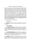
1
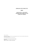
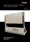
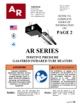
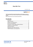
GLENSOUND CUB
BROADCAST USB/ iPhone AUDIO
INTERFACE
PRODUCT DETAILS
6 BROOKS PLACE, MAIDSTONE, KENT, ME14 1HE. ENGLAND.
Visit our Website at www.glensound.co.uk
TEL: +44 (0) 1622 753662
FAX: +44 (0) 1622 762330
Glensound Electronics Ltd
Thank you for choosing a new Glensound product.
All rights reserved.
Information contained in this manual is subject to change without notice, if
in doubt please contact us for the latest product information.
If you need any help with the product then we can be contacted at:
Glensound Electronics Ltd
1 – 6 Brooks Place
Maidstone
Kent
ME14 1HE
United Kingdom
Telephone: +44 (0) 1622 753662
Fax: +44 (0) 1622 762330
EMAIL ADDRESSES
General enquires: [email protected]
Technical enquires: [email protected]
Sales enquires: [email protected]
Page 2 of 26
PRODUCT WARRANTY:
All equipment is fully tested before dispatch and carefully designed to
provide you with trouble free use for many years.
We have a policy of supporting products for as long as possible and
guarantee to be able to support your product for a minimum of 10 years.
For a period of one year after the goods have been despatched the
Company will guarantee the goods against any defect developing after
proper use providing such defects arise solely from faulty materials or
workmanship and that the Customer shall return the goods to the
Company’s works or their local dealer.
All non-wear parts are guaranteed for 2 years after despatch and any
defect developing after proper use from faulty materials or workmanship
will be repaired under this warranty providing the Customer returns the
goods to the Company's works or their local dealer.
Page 3 of 26
CE
This equipment manufactured by Glensound Electronics Ltd of Brooks
Place Maidstone Kent ME14 1HE is CE marked and conforms to:
Low Voltage Directive: EN60065
Emissions: EN55103.1
Immunity: EN55103.2
WASTE ELECTRICAL AND ELECTRONIC
EQUIPMENT REGULATIONS 2006 (WEEE)
Glensound Electronics Ltd is registered for business to business sales of
WEEE in the UK our registration number is:
WEE/JJ0074UR
RoHS DIRECTIVE
EC directive 2002/95/EC restricts the use of the hazardous substances
listed below in electrical and electronic equipment.
This product conforms to the above directive and for this purposes, the
maximum concentration values of the restricted substances by weight in
homogenous materials are:
Lead
Mercury
Hexavalent Chromium
Polybrominated Biphenyls
Polybrominated Diphenyl Ethers
Cadmium
0.1%
0.1%
0.1%
0.1%
0.1%
0.01%
Page 4 of 26
GLENSOUND CUB USB/ iPhone AUDIO INTERFACE
Handbook Contents
Issue 1, July 2014
Description
Page No.
Contents
PRODUCT WARRANTY: .................................................................................................................................... 3
OVERVIEW ........................................................................................................................................................... 6
PANEL LAYOUT & FUNCTIONS....................................................................................................................... 7
ATTACHING A PHONE TO THE CUB............................................................................................................. 11
CONNECTING THE CUB TO PHONES/ PCS ETC .......................................................................................... 13
Connecting To iPhones With Lightning Connectors ................................................................................. 13
Connecting To iPhones With 30 Pin Connectors ...................................................................................... 14
Connecting To Android/ Windows Phones................................................................................................. 14
Connecting To A PC/ Mac ............................................................................................................................ 15
PC/ PHONE SOFTWARE INTERFACE TO CUB ............................................................................................. 16
SETTING UP AUDIO BETWEEN CUB & A PC ............................................................................................... 16
ASIO DRIVERS ................................................................................................................................................... 16
PROGRAMMING OPERATION OF ON/OFF BUTTONS ................................................................................ 17
AUDIO ROUTING CONFIGs ............................................................................................................................. 19
AUDIO ROUTING CONFIG BLOCK DIAGRAMS .......................................................................................... 20
AUDIO COMPRESSOR ...................................................................................................................................... 23
UPDATING FIRMWARE ................................................................................................................................... 24
BATTERY LIFE .................................................................................................................................................. 25
WIRING INFORMATION .................................................................................................................................. 26
Page 5 of 26
OVERVIEW
The Glensound CUB is a high quality audio interface for broadcasters. It is designed
to provide a very high quality bi-directional digital audio link into iPhones, iPads,
PCs, Macs and some Android phones. The mechanical design of the unit is highly
robust makig it ideal for portable use by journalists, reporters, engineers and
broadcasters.
The Glensound CUB is powered either from batteries (4 x AA cells) or an external
DC input. It does not supply power to recharge a mobile phone, this is because the
phones charging power requirement would fairly quickly flatten the batteries in the
CUB.
Internally the Glensound CUB is a highly sophisticated digital mixer, it has 2
analogue inputs both of which pass through high quality analogue to digital
converters and then these signals are handled and routed by the onboard DSP. This
DSP then provides a bi-directional stereo digital audio signal to: a USB audio
interface, a dedicated iPhone lightning connecter interface, a pair of analogue
balanced line outputs and 2 separate headphone amplifiers.
The digital audio link between the CUB and the connected device is a high quality
fully Broadcast specification 48kHz 24 bit interface. Devices such as the Apple
iPhone handle this audio format natively with no loss of audio quality.
Page 6 of 26
PANEL LAYOUT & FUNCTIONS
PLEASE NOTE AS THE UNIT IS CONFIGURABLE IT IS POSIBLE TO CHANGE THE OPERATION
OF SOME OF THE CONTROLS SHOWN HERE. THEREFORE THE FOLLOWING IS MEANT AS A
GUIDE ONLY.
6
7
-12 -6
0
9
ON
ON
+6
-12 -6
+6
0
L-BOTH-R
INPUT TYPE
MIC+PH
A
B
L-BOTH-R
MIXER
5
11
MIC
HEADPHONE MIX
L-BOTH-R
10
RIGHT
LEFT
g
glensound.co.uk
CUB
Reporters
interface
8
12
LINE
LEFT
A
BOTH
B
POWER
FLASHING =
LOW BATTERY
RIGHT
INPUT ROUTING
13
USB
File system
RETURN A
22
20
MIX
INPUT A
INPUT B
17
16
15
18
21
4
OUTPUT 1
RETURN B
19
14
23
OUTPUT 2
SERIAL No.000
W
USB
12V DC IN
CTR +VE
POWER ON
CE
INPUT A
INPUT B
HEADPHONES
PHANTOM POWER = 48V
3
2
1
29
28
27
26
25
24
g
www.glensound.co.uk
Glensound CUB Battery cover
1. Power On/ Off Switch
Turns the CUB on/ off.
2. XLR Balanced Line Output 2
This balanced standard 3 pin XLR audio output plug provides an analogue output of
its associated source. (Factory default this is a mono mix of the return audio from the
USB source)
3. XLR Balanced Line Output 2
This balanced standard 3 pin XLR audio output plug provides an analogue output of
its associated source. (Factory default this is a mono mix of the mix audio being sent
to the USB device)
4. USB Audio Connector
This is a standard mini USB connector. It provides only a digital audio interface to/
from a connected device such as PC/ Mac, Android Phone and older style iPhones.
Page 7 of 26
5. Power On LED
This LED indicates that the unit is turned on. If running from batteries it also indicates
if the batteries are getting towards the end of their life. When running from batteries if
the LED is permanently on then the batteries are good, if the LED is flashing the
batteries are running low and need to be changed soon. The quicker the flash the
lower the batteries are running and the sooner they need changing.
6. Left PPM
This small 4 LED meter, has characteristics similar to a peak programme meter
(PPM). The numbers printed underneath the LEDs indicate the equivalent analogue
level in dB where 0dB = -18dBFS. By default this meter indicates the level of the
audio being sent to the left channel of the stereo USB interface.
7. Right PPM
This small 4 LED meter, has characteristics similar to a peak programme meter
(PPM). The numbers printed underneath the LEDs indicate the equivalent analogue
level in dB where 0dB = -18dBFS. By default this meter indicates the level of the
audio being sent to the right channel of the stereo USB interface.
8. Input A ON/ OFF Button
This switch turns input A on /off. How this button operates (i.e. always on, latching
on/off, cough etc.) can be changed see ‘Programming operation of ON/OFF buttons’
for further details.
9. Input B ON/ OFF Button
This switch turns input B on /off. How this button operates (i.e. always on, latching
on/off, cough etc.) can be changed see ‘Programming operation of ON/OFF buttons’
for further details.
10. Input A Mic/ Line/ Mic + PH Switch
This 3 position switch adjusts the input gain, source impedance and turns phantom
power on/ off to allow the associated XLR input to accept a full range of signal levels.
The graphical representation of the switch positions on the panel show the various
states of the switch.
11. Input B Mic/ Line/ Mic + PH Switch
This 3 position switch adjusts the input gain, source impedance and turns phantom
power on/ off to allow the associated XLR input to accept a full range of signal levels.
The graphical representation of the switch positions on the panel show the various
states of the switch.
Page 8 of 26
12. Input A Left/ Both/ Right Routing Switch
This 3 position switch routes the A input to stereo output. It can route the audio to
either the left channel only, right channel only or both channels (left & right equally).
The printing on the panel next to switch indicates the routing relative to the switches
position. ** Please note that the routing can be changed in the devices configuration
settings.
13. Input B Left/ Both/ Right Routing Switch
This 3 position switch routes the A input to stereo output. It can route the audio to
either the left channel only, right channel only or both channels (left & right equally).
The printing on the panel next to switch indicates the routing relative to the switches
position. ** Please note that the routing can be changed in the devices configuration
settings.
14. USB File System
The front panel mini USB File System connector is used for updating the devices
firmware and software and loading configuration files. No digital audio is present on
this connector.
15. Input B Gain Control
The rotary potentiometer adjusts the input gain of the B input. Turning it right will
increase the gain and therefore increase the audio level that you are sending to the
outputs and turning it to the left will reduce the gain/ level.
16. Input A Gain Control
The rotary potentiometer adjusts the input gain of the B input. Turning it right will
increase the gain and therefore increase the audio level that you are sending to the
outputs and turning it to the left will reduce the gain/ level.
17. Mix Headphone Volume
This volume pot adjusts the audio level of the mix output to the headphone
amplifiers. It does not adjust the mix level to the USB circuit.
18. Mix Headphone L-BOTH-R Routing
This 3 position switch routes the headphone mix circuit to either the left only, right
only or both (left & right) channels of the headphone amplifier. Note as the mix circuit
is normally stereo the default setting is to send stereo to the headphones when the
switch is in the BOTH position, and a mono mix of the stereo circuit if the switch is in
the L or R position.
19. Return B Headphone Volume
This volume pot adjusts the audio level of the B leg of the return audio from the
attached USB device.
Page 9 of 26
20. Return B Headphone L-BOTH-R Routing
The 3 position switch routes the incoming B leg of the audio from the attached USB
device to either the Left only, Right only or Both (left and Right equally) channels of
the headphone amplifier.
21. Return A Headphone Volume
This volume pot adjusts the audio level of the A leg of the return audio from the
attached USB device.
22. Return A Headphone L-BOTH-R Routing
The 3 position switch routes the incoming A leg of the audio from the attached USB
device to either the Left only, Right only or Both (left and Right equally) channels of
the headphone amplifier.
23. 6.35mm Professional Headphone Jack Socket
Connect headphones here. This headphone output is suitable for both professional
high impedance (200 – 2000 Ohm) and domestic low impedance (16 – 32 Ohm)
headphones. It is wired a standard stereo headphone circuit. The two headphone
jack sockets are both driven from their own independent headphone amplifiers.
24. 6.35mm Professional Headphone Jack Socket
Connect headphones here. This headphone output is suitable for both professional
high impedance (200 – 2000 Ohm) and domestic low impedance (16 – 32 Ohm)
headphones. It is wired a standard stereo headphone circuit. The two headphone
jack sockets are both driven from their own independent headphone amplifiers.
25. Input B XLR Balanced Audio Input
This balanced standard 3 pin XLR audio input socket is the input for the B channel of
the mixer. **Note the routing of the channel can be altered by loading a different
config.
26. Input a XLR Balanced Audio Input
This balanced standard 3 pin XLR audio input socket is the input for the a channel of
the mixer. **Note the routing of the channel can be altered by loading a different
config.
27 & 28. Battery Compartment Screw
Finger operated screw for removing battery cover.
29. External DC Input
This is a 2 pin barrel type DC input connector. The centre pin is 2.5mm. It is wired
centre pin + Volts. It is designed to accept a + volt DC input between 9 and 15 volts.
Page 10 of 26
ATTACHING A PHONE TO THE CUB
1. General
If you want to attach your phone to the CUB rather than have it positioned away from
it then there are 2 options for this.
IMPORTANT *****If you attach your phone to the CUB it is your responsibility to
check that it is held securely and you are happy that your phone will not get dropped
or broken. If you are in any doubt as to the secureness of the attachment you should
not use it and make other arrangements that you are happy with. Glensound will not
accept any responsibility if your phone is damaged during/ after attachment to the
CUB. It is entirely up to you to make sure that your phone does not get damaged*****
2. Using The Micro Sucker Pad
The material attached to the top of the CUB has thousands of microscopic craters
that work by creating many partial vacuums between it and the attached device.
It only works with smooth surfaces. For example the standard finish of an iPhone 5 is
a flat smooth surface and works well. However if the iPhone 5 is in a protected case
which is not smooth and flat it will not work at all.
When your CUB ships from the factory this material has a protective film on it to stop
the microscopic craters getting dirty. This protective film should be removed prior to
use.
To attach your smooth sided phone to the micro sucker pad, just place your phone in
the desired position on the pad and then give it a firm press down, this makes sure
that the suckers can do their job.
Once attached make sure you are happy that your phone is held correctly and
cannot fall of by accident. It is your responsibility to make sure your phone does not
get damaged!
To remove the phone the best technique is to gently prise off one corner.
IMPORTANT****The Micro Sucker pad must be clean to work correctly. If it gets dirty
it will not be able to hold the phone correctly. If it is dirty it can be cleaned by wiping
with a damp cloth and left to air dry.
IPhone Attached using the Micro Sucker Pad.
Page 11 of 26
3. Using The Bands
An alternative solution to the Micro Sucker Pads are bands. These provide a solution
if your phone is not flat or is in a case that does not have a smooth surface.
To use the bands simply place your phone on top of the CUB and then stretch the
bands across the phone and attach each end to the attachment points as per the
photograph.
Once your phone is attached it is your responsibility to make sure that it is firmly
secure and will not get damaged during use. If in doubt you should not attach the
phone to the CUB.
IPhone attached to CUB using bands.
Page 12 of 26
CONNECTING THE CUB TO PHONES/ PCS ETC
There are a number of different ways of connecting the CUB to devices such as
PCs, Phones, iPads etc.
Supplied with the CUB are a full set of interface cables to allow connection to as
many different devices as possible.
Connecting To iPhones With Lightning Connectors
As shown in the above picture the supplied long thin converter should be used to
connect to an iPhone/ iPod/ iPad with a lightning connector. The long thin converter
should be inserted in the opening on the top of the CUB and it should be plugged
into the USB plug located there. Please note the long thin converter has a USB
socket on it and as such it can only be inserted one way up.
If you want to connect a device with a lightning connector and locate it further away
from the CUB then connect the long thin converter directly to the iPad etc. and use a
mini USB cable to USB A cable and connect it as shown in the picture below.
Page 13 of 26
Connecting To iPhones With 30 Pin Connectors
As shown in the above picture the supplied short fat converter and mini USB to
USB A cable should be used to connect to an iPhone/ iPod/ iPad with a 30 pin
connector.
Connecting To Android/ Windows Phones
Android & Windows phones have a USB connector that is the same size a micro
USB but for correct connectivity an ‘On the Go’ cable should be used. Supplied with
the CUB is a mini usb to ‘On the Go’ cable for connecting to Android/ Windows
devices.
PLEASE NOTE: Currently windows phones do not support digital USB audio and
therefore cannot be used with the CUB. Please check our web site for updates. Only
a limited number of Android phones currently correctly support USB digital audio,
see our web site for an up to date list of compatible devices.
*****The htc phone in the picture is for illustration purposes only and is a windows
phone and as such is not currently compatible.
Page 14 of 26
Connecting To A PC/ Mac
As shown in the above picture, connect the CUB to a PC using the mini USB socket
on the side of the device.
Connecting To An iPad
When connecting to an iPad either the short fat converter or the long thin converter
will be needed. Then connect the USB A socket of the converter to the mini USB
socket on the side of the CUB as per the above photo.
Page 15 of 26
PC/ PHONE SOFTWARE INTERFACE TO CUB
1. General
After you have made the physical connection between the CUB and PC/ Phone etc
and you have turned the CUB on, the device that it is connected to will automtically
detect it.
2. iPhone/ iPad
Once the CUB is on and connected to an iPhone the iPhone will automtically turn it’s
internal mic and speaker off and select its audio source as USB Audio (i.e. the CUB).
3. Android Phone
Once connected most Android Phones just automtically switch off their internal mic
and speaker and use the CUB as the audio source.
SETTING UP AUDIO BETWEEN CUB & A PC
1. USB 1 Drivers
Connecting the unit to the PC as described above will automatically install suitable
USB class 1 drivers for interfacing with Windows. Windows should automatically set
it’s audio I/O to become ‘Glensound USB audio 1.0’ if it doesn’t then search the pc or
goto ‘Manage Audio devices’ or ‘Sound’ and manually select ‘Glensound USB audio
1.0’ and set it to default.
2. Software Audio I/O selection.
Most audio software programs will set their audio I/O as per the windows default
audio I/O selection. However if you experience problems check that the software that
you are using has it’s audio I/O set to ‘Glensound USB audio 1.0’
ASIO DRIVERS
1. General
USB audio 1.0 drivers are good because they normally just work within windows and
no manual driver installation is required. However all audio into and out of your pc
will go through windows processing, this adds delay and provides potential pitfulls
(such as having the volume turned down within windows). ASIO (Audio Stream Input
Output) drivers bypass windows processing and offer a direct link between the
software and soundcard (in this case the CUB). ASIO drivers are generally considerd
to be far better for professional users than USB audio 1.0 drivers.
2. ASIO4ALL
The USB audio chipset that we selected for use in the CUB is suitable for use with a
free ASIO driver called asio4all. Just search the web for ‘asio4all’ and you will find
links to the drivers and installation guides.
Page 16 of 26
PROGRAMMING OPERATION OF ON/OFF BUTTONS
The operation of the input A and B channels ON/ OFF buttons can be set by the user
to meet their own requirements. For example the buttons could be set to be always
on and operate as a Cough switch when pushed, or they could operate in a latching
on/ off mode; all the possibilities are detailed below.
As well as the operation of the buttons the interaction of the buttons with one and
other can also be set by the user. This interaction can be set individually for each
button.
To Change The Operation of The Buttons:
1) Enter Programming Mode:
Switch on while holding down both A and B channel ON/OFF buttons. The LEDs in
the A and B buttons will start to flash to indicate that you are in programming mode.
2) Knowing What The Current Mode Is:
Whilst in programming mode the 2 x 4 LED PPMs indicate the current state. The left
PPM indicates the state of input A ON/OFF button and the right PPM indicates the
state of input B ON/OFF button.
3) Changing Mode:
Each push on the ON/OFF button will select the next mode of operation.
4) Modes and Their Indication:
LED POSITION
BUTTON OPERATION
-12
Normally OFF, momentary ON
-6
Latching ON/ OFF
0
Intelligent Lever Key, quick push to latch, long push for
momentary
+6
Normally ON, momentary OFF (Cough Switch Operation)
-12 & -6
Latching ON/OFF, While holding switch down input is routed to
other output (i.e. Talkback mode)
****TALKBACK MODE NOTE
When in talkback mode, the audio routing is automatically changed to a talkback
configuration.
Programme audio is always routed to the left channel of the USB and Talkback is
always routed to the right channel of the USB.
****The front panel input routing switches are bypassed when in talkback mode and
have no effect.
Audio routing to the local analogue outputs can be altered. By default Programme
audio appears on output A and return USB A audio appears on output B. To change
the routing to the analogue outputs follow the instructions in the text file called
‘Alternative Talkback settings’ which can be found using windows explorer on the
CUBs filing system.
Page 17 of 26
To Change The Interaction of The Buttons:
1) Enter Programming Mode:
Switch on while holding down either A or B channel ON/OFF buttons. The LED in
the selected button will start to flash to indicate that you are in programming mode
for that button.
2) Knowing What The Current Mode Is:
Whilst in programming mode the 2 x 4 LED PPMs indicate the current state. The left
PPM indicates the state of input A ON/OFF button and the right PPM indicates the
state of input B ON/OFF button.
3) Changing Mode:
Each push on the ON/OFF button will select the next mode of operation.
4) Modes and Their Indication:
LED POSITION
WHEN ON/ OFF BUTTON IS PRESSED
-12
No effect to the other channel
-6
While the button is in its ON state, the other button is turned
OFF. When ON state is changed back to OFF, the other button
will resume its original state
0
While the button is in its ON state, the other button is turned
OFF. When ON state is changed back to OFF, the other button
will remain OFF
+6
Not currently used
Page 18 of 26
AUDIO ROUTING CONFIGs
1. General
The Glensound CUB has a powerful audio dsp (digital signal processor) at its heart.
All the analogue audio inputs and outputs to the unit are converted to digital and are
controlled by this dsp. This means routing of the audio internally can be changed to
meet your requirements.
2. Location of Config Files
The audio routing config files are stored on the internal drive. Using file explorer
locate the drive called CUB (your pc must be connected via the front mini USB
connector marked ‘USB File system), in this drive you will see a number of folders all
starting with the name ‘Config’ followed by a description, for example ‘Config Dual
Mono Local Cue outs’. Each of these folders has in it a single text file called
‘settings’.
3. Selecting Which Config File To Use
When the CUB first turns on it reads a file called ‘Selected config’ which is a text
document and can be found using file explorer in the CUB drive. This ‘Selected
config’ text file tells the CUB which config to use.
To change the config simply open the ‘Selected config’ text file (we’d use Notepad,
but other text editors can be used, however once modified it must continue to be
saved as a .txt file), then change the wording of the text file to match exactly the
folder name of the config file you want to use, then save the modified file but keep
the name ‘Selected config’.
After modifying the file to start using the new config the CUB must be turned off and
on again.
4. Default Config
When leaving the factory the GS-GC5/USB ‘Selected config’ file will be set to default.
The default config is one that cannot be changed and is permananetly embedded in
the dsp. It’s functions are broadly the same as the config called ‘default. The purpose
of the default config file is to allow the CUB to still work even if no Config folders are
present.
Page 19 of 26
INPUT B
INPUT A
MIC
LINE
MIC + 48v
MIC
LINE
MIC + 48v
SET GAIN
SET GAIN
GAIN
GAIN
L/BOTH/R
L/BOTH/R
ON/OFF
ON/OFF
SIMPLIFIED GLENSOUND CUB
DEFAULT AUDIO BLOCK DIAGRAM
MIXER
PPM
PPM
HEADPHONE VOLUME
LINE OUTPUT 1
L/B/R Switching
LINE OUTPUT 2
MIX RIGHT
MIX LEFT
RETURN B
RETURN A
HEADPHONES
HEADPHONES
HEADPHONE AMPS
MINI USB 'SIDE SOCKET' &
LIGHTNING 'TOP CONNECTOR'
IN PARALLEL WITH EACH OTHER
AUDIO ROUTING CONFIG BLOCK DIAGRAMS
Page 20 of 26
Page 21 of 26
INPUT B
INPUT A
MIC
LINE
MIC + 48v
MIC
LINE
MIC + 48v
SET GAIN
SET GAIN
GAIN
GAIN
L/BOTH/R
L/BOTH/R
ON/OFF
ON/OFF
MIXER
SIMPLIFIED GLENSOUND CUB
STEREO RETURN OUT AUDIO BLOCK DIAGRAM
PPM
PPM
HEADPHONE VOLUME
L/B/R Switching
LINE OUTPUT 2
LINE OUTPUT 1
MIX RIGHT
MIX LEFT
RETURN B
RETURN A
HEADPHONES
HEADPHONES
HEADPHONE AMPS
MINI USB 'SIDE SOCKET' &
LIGHTNING 'TOP CONNECTOR'
IN PARALLEL WITH EACH OTHER
Page 22 of 26
INPUT B
INPUT A
MIC
LINE
MIC + 48v
MIC
LINE
MIC + 48v
SET GAIN
SET GAIN
GAIN
GAIN
L/BOTH/R
L/BOTH/R
ON/OFF
ON/OFF
MIXER
SIMPLIFIED GLENSOUND CUB
STEREO LOCAL OUT AUDIO BLOCK DIAGRAM
PPM
PPM
HEADPHONE VOLUME
L/B/R Switching
LINE OUTPUT 2
LINE OUTPUT 1
MIX RIGHT
MIX LEFT
RETURN B
RETURN A
HEADPHONES
HEADPHONES
HEADPHONE AMPS
MINI USB 'SIDE SOCKET' &
LIGHTNING 'TOP CONNECTOR'
IN PARALLEL WITH EACH OTHER
AUDIO COMPRESSOR
The CUB has 2 compressors 1 for each input. These compressors are handled in
the DSP in the digital domain.
By default the compressors are turned on when the input is switched to Mic or Mic +
Phantom Power and they are switched off when the input is switched to Line
(because the Line source should be a controlled one). There is a simple limiter built
onto the ‘off’ setting when the input is switched to Line to save the digital signal going
above full scale.
It is possible to turn the compressor on/ off using a different config file, please
contact Glensound for more information.
As the compressor is done in the DSP it is also possible to change its
characteristics, again please contact Glensound for more information.
In the above compressor plot of the CUBs default compressor the horizontal axis is
the input level and the vertical axis is the output level.
Page 23 of 26
UPDATING FIRMWARE
The firmware is the code that runs internally in the CUB and provides the structure of
the internal DSP and Microcontroller. The firmware can be updated easily without the
need to return the CUB to Glensound. You should only ever update the firmware if
instructed to by a Glensound engineer.
How To Update The Firmware:
1) Connect the CUB to your PC using the front panel mini USB connector
(marked as USB File system)
2) Turn on the CUB.
3) Your PC will automatically detect the CUB, load drivers and then it should be
possible to locate the CUB directory using a file explorer (i.e. Windows
Explorer).
4) The new firmware file will be provided to you by a Glensound engineer. Its file
name will be ‘application.bin’.
5) Drag and drop the ‘application.bin’ file into the CUB directory using your file
explorer.
6) Turn the CUB off and on again.
7) The firmware will now have been updated.
Page 24 of 26
BATTERY LIFE
When running from batteries there are a number of things that effect the duration
and life of the batteries.
1) Brand & Type Of Battery
Not all batteries are equal in the amount of energy that they store. In fact they vary
hugely. A battery that does not store much energy will of course not keep the CUB
running as long as one that stores a lot of energy.
Traditionally Alkaline batteries have always been the choice of Broadcasters, and we
still recommend them over most other battery types, however now they are
commonly available Lithium Ion batteries are a very good choice and generally far
exceed alkaline batteries.
In a test which involved running 1 pair of high impedance headphones at high
volume, 1 mic input & 1 line input with programme audio on the line input Procell
Alkaline batteries lasted 3 hours 3 minutes & Energizer Ultimate Lithium batteries
lasted 7 hours 45 minutes.
A very good website providing a huge range of comparisons between different
brands of batteries and well worth a visit is: www.batteryshowdown.com
2) Temperature
The energy from batteries dissipates much quicker at lower temperatures. Using the
CUB (or any battery operated equipment) in very cold temperatures will greatly
reduce battery life.
3) Phantom Power
Microphones that require Phantom power drain energy from the internal batteries.
Phantom power is +48 Volts, so although the headline figure of for example 6 mA
current requirement of a phantom powered microphone may not seem too great,
once this has been converted down to the maximum 6 Volts available from 4 x AA
cells, the current drain shoots up!
Therefore for best results use a dynamic microphone that does not need Phantom
Power.
4) Headphone Impedance
Traditionally the impedance of the headphones that you use will make a huge
difference to battery life, with low impedance headphones taking much more current
from a circuit designed to run broadcast spec high impedance headphones. This
however is not a problem for the CUB. You can safely use high or low impedance
headphones without any detrimental effect of the battery life.
Page 25 of 26
WIRING INFORMATION
2
1
STANDARD XLR AUDIO PINOUTS:
3
1: Ground/ Earth
XLR SOCKET (FEMALE)
2: INPHASE/ POSITIVE/ MIC +
3: MATE/ NEGATIVE/ MIC -
1
2
3
STANDARD HEADPHONE WIRING:
XLR PLUG (MALE)
TIP: A/ LEFT Ear
RING: B/ RIGHT Ear
SLEEVE: Common/ Earth
RING
TIP
SLEEVE
CUB External DC power input: 2.5mm Barrel, Centre +Ve, 9 to 15 Volts, 1 Amp
Page 26 of 26