1
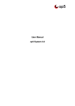
HOLLAND
ELECTRONICS LLC
Model ST5120 Hand - Held Field Strength Meter
USER’S MANUAL
Features:
•
Selects Channels 2 – 135 CATV
2 – 79 Off-Air
Direct Frequencies 46-870 MHz using
Simple up/down arrow keys
•
Measures Visual, Aural, or V-A
•
Wide Dynamic Range (-35 to +60 dBmv)
•
AC Voltmeter
•
8 Hour Rechargeable NiMH battery
•
Adjustable Channel Volume
•
Auto Power Shut-Off, Battery Status Indicator
In dBmv or dBuv (selectable)
Table of Contents
Introduction……………………………………………………………………………….3
Specifications……………………………………………………………………………..3
External Features…………………………………………………………………………4
Keypad Controls………………………………………………………………………….5
Powering the Meter………………………………………………………………………6
Signal Measurement……………………………………………………………………...6
Operation…………………………………………………………………………………7
Selecting USA CATV or UHF/UHF inputs……………………………………………...7
Selecting Video, Audio, or V-A measurement modes…………………………………..7
Power Level measurement in Frequency mode………………………………………….8
Volume level and LCD contrast adjustment…………………………………………….8
AC Voltage Measurement………………………………………………………………8
Care and Maintenance…………………………………………………………………..8
Warranty Information…………………………………………………………………...9
Introduction
The ST5120 hand-held Field Strength Meter uses RF signal processing techniques in
combination with microprocessor technology to produce quick and accurate signal
measurements. The meter provides the user a choice of reading individual channel video,
audio, or a-a power level measurements. Automatic/semi-automatic internal calibration
corrects for measurement variations due to frequency response, temperature change and
internal attenuator setting. The combination of keypad tuning and menu driven display
allow for simple operation.
The meter is programmed with both USA CATV and UHF/UHF NTSC standard formats.
Users can also select frequencies for signal testing. The backlit LCD allows for viewing
signal measurements even in dark places.
Specifications
Input Frequency Range
Channels 2 – 135 CATV
Channels 2 – 78 Off – Air
Frequency Stability
Resolution
Input Impedance
46-870 MHz
30 ppm
50 KHz
75
Power Level Testing
Range
Accuracy
Resolution
-35 - +60 dBmV
± 2.5 dBmV
0.1 dBmV
AC Voltage Testing
Input Range
10 – 100 vac
Channel Type
NTSC (6 MHz)
Input Connector
LCD Controls
Screen Size
Replaceable High Return Loss F Type
Contrast, Back Lighting
60 * 17 mm
Features
Audio
Illumination
AC Input
Battery use
Size (mm)
Weight
Adjustable Volume
Back-Lit LCD
110V / 60Hz
8 Hours Minimum Charge
210 * 93 * 50
0.5 Kg
Keypad Controls
See fig. 1.1 to locate the following keypad controls.
1.
– Power on/off button.
2.
CH – Selects Video, Audio and V-A carrier measurement modes. Default is Video
carrier mode. In any carrier mode the buttons can be used for stepping to the
desired channel.
3.
MHz – Changes the Channel selective mode to Frequency mode. The buttons
can be used for stepping to the desired frequency.
4.
SYS – used with the keys to select either CATV or VHF/UHF inputs and either
dBmV r dBuv measurement units.
5.
– Backlight on/off
Note: Using the backlight will discharge the battery more rapidly.
It is recommended that you select this function only when necessary.
6.
– Selects contrast of volume adjustment.
7.
– AC Power measurement mode.
8.
- Used to increment or decrement channel or frequency. Also to adjust volume
level or LCD display contrast. Also used to select between CATV or UVH/UHF
units, and dBmV or dBuv measurement units.
Other Physical Features
9.
F-Type input connection.
10.
Audio Speaker
11.
DC power jack for power adapter.
12.
Pilot LED to show meter charging.
13.
LCD display
Powering the meter
The digital signal level meter can be powered by either an external AC voltage source or
by the internal rechargeable NiMH batteries.
A) Using an external AC source – make sure that the available AC line voltage
is 120V, 60 Hz. Connect the DC output lead from of the adapter/ charger to
the DC jack at the bottom of the ST5120 meter. Plug the adapter / charger
into a 110vac source.
B) Powering the meter with internal batteries: In order for the ST5120 meter to
operate from the internal batteries, a sufficient charge must exist on the
batteries. The recommended charging time for low charged batteries is 8
hours. Charging the batteries occurs when the charger is used to power the
meter from an external AC source. The batteries charge whether the meter is
switched on or off. The meter will alarm and flash the word “BAT” on the
display to indicate low battery power. The meter will automatically shut
down if idle for more than 5 minutes.
Signal Measurement
1) The RF signal input port is a type F male connector. Please use the G-F81 type
adapter supplied by the meter.
When connecting the G-F81 type adapter, first align the threads. Carefully screw in the
adapter until seated. Over tightening can seriously damage the input port.
2) The ST5120 hand-held TV/CATV Analyzer has TWO basic measurement modes,
Channel power level measurement and Frequency power level measurement. Both
modes can make measurements as follows:
CHV Video Carrier
CH
Measurement Mode
CHA Audio Sub-Carrier
Measurement Mode
CH
CH
V/A Ratio
Measurement Mode
Operation
1. Press the
button to turn on meter. The meter will start up with the model number
and serial number, then automatically enter into the Video/Audio carrier measure mode.
2. System Setting: The ST5120 offers the options of measuring either USA CATV or
UHF/UHF channels. Press the SYS key to select the menu. Use the key to select
either CATV or VHF/UHF mode. Use the key to select either dBmV or dBuv
measurement units. Once set; press the SYS key again to exit and store the setting
values as the default.
CATV
dBmV
VHF/UHF
dBuv
Press to select
Between CATV and
VHF/UHF
Press to select
Between dBmv and
dBuv
3. Video, Audio and V-A differential measurement in Channel Mode: Press the CH
key to toggle between Video (CHV) , Audio (CHA), or V-A differential (V-A)
modes.
Use the keys to select the desired channel.
134 CHV
50.7 dBmv
853.25 MHz
134 CHA
857.75 MHz
134 CH
V-A
17.8 dBmV
32.9 dBmV
4. Power Level Measurement in Frequency Mode: Press the MHz key to enter the
Frequency Power Level measurement mode. Select the desired frequency by using
the keys. (Note that the cursor will be moved to the right of “MHz”).
134 CH
50.7 dBmv
853-25 MHz
Fig. 4.1 a
??? CH
50.4 dBmV
855.25 MHz
Fig. 4.1 b
If the frequency selected is not on the Standard Channel Table, the display will show ???
as the CH number. (see fig. 4.1b)
To return to channel measurement mode, press the SYS key twice.
5. Volume and LCD contrast level adjustments: In the Channel or Frequency Power
Level measurement modes, press the
button to choose between Volume or
Contrast level adjustment. Adjust the Volume or Contrast levels using the keys.
6. AC voltage measurement: Press the
key to enter the Voltage measurement
mode. The input range is 10 – 100 vac. The meter will alarm if the input exceeds 100
vac. Exit this mode by pressing the
key again.
AC – VOLT
AC – VOLT
100.0 V
60.0 V
Care and Maintenance
1. Please keep the meter clean and dry. Don’t place the meter in a harmful environment
(dust, acid, alkali or moisture). Never clean the surface of the meter with organic
solvent, acid or alkali solvent.
2. Avoid vibrating the meter. Never allow an external force to press against the LCD
window, so as not to damage the display screen.
3. Do not drop the meter
4. Do not over tighten the G-F81 type connector at the input port.
5. When charging, use only the special charger supplied with the meter. Fully charge
the batteries at least once every six months if not in use for an extended period.
HOLLAND ELECTRONICS LLC
LIMITED WARRANTY
Holland Electronics LLC, warrants that the product enclosed with this Limited Warranty
statement will conform to the manufacturer’s specifications and be free of defects in the
workmanship and material for a period of one-year (1) from the date of original purchase.
WARRANTY PROCEDURE:
If the product appears to be defective contact Holland Electronics LLC at (805) 3399060. We will analyze the problem and offer solutions to prevent removing the unit from
service. If no solution is found, and the unit must be returned for repair, you will be
issued a Return Authorization (RA) number.
Holland Electronics LLC will, at its option, repair or replace the defective unit under
warranty, without charge for parts or labor. This repair will be subject to charges if signs
of tampering or misuse are detected. Incoming shipping costs will be the customer’s
responsibility. Returns will not be accepted without an RA number.
The warranty and remedy provided above are exclusive and in lieu of all other express
warranties and unless stated herein, any statements or representations made by any other
person or firm are void. The duration of any implied warranties of merchantability or
fitness for a particular purpose on this product shall be limited to the duration of the
warranty set forth above. Except as provided in this written warranty, Holland
Electronics LLC shall not be liable for any loss, inconvenience, damage, including direct,
special, incidental, or consequential damages, resulting from the use or inability to use
this product, whether resulting from breach of warranty or any legal theory.
Some states do not allow limitations on how long an implied warranty lasts and some
states do not allow the exclusion or limitation of incidental or consequential damages, so
the above limitation and exclusion may not apply to you.
The warranty gives you specific legal rights, and you may also have other rights which
vary from state to state.
To arrange for warranty service: Call Holland Electronics LLC (805) 339-9060
Return Address with appropriate Return Authorization Number:
2935 Golf Course Drive
Ventura, CA 93003