1
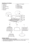
www.thegaragedoorcentre.co.uk 5048551A-GB 26/04/07 14:36 0800 525 442 www.thegaragedoorcentre.co.uk Page 1 GENERAL PRESENTATION 2 SAFETY INSTRUCTIONS 2 Caution Safety instructions 2 2 PRODUCT DESCRIPTION GB CONTENTS 2 Product components Types of door 2 2 POINTS TO CHECK PRIOR TO INSTALLATION 3 Preliminary checks Safety instructions 3 3 INSTALLATION 3 Installation height Detailed description of installation steps 3 3 PROGRAMMING 5 Programming button description Learning Memorising remote controls 5 5 5 OPERATING TEST 5 Using the remote controls Obstacle detection function Built in lighting operation 5 5 6 CONNECTING PERIPHERALS 6 Description of the various peripherals Electrical connections for the various peripherals 6 6 SETUP 7 Setup general diagram Definition of the different settings 7 7 SPECIAL OPERATION 8 CLEARING REMOTE CONTROLS AND ALL SETTINGS 8 Clearing remote controls Resetting all settings 8 8 TROUBLESHOOTING 8 Operating codes displayed Programming codes displayed Error and failure codes displayed Accessing stored data 8 9 9 9 TECHNICAL SPECIFICATIONS 10 1 www.thegaragedoorcentre.co.uk 0800 525 442 www.thegaragedoorcentre.co.uk www.thegaragedoorcentre.co.uk 5048551A-GB 26/04/07 0800 525 442 14:36 www.thegaragedoorcentre.co.uk Page 2 GENERAL PRESENTATION GB This product complies with the “safety, specific rules for powering vertically opening garage doors in residential use” requirements (standard EN 60335-2.95). When installed in line with these instructions and in compliance with the “Installation Checklist”, the product will be compliant with standards EN 13241-1 and EN 12453. The instructions referred to in the installation manual and instructions for use of this product are designed to prevent damage to property and personal injury along with compliance with the above standards. Failure to comply with these instructions absolves Somfy from any liability resulting from damage that may be caused. Dexxo Pro is a product that must be installed inside the garage with an integrated back-up control system. Somfy hereby declares thatthe device is compliant with the essential demands and other relevant requirements of directive 1999/5/CE. A declaration of compliance is available from the web site at www.somfy.com/CE (Dexxo Pro). This product is suitable for use in the European Union and in Switzerland. SAFETY INSTRUCTIONS Caution These are important safety instructions. Always follow the instructions, incorrect installation may lead to serious injury. Safety instructions Before installing the motor drive unit, remove all unessential lines or chains and switch off all equipment that is not essential for motorised door operation. Before installing the motor drive unit, make sure that the door is in good mechanical condition, that it is properly balanced and that it opens and closes correctly. Locate all control systems at least 1.5 metres above floor level, making sure that they are visible from the entrance to the garage but safe from moving parts. Position the manual release cord no more than 1.8 metres above floor level. Where a removable release mechanism is used, we recommend storing it close to the door. Fix the label describing the manual release procedure close to the release mechanism. Fix the warning labels describing the hazards of door motion close to any fixed control mechanisms installed and make sure that the labels are clearly visible to the user. After installation, make sure that the mechanism is correctly adjusted and that the motor drive unit reverses its motion when the door encounters an obstacle that is at least 50 mm from floor level. After installation, make sure that no part of the door overhangs an area accessible to the public. After installation, make sure that the motor drive unit inhibits or stops the door opening motion when the door is loaded down with a 20 kg weight attached to a central position of the door’s bottom edge. PRODUCT DESCRIPTION Product components Fig. 1 Key 1 2 3 4 5 6 7 8 9 10 11 12 13 Number 1 1 1 1 1 2 2 1 1 2 4 1 2 Description Motor head Motor cover Built-in light cover Lintel bracket Door bracket Ceiling bracket Motor head bracket Manual release cord Link arm Travel stop Chain retainer pad Power cable Hex. head M8x16 bolt Key 14 15 16 17 18 19 20 21a 21b 21b1 21b2 22 23 Number 4 6 2 2 4 4 2 1 1 1 8 2 1 Description Hex. head M8x12 bolt & washer HU8 nut Shaft Circlips Self-tapping φ 3x10 screw Self-shaping φ 4x8 screw Special screw for plastic φ 3.5x12 Single part rail Two part rail Sleeve Self-shaping φ 4x8 screw Keytis remote control 230 V 40 W E14 socket light bulb Types of doors Fig. 2 A: Projecting up and over door. B: Sectional door. If the door surface exceeds 10 sq. metres or if the upper profile is a specific one, use the sectional door kit, ref.: 2400650. C: Swinging door. Use the swinging door kit, ref.: 2400459. D: Semi-projecting up and over door (canopy door). Use the semi-projecting up and over door kit, ref.: 2400458. 2 www.thegaragedoorcentre.co.uk 0800 525 442 www.thegaragedoorcentre.co.uk www.thegaragedoorcentre.co.uk 5048551A-GB 26/04/07 14:36 0800 525 442 www.thegaragedoorcentre.co.uk Page 3 Door dimensions (Fig. 3) For maximum door heights, the motor travel can be optimised: . By installing the motor head at a 90° angle (AAbb. 7- ). . By fixing the lintel bracket to the ceiling, behind the lintel itself by up to 200 mm (AAbb. 5- ). . By cutting the link arm to size. GB POINTS TO CHECK PRIOR TO INSTALLATION Preliminary checks Check the garage door can be operated manually and runs smoothly. Ensure the door is in good mechanical condition (pulleys, mounts…) and is correctly balanced (spring tension). Remember that any work performed on door springs may be dangerous. The structure of your garage (walls, lintel, inside surfaces, cross members, door rails…) are used to mount the Dexxo Pro system. Reinforce them where necessary. Never splash water onto the system. Never install Dexxo Pro in a location where water may cause damage. The bottom edge of the door should be fitted with a rubber strip to avoid hard contact and enhance the contact surface. If the garage door is the only entry point into the garage, fit an external release (external release keylock (ref. 9012961) or an external release (ref. 9012962) and include a back-up battery (ref. 9001001). If the garage door includes a separate pedestrian door, the door must be fitted with an interlock to prevent garage door movement when the pedestrian door is open (pedestrian door safety kit ref. 2400657). If the garage door opens on to a public road, install an indicator light, such as a flashing orange light (ref. 9012762). If the garage door operates in automatic mode, install a photoelectric cell type safety system (ref. 9012763 or ref. 9013647) and a flashing orange light type indicator. Make sure that the door does not comprise any accessible parts. Unlocking the door may trigger uncontrolled door movement if the door is not balanced correctly. Safety instructions Safety instructions must be complied with throughout the installation process: . Take off any personal jewellery (bracelet, chain or others) during installation work. . During drilling and welding work, always wear safety glasses and suitable protection. . Always use suitable tools. . Take care when handling the motor drive system. . Never connect the mains power supply or the battery back-up system before completing the installation process. . Never use high pressure water systems for cleaning purposes. INSTALLATION Installation height Fig. 4 Measure the distance “D” between the door’s highest point and the ceiling. If “D” is between 35 and 200 mm, mount the complete system straight onto the ceiling. If “D” exceeds 200 mm, mount the system so that the height “H” falls between 10 and 200 mm. Detailed description of installation steps Figs. 5 to 16 Mounting the lintel bracket and the door bracket (Fig. 5). When installing the system directly onto the ceiling (flush with the ceiling), the lintel bracket can be mounted on the ceiling, if necessary recessed from the lintel by up to 200 mm max. (Fig. 5-- ). Assembling the two part rail (Fig. 6) [1] [2] [3]. Unfold the two parts of the rail. [4]. Assemble the two parts of the rail using the sleeve. [5]. Mount the complete assembly using the eight mounting screws. When installing the system directly onto the ceiling, do not use the sleeve mounting screws. 3 www.thegaragedoorcentre.co.uk 0800 525 442 www.thegaragedoorcentre.co.uk www.thegaragedoorcentre.co.uk 5048551A-GB 26/04/07 14:36 0800 525 442 www.thegaragedoorcentre.co.uk Page 4 Fitting the rail onto the motor head (Fig. 7) Fitting the complete assembly onto the garage ceiling (Figs. 8 to 10) Fitting to the lintel bracket (Fig. 8) GB Ceiling mounting . Flush with the ceiling: mount the system directly onto the ceiling using the rail (Fig. 9). It is possible to add mounting points at the motor head level (Fig. 9-- ). . Hung from the ceiling (Fig. 10) Intermediate mounting points can be added to the rail, especially in the case of a two part rail or a rail that measures 3.5M in length (Fig. 10-- ). Fitting the arm onto the door and the trolley (Fig. 11) [1]. Release the trolley using the manual release cord [2]. Bring the trolley up to the door [3]. Attach the arm to the door bracket and the trolley Fastening and adjusting the travel stops (Figs. 12 and 13) Close travel stop (Fig. 12) [1]. Release the trolley from the runner using the manual release mechanism and bring the door to the closed position. Fully close the door. [2]. Position the close travel stop against the trolley and attach it to the rail. Open travel stop (Fig. 13) [1]. Release the trolley from the runner using the manual release mechanism and bring the door to the open position. Do not open the door fully, but position it so that it does not reach the travel stops. [2]. Position the open travel stop against the trolley and attach it to the rail. Note: The stop positions can be set by positioning the door open or closed using the forced operation mode (Fig. 39). Fitting the chain retainer pads (Fig. 14) For chain rails only. Position the chain retainer pad into the first hole in the rail after each travel stop. Be sure to press the pad all the way down so that the positioning pin sticks out from the rail. Make sure that the manual release cord is located at a maximum height of 1.80 metres off the ground. If necessary, extend the cord. Checking the chain or belt tension (Fig. 15) Dexxo Pro is supplied with the tension preset and checked. If necessary, adjust the tension. The rubber or tension spring must never be full compressed during operation. Connecting the mains power supply (Fig. 16) [1]. Remove the motor cover and the protective sheet. [2]. Fit the light bulb. [3]. Connect to the mains supply. Plug the power cable into a suitable power outlet that complies with electric power requirements. The electric supply must be suitably protected (a fuse or circuit breaker with a 5 A rating) and a residual current device (30 mA). An omnipolar disconnection mechanism must be provided for the power supply: . by using a power cord with a mains splug that can be disconnected, or . by fitting a switch that ensures a contact separation distance of at least 3 mm for each pole (refer to standard EN60335-1) 4 www.thegaragedoorcentre.co.uk 0800 525 442 www.thegaragedoorcentre.co.uk www.thegaragedoorcentre.co.uk 5048551A-GB 26/04/07 14:36 0800 525 442 www.thegaragedoorcentre.co.uk Page 5 PROGRAMMING Programming button description . Press for 2 s: memorise remote controls . Press for 7 s: delete remote controls GB . Press for 0.5 s: call up and exit the setup menu . Press for 2 s: start learning . Press for 7 s: clear learning and settings . Stop learning . Selecting a setting . Modifying a setting value . Using the forced mode . Start the learning cycle . Confirm setting selection . Confirm setting value Learning Figs. 17 and 18 Setting the type of door (Fig. 17). The motor is already setup to work with up and over or sectional doors (Display S1). When the motor drive unit is used with a swinging door, change the setup by pressing the “+” or “-” buttons until the S0 value is displayed. Learning (Fig. 18). [1]. Press the “SET” button until the light comes on (2 s). The display shows “S2” [2]. Press the “-” or “+” buttons until the transmission system runner moves to link up with the trolley: . Pressing and holding the “-” button moves the runner in the close direction. . Pressing and holding the “+” button moves the runner in the open direction. [3]. Press the “OK” button to start the learning cycle. The door moves to the closed position, then performs a complete open and close cycle. . If learning was correct, the display will show “C1”. . If the learning cycle was not completed correctly, the display will show “S0” or “S1”. The learning cycle can be run at any time when the trolley is engaged and the display shows “S2”. During the learning cycle: . If the door is moving, pressing any button will stop the movement and interrupt the learning mode. . If the door is stopped, pressing “SET” once will exit the learning mode. You can call up the learning mode at any time, even when the learning cycle has already been executed and the display shows “C1”. Memorising remote controls Fig. 19 Up to 32 control channels can be stored. Running this procedure for a previously stored channel will clear it. At this stage in the installation process, the Dexxo Pro motor drive unit is ready to run. OPERATING TEST Using the remote controls Fig. 20 Obstacle detection function Figs. 21 and 22 The detection of an obstacle during door opening will stop the door (Fig. 21). The detection of an obstacle during door closure will reopen the door (Fig. 22). Make sure that obstacle detection works when the door encounters an obstacle 50 mm from the ground. 5 www.thegaragedoorcentre.co.uk 0800 525 442 www.thegaragedoorcentre.co.uk www.thegaragedoorcentre.co.uk 5048551A-GB 26/04/07 14:36 0800 525 442 www.thegaragedoorcentre.co.uk Page 6 Built in lighting operation The light will come on every time the motor drive unit is operated. It will go out automatically after one minute once the door stops. This time delay is adjustable (refer to the Setup chapter). Repetitive use which causes the light to stay on continually may result in an automatic cut-off condition triggered by the thermal cut out protection mechanism. GB CONNECTING PERIPHERALS Description of the various peripherals Fig. 23 Key 1 2 3 4 5 Description Orange light Remote lighting Code keypad Keyswitch Antenna Key 6 7 8 9 10 Description Battery Pedestrian door safety kit Photoelectric cells Reflex type cells Sensor bar Electrical connections for the various peripherals Figs. 23 to 32 Cut the electric power supply to the motor before performing any work on peripherals. If the display remains off after working on the system, check the wiring (for possible short circuits or polarity reversals). General electrical diagram (Fig. 23) Photoelectric cells (Fig. 24) Two types of connections can be made: A: Standard (without self test): program the setting “P2” = 2. B: With self test: program the setting “P2” = 1. This means that an automatic test is conducted to check photoelectric cell operation every time the door operates. If the test fails, no door movement is possible. Reflex photoelectric cell (Fig. 25) With self test: program the setting “P2” = 1. This means that an automatic test is conducted to check photoelectric cell operation every time the door moves. If the test fails, no door movement is possible. Sensor bar (Fig. 26) With self test: program the setting “P2” = 1. This is used to perform an automatic test of sensor bar operation every time the door moves. If the test result is negative, no door movement is possible. Make sure you have correctly configured parameter “P2” taking into account the photoelectric cells or the sensor bar. Orange light (Fig. 27) Program the setting “P1” depending on the required operating mode: . Without warning before door movement: “P1” = 0. . With a 2 s warning before door movement: “P1” = 1. Code keypad (Fig. 28) Pedestrian door safety kit (Fig. 29) When the pedestrian door contact is fitted, it must be connected in place of the jumper normally fitted between terminals 5 and 6 in the terminal block. If the pedestrian door contact is removed, the jumper between terminals 5 and 6 in the terminal block must be refitted. Battery (Fig. 30) Antenna (Fig. 31) Remote lighting (Fig. 32) Class 2 (double insulation) light units that are connected do not require an earth connection. If a Class 1 (single insulation) light unit is used, always connect it to earth. 6 www.thegaragedoorcentre.co.uk 0800 525 442 www.thegaragedoorcentre.co.uk www.thegaragedoorcentre.co.uk 5048551A-GB 26/04/07 14:36 0800 525 442 www.thegaragedoorcentre.co.uk Page 7 SETUP Setup general diagram Fig. 33 Code Description Values Comments P0 Operating mode 0: sequential 1: automatic closure Automatic closure mode operation is only possible if photoelectric cells are fitted, i.e. P2=1 or P2=2. In automatic closure mode, the door is automatically closed after the end of the time delay set with setting “t0”. P1 Orange warning light 0: without advance warning 1: with 2 s advance warning If the garage opens onto a public road, always select with advance warning: P1=1. P2 Safety input 0: no safety mechanism 1: safety mechanism with self test 2: safety mechanism without self test If value 0 is selected, the safety input is not taken into account. If value 1 is selected, the system’s self test is run at the start of every operating cycle.If value 2 is selected, the safety system runs without a self test: it is essential to test its proper operation every six months. P3 Obstacle detection sensitivity 0: low sensitivity 1: low sensitivity 2: standard 3: high sensitivity If this setting is changed, it is essential to run the force measurement sequence at the end of the installation procedure (refer to the Installation Checklist for domestic doors in residential areas) or install a sensor bar. P4 Partial opening cycle 0: not valid 1: valid If the partial opening cycle is validated: . A short press on the remote control button will partially open the door, . A long press on the remote control button will fully open the door. P5 Closing speed 0: fast 1: standard 2: slow If this setting is changed, it is essential to run the force measurement sequence at the end of the installation procedure (refer to the Installation Checklist for domestic doors in residential areas) or install a sensor bar. P6 Partially open position Storing the position as illustrated in Fig. 35. P7 Closure approach speed 0: standard 1: short soft stop 2: long soft stop P7=0: the door does not slow before closure. P7=1: the door speed slows 20 centimetres before closure. P7=2: the door speed slows 50 centimetres before closure. A0 Safety action prior to opening (safety ADMAP) 0: no effect 1: movement rejected If value 1 is selected, triggering the safety input will inhibit door opening. A1 Safety action during closure 1: stop 2: partially reopen 3: fully reopen Value 1 is not allowed when using a sensor bar on the safety input. A2 Obstacle detection action during closure 2: stop + reverse 3: fully reopen t0 Automatic closure time delay 0 to 12 (time delay value = value x 10 s) e.g. 2 = 20 s t1 Lighting time delay 0 to 60 (time delay value = value x 10 s) e.g. 6 = 60 s GB Meaning of the different settings Remark: Due to the thermal cut out protection system, the integrated light may cut out automatically if it is used for an extended length of time. We therefore recommend selecting a light time delay in excess of 2 mn (t1=12 or 120s) only when remote lighting is used. (Boldface text = default values) 7 www.thegaragedoorcentre.co.uk 0800 525 442 www.thegaragedoorcentre.co.uk www.thegaragedoorcentre.co.uk 5048551A-GB 26/04/07 14:36 0800 525 442 www.thegaragedoorcentre.co.uk Page 8 Programming example: setting the ”P7” closure approach speed (Fig. 34). Setting up a long soft stop function zone “P7” = 2. Special case: adjusting the position of the door for partial opening (Fig. 35). Select setting “P6” and validate by pressing “OK”. Move the door to the desired partially open position: GB . Pressing and holding the “-” button will close the door. . Pressing and holding the “+” button will open the door. . Validate by pressing “OK”. Forced mode (Fig. 36). This function is used to move the door to a specific position: . Pressing and holding the “-” button will close the door. . Pressing and holding the “+” button will open the door. Memorising the remote control for controlling remote lighting (Fig. 37). Memorising a Telis or similar type remote control (Fig. 38). SPECIAL OPERATION Refer to the User’s Manual, page 5. CLEARING REMOTE CONTROLS AND ALL SETTINGS Clearing remote controls Fig. 39 Press the “PROG” button until the light blinks (7 s). This clears all of the remote controls memorised. Resetting all settings Fig. 40 Press the “SET” button until the light goes out (7 s). This clears all previously stored settings and returns them to their default values. TROUBLESHOOTING Operating codes displayed Code Description C1 Waiting for a command C2 Door opening C3 Waiting for the door to close C4 Door closing C5 Obstacle detection Displayed during obstacle detection then for 30 s. C6 Safety input active Displayed after a movement request or during movement, when the safety input is active. This display is maintained as long as the safety input is active. C9 Pedestrian door safety contact active Displayed after a movement request or during movement, when the pedestrian door contact is open. The display is maintained as long as the pedestrian door contact remains open. Ca Safety mechanism self test Displayed during safety mechanism self tests. Cb Permanent hardwired control Indicates that the permanent hardwired control input is activated (contact closed). Commands from radio remote control units are inhibited. Cd Working from back-up battery Waiting for a command Comments 8 www.thegaragedoorcentre.co.uk 0800 525 442 www.thegaragedoorcentre.co.uk www.thegaragedoorcentre.co.uk 5048551A-GB 26/04/07 0800 525 442 14:36 www.thegaragedoorcentre.co.uk Page 9 Programming codes displayed Description Comments S0 Awaiting setting: Motor operating direction for swinging doors Pressing the “+” or “-” buttons on the keypad will move to S1. Pressing the “SET” button for 2 s starts the learning mode. S1 Awaiting setting: Motor operating direction for up and over or sectional doors Pressing the “+” or “-” buttons on the keypad will move to S0. Pressing the “SET” button for 2 s starts the learning mode. S2 Learning mode Pressing the “OK” button starts the learning cycle: the S2 display blinks during the entire cycle. Pressing the “+” or “-” buttons will control the motor in forced mode. F0 Awaiting motor control memorisation Pressing a remote control button will assign this button to motor control. Pressing the “PROG” button will call up the “Awaiting remote lighting control memorisation mode: F1”. F1 Awaiting remote lighting control memorisation Pressing a remote control button will assign this button to remote lighting control. Pressing the “PROG” button will call up the “Awaiting motor control memorisation mode: F0”. GB Code Error and failure codes displayed Code E1 Description Maximum force reached Comments During learning, the door requires too much force for the motor. Action required? Check door balance and correct operation by manual operation. E2 Safety input always active Displayed when the safety input remains active for more than three minutes. Check that there is no obstacle triggering cell or sensor bar detection. Check that “P2” is setup correctly depending on the devices connected to the safety input. Check safety device wiring. When photoelectric cells are used, check their proper alignment. E4 Safety mechanism self test fault The safety device self test failed. Check that “P2” is setup correctly depending on the devices connected to the safety input. Check safety device wiring. When photoelectric cells are used, check their proper alignment. Eb Ec Other faults and failure conditions These codes correspond to various electronic circuit board failures. Cut the power supply (mains & battery back-up), wait for a few minutes then re-connect the power supply. Perform a learning cycle. If the fault persists, contact Somfy Technical Support. Accessing stored data To access stored data, select the “Ud” setting then press “OK” as shown in (Fig. 33). Data U0 Description Total cycle counter: tens and units U1 Total cycle counter: thousands and hundreds U2 Total cycle counter: hundreds of thousands U3 Cycle counter with obstacle detection: tens and units U4 Cycle counter with obstacle detection: thousands U5 Number of control channels memorised d0 to d9 Log of the last ten faults dd Clears the fault log: press “OK” for 7 s (Fig. 33). 9 www.thegaragedoorcentre.co.uk 0800 525 442 www.thegaragedoorcentre.co.uk www.thegaragedoorcentre.co.uk 5048551A-GB 26/04/07 14:36 0800 525 442 www.thegaragedoorcentre.co.uk Page 10 TECHNICAL SPECIFICATIONS Dexxo Pro 800 230 V 50 Hz Mains supply 24 V DC GB Reduction gear supply 5W Power consumed in standby Max. power consumed Traction force Types of rails available Lengths of rails available Max. door dimensions Use Min. height under the lintel Overall length Weight Dexxo Pro 1000 350 W (excluding remotely controlled lighting) 1000 N Chain - Belt - High performance transmission 2.9M: one-part or two-part 3.5M: one-part or two-part 9 sq. metres (see Fig. 3) 15 sq. metres (see Fig. 3) 20 cycles per day with a standard rail (tested for 36,500 cycles) 50 cycles per day with a high performance rail (tested for 90,000 cycles) 35 mm 800 N With a 2.9M rail: 3,240 mm (3,090 mm if the motor head is mounted with a 90° offset) With a 3.5M rail: 3,740 mm (3,590 mm if the motor head is mounted with a 90° offset) Motor head: 6.8 kg Rail: 5.6 to 10 kg depending on the type of rail 18 cm/s max. Opening speed 32 Number of channels that can be stored 433.42 MHz RTS Somfy radio frequency 230 V / 40 W max. E14 socket Built in lighting Remotely controlled lighting 230 V / 500 W max. Class 2 -20 °C / +60 °C Operating temperature 60 s Assigned duty time Electrical insulation Class 2 - Double insulation 10 www.thegaragedoorcentre.co.uk 0800 525 442 www.thegaragedoorcentre.co.uk www.thegaragedoorcentre.co.uk 5048551A-GB 26/04/07 14:37 0800 525 442 www.thegaragedoorcentre.co.uk Page 11 somfy.com Dexxo Pro 800 - 1000 RTS GB User Manual 5048551A www.thegaragedoorcentre.co.uk 11 0800 525 442 www.thegaragedoorcentre.co.uk www.thegaragedoorcentre.co.uk 5048551A-GB 26/04/07 14:37 0800 525 442 www.thegaragedoorcentre.co.uk Page 2 CONTENTS GENERAL PRESENTATION 2 GB The world of Somfy Support 2 2 SAFETY INSTRUCTIONS 3 Standards Safety instructions 3 3 PRODUCT PRESENTATION 3 Description 3 OPERATION AND USE 4 Normal operation Special operation 4 5 TROUBLESHOOTING 6 PERIPHERALS 6 Description of the different peripherals available 6 MAINTENANCE 7 Replacing the bulb Checking the obstacle detection function Checking the safety mechanisms Checking the back-up battery 7 7 7 7 TECHNICAL SPECIFICATIONS 7 NOTES 8 GENERAL PRESENTATION Thank you for choosing a Somfy product. This product is designed and manufactured by Somfy in line with quality procedures that are ISO 9001 compliant. The world of Somfy Somfy develops, produces and sells automation systems for residential and commercial applications. Alarm systems, automatic blinds and shutters, garage doors and gates - all Somfy products are designed to fulfill your needs in terms of safety, comfort and security. At Somfy, the quest for quality is a continual process. Somfy has built its reputation on the quality of its products and is synonymous with innovation and technological leadership worldwide. Support Getting to know you, listening, answering your needs, is all part of the Somfy approach. Please contact your local Somfy retailer or installer for details on other Somfy products. Internet: www.somfy.com 2 www.thegaragedoorcentre.co.uk 0800 525 442 www.thegaragedoorcentre.co.uk www.thegaragedoorcentre.co.uk 5048551A-GB 26/04/07 14:37 0800 525 442 www.thegaragedoorcentre.co.uk Page 3 SAFETY INSTRUCTIONS Standards The instructions referred to in the Installation Manual and Instructions for Use of this product are designed to ensure that damage to property and injury to persons is avoided along with compliance with the above standards. Failure to comply with these instructions absolves Somfy from any liability for any damage that may be caused. Dexxo Pro is a product that must be installed inside the garage with a built-in back-up control system. GB This product complies with the “safety, specific rules for powering vertically opening garage doors in residential use” requirements (standard EN 60335-2.95). When installed in line with these instructions and in compliance with the “Installation Checklist”, the product will be compliant with standards EN 13241-1 and EN 12453. Somfy hereby declares that the device is compliant with the essential demands and other relevant requirements of directive 1999/5/CE. A declaration of compliance is available from the web site at www.somfy.com/CE (Dexxo Pro). This product is usable in the European Union and in Switzerland. These are important safety instructions. For safety reasons, it is important to always follow all instructions. Retain these instructions for future reference. Safety instructions Every month, test that the motor drive unit reverses its motion when it encounters an obstacle that is at least 50 mm from ground level. If this is not the case, call your installation specialist. Always be very careful when using the manual release cord for a manually operated door may fall quickly due to weak or broken springs or if it is badly balanced. Before manually operating the door or performing maintenance work, always turn the power off and where necessary remove the battery (Fig. 1). Never let children play with door control systems. Keep the remote controls out of reach of children (Fig. 2). When replacing the light bulb, select a 230 V 40 W E14 type (Fig. 3). Regularily check the operation of the door to identify any sign of wear, deterioration or incorrect balancing. Do not operate the door if repairs or adjustments are required. Remain at a safe distance when operating the door. . 1 2 3 PRODUCT PRESENTATION Description (Fig. 4) The Dexxo PRO system is designed to power garage doors in residential use. This motor drive system comprises: . A motor head (1) with integrated light (2) and digital operating display (5). . A rail assembly (3) with a manual release cord (4). 4 3 www.thegaragedoorcentre.co.uk 0800 525 442 www.thegaragedoorcentre.co.uk www.thegaragedoorcentre.co.uk 5048551A-GB 26/04/07 14:37 0800 525 442 www.thegaragedoorcentre.co.uk Page 4 OPERATION AND USE Normal operation Using Keytis or similar remote controls (Fig. 5). GB 5 Obstacle detection operation (Figs. 6 and 7) When an obstacle is detected during the open cycle, the door will stop (Fig. 6). When an obstacle is detected during the close cycle, the door will stop and then reopen (Fig. 7). Once an obstacle has been detected, the light will flash for 30 seconds. 6 7 Light operation The light will come on each time the motor drive unit is operated. The light will go out one minute after the door stops moving. Repetitive use that causes the light to be continually on may result in a thermal cut out (this will automatically turn the light off). Manual release cord operation (Figs. 8 and 9) Dexxo Pro is fitted with a manual release mechanism so that you can move the door manually should a power failure occur, for example. The manual release mechanism should be easily accessible and located no more than 1.80 metres above floor level. [1]. Disengaging the motor drive mechanism Pull on the manual release cord until the door drive mechanism is disengaged. [2]. Manually moving the door This is possible as long as the door drive mechanism is disengaged. [3]. Reengaging the motor drive mechanism Move the door manually until the drive mechanism comes to reengage itself into the transmission rail. 8 When disengaging the motor drive mechanism, use caution for a badly balanced door may cause sudden door movement that may be dangerous. Only use the cord to disengage the motor drive mechanism. Never use the cord to move the door manually. Always reengage the motor drive mechanism before sending another command to the motor drive unit. 4 www.thegaragedoorcentre.co.uk 0800 525 442 www.thegaragedoorcentre.co.uk www.thegaragedoorcentre.co.uk 5048551A-GB 26/04/07 14:37 0800 525 442 www.thegaragedoorcentre.co.uk Page 5 Special operation Depending on the peripherals installed and the operating options set by your installer, the Dexxo PRO system may perform the following special operations: Using Telis or similar remote controls (Fig. 9). GB 9 Safety photoelectric cell operation. An obstacle detected between the cells will prevent the door from closing. The door will stop and then completely or partially reopen (depending on the setup selected during installation) when an obstacle is detected during the close cycle. The light will flash for 30 seconds during this process. Pedestrian door safety function. Opening a pedestrian door within the garage door will prevent the door from moving. The light will flash for30 seconds during this process. Flashing orange light The orange warning lightwill flash every time the door moves. A two second delay before the door starts to move can be selected during installation. Remote lighting operation The light comes on every time the motor drive unit is operated. The light will go out one minute after the door stops moving. The time delay can be adjusted during installation. If a remote control button is programmed for remote lighting, it works as illustrated in (Fig. 10). 10 Partial opening operation. If this option is selected: . A short press on the remote control button will partially open the door, . A long press on the remote control button will fully open the door. The partially open position will only operate from the closed position. Automatic closure mode operation. The door is automatically closed after a time delay set at the time of installation. An additional command during this time will cancel the automatic closure and the door will remain open. The next command will close the door. Working from the back-up battery. If a back-up battery is installed, the Dexxo PRO motor will operate when a power cut occurs. The following conditions apply to operation: . Door speed is reduced. . The light will not come on. . The safety devices are disabled. Battery specifications: . Endurance: The battery will last for 24 hours with a maximum of 5 to 10 operating cycles depending on the weight of the door. . Recharging time: 48 hours. . Service life prior to replacement: approx. three years. To ensure optimum battery life, we recommend that the power to the motor is switched off and the door is operated for a number of cycles using battery power (three times a year). 5 www.thegaragedoorcentre.co.uk 0800 525 442 www.thegaragedoorcentre.co.uk www.thegaragedoorcentre.co.uk 5048551A-GB 26/04/07 14:37 0800 525 442 www.thegaragedoorcentre.co.uk Page 6 TROUBLESHOOTING The LCD display is situated under the lighting cover. It provides motor operation status. The main operating codes are as follows: GB Code C1 Description Waiting for a command Comments C2 Door opening C3 Waiting for the door to close C4 Door closing C5 Obstacle detection Indicates that the door encountered an obstacle. The display is maintained for 30 s after detection. C6 Safety input active Indicates that an obstacle preventing door closure is present between the photoelectric cells or is in contact with the safety sensor bar installed on the door. C9 Pedestrian door safety contact active Indicates that the pedestrian door within the garage door is open. Door operation is inhibited. Cb Permanent hardwired control Indicates that the hardwired control input is permanently active. Commands from radio remote control units are inhibited. Cd Working from back-up battery Waiting for a command Indicates that the main power supply to the motor is cut and that the motoris powered by the battery back-up pack. If other codes are displayed, contact your Somfy installer. PERIPHERALS A number of peripherals are available. 11 Key Description Comments 1 Keytis 2NS RTS remote control Hand held 2 channel remote control. 2 Keytis 4NS RTS remote control Hand held 4 channel remote control. 3 RTS pushbutton Wall mounted 2 channel remote control switch. 4 RTS code keypad Radio keypad for secure control. 5 Photoelectric cells To prevent door closure if an obstacle is detected. 6 Orange light To signal a warning when the door operates. 7 Keyswitch Keyswitch for secure control. 8 9 Battery To provide continued operation during a power cut. Release lock To engage the manual release system from the outside using the existing door handle. Highly recommended when the garage door is the only access point into the garage. 10 Outside release lock To engage the manual release system from the outside using the existing door handle. Highly recommended when the garage door is the only access point into the garage. 11 Door locking kit A system to reinforce door locking. 6 www.thegaragedoorcentre.co.uk 0800 525 442 www.thegaragedoorcentre.co.uk www.thegaragedoorcentre.co.uk 5048551A-GB 26/04/07 14:37 0800 525 442 www.thegaragedoorcentre.co.uk Page 7 MAINTENANCE Replacing the bulb in the light unit (Fig. 12) [1] [2]. Remove the light cover [3] [4]. Unscrew and replace the defective light bulb GB [5] [6] [7]. Refit the light cover Use a 230 V 40 W E14 socket light bulb 12 Checking the obstacle detection function Every six months, check that the door reverses direction when an obstacle prevents the door from closing (at least 50 mm above floor level). Checking the safety mechanisms (cells, pedestrian door contact, sensor bar) Check correct operation every six months (refer to page 5). Checking the back-up battery To ensure optimum battery life, we recommend that the power to the motor is switched off and the door is operated for a number of cycles using battery power (three times a year). TECHNICAL SPECIFICATIONS Basic technical specifications Dexxo Pro 800 5W Power consumed when on standby Max. power consumed Traction force Use Number of channels that can be stored Dexxo Pro 1000 230 V 50 Hz Mains supply 350 W (excluding remotely controlled lighting) 800 N 1000 N 20 cycles per day with a standard rail (tested for 36,500 cycles) 50 cycles per day with a high performance rail (tested for 90,000 cycles) 32 433.42 MHz RTS Somfy radio frequency 230 V / 40 W max. E14 socket Integrated light Remote controlled lighting 230 V / 500 W max. Class 2 -20 °C / +60 °C Operating temperature 7 www.thegaragedoorcentre.co.uk 0800 525 442 www.thegaragedoorcentre.co.uk www.thegaragedoorcentre.co.uk 5048551A-GB 26/04/07 14:37 0800 525 442 www.thegaragedoorcentre.co.uk 0800 525 442 www.thegaragedoorcentre.co.uk Page 8 GB NOTES 8 www.thegaragedoorcentre.co.uk