1
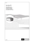
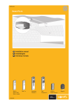
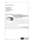
somfy.com
Elixo 500 24 V
EN Installation manual
ES Manual de instalación
PT Manual de instalação
EL Εγχειρίδιο εγκατάστασης
5054405A
Elixo 500 24 V
GENERAL INFORMATION
2
SAFETY
2
General information
Safety instructions
Motorising an existing gate
2
2
3
PRODUCT DESCRIPTION
3
Composition of the kit
Description of the motorisation
General motor size
Area of application
General view of a standard installation
INSTALLATION
3
3
3
4
4
4
Assembling the release lever
Disengaging the motorisation
Installing the motorisation
Wiring
4
4
5
6
QUICK COMMISSIONING
7
Installer interface
Language selection
Memorising remote controls
Self-learning
7
7
8
8
MOTORISATION OPERATION
9
CONNECTING ADDITIONAL PERIPHERALS
9
24 V integrated flashing amber light
Photoelectric cells
Reflex photoelectric cell
Wired keypad
Wired keyswitch
9
9
10
10
10
PARAMETER SETTING
11
CLEARING REMOTE CONTROLS AND SETTINGS
12
Clearing all remote controls
Clearing all motorisation settings
DIAGNOSTICS
Meaning of messages displayed on the screen
Display of the motor torque values during operation of the motorisation
TECHNICAL SPECIFICATIONS
Copyright © 2008 Somfy SAS. All rights reserved.
EN
CONTENTS
12
12
12
12
13
13
1
Elixo 500 24 V
GENERAL INFORMATION
EN
This product, installed in accordance with this guide, complies with EN 12453 and EN 13241-1 standards.
Somfy hereby declares that this product complies with the essential requirements and other relevant provisions of
Directive 1999/5/EC. A Declaration of Conformity is available at the web address www.somfy.com/ce (Elixo 500 24 V).
Suitable for use in EU, CH and NO.
SAFETY
General information
Always read this installation manual and the safety instructions before installing this Somfy product.
This Somfy product must be installed by a professional motorisation installer, for whom these instructions are intended.
The use of any safety components not approved by Somfy remains the sole responsibility of the installer.
These instructions describe how to install, commission and operate this product.
Moreover, the installer must comply with current standards and legislation in the country in which the product is being
installed, and inform his customers of the conditions for use and maintenance for the product.
Any usage outside of applications defined by Somfy constitutes non-compliance, and is therefore not covered by
the guarantee. In this event, as for all usage not consistent with the instructions given herein, Somfy accepts no
responsibility for harm or damage.
Safety instructions
Before installation, ensure that the gate frame conforms to current standards, particularly:
• The gate sliding rail must be straight and horizontal and the wheels must be able to support the weight of the gate.
• The gate should move easily over its entire travel distance and there should be no sign of excessive side sway.
• The upper guide should allow the gate exact clearance to ensure regular, silent movement.
• End stops must be installed on the ground at both the opening and closing stop positions.
• The position in which the motorisation mechanism will be fitted must allow for safe and easy manual release.
If after evaluation the gate system does not meet the conditions set out above, it must be repaired or, if necessary,
replaced.
The selected safety accessories for the installation must comply with the current standards and regulations in force in the
country in which the product is being installed.
Ensure that there are no danger zones (risk of crushing, cutting, trapping), between the gate and the surrounding fixed
elements, caused by the opening movement of the gate.
On a barred gate, if the bars are more than 40 mm apart, install an appropriate safety device to prevent cutting.
Maintain a clear area of 500 mm behind the gate when it is completely open.
Take care while the gate is moving.
Place the fixed control devices and remote controls out of the reach of children.
Any switch without a locking device must be installed in direct view of the gate and away from any mobile parts. The
minimum height at which it must be installed is 1.5 m. It must not be accessible to the public.
During installation of the motorisation:
• Remove any jewellery (bracelets, chains, etc.).
• For drilling and welding operations, wear special glasses and sufficient protection.
• Use the appropriate tools.
• Do not connect to the mains or to a backup battery before installation is complete.
• Be careful when handling the motorisation system to prevent any risk of injury.
In order to operate, the motorisation must be supplied with 230 V 50 Hz. The electric supply should:
• solely be used for the motorisation,
• have a minimum cross section of 1.5 mm²,
• be fitted with an approved all-pole switch with contact openings of at least 3.5 mm, fitted with a protection device
(fuse or circuit breaker with a 16 A rating) and a differential device (30 mA),
• be installed in accordance with the current electrical safety standards.
It is recommended that the installation be fitted with a lightning conductor (in compliance with standard NF C 61740,
maximum residual voltage 2 kV).
When installation is complete, ensure that the mechanism is correctly set and that the gate changes direction when it
encounters an obstacle.
2
Copyright © 2008 Somfy SAS. All rights reserved.
Elixo 500 24 V
Regularly check the condition of the gate. Gates in poor condition must be repaired, reinforced or even replaced. Check
that the various motorisation component’s screws and fittings are correctly tightened.
EN
Before carrying out any work on the installation, switch off the power supply and/or disconnect any backup batteries.
Motorising an existing gate
Carry out a stress test with a measuring device which conforms to the requirements set out on in clause 5.1.1 of
standard EN 12445.
PRODUCT DESCRIPTION
Contents of the standard kit
1
Elixo 24 V Motor
x1
2
Keytis 2 RTS remote control
x2
3
RTS 3 m offset aerial
x1
1
4a
4b
Ground mounting kit:
4a
Lag screws
x4
4b
Nut
x8
4c
Washer
x4
4d
Plug
x4
4e
2
Base plate
3
4c
4d
4e
x1
5
Manual release handle assembly
x1
6
Handle locking key
x2
7
End limit brackets
x2
6 5
Description of the motorisation
1
Motor
2
Reduction unit with worm screws - helicoid drive wheel
3
Electro-mechanical end limit unit
4
Pinion
5
Manual release mechanism
6
Control unit
7
7a
7b
1
3
6
7c
Battery pack (optional, ref. 9014612):
7a
2 backup batteries
7b
Battery holder tray
7c
Battery power supply management card
2
4
5
56
37
Øp
260
General motor size
50
122
22
43
9
15
96
131
227
Copyright © 2008 Somfy SAS. All rights reserved.
3
Elixo 500 24 V
Area of application
Sliding gates up to 500 kg and carrying out 30 operations per day.
EN
To ensure the safety of all equipment and persons, respect the information given in the table:
For a gate weighing ...
0 to 300 kg
use ...
a passive rubber profile
on the end of the gate
Ref.
9014597
300 to 500 kg
a passive rubber profile
on the end of the gate
9014598
If using a different rubber profile to those listed above, ensure that the installation conforms with current regulations.
General view of a standard installation
A
Motor
B
Rack
C
Aerial
D
Amber light
E
Set of photoelectric cells
F
Keyswitch
G
Passive rubber profile
H
End limit brackets
i
End stops in the ground
D
C
C
i
A
D
E
B
E
G
F
G
E F
H
E
i
INSTALLATION
The motorisation must be disengaged during installation.
Assembling the manual release handle
[1] Insert the release handle into the specific housing on the motor.
[2] Tighten the release handle.
[3] Fit the screw cover.
Disengaging the motorisation
[1] Turn the key a quarter of a turn to the left.
[2] Turn the release handle to the right.
Do not forcibly push the gate. Hold the gate over its entire travel
during manual manoeuvres.
4
Copyright © 2008 Somfy SAS. All rights reserved.
Elixo 500 24 V
Installing the motorisation
The motor mounting kit provided is to be used on a concrete
base. For all other types of mounting, use the appropriate
fittings.
EN
Fitting the mounting system
14 mm
[1] Position the base plate:
• parallel to the gate,
• with the symbol of the pinion pointing towards the gate,
• by moving it by 25 mm in relation to the front line of the
rack (if the rack is fitted with a cover, measure from the
line on the rack, not on the cover),
• so that it does not obstruct movement and to ensure the
gate is able to open and close completely.
m
m
25
[2] Mark the location for the ground mountings.
[3] Drill to a depth of 85mm.
[4] Insert the plugs.
[5] Tighten the lag screws on:
60 mm
• the threaded section for a rack height of between 110 and
130 mm,
100 mm<h<110 mm
• the threaded section + the unthreaded section for a rack
height of between 100 and 110 mm.
20 mm
110 mm<h<130 mm
55 mm
77
To facilitate tightening of the lag screws, use 2
nuts to form a “double nut”.
>23
h
[6] Screw a nut onto each lag screw.
100
h 130
85
[7] Place the base plate onto the lag screws with the symbol of
the pinion pointing towards the gate. It must be a minimum
of 23 mm from the ground.
25
Mounting the motor
[1] Position the motor on the lag screws, insert it and push it
towards the gate.
[2] Ensure the pinion is correctly positioned under the rack.
[3] Set the height of the motor and/or the rack to ensure a
clearance of approximately 2 mm between the rack and the
pinion. This setting is important to prevent premature wear
of the pinion and rack; the pinion must not be supporting
the weight of the gate.
NO
OK
[4] Check that:
• the motor is level,
• the gate runs correctly,
2 mm
• the setting nuts all come into contact with the base of the
motor,
• the clearance between the rack and pinion does not vary
significantly over the gate’s travel.
50
[5] Fit a washer and nut onto each lag screw in order to fit the
motor.
>23
h
100
h 130
25
Copyright © 2008 Somfy SAS. All rights reserved.
5
Elixo 500 24 V
Fitting the end limit brackets
SX
[1] Manually move the gate to the open position.
DX
[2] Position a bracket onto the rack so that it activates the motor end limit contact.
EN
[3] Screw the bracket onto the rack.
[4] Manually move the gate to the closed position then repeat steps 2 and 3 to fit
the second bracket to the rack.
Wiring
General wiring diagram
Terminals
1-2
3-4
5
6
7
8-9
10
11
12-13
14-15
16-17
18
19
20
21
22
23
24
25
26
31-32
33
34
Description
A-B
0V-24V~
COM
SWC
SWO
ANT
ANT
24 V~/--SCA
24 V~/--- (V Safe)
FAULT
COM
PED
COM
START/CLOSE
STOP
PHOT
BAR
OPEN
N
L
Function
Motor connection
Secondary transformer
Shared by end limit contacts
Closing end limit contact
Opening end limit contact
24 V output, flashing orange light
Aerial core
Aerial braid
Alternating 24 V output for power supply to the additional devices
Gate status indicator output (open/closed)
Alternative 24 V output for power supply to, and autotest of, safety devices
Input for safety devices autotest
Shared by control inputs (18-20)
Pedestrian opening control point input
Shared by control inputs (22-23-24-25-26)
Sequential operation control point input (adjustable in the LoGic menu, see pg.11)
Control point input (closing only)
Photoelectric cell input
Safety edge sensor input
Opening control point only
Primary transformer 230 V~
Neutral single-phase 230 V~, 50-60 Hz power supply
Live single-phase 230 V~, 50-60 Hz power supply
Aerial wiring
For optimum reception, the aerial must not be cut
and must be as far away as possible from the power
supply terminal blocks and wires. The aerial must
always be installed at a height and must be visible
from a distance.
Do not fit the aerial to a metal post or behind a wire
fence.
Cut the coaxial cable if it is too long. Shortening the
cable will improve the signal (a coaxial wire which is
too long, extended or connected with an insulating
screw joint will distort the signal).
b
a
11
a
b
10
5 mm
15 mm
P2
The mounting plate is an active component of the
aerial. It must not be removed or modified.
6
Copyright © 2008 Somfy SAS. All rights reserved.
Elixo 500 24 V
Connection to the power supply
To connect the motor to the power supply, use a standard, multicore cable with a minimum
cross section of 3x1.5 mm².
N
L
33
34
EN
Inputs 23, 24 and 25 must be bridged to terminal 21 if they are not used to
connect a safety device.
P1
Checking the motorisation wiring
Motor connection
End limit connection
Wire
Red
Blue
Brown
Red
Black
Motorisation to the left (A)
Terminal
1
2
6
7
5
Motorisation to the right (B)
Terminal
2
1
7
6
5
A
B
Switch on the power to the installation before commissioning.
QUICK COMMISSIONING
Installer interface
Parameter setting is carried out using the buttons on the control unit
Press ...
to...
OK
enter the menu and sub-menu
PROG
confirm a parameter setting
+ OR -
select parameters
modify a parameter value
+ AND -
exit the active menu
(press simultaneously)
Language selection
[1] Press the OK button. Information is displayed on the screen (information
details - pg. 12).
OK
OK
- +
[2] Press the OK button.
[3] Use the + and - buttons on the control unit to access the "LAnGUE" (Language)
menu.
[4] Press the OK button.
[5] Use the + and - buttons to access the required language.
[6] Press the OK button to confirm your selection.
Copyright © 2008 Somfy SAS. All rights reserved.
OK
+-
OK
- +
OK
- +
OK
- +
OK
- +
OK
7
Elixo 500 24 V
Memorising the remote controls
To memorise a remote control:
.......2 min........
EN
[1] Press the PROG button on the control unit for 2
seconds. The red indicator light will come on.
2s
[2] Press a channel on the remote control to which the
motorisation will be linked within 2 minutes. The
red indicator light flashes, the remote control has
been memorised.
If this procedure is carried out using a channel which
has already been memorised, this channel will be
cleared.
[1]
[2]
To add other remote controls: repeat the above
procedure.
.......2 min........
To add a Telis type remote control:
[1] Press the PROG button on the control unit for 2
seconds. The red indicator light will come on.
[2] Press the PROG button on the back of the Telis.
This must be done within 2 minutes. The red
indicator light flashes, the remote control has been
memorised
2s
[1]
[2]
To exit programming mode without memorising a
remote control: briefly press the PROG button on the
control unit.
Self-learning
The gate’s travel self-learning is essential when commissioning the motorisation.
During self-learning, the obstacle detection function is not active. Remove any objects or obstacles and do not
allow any persons near or inside the operating range of the motorisation.
To carry out an emergency stop during self-learning, use a memorised remote control.
Before beginning self-learning
Ensure the rail is clean.
Manually move the gate to the closed position.
Re-engage the motorisation:
[1]
[1] Turn the release handle to the left.
[2] Move the gate manually until the drive mechanism re-locks.
[3] Turn the key a quarter of a turn to the right.
SuC (closing end limit activated) should be displayed on the motorisation screen.
If SuO (opening end limit activated) is displayed, check the
motorisation wiring (see pg. 7).
[2]
Start self-learning
OK
Self-learning comprises 2 cycles (1 cycle = 1 opening + 1 closing):
• The 1st cycle is carried out without slowing down and enables the
motor to memorise the gate’s entire travel.
OK
• The 2nd cycle includes slowing down in order to establish the
minimum torque value needed for movement of the gate.
- +
[1] Press the OK button on the control unit twice to access the menus.
[2] Use the + and - buttons on the control unit to access the AutoSet
menu.
OK
OK
OK
+-
[3] Press the OK button to confirm. Self-learning has started. The gate
must complete 2 full cycles.
8
Copyright © 2008 Somfy SAS. All rights reserved.
Elixo 500 24 V
If self-learning is correct, OK is displayed on the motorisation screen.
If self-learning has failed, KO is displayed on the motorisation screen. Check the following before restarting self-learning:
• the gate runs correctly,
EN
• there is nothing obstructing the photoelectric cells (if fitted).
If self-learning is interrupted, return the gate to the closed position and restart self-learning.
If the slowing down speed is subsequently changed, self-learning must be carried out again.
AT THIS STAGE IN THE INSTALLATION, THE MOTORISATION IS OPERATIONAL.
MOTORISATION OPERATION
See pages 2 and 3 in the user’s manual.
CONNECTING ADDITIONAL DEVICES
24 V integrated flashing amber light
(ref. 9 014 552)
Photoelectric cells
With autotest
24V
ac/dc 0V
1
2
Without autotest
24V
ac/dc 0V
24V
ac/dc 0V C NC NO
1
2
3
4
1
5
CE
CR
Activate the cell autotest function: tESt Phot to ON in the LoGIc
menu.
Copyright © 2008 Somfy SAS. All rights reserved.
CE
2
24V
ac/dc 0V C NC NO
1
2
3
4
5
CR
Deactivate the cell autotest function: tESt Phot to OFF in the LoGIc
menu.
9
Elixo 500 24 V
Reflex photoelectric cell
Without autotest
EN
With autotest
8
7
6
5
4
3
2
1
9 10 11 12 13 14
Ref. 9014896
Activate the cell autotest function: tESt Phot to ON in the LoGIc
menu.
On the cell, set the DIP switch1 to ON and the DIP switch2 to OFF.
Deactivate the cell autotest function: tESt Phot to OFF in the
LoGIc menu.
On the cell, set the DIP switch1 and the DIP switch2 to ON.
Wired keypad
7s
–
+
H
H P2 M P1 T3 C3 R3 T2 C2 R2 T1 C1 R1 V
V
}
}
E
Wired keyswitch
A
B
10
7s
A
B
Copyright © 2008 Somfy SAS. All rights reserved.
Elixo 500 24 V
PARAMETER SETTING
Menu [Display]
Value
By
default
EN
If the parameters are changed after self-learning has been carried out, ensure the installation conforms to all
relevant standards.
Comments
Language [LAnGUAGE]: to select the language for displaying information on the control unit screen.
French [Fra]
English [Eng]
Spanish [Esp]
German [Deu]
Italian [Ita]
Fra
Self-learning [AutoSet]: to start self-learning for the gate travel.
Parameters [PArAM]: to change the torque, speed and slowing down values for the motorisation.
Automatic closure time
[tcA]
Opening motor torque
[oP. t]
Closing motor torque
[cLS.t]
Opening motor torque
while slowing down
[oP. t Slow]
Closing motor torque
while slowing down
[cLS. t SLow]
Normal opening speed
time [norM. oP. SPEED]
Normal closing speed
time [norM. cLS. SPEED]
Between 3 and 120 seconds
10 s
Between 1% and 99%
80%
Between 1% and 99%
50%
Between 1% and 99%
50%
Between 1% and 99%
50%
Between 1 second and 2
minutes
Between 1 second and 2
minutes
15 s
Slowing down speed
[SLow SPEED]
0 - No slowing down
1 - Slowing level 1 (1/2)
2 - Slowing level 2 (1/3)
3 - Slowing level 3 (1/4)
3
15 s
Setting the time delay for automatic reclosing (If tcA is activated in
LoGic)
The setting for the minimum motor torque value needed to move the
gate is carried out during auto-programming.
Refer to the paragraph entitled “Display of the motor torque values
during operation of the motorisation” pg. 13 to set the motor torque
values.
The slowing down time during opening and closing can be set by
changing the “normal speed time”; the higher the normal speed
travel, the shorter the slowing down time.
E.g.: if the duration of an opening manoeuvre is 15 seconds, for a
slowing down time of 3 seconds, the “normal speed time” must be set
to 12 seconds.
0 - Normal speed
1 - Average speed
2 - Slow speed
3 - Very slow speed
Logic [LoGIc]: to select the motor operating mode and devices.
Automatic closure [tcA]
3 Step
[3 STEP]
Blocking impulses
[IbL oPEn]
Photoelectric cell
operation
[Photoc. oPEn]
Photoelectric cell test
[tESt Phot]
Gate open indicator
[ScA 2ch]
Pre-warning
[PrEAL]
ON: Activates automatic
closure
OFF: Deactivates automatic
closure
ON: Activates the 3 step logic.
OFF: Activates the 4 step logic.
ON: In opening mode only
OFF: None
ON: In closing mode only.
OFF
The gate closes automatically after the programmed time delay.
OFF
3 STEP = operation in semi-automatic mode (see “User's manual” pg. 3).
4 STEP = operation in sequential mode (see “User's manual” pg. 3).
Impulses during opening have no effect.
OFF
OFF
OFF: In opening and closing
mode.
ON: Activates the cell autotest
function.
OFF: Deactivates the cell
autotest function.
ON: The output between
terminals 14 and 15 has been
configured as the gate open
indicator.
ON: With pre-warning
OFF
OFF
OFF: Without pre-warning
Sustained action
[hoLd-to-rUn]
ON: Operation with sustained
action activated.
OFF: Operation with
impulse action, according to
3 or 4 step logic.
Copyright © 2008 Somfy SAS. All rights reserved.
OFF
In closing mode, the gate stops then reverses its movement.
In opening mode, cells are inactive.
In closing mode, the gate stops and reverses its movement once
the cells are no longer obstructed.
In opening mode, the gate stops then continues its movement
once the cells are no longer obstructed.
See the diagram for connection of the cells with autotest pg. 9 and 10.
With pre-warning: the integrated flashing amber light comes on
approximately 3 seconds before motorisation starts.
Without pre-warning: the integrated flashing amber light comes
on when motorisation starts.
Operation in hold-to-run mode, only with a wired control: continuous
movement while the control button remains pressed.
11
Elixo 500 24 V
Menu [Display]
EN
START-CLOSE selection
[StArt - cLoSE]
Pedestrian opening
[PEdEStrIAn]
Value
By
default
Comments
ON: the input between
terminals 21 and 22 operates
as CLOSE.
OFF: the input between
terminals 21 and 22
operates as START.
ON: Activates the pedestrian
opening.
OFF: Deactivates the
pedestrian opening.
OFF
CLOSE: the device connected between terminals 21 and 22 only
enables the gate to be closed.
START: the device connected between terminals 21 and 22
enables the motorisation to operate in sequential mode.
OFF
Operation of the pedestrian opening: pressing the button briefly
opens the gate partially and pressing and holding the button opens
the gate fully.
Fixed opening time: 7 seconds.
Preset [dEFAULt]: to reset the motor (factory default settings).
CLEARING THE REMOTE CONTROLS AND ALL SETTINGS
Clearing all remote controls
Press the PROG button on the motorisation control unit for more than 7 seconds. The indicator light flashes to indicate that all
remote controls have been cleared.
OK
Clearing all settings
OK
[1] Press OK twice to access the menus.
[2] Use the + and - buttons to access the dEFAULt menu.
[3] Press OK to clear all settings.
- +
The Elixo motorisation has been reset and returns to its original configuration (factory default
settings).
OK
OK
+-
Before using the motorisation, carry out a new self-learning procedure (see pg. 8).
DIAGNOSTICS
Meaning of messages displayed on the screen
Before accessing the menu list, the control unit screen displays the following information:
• Somfy,
• Control unit software version,
• Number of cycles carried out (expressed in hundreds; during the first 100 manoeuvres the screen displays 0000).
Whilst the motorisation is in use, messages are displayed to show the system’s status.
In the event of incorrect operation, a message will be permanently displayed to show the device to be checked. If the problem is
not corrected or if it persists, please contact Somfy technical assistance.
12
Message
OK
KO
Meaning
Self-learning successful
Self-learning unsuccessful
Awaiting input of a value or function
End
SuC
SuO
AMP
PED
Exit programming mode
Closing end limit activated
Opening end limit activated
Obstacle detected
Pedestrian entry activated
STRT
STOP
PHOT
START entry activated
STOP entry activated
PHOT entry activated
CLOSE
OPEN
SWO
SWC
TH
CLOSE entry activated
OPEN entry activated
Opening end limit entry activated
Closing end limit entry activated
Software thermal protection activated
Permanent display
Check that the device controlling pedestrian entry is operating correctly (keyswitch,
wired keypad, etc.)
Check that the device controlling the START entry is operating correctly.
Check that the device controlling the STOP entry is operating correctly.
Check that nothing is obstructing the photoelectric cells.
Check that the photoelectric cells are not dirty (see guide for the cells).
Check that the device controlling the CLOSE entry is operating correctly.
Check that the device controlling the OPEN entry is operating correctly.
Faulty electro-magnetic detection system. Replace it.
Faulty electromagnetic detection system. Replace it.
Wait until the message disappears before continuing to use the motorisation.
Copyright © 2008 Somfy SAS. All rights reserved.
Elixo 500 24 V
During the opening and closing phases, four figures separated by a dot are displayed on the screen, for example 35.40. The
figures are updated whilst the gate is moving. They represent the actual torque used (35) and the torque set during the selflearning procedure (40).
These values enable the torque entry to be corrected.
If the value of the actual torque used during movement of the gate more or less approaches the value of the programmed torque,
operating faults may occur in the future, due to wear or slight warping of the gate.
If the value of the actual torque used exceeds the value of the programmed torque, the gate will stop and reverse by several
centimetres.
TECHNICAL SPECIFICATIONS
MOTOR
Power supply
Motor power supply
Motor revolutions
Power consumption
Maximum consumed current
Reduction ratio
Revolutions at output
Pinion
Gate speed
Maximum weight of the gate
Maximum torque
Lubrication
Manual manoeuvres
Obstacle detection
Number of cycles/day
Control unit
Backup batteries (optional)
Operating temperature
Index protection rating
Weight
Dimensions
230 V 50/60 Hz
24 Vdc
3500 rpm
70 W
0.5 A (23 Vac) - 1 A (110 Vac)
1/44
79 rpm
4 mm module (14 teeth)
12 m/min
500 kg
20 Nm
Permanent grease
Mechanical release with handle
Electronic torque limiter
30
Built in with LCD display
Two 12 V 1.2 Ah batteries
-20 °C to +60 °C
IP24
7 kg (~ 70 N)
see “General motor size” pg.3
ELECTRONICS
Accessories power supply
Automatic closure time
Operating time
Pedestrian opening time
Reversal pause
Integrated flashing amber light connection
Fuses
Built in radio receiver
Number of memorizable remote controls
RTS remote control frequency
Aerial resistance
Copyright © 2008 Somfy SAS. All rights reserved.
24 Vac (180 mA)
between 3 and 120 seconds
120 s
7 seconds (fixed)
1 second approximately
24 V maximum 25 W
250 V T 0.62 A and T 1 A
RTS
36
433.42 Mhz
50 Ohm (RG58)
13
EN
Display of the motor torque values during operation of the motorisation
EN
Elixo 500 24 V
14
Copyright © 2008 Somfy SAS. All rights reserved.