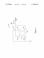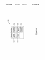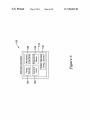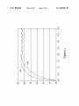
1
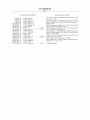
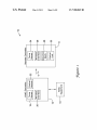
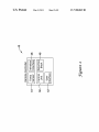
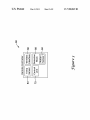
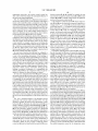
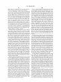
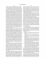
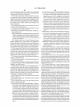
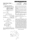
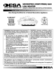
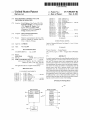
US007900849B2
(12) Ulllted States Patent
(10) Patent N0.:
Barton et al.
(45) Date of Patent:
(54)
HVAC REMOTE CONTROL UNIT AND
METHODS OF OPERATION
(75)
Inventors: Eric J. Barton, Eden Pra1r1e,
(US);
Kenneth B. Kidder, Coon Rap1ds, MN
(US); Timothy M. Tinsley, Coon
.
5,590,831 A
5,603,451 A
5,654,813 A
. .
Rapids MN
-
’
5,803,915 A
5,833,134 A
5,339,654 A
6,152,375 A
John s_ Fultz
-
’
.
’
1/1997 Manson et a1.
2/1997 Helander et al.
8/1997 WhitWorth
*
.. 600/549
2/2002 Jones et al. ................ .. 340/10.1
6,679,830 B2*
6,810,307 B1
Subject to any disclaimer, the term of this
patent is extended or adjusted under 35
Natale et al.
5/2002 Morgan
10/2002
Sumida et a1.
1/2004 Kolarovic et al. ............ .. 600/22
10/2004 Addy
3/2006
Keller ......................... .. 340/581
(Continued)
U.S.C. 154(b) by 570 days.
OTHER PUBLICATIONS
APPI' NO‘: 11/948 966
Logitech, “Harmony 880 Remote User Manual,” v. 1, pp. 1-15, prior
’
(22) Filed:
et al.
3/2001 Dushane et a1.
7,012,535 B2 *
(21)
g ky
7/2001
6,460,774 B2
( * ) Notice:
Kremenchu s
6,348,856 B1 *
6,394,359 B1
MorristoWn, NJ (US)
9/1998
ll/l998 HO et a1‘
ii/i99g Weber
11/2000 Robison
6,260,765 B1
Young, Rlch?eld, MN (Us)
Ass1gnee: Honeywell International Inc.,
Mar. 8, 2011
6,196,467 B1
Mmneapqhs’ MN ms)’ Gregory W‘
_
(73)
US 7,900,849 B2
to Nov. 30, 2007.
NOV. 30, 2007
(Continued)
(65)
Prior Publication Data
US 2009/0140059 A1
Jun' 4, 2009
Primary Examiner * George Nguyen
(74) Attorney, Agent, or Firm * Seager Tufte & Wickhem
LLC
(51)
Int. Cl.
G05D 23/00
(52)
US. Cl. ......................... .. 236/51; 165/11.2; 374/120
(58)
Field of Classi?cation Search .................. .. 236/51;
(2006.01)
(57)
ABSTRACT
A Comfort Control System for Controlling the Comfort level in
a building includes a comfort control unit and a remote con
165/11.2, 237; 700/276; 341/176; 340/825-69,
trol unit. The remote control unit communicates With the
340/82572, 870.17, 589, 501; 374/120,
374/129, 141
See application ?le for complete search history.
comfort control unit from a remote location. In one illustra
tive embodiment, the remote control unit includes a tempera
ture sensor for sensing an ambient air temperature near the
_
(56)
remote control unit, and a measure related to the sensed
References Clted
temperature may be communicated to the comfort control
unit. A detection block may be included in the remote control
U.S. PATENT DOCUMENTS
4,336,902 A
unit for detecting When the ambient air temperature sensed by
6/1982 Neal
the temperature sensor in the remote control unit is likely to
be in?uenced by a user or other undesirable condition. The
4,399,823 A *
8/1983
4,433,719 A
2/1984 Cherryetal.
Donnelly .................... .. 600/549
4,585,164 A
4/1986 Butkovich et a1.
4,969,508 A *
5,199,637 A *
11/1990
4/1993
5,272,477 A
12/1993 Tashimaet a1.
comfort control unit may take this into account When control
Tate etal. ................... .. 165/209
Adams ...................... .. 236/78R
ling the comfort control system of the building.
28 Claims, 8 Drawing Sheets
/10
HVAC Controller
_/_\
Temp
18
20
Remote Controller
Control _\
Sensor
Module
/_\ Wireless
Interface
22
3
5533 '~—24
lvnvléi'fiii A?e
Dian-28
12J
can?‘ ~40
HVAC
Equipment
US 7,900,849 B2
Page 2
US. PATENT DOCUMENTS
7,083,109
7,089,088
7,108,194
7,146,253
B2
B2
B1
B2
8/2006
8/2006
9/2006
12/2006
OTHER PUBLICATIONS
LuX Products Corporation, “9000RF Remote Instructions,” 2 pages,
prior to Nov. 30, 2007.
OESA Heating Products, “Wireless Hand-Held Remote Control Sets
Pouchak
Terry et al.
Hankins, II
Hoog et a1.
Models (C)GHRCB and (C)GHRCTB, Operating Instructions,” 4
2003/0034897 A1
2003/0034898 A1
2003/0103075 A1
2/2003 Shamoon et al.
2/2003 Shamoon et al.
6/2003 Rosselot
pages, May 2003.
OMRON Electronic Components, LLC, “Micro Tilt Sensor D6B,”
2003/0107552 A1*
6/2003
Lu ............................... .. 345/163
OMRON Electronic Componenets, LLC, “Micro Tilt Sensor D6B,”
2003/0230632 A1*
12/2003
Morris .......................... .. 236/47
Cat. No. B02WAD1, 2 pages, Jun. 2002.
2004/0193324
2005/0083168
2005/0270151
2006/0071086
9/2004
4/2005
12/2005
4/2006
Hoog et a1.
Breitenbach
Winick
Kates
Sharp Corporation, “GP1S036HEZ Phototransistor Output, Trans
missive Photointerrupter With Tilt Direction (4-Direction) Detect
ing,” pp. 1-11, Oct. 3, 2005.
Totaline, “P/N 374-0431 Thermostat Remote Control & Receiver,”
KautZ et al. ................. .. 702/130
Kolk ............................... .. 374/1
11 pages, prior to Nov. 30, 2007.
Trane, “Wireless Zone Sensor,” 4 pages, Feb. 2006.
A1
A1
A1
A1
2006/0074586 A1*
2006/0165149 A1*
4/2006
7/2006
2006/0186213
2007/0114293
2007/0114295
2009/0140059
8/2006 Carey et a1.
A1
A1
A1
A1*
Travis Industries, Inc., “Remote Fireplace Thermostat, Part No.
99300651,” pp. 1-6, Feb. 3, 2003.
5/2007 Gugenheim
5/2007 Jenkins
6/2009
Barton et al.
Cat. No. JB301-E3-01, 6 pages, Mar. 2005.
................. .. 236/51
* cited by examiner
US. Patent
Mar. 8, 2011
Sheet 1 of8
US 7,900,849 B2
3/
LUMP=OEHCU
QE . Lomcw
N/
CQEUB
062m
_obcu “ED
miHpmwv
US. Patent
Mar. 8, 2011
Sheet 3 of8
US 7,900,849 B2
m’ m! m!
mLU_HO.EDCMU Qo_E. >. L8o9m:c3w5 c6o5ru:m0w v“_uEo_3m
core: Lomc
2m38%
US. Patent
Mar. 8, 2011
59 0
Sheet 4 0f 8
US 7,900,849 B2
8
23w8. “
N@
US. Patent
Mar. 8, 2011
Sheet 7 of8
US 7,900,849 B2
o.¢m.mo.mm.~o.NmA0%m.o0.0
Nw
ow
mm
mm
vh
NM
US. Patent
Mar. 8, 2011
US 7,900,849 B2
Sheet 8 0f 8
EwSQW
cm00ow
//
ww
Nw
ow
mm
mm
NB
on
US 7,900,849 B2
1
2
HVAC REMOTE CONTROL UNIT AND
METHODS OF OPERATION
ambient temperature sensed by the temperature sensor, and
for causing the Wireless interface to Wirelessly communicate
the measure related to the ambient temperature sensed by the
temperature sensor to the comfort control system.
In some cases, When the detection block detects that the
ambient temperature sensed by the temperature sensor is
likely to be in?uenced by a user, the control unit may, for
example: cause the Wireless interface to Wirelessly commu
nicate the measure related to the ambient temperature sensed
by the temperature sensor to the comfort control system less
often; cause the Wireless interface to suspend Wirelessly com
municating the measure related to the ambient temperature
sensed by the temperature sensor to the comfort control sys
tem; cause the Wireless interface to Wirelessly communicat
ing a signal to the comfort control system that indicates that
the ambient temperature sensed by the temperature sensor is
likely to be in?uenced by a user; and/or cause any other
desired response, if any.
FIELD
The present invention relates generally to HVAC control
lers for controlling HVAC systems, and more particularly, to
HVAC controllers that include a portable remote control unit.
BACKGROUND
Heating, ventilation, and/or air conditioning (HVAC) sys
tems are often used to control the comfort level Within a
building or other structure. Many HVAC controllers include a
controller that activates and deactivates one or more HVAC
components of the HVAC system to affect and control one or
more environmental conditions Within the building. These
environmental conditions can include, but are not limited to,
temperature, humidity, and/ or ventilation. In many cases, the
controller of the HVAC controller may include, or have access
In some cases, the remote control unit may include a user
20
to, one or more sensors, and may use sensed parameters
provided by the one or more sensors to control the one or more
HVAC components to achieve one or more programmed or
set environmental conditions.
In some cases, the HVAC controller may include a thermo
stat that is mounted to a Wall or the like of the building. A
typical thermostat includes a local temperature sensor and/or
interface, and the detection block may detect that the ambient
temperature sensed by the temperature sensor is likely to be
in?uenced by the user When the user interacts With the user
interface. For example, the detection block may monitor one
or more buttons or the user interface for user interaction. In
25
another case, the detection block may include a motion sensor
other sensors, Which may be used to sense one or more envi
to detect motion of the remote control unit by the user. In
another case, the detection block may include an attitude
sensor to detect When the attitude of the remote control unit is
ronmental conditions of the inside space proximate to the
an unacceptable attitude. In another example, the detection
thermostat, and/or may have access to one or more remotely 30 block may include an outer housing temperature sensor ther
mounted sensors that are mounted to a Wall or the like in the
mally coupled to an outer housing of the remote control unit
building at a location remote from the thermostat. In these
to sense a temperature change in?uenced by the user.
installations, the sensors are typically mounted at or near the
Walls of the building, and at particular ?xed locations Within
the building. In many cases, the occupants of the building do
not occupy the space immediately adjacent to the sensors, and
therefore, the environmental conditions sensed by the sensors
BRIEF DESCRIPTION
35
The invention may be more completely understood in con
sideration of the folloWing detailed description of various
illustrative embodiments of the invention in connection With
may not accurately represent the actual environmental con
ditions at the location of the occupants. Also, to make a
desired change to the environmental condition in the building,
the accompanying draWings, in Which:
40
the occupant must often Walk over and physically interact
With the thermostat. In Zoned systems, the occupant may have
FIG. 1 is a block diagram of an illustrative HVAC control
system including an HVAC controller and a portable remote
control unit;
FIG. 2 is a block diagram of another illustrative a remote
to Walk to each Zone and interact With a controller in each
control unit;
Zone.
45
SUMMARY
The folloWing summary is provided to facilitate an under
standing of some of the innovative features unique to the
present invention and is not intended to be a full description.
50
A full appreciation of the invention can be gained by taking
the entire speci?cation, claims, draWings, and abstract as a
Whole.
The present invention relates generally to HVAC control
lers for controlling HVAC systems, and more particularly, to
HVAC controllers that include a portable remote control unit.
outer housing temperature sensor; and
55
is provided. The remote control unit may include a tempera
60
control unit, a Wireless interface for Wirelessly communicat
ing a measure related to the ambient temperature sensed by
The folloWing description should be read With reference to
the draWings Wherein like reference numerals indicate like
elements throughout the several vieWs. The detailed descrip
tion and draWings shoW several embodiments Which are
meant to be illustrative of the claimed invention.
FIG. 1 is a block diagram of an illustrative HVAC control
the temperature sensor to the comfort control system, and a
detection block for detecting When the ambient temperature
sensed by the temperature sensor is likely to be in?uenced by
FIGS. 7 and 8 are graphs of an illustrative temperature
response of the temperature sensors of FIG. 6.
DETAILED DESCRIPTION
In one illustrative embodiment, a remote control unit for use
With a comfort control system of a building or other structure
ture sensor for sensing an ambient temperature at the remote
FIG. 3 is a block diagram of an illustrative remote control
unit having a motion sensor;
FIG. 4 is a schematic diagram of an illustrative motion
sensor of the remote control unit of FIG. 3;
FIG. 5 is a block diagram of an illustrative remote control
unit having an attitude sensor;
FIG. 6 is a block diagram of another illustrative remote
control unit having an ambient temperature sensor and an
65
system 10. The HVAC control system 10 may sometimes be
a user. In some cases, the remote control unit may include a
referred to as a comfort control system. In the illustrative
control unit for producing the measure that is related to the
embodiment, HVAC control system 10 may include a heat
US 7,900,849 B2
3
4
ing, ventilation, and air conditioning (HVAC) controller 12,
handheld remote control unit that can easily be carried by an
occupant of the building or other structure. The remote con
trol unit 14 may be, in some cases, a portable remote sensing
HVAC equipment 16 having one or more HVAC system com
ponents, and a remote control unit 14. In the illustrative
module for sensing an environmental parameter and provid
embodiment, HVAC controller 12 may be operatively con
nected in any suitable manner to HVAC equipment 16. HVAC
ing a measure related to the sensed environmental parameter
to HVAC controller 12 via the Wireless interfaces 26 and 20.
equipment 16 may include one or more HVAC system com
ponents that can be activated to regulate one or more envi
In other cases, the remote control unit 14 may be a more
sophisticated device that includes a remote user interface
ronmental conditions such as temperature, humidity, ventila
tion, and/ or other air quality levels Within a building or other
structure. Example HVAC equipment 16 may include, but are
(RUI) that alloWs a user to vieW, display and/or change one or
more parameters or settings of the HVAC controller 12 and/or
remote control unit 14, as desired. In some illustrative
not limited to, cooling units (eg air conditioners), heating
units (eg boilers, furnaces, etc.), ?ltration units, dampers,
embodiments, remote control unit 14 may alloW a user to
valves, sensors, humidi?er/dehumidi?er units, and ventila
tion units (eg fans, bloWers, etc.). In some cases, HVAC
interact With the HVAC Controller 12 from locations remote
from the HVAC Controller 12 itself.
As illustrated, remote control unit 14 includes a tempera
ture sensor 24, a Wireless interface 26, a detection block 28,
controller 12 may be a thermostat, such as, for example, a Wall
mountable thermostat, but this is not required in all embodi
ments.
and a control unit 30. While a temperature sensor 24 is shoWn
In the illustrative embodiment of FIG. 1, the HVAC con
troller 12 may include a control module 22, a temperature
sensor 18, and a Wireless interface 20. Temperature sensor 18
may sense the temperature proximate to the HVAC controller
12. As illustrated, temperature sensor 18 may be included
With the HVAC controller 12, such as Within the housing of
in FIG. 1, it is contemplated that the remote control unit 14
may alternatively, or in addition, have one or more other types
20
ured to sense the ambient temperature of the environment in
the vicinity of the remote control unit 14. In some cases,
Wireless interface 26 may be con?gured to Wirelessly com
HVAC controller 12. HoWever, it is contemplated that tem
perature sensor 18 may be located remote from the HVAC
25
controller 12, but in communication thereWith.
Control module 22 of HVAC controller 12 may be con?g
ured to control the comfort level of at least a portion of the
building or structure by activating and/ or deactivating one or
more of the HVAC components of HVAC equipment 16. In
some cases, control module 22 may be con?gured to control
one or more HVAC functions, such as, for example, HVAC
ambient temperature sensed by temperature sensor 24 and, in
30
In the illustrative embodiment, Wireless interface 20 may
be con?gured to Wirelessly communicate With a Wireless
interface 26 of the remote control unit 14. For example, Wire
less interface 20 may be con?gured to communicate With
Wireless interface 26 of the remote control unit 14 to send
and/or receive one or more signals that correspond to, for
35
40
45
adjacent to the remote control unit 14, and the remote control
unit 14 may relay a measure related to the sensed temperature
to the HVAC controller 12. The control module 22 of the
50
55
the comfort level at the location of the remote control unit
Within the building or other structure.
In one illustrative embodiment, the remote control unit 14
may be con?gured to be portable and thus held by a user from
time to time. This can result in the temperature sensor 24
registering an elevated sensed temperature caused by, for
In some cases, Wireless interface 20 of the HVAC control
ler 12 may also be con?gured to Wirelessly communicate (e.g.
transmit and/or receive signals) With one or more HVAC
60
ler 12 and one or more HVAC components of HVAC equip
ment 16, as desired.
In some cases, the remote control unit 14 may be a portable
HVAC controller 12 may use the measure related to the tem
perature sensed by the remote control unit 14 to help control
example, temperature sensor 24.
As indicated above, the remote control unit 14 may be
operatively connected to the HVAC controller 12 to provide
remote temperature sensing for the HVAC control system 10.
in the residential building. The temperature sensor 24 of the
remote control unit 14 may sense an ambient temperature
face, and/or any other suitable Wireless interface, as desired.
Wireless interface 20 may be in communication With the
control module 22 of the HVAC controller 12 to provide
components of HVAC equipment 16. In other cases, a hard
Wired interface may be provided betWeen the HVAC control
temperature (and/or other parameter) sensed at the ?xed loca
tion of the HVAC Controller 12 and/or at ?xed locations of
For example, in a residential home or building, the remote
control unit 14 may be carried betWeen a living room, a
kitchen, a den, a bedroom, and/or any other room or location
24 of the remote control unit 14. In the illustrative embodi
ment, the Wireless interface 20 may include, for example, a
information corresponding to the temperature sensed by, for
12.
During use, the remote control unit 14 may be carried to
various rooms or locations Within the building or structure by
the user to control the comfort level using the temperature
(and/ or other parameter) sensed at the current location of the
remote control unit 14, instead of or in addition to using the
remote Wall mounted sensors.
example, the temperature sensed by the temperature sensor
radio frequency (RF) Wireless interface, an infrared Wireless
interface, a microWave Wireless interface, an optical inter
some cases, may cause Wireless interface 26 to Wirelessly
communicate the measure related to the ambient temperature
sensed by the temperature sensor 24 to the HVAC controller
lation, trend logs, timers, environment sensing, and/or other
temperature sensed by temperature sensor 18 or a tempera
ture sensed by a temperature sensor 24 of the remote control
unit 14, as Will be discussed in further detail beloW.
municate (e.g. transmit and/or receive) With the Wireless
interface 20 of the HVAC controller 12. In the illustrative
embodiment, control unit 30 of the remote control unit 14
may be con?gured to produce a measure that is related to the
schedules, temperature setpoints, humidity setpoints, venti
HVAC functions, as desired. In the illustrative embodiment,
control module 22 may selectively control the comfort level
of at least a portion of the building or structure using the
of sensors (e.g. humidity sensors, gas sensors, etc.). As brie?y
mentioned previously, temperature sensor 24 may be con?g
example, heat transfer from the user’s hand to the remote
control unit 14. Likewise, remote control unit 14 may be
placed at locations Where the sensed temperature may not
accurately re?ect the ambient temperature of the room. For
example, the remote control unit 14 may not register an accu
rate temperature When the remote control unit 14 is placed in
bright sunlight, near an open WindoW or door, near a heat
65
source, or placed at another location Where the conditions
cause the sensed temperature to be inaccurate. Likewise, the
remote control unit 14 may be moved by the user to a location
US 7,900,849 B2
5
6
outside of the building or structure. In these and other situa
not meant to be limiting in any manner. It is to be understood
that the HVAC controller 12 and the remote control unit 14
may take on any suitable form, as desired.
In some cases, it is contemplated that the HVAC controller
tions, the HVAC system 10 may operate using an inaccurate
temperature reading, and may cause the HVAC system 10 to
consume excess energy and/or may cause at least a portion of
the building or structure to have relatively extreme high or
loW temperatures. Similar situations can arise for parameters
such as humidity, particularly When the remote control unit 14
includes a sensor for sensing such parameters.
In the illustrative embodiment of FIG. 1, detection block 28
12 may include a user interface that may alloW a user to
program and/or modify one or more control parameters of
remote control unit 12 and/or HVAC controller 12, such as
programming, setpoints and/or schedule parameters, as
desired. When so provided, the user interface may include a
touch screen, a liquid crystal display (LCD) panel and key
may be con?gured to detect When the ambient temperature
sensed by temperature sensor 24 of the remote control unit 14
is likely to be in?uenced by a user or other condition. For
pad, a dot matrix display, buttons and/or any other suitable
interface, as desired. LikeWise, remote control unit 14 may
example, detection block 28 may be con?gured to detect
When a user is likely holding the remote control unit 14, When
and/or modify one or more control parameters of remote
include a user interface that may alloW a user to program
a user is interacting With a user interface of the remote control
control unit 12 and/or HVAC controller 12, such as program
unit 14, When a user is moving the remote control unit 14,
When the remote control unit 14 has an unacceptable attitude,
When the remote control unit 14 has an unacceptable orien
tation, and/or When the remote control unit 14 might other
Wise be registering a temperature that is inaccurate. In some
cases, detection block 28 may be provided as part of the
control unit 30, control unit 30 may be provided as part of the
detector block 28, or control unit 30 and detection block 28
ming, setpoints and/or schedule parameters, as desired. In
may be provided separately, as desired.
In operation, and in one illustrative embodiment, When the
detection block 28 detects that the ambient temperature
sensed by the temperature sensor 24 is likely to be in?uenced
some embodiments, parameters of the HVAC controller 12
may be received via a user interface of remote control unit 14,
Which are then transmitted to the HVAC controller 12 via
20
25
a temperature sensor 44, a Wireless interface 46, a detection
block 48, and a control unit 50, similar to those described
above. The remote control unit 40 may also include a user
interface 42 that may alloW a user to program and/or modify
one or more control parameters of remote control unit 40
by a user or other condition, control unit 30 and/or detection
block 28 of the remote control unit 14 may, for example:
cause the Wireless interface 26 to Wirelessly communicate the
measure related to the ambient temperature sensed by tem
perature sensor 24 to the comfort control system (e. g. HVAC
controller 12 of FIG. 1) less often than When no such in?u
ence is detected; cause the Wireless interface 26 to suspend
Wirelessly communication of the measure related to the ambi
ent temperature sensed by the temperature sensor 24 to the
Wireless interface 26 and Wireless interface 20 for use by the
HVAC controller 12.
FIG. 2 is a block diagram of another illustrative a remote
control unit for use in a comfort control system. In the illus
trative embodiment of FIG. 2, remote control unit 40 includes
30
and/or HVAC controller 12, such as programming and/or
schedule parameters, as desired. In one illustrative embodi
ment, some or all of these parameters may be received via a
user interface 42 of remote control unit 40, and then trans
mitted to the HVAC controller (shoWn as 12 in FIG. 1) via
35
Wireless interface 46. In some cases, the user interface 42 may
include a touch screen, a liquid crystal display (LCD) panel
comfort control system (eg HVAC controller 12 of FIG. 1);
and keypad, a dot matrix display, one or more buttons and/or
cause the Wireless interface 26 to Wirelessly communicate a
any other suitable interface, as desired.
In the illustrative embodiment, detection block 48 may be
con?gured to monitor the user interface 42 for user interac
signal to the comfort control system (eg HVAC controller 12
of FIG. 1) that indicates that the ambient temperature sensed
by the temperature sensor 24 is likely to be in?uenced by a
40
user or other condition; and/or otherWise attempt to mitigate
tion. For example, detection block 48 may be con?gured to
monitor user interface 42 for keypad presses, button presses,
and/ or communicate the in?uence.
In some cases, the control unit 30 and/or detection block 28
touch screen touches, or any other user interaction, as desired.
When detection block 48 detects user interaction With remote
may sloW the ambient temperature response of the tempera
45
ture sensor 24 When an in?uence is detected. In the example
case of sloWing the temperature response, or suspending
Wireless communication betWeen Wireless interface 26 and
Wireless interface 20, the control module 22 of the HVAC
controller 12 may operate according to the last knoWn good
ambient temperature communicated by the remoter control
unit 14 or, in other cases, may operate using the temperature
sensed by temperature sensor 18 of the HVAC controller 12,
likely to be in?uenced by the user. In some cases, detection
block 48 may include softWare to monitor the user interface
42, but this is not required. Rather, it is contemplated that any
50
In some cases, When detection block 48 detects user inter
action Withuser interface 42, control unit 50 of remote control
unit 40 may be con?gured to sloW the reported temperature
55
sensed by the temperature sensor 24 is likely in?uenced by a
the sensed temperature changes for a period of time, reporting
60
an average or moving average of the sensed temperature
65
changes, or otherWise sloWing the temperature response that
is reported by the remote control unit 40. In other cases,
control unit 50 of the remote control unit 40 may temporarily
suspend reporting the sensed temperature to the comfort con
trol system, terminate Wireless communication With the com
temperature used by control module 22 When controlling the
comfort level of the space, as Will be discussed in further
detail beloW.
It should be recogniZed that HVAC controller 12 and
remote control unit 14 of FIG. 1 are merely illustrative and are
response to compensate for the heat added to the remote
control unit 40 by the user, such as, for example, by the user’ s
hand. The temperature response may be sloWed by, for
example, reporting temperature changes that are smaller than
user or other condition. This signal may include a compen
sation value that may be used to adjust the detected ambient
temperature, or may include an appropriate command for the
control module 22 of the HVAC controller 12 to adjust the
suitable manner of detecting user interaction With user inter
face 42 may be used, as desired.
as desired.
As discussed above, and in some cases, a signal may be
transmitted from the remote control unit 14 to the HVAC
controller 12 that indicates that the ambient temperature
control unit 40, detection block 48 may determine that the
ambient temperature sensed by the temperature sensor 44 is
fort control system requiring a user to manually restart com
munication, report the ambient temperature sensed by
US 7,900,849 B2
7
8
temperature sensor 44 to the comfort control system less
betWeen contacts 82, 84, 86, and 88. For example, the caps
often, and/ or otherwise mitigate the anticipated in?uence of
may extend at an angle from metal contacts 86 and 88 to metal
contacts 82 and 84 to coincide, at least in part, an angled rest
the user on the sensed temperature.
FIG. 3 is a block diagram of an illustrative remote control
position of the remote control unit 60.
In the illustrative roller ball sWitch 80 circuit, metal con
tacts 82 and 86 may be electrically connected in parallel to a
voltage source VDD. A resistor 92 may be provided in series
unit having a motion sensor. In the illustrative embodiment,
remote control unit 60 includes a temperature sensor 64, a
Wireless interface 66, a detection block 68, a control unit 70,
and a motion sensor 62. The motion sensor 62 is con?gured to
sense motion of the remote control unit 60. In some cases, the
motion sensor 62 may be a roller ball sWitch, an accelerom
eter, a gyroscope, or any other suitable motion sensor, as
With voltage sourceVDD. As illustrated, metal contacts 82 and
86 are electrically connected to VDD are separated by metal
contacts 84 and 88, Which are electrically connected to
ground. As illustrated, metal contacts 82, 84, 86, and 88 may
desired. As illustrated, motion sensor 62 may be provided as
part of detection block 68, but this is not required.
In the illustrative embodiment, detection block 68 may be
con?gured to detect that the ambient temperature sensed by
be spaced such that the metal ball 90 can not pass betWeen
the temperature sensor 64 is likely to be in?uenced by the user
When the motion sensor 62 detects motion of the remote
control unit 60. For example, When the user is holding the
remote control unit 60, Walking With the remote control unit
60, or otherWise moving remote control unit 60, motion sen
sor 62 may detect motion of the remote control unit 60.
Motion sensor 62 may be part of or coupled to detection block
68 and may indicate When there is motion.
In some cases, detection block 68 may be con?gured to
determine if a motion sensed by motion sensor 62 is caused by
contact tWo adjacent metal contacts 82, 84, 86, and 88 at a
time, but not three or more. In this arrangement, When metal
adjacent contacts 82, 84, 86, and 88. Also, metal contacts 82,
84, 86, and 88 may be spaced such that metal ball 90 may
20
the user, the metal ball 90 may roll around the chamber 94
25
structure. For example, detection block 68 may be con?gured
to include a ?lter to ?lter out high frequency vibrations sensed
by motion sensor 62. Example high frequency vibrations that
30
a completed circuit is not present. Using output 96, detection
block 68 may detect movement of the remote control unit 60
indicated by signal changes at output 96. For example, if
output 96 changes state, detection block may determine that
the remote control unit 60 is being moved.
quency of vibrations or other movements, as desired.
In some cases, When detection block 68 detects motion of
the remote controller 40 via motion sensor 62, control unit 70
may be con?gured to sloW the reported temperature response
to compensate for the anticipate heat added to the remote
control unit 60 by the user, such as, for example, by the user’ s
hand. In other cases, control unit 70 of the remote control unit
60 may temporarily suspend reporting the sensed temperature
to the comfort control system for a period of time, terminate
Wireless communication With the comfort control system
making and breaking contact With metal contacts 82, 84, 86,
and 88. An output 96 of the sWitch 80 may be coupled to the
detection block 68 to provide a signal corresponding to the
state of the sWitch 80. The output 96 may provide a ?rst signal
When a completed circuit is present and a second signal When
a user or the surrounding environment of the building or
may be ?ltered out may include, but is not limited to, high
frequency vibrations associated With an airplane ?ying over
the building or structure or high frequency vibrations associ
ated With a vehicle, such as semi-trucks, driving past the
building or structure. Furthermore, it is contemplated that
detection block 68 may be con?gured to ?lter out any fre
ball 90 contacts tWo adjacent metal contacts 82, 84, 86, and
88, the metal ball 90 may produce a complete circuit in the
roller ball sWitch 80. In other Words, metal ball 90 may
connect voltage source VDD to ground, thereby resulting in a
voltage drop across resistor 92.
In operation, When the remote control unit 60 is moved by
45
FIG. 5 is a block diagram of an illustrative remote control
unit 100 having an attitude sensor. In the illustrative embodi
ment shoWn, remote control unit 100 includes a temperature
sensor 104, a Wireless interface 106, a detection block 108, a
control unit 110 and an attitude sensor 102. The attitude
sensor 102 may be used to sense the attitude (e. g. orientation)
of the remote control unit 100. In some cases, the attitude
sensor 102 may be a tilt sensor, a pendulum sWitch, a base
sWitch, a spring actuated foot or button, an accelerometer, a
gyroscope, or any other suitable attitude sensor, as desired. As
illustrated, attitude sensor 102 may be provided as part of
detection block 108, but this is not required.
requiring a user to manually restart communication of the
sensed temperature, report the ambient temperature sensed
In some illustrative embodiments, detectionblock 108 may
by temperature sensor 64 to the comfort control system less
often, and/ or otherWise mitigate the anticipated in?uence of
be con?gured to detect that the ambient temperature sensed
by the temperature sensor 104 is likely to be in?uenced by the
the user on the sensed temperature of the remote control unit
60.
FIG. 4 is a schematic diagram of an illustrative motion
sensor 62 of the remote control unit 60 of FIG. 3. In the
illustrative example, the motion sensor 62 includes a roller
50
ball sWitch 80. As illustrated, the roller ball sWitch 80 may
include a plurality of metal contacts 82, 84, 86, and 88 sur
rounding a metal ball 90. The metal contacts 82, 84, 86, and
88 may be positioned to de?ne a perimeter of a chamber 94
for housing the metal ball 90. In the illustrative embodiment,
metal contacts 82, 84, 86, and 88 and metal ball 90 may
55
user When the attitude sensor 102 detects that the attitude of
the remote control unit 100 is unacceptable. In operation, and
in one illustrative embodiment, When the detection block 108
detects that the ambient temperature sensed by the tempera
include an electrically conductive materials such as metal.
ture sensor 104 is likely to be in?uenced by a user, control unit
110 and/or detection block 108 of the remote control unit 100
may, for example: cause the Wireless interface 106 to Wire
lessly communicate the measure related to the ambient tem
perature sensed by temperature sensor 104 to the comfort
control system (eg HVAC controller 12 of FIG. 1) less often
than When no such in?uence is detected; cause the Wireless
interface 106 to suspend Wirelessly communication of the
some cases, the one or more non-conductive caps may be 65
measure related to the ambient temperature sensed by the
temperature sensor 104 to the comfort control system (eg
HVAC controller 12 of FIG. 1); cause the Wireless interface
106 to Wirelessly communicate a signal to the comfort control
contoured to de?ne, in part, an angle at Which the remote
control unit 60 must be rotated before the metal ball 90 moves
system (eg HVAC controller 12 of FIG. 1) that indicates that
the ambient temperature sensed by the temperature sensor
In some cases, the chamber 94 may include one or more
non-conductive caps (not shoWn) de?ning a top surface of the
chamber 94 and/or a bottom surface of the chamber 94. In
US 7,900,849 B2
9
10
104 is likely to be in?uenced by a user; and/or otherwise
attempt to mitigate and/or communicate the in?uence.
In some embodiments, remote control unit 100 may
FIG. 6 is a block diagram of another illustrative remote
control unit 120. In the illustrative embodiment, remote con
trol unit 120 may include an ambient air temperature sensor
124, a Wireless interface 126, a detection block 128, a control
unit 130, and an outer housing temperature sensor 132. The
ambient air temperature sensor 124 of FIG. 6 may be similar
to the temperature sensors 24, 44, 64, and 104 discussed
include an alert to alert the user When the detection block 108
detects that the ambient temperature sensed by the tempera
ture sensor 104 is likely to be in?uenced by the user, and/or
When the comfort control system (e. g. HVAC controller 12 of
above, Which may also be considered ambient air temperature
sensors. In the illustrative embodiment, the outer housing
FIG. 1) is no longer controlling based upon the temperature
sensed at the remote control unit 100. In some cases, the alert
temperature sensor 132 may be more thermally coupled to an
outer housing 122 of the remote control unit 120 than the
may alert the user that the remote control unit 100 is posi
tioned in an unacceptable attitude. In some cases, the alert
may be an audible alert, such as a beep or siren, or could be a
?ashing alert, such as a ?ashing background on a display or
other visual indicator. These are just some example alerts, but
it is contemplated that any other suitable alert may be used, if
such an alert is desired. Furthermore, it is contemplated that
an alert may be incorporated into any suitable embodiment
disclosed herein alerting the user of user in?uence or unac
ceptable orientation or attitude, as desired.
When the attitude sensor 102 includes a sWitch, either the
base sWitch or spring actuated foot or button, the attitude
20
from a user more quickly than ambient temperature sensor
124. In some cases, outer housing temperature sensor 132
sensor 102 may include a sWitch at the base of the remote
control unit 100 con?gured to enable comfort control using
the temperature sensed by the remote control unit 100 When
the sWitch is, for example closed, and disable or otherWise
may be provided as part of detection block 128, but this is not
25
limit comfort control using the temperature sensed by the
remote control unit 100 When the sWitch is, for example open.
In one example, a spring actuate sWitch may include a sWitch
mounted to a printed circuit board of remote control unit 100.
30
A biasing member, such as a spring, may be provided to bias
the sWitch to an open position. The spring may be coupled to
required.
In one illustrative example, the outer housing temperature
sensor 132 may be physically coupled to or in close proximity
to the outer housing 122, and ambient air temperature sensor
124 may be physically isolated from the outer housing 122. In
some cases, a vent (not shoWn) may be provided in the outer
housing 122, and ambient temperature sensor 124 may be
positioned adjacent or otherwise in ?uid communication With
a foot or button of the remote control unit 100, Which may be
con?gured to act as a stand or base of the remote control unit
100. When placed in the proper position, the Weight of the
ambient temperature sensor 124. In this con?guration, the
outer housing temperature sensor 132 may respond more
quickly to heat applied to the outer housing of the remote
control unit 120 from, for example, the user’s hand or other
heat source, than the ambient air temperature sensor 124. In
other cases, the outer housing temperature sensor 132 may be
coupled to a thermal mass, Which may be the outer housing
122, batteries, Weights, or any other suitable thermal mass, as
desired. In any case, the outer housing temperature sensor 132
may be con?gured to detect and/ or sense thermal conduction
35
the vent. When so provided, the pre-dominate heat transfer to
the ambient temperature sensor 124 may be through air con
vection through the vent in the outer housing 122, While the
remote control unit 100 may exert a force upon the foot or
pre-dominate heat transfer to the outer housing temperature
button overcoming the bias force of the spring, thereby caus
sensor 132 may be through the outer housing 122 itself via
conduction. In other Words, ambient air temperature sensor
124 may be more sensitive to temperature changes in the
ing the sWitch to close. In some cases, Wireless communica
tion of the Wireless interface 106 may be suspended When the
sWitch is open and reinitiated When the sWitch is closed. In
some situations, the remote control unit 100 may be con?g
40
ambient air temperature than the outer housing temperature
45
sensor 132, and the outer housing temperature sensor 132
may be more sensitive to temperature changes in the outer
housing than the ambient air temperature sensor 124.
As such, ambient air temperature sensor 124 may change
more rapidly than outer housing temperature sensor 132
ured to terminate comfort control based on the temperature
sensed by the remote control unit 100 if the sWitch remains
open for a period of time, and may require user intervention to
reinitiate comfort control based on the temperature sensed by
the remote control unit 100.
When the ambient air temperature changes and, conversely,
outer housing temperature sensor 132 may change more rap
idly than ambient air temperature sensor 124 in response to
When the attitude sensor 102 includes a tilt sensor, the tilt
sensor may detect the attitude (e. g. orientation) of the remote
control unit 100. The detection block 108 may be con?gured
to enable comfort control using the temperature sensed by the
temperature changes of the outer housing, Which are often
50
remote control unit 100 When the attitude of the remote con
trol unit 100 is acceptable (eg in a vertical orientation), and
disable or otherWise limit comfort control using the tempera
ing temperature sensor 132. If the change in the outer housing
temperature sensor 132 is greater than the change in ambient
ture sensed by the remote control unit 1 00 When the attitude is
unacceptable (e.g. horiZontal orientation). In some cases, the
55
air temperature sensor 124 by some threshold or other
amount, then detection block 128 may determine that it is
likely that a user or other condition is in?uencing the ambient
tilt sensor may be mounted to a printed circuit board of the
remote control unit 100 and may include one or more outputs.
As the tilt sensor is moved, at least one of the one or more
outputs of the tilt sensor may change, such as, for example,
changing a voltage and/or current at the output of the tilt
caused by the user or other undesirable condition. In some
cases, the detection block 128 may compare the temperatures
sensed by ambient air temperature sensor 124 and outer hous
air temperature sensed.
60
In some cases, control unit 130 of the remote control unit
120 may be con?gured to produce a measure that is related to
sensor. In some cases, the one or more outputs of the tilt
the ambient air temperature sensed by the ambient air tem
sensor may be coupled to the detection block 108. Suitable
available tilt sensors may include, but are not limited to,
Micro Tilt Sensor D6B available from Omron® of Schaum
burg, III, or tilt sensor GPl S036HEZ available from SHARP
perature sensor 124, and may cause the Wireless interface 126
to Wirelessly communicate the measure related to the sensed
Corporation®. It is contemplated, hoWever, that any other
suitable tilt sensor may be used, as desired.
65
ambient air temperature to a comfort control system (eg
HVAC controller 12 of FIG. 1). The detection block 128 may
be con?gured to compensate or otherWise adjust the measure
that is related to the ambient air temperature sensed by the
US 7,900,849 B2
11
12
ambient air temperature sensor 124 based upon the tempera
ture sensed by the outer housing temperature sensor 132.
For example, and in some cases, the detection block 128
and/or control unit 130 may compensate or adjust the mea
sure that is related to the ambient air temperature sensed by
detection block 128 and/or control unit 130 of the remote
control unit 120, and/ or the comfort control system (eg
HVAC controller 12 of FIG. 1), may limit the use of the
ambient air temperature sensed by the ambient air tempera
ture sensor 124 and/or provide compensation to the ambient
air temperature sensed by the ambient air temperature sensor
the ambient air temperature sensor 124 by arithmetically
combining the ambient air temperature sensed by the ambient
air temperature sensor 124 and the temperature sensed by the
124 When, for example, external heat is applied to the housing
of the remote control unit 120.
outer housing temperature sensor 132. That is, and in one
example, the detection block 128 and/ or control unit 130 may
subtract an amount from the ambient air temperature sensed
by the ambient air temperature sensor 124, Where the amount
is dependent upon the difference betWeen the ambient air
temperature sensed by the ambient air temperature sensor 124
and the temperature sensed by the outer housing temperature
sensor 132. This is just one example. In some cases, one or
more compensation parameters may be compiled and stored,
sometimes in a look-up table. Then, the detection block 128
and/ or control unit 13 0 may use the compensation parameters
to compensate or adjust the measure that is related to the
20
ambient air temperature sensed by the ambient air tempera
stood, hoWever, that this disclosure is, in many respect, only
illustrative. Changes may be made in details, particularly in
matters of shape, siZe, and arrangement of parts Without
ture sensor 124 before providing the measure to the comfort
control system (eg HVAC controller 12 of FIG. 1). In other
cases, both the ambient air temperature sensed by the ambient
air temperature sensor 124 and the temperature sensed by the
outer housing temperature sensor 132 may be provided to the
comfort control system (eg HVAC controller 12 of FIG. 1),
and the comfort control system may perform some form of
25
exceeding the scope of the invention. The invention’s scope
is, of course, de?ned in the language in Which the appended
claims are expressed.
The invention claimed is:
1. A remote control unit for use With a comfort control
compensation, if desired.
In other cases, the detection block 128 and/ or control unit
130 may adjust the measure that is related to the ambient air
While the foregoing invention has been described prima
rily With reference to building control systems, it is not meant
to be limiting. It is to be understood that the present invention
may be incorporated into any controller, such as, remote
controls for building components, ?replaces, and/ or any other
suitable environmental control device, as desired.
Having thus described the preferred embodiments of the
present invention, those of skill in the art Will readily appre
ciate that yet other embodiments may be made and used
Within the scope of the claims hereto attached. Numerous
advantages of the invention covered by this document have
been set forth in the foregoing description. It Will be under
30
system of a building or other structure, Wherein the remote
control unit is con?gured to be carried around the building or
other structure by a user and to report out one or more sensed
temperature sensed by the ambient air temperature sensor 124
ambient conditions to the comfort control system, the remote
by logically combining the ambient air temperature sensed by
control unit comprising:
the ambient air temperature sensor 124 and the temperature
sensed by the outer housing temperature sensor 132. In still
other cases, the detection block 128 and/or control unit 130
may adjust the measure that is related to the ambient air
temperature sensed by the ambient air temperature sensor 124
35
current sensed ambient temperature at the remote con
trol unit;
a Wireless interface for Wirelessly communicating a mea
sure related to the current sensed ambient temperature
by temporally combining the ambient air temperature sensed
by the ambient air temperature sensor 124 and the tempera
ture sensed by the outer housing temperature sensor 132. In
a housing;
a temperature sensor situated in the housing for sensing a
40
sensed by the temperature sensor to the comfort control
system; and
some cases, the detection block 128 and/or control unit 130
may have a limit on the adjustment of the measure that is
a detection block for detecting When the current sensed
related to the ambient air temperature sensed by the ambient
air temperature sensor 124. The limit may be placed only in a
direction that corresponds to a direction of change in the
temperature sensed by the outer housing temperature sensor
132, if desired.
may be in?uenced by a thermal source located outside of
FIGS. 7 and 8 are graphs of an illustrative temperature
response of the ambient air temperature sensor 124 and the
outer housing temperature sensor 132 of FIG. 6. More spe
ci?cally, FIG. 7 shoWs the response time of ambient air tem
perature sensor 124, shoWn as line 134, and outer housing
temperature sensor 132, shoWn as line 136, When the ambient
temperature changes by ten degrees Fahrenheit. As can be
ambient temperature sensed by the temperature sensor
45
50
55
seen, line 134 has a quicker response time than line 136. As
such, ambient air temperature sensor 124 responds relatively
quicker than outer housing temperature sensor 132 under
these conditions.
FIG. 8 shoWs an illustrative response time of ambient air
temperature sensor 124, shoWn as line 140, and outer housing
temperature sensor 132, shoWn as line 138, When exposed to
the measure related to the current sensed ambient temperature
sensed by the temperature sensor to the comfort control sys
tem less often When the detection block detects that the cur
60
132 responds quicker than ambient air temperature sensor
124 under these conditions. Based on these differences, the
rent sensed ambient temperature sensed by the temperature
sensor may be in?uenced by a thermal source located outside
of the housing of the remote control unit.
4. The remote control unit of claim 2 Wherein the control
unit causes the Wireless interface to suspend Wirelessly com
heat from a user, such as, for example, from a user’s hand. In
this case, line 138 has a quicker response time to the tempera
ture than line 140. As such, outer housing temperature sensor
the housing of the remote control unit, Wherein the ther
mal source is separate from the comfort control system
of the building or other structure.
2. The remote control unit of claim 1 further comprising:
a control unit for producing the measure that is related to
the current sensed ambient temperature sensed by the
temperature sensor, and for causing the Wireless inter
face to Wirelessly communicate the measure related to
the current sensed ambient temperature sensed by the
temperature sensor to the comfort control system.
3. The remote control unit of claim 2 Wherein the control
unit causes the Wireless interface to Wirelessly communicate
65
municating the measure related to the current sensed ambient
temperature sensed by the temperature sensor to the comfort
control system When the detection block detects that the cur
US 7,900,849 B2
14
13
rent sensed ambient temperature sensed by the temperature
19. The remote control unit of claim 14 further comprising:
sensor may be in?uenced by a thermal source located outside
a control unit for producing the measure that is related to
of the housing of the remote control unit.
5. The remote control unit of claim 2 Wherein the control
unit causes the Wireless interface to Wirelessly communicate
a signal to the comfort control system that indicates that the
the current sensed ambient temperature sensed by the
temperature sensor, and for causing the Wireless inter
face to Wirelessly communicate the measure related to
the current sensed ambient temperature sensed by the
detection block detects that the current sensed ambient tem
temperature sensor to the comfort control system; and
Wherein the control unit causes the Wireless interface to
perature sensed by the temperature sensor may be in?uenced
by a thermal source located outside of the housing of the
suspend Wirelessly communicating the measure related
remote control unit.
6. The remote control unit of claim 2 Wherein the control
to the current sensed ambient temperature sensed by the
temperature sensor to the comfort control system When
unit is part of the detection block.
7. The remote control unit of claim 2 Wherein the control
unit is separate from the detection block.
8. The remote control unit of claim 1 further comprising:
the attitude sensor detects an attitude of the remote con
a user interface; and
trol unit that corresponds to the prede?ned attitude con
dition.
20. The remote control unit of claim 14 further comprising:
Wherein the detection block detects that the current sensed
a control unit for producing the measure that is related to
ambient temperature sensed by the temperature sensor
the current sensed ambient temperature sensed by the
temperature sensor, and for causing the Wireless inter
likely to be in?uenced by a thermal source located out
side of the housing When a user is detected interacting
20
temperature sensor to the comfort control system; and
Wherein the control unit causes the Wireless interface to
detection block detects that the current sensed ambient tem
perature sensed by the temperature sensor may be in?uenced
25
by a thermal source located outside of the housing When a
user is detected interacting With one or more of the buttons.
10. The remote control unit of claim 1 Wherein the detec
tion block includes a motion sensor, and Wherein the detec
tion block detects that the current sensed ambient temperature
30
motion sensor detects motion of the remote control unit.
11. The remote control unit of claim 10 Wherein the motion
35
12. The remote control unit of claim 10 Wherein the motion
13. The remote control unit of claim 10 Wherein the detec
tion block is con?gured to ?lter out high frequency Vibrations
sensed by the temperature sensor produced by the control unit
temperature sensor.
45
sensor is a tilt sensor.
50
55
sensed by the temperature sensor and the temperature sensed
by the outer housing temperature sensor.
26. The remote control unit of claim 23 Wherein the control
unit produces the measure that is related to the current sensed
face to Wirelessly communicate the measure related to
the current sensed ambient temperature sensed by the
60
ambient temperature sensed by the temperature sensor by
temporally combining the current sensed ambient tempera
ture sensed by the temperature sensor and the temperature
sensed by the outer housing temperature sensor.
27. The remote control unit of claim 23 Wherein the control
rent sensed ambient temperature sensed by the tempera
unit limits a change in the measure that is related to the current
ture sensor to the comfort control system less often When
trol unit that corresponds to the prede?ned attitude con
dition.
ambient temperature sensed by the temperature sensor by
arithmetically combining the current sensed ambient tem
perature sensed by the temperature sensor and the tempera
ture sensed by the outer housing temperature sensor.
ambient temperature sensed by the temperature sensor by
logically combining the current sensed ambient temperature
the current sensed ambient temperature sensed by the
temperature sensor, and for causing the Wireless inter
the attitude sensor detects an attitude of the remote con
24. The remote control unit of claim 23 Wherein the control
unit produces the measure that is related to the current sensed
25. The remote control unit of claim 23 Wherein the control
unit produces the measure that is related to the current sensed
sensor is a base sWitch.
temperature sensor to the comfort control system; and
Wherein the control unit causes the Wireless interface to
Wirelessly communicate the measure related to the cur
23. The remote control unit of claim 22 Wherein the mea
sure that is related to the current sensed ambient temperature
is also related to a temperature sensed by the outer housing
corresponds to a prede?ned attitude condition.
15. The remote control unit of claim 14 Wherein the attitude
17. The remote control unit of claim 16 Wherein the base
sWitch is a spring actuated foot.
18. The remote control unit of claim 14 further comprising:
a control unit for producing the measure that is related to
current sensed ambient temperature sensed by the tempera
comfort control system.
40
tude sensor detects an attitude of the remote control unit that
16. The remote control unit of claim 14 Wherein the attitude
outer housing temperature sensor that is more thermally
coupled to the outer housing than the temperature sensor that
is for sensing the current sensed ambient temperature at the
remote control unit.
22. The remote control unit of claim 21 further comprising
a control unit for producing the measure that is related to the
ture sensor, and for causing the Wireless interface to Wire
lessly communicate the measure related to the current sensed
ambient temperature sensed by the temperature sensor to the
sensor is an accelerometer.
detected by the motion sensor.
14. The remote control unit of claim 1 Wherein the detec
tion block includes a attitude sensor, and Wherein the detec
tion block detects that the current sensed ambient temperature
sensed by the temperature sensor may be in?uenced by a
thermal source located outside of the housing When the atti
Wirelessly communicate a signal to the comfort control
system that indicates the detection of the prede?ned
attitude condition.
21. The remote control unit of claim 1 further comprising
an outer housing, Wherein the detection block includes an
sensed by the temperature sensor may be in?uenced by a
thermal source located outside of the housing When the
sensor is a roller ball sWitch.
face to Wirelessly communicate the measure related to
the current sensed ambient temperature sensed by the
With the user interface.
9. The remote control unit of claim 8 Wherein the user
interface includes one or more buttons, and Wherein the
65
sensed ambient temperature sensed by the temperature sensor
in a direction that corresponds to a direction of change in the
temperature sensed by the outer housing temperature sensor.
US 7,900,849 B2
15
28. A remote control unit for use With a comfort control
system of a building or other structure, the remote control unit
comprising:
a temperature sensor for sensing an ambient temperature at
the remote control unit;
a Wireless interface for Wirelessly communicating a mea
sure related to the ambient temperature sensed by the
temperature sensor to the comfort control system;
an attitude sensor for detecting an attitude of the remote
control unit;
a control unit for producing the measure that is related to
the ambient temperature sensed by the temperature sen
sor, and for causing the Wireless interface to Wirelessly
16
communicate the measure related to the ambient tem
perature sensed by the temperature sensor to the comfort
control system; and
Wherein the control unit causes the Wireless interface to
suspend Wirelessly communicating the measure related
to the ambient temperature sensed by the temperature
sensor to the comfort control system When the attitude
sensor detects an attitude of the remote control unit that
corresponds to one or more prede?ned attitude condi
tions.