1
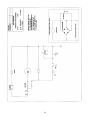
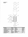
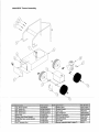
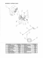
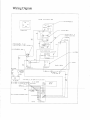
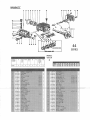
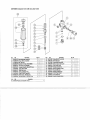
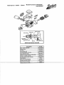
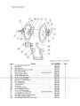
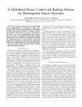
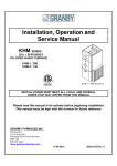
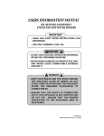
ENDURA MODEL KEH3500GF
Operator’s Manual
Hot Water Pressure Washer
TABLE OF CONTENTS
Important Safety Instructions ............................................................................................................2
Pre-operating Instructions................................................................................................................ 3
Operating Instructions...................................................................................................................... 4
Burner Start-up Instructions ............................................................................................................. 5
Safety Components ......................................................................................................................... 6
Things to Check Regularly............................................................................................................... 7
Specifications and Features............................................................................................................. 8
Major Components & Controls ......................................................................................................... 9
Oil Burner Components, Hose, Gun, & Wand, Couplers ..................................................................10
Trouble Shooting .............................................................................................................................11
Electrical Wiring Diagram.................................................................................................................13
Pump Components ..........................................................................................................................14
Unloader Components .....................................................................................................................15
Warranty..........................................................................................................................................16
1
IMPORTANT SAFETY INSTRUCTIONS
1.
Read all safety and operating instructions before using the unit.
2.
Read warnings on additive containers.
3.
Ventilate work area when using toxic or pungent additives to reduce your exposure to toxic fumes.
4.
Use proctective wear, especially for the eyes and skin.
5.
Be careful of slippery floors. Some additives make a normally safe area extremely slippery and
dangerous.
6.
Keep children away from the machine and wash area.
7.
Do not change nozzle size. Each machine is designed to operate with a specific size nozzle. An
incorrect nozzle could cause excessive pressure resulting in pump damage and possible personal
injury. Refer to parts list for correct nozzle size.
8.
Do not point the nozzle where damage or injury could result. Eg. eyes, skin, people, animals. The
water discharge from this unit is under extremely high pressure.
9.
Do not point the nozzle toward an electrical outlet as you risk severe shock and personal injury.
10. Use only recommended No. 1 or No. 2 fuel oil in this unit. Do not use gasoline, crankcase
drainings, or oil containing gasoline or solvents.
11. Never run the unit in an enclosed area. Exhaust fumes are poisonous. Ensure all areas are properly
vented in accordance with local regulating and/or CSA standard B139.
12. Whenever you stop spraying, always engage the safety latch on the trigger gun.
13. Whenever changing nozzles, always turn the engine off and always relieve the pressure by
triggering the gun. Always engage the safety latch on the trigger gun. Always change the nozzle
with the gun and wand pointed away from you, and never pointed at any person or animal.
WARNING: RISK OF INJECTION OR SEVERE INJURY. KEEP CLEAR OF NOZZLE. DO NOT DIRECT DISCHARGE STREAM
AT PERSONS. THIS EQUIPMENT IS TO BE USED ONLY BY TRAINED OPERATORS.
2
3
PRE-OPERATING INSTRUCTIONS
When unpacking the unit, if you find damage due to shipping, contact your dealer.
INCOMING WATER SUPPLY
Connect a garden hose to the water inlet of the unit. The water supply must be able to deliver 8 gallons
per minute at a minimum pressure of 5 psi.
See “Specifications and Features” sheet in this manual.
OUTGOING (HIGH PRESSURE) WATER
To the water outlet fitting, connect the high pressure hose, trigger gun, extension and nozzle.
PUMP - OIL
Before operating the pump, check to see that the oil is level with the dot on the sight gauge which is
located at the rear of the pump. The oil level can also be checked using the dipstick which is attached to
the oil filler cap. Ensure that the vent hole in the cap/dipstick is clear of dirt. When oil is required, use #20
or #30 non-detergent heavy duty oil.
BURNER - FUEL
FILL THE BURNER FUEL TANK WITH NO. 1 OR NO. 2 FUEL OIL
BATTERY
CAUTION : BATTERY MUST BE INSTALLED BEFORE STARTING THE ENGINE.
(THE ENGINE WILL START WITHOUT THE BATTERY INSTALLED, BUT DAMAGE
WILL OCCUR.)
4
OPERATING INSTRUCTIONS
STARTING THE PRESSURE WASHER
1 Make sure that the burner switch is “OFF”, and that all other switches are in the “OFF” position.
2 Connect water supply to the Washer.
3 Pick up spray gun and hold it firmly, and pull on the gun trigger to evacuate all air in the system.
Release gun trigger.
Never run Washer without water turned on!
STARTING THE ENGINE
1
2
3
4
Hold securely and open the Trigger Gun to reduce the load on the engine.
Turn the Engine Switch on.
Start Engine.
Advance the throttle to bring the engine to full speed.
Caution: The force of the water leaving the nozzle causes a kick-back or recoil at the trigger
gun.
BURNER START UP
• Turn Burner Switch to “ON”.
SEE PAGE 5 FOR DETAILED BURNER START UP INSTRUCTIONS.
WARNING RE BURNER FUEL: DO NOT USE GASOLINE, CRANKCASE OIL, ANY OILCONTAINING GASOLINE, OR ANY OTHER VOLATILE SUBSTANCE.
CAUTION: DO NOT RUN THE FUEL PUMP DRY. ALWAYS CHECK THE FUEL LEVEL IN THE
TANK BEFORE RUNNING THE WASHER.
CHANGING PRESSURE
The variable Unloader Valve is already set to full pressure. Do not adjust the Unloader past the
maximum pressure, as this will not increase the performance, and the excessive shutoff pressure will
damage the Washer.
CLEANING CHEMICALS
For chemical application, insert soap nozzle at the end of the lance. To change concentration, adjust
metering valve toward open or close. Use only chemicals with a PH between 7.0 and 10.0.
STOPPING THE WASHER
•
•
•
•
Ensure Chemical Valve is “OFF”, then shut off Burner Switch.
Pump cold water through the Washer for two minutes.
Retard the throttle until the engine to idling.
Shut off Engine Switch and turn on Trigger Gun to release pressure in the line.
5
BURNER START UP INSTRUCTIONS
(In the event that the burner has been replaced)
1. Set the Thermostat substantially above water temperature of the incoming water supply. (In temperate
regions, this is around 50 degrees Fahrenheit.)
2. Turn on the burner switch.
3. As soon as the burner motor starts rotating, bleed (prime) the fuel pump. To do this, attach the clear
plastic hose over the vent plug. Loosen the plug and catch the fuel in an empty container. Tighten the
plug when all the air appears to be eliminated.
4. If the burner stops during bleeding, wait three to five minutes for the control Safety Switch to cool,
then reset it manually.
5. If the burner stops after flame is established, additional venting is probably required. Repeat the
bleeding procedure.
CAUTION: Do not attempt to start the burner when excess fuel has accumulated, or when the
furnace or boiler is full of vapor, or when the combustion chamber is hot.
ADJUSTING THE BURNER
NOTE: The settings below have already been completed for this unit, so the following
instructions for adjusting apply only if a new burner or coil is installed.
1. Allow sufficient air to obtain a clean looking flame by loosening the lock screws and moving the air
shutter, and if necessary, the bulk air band.
2. Draft Control Adjustments: The unit is set up in the factory to burn cleanly into atmospheric
conditions. Therefore if a chimney is fitted to the machine, an “O” draft would be the optimum
condition.
3. Final Air-Adjustments: Allow at least ten minutes for warm-up, and longer if the unit is new, in order
to burn off the oil deposits on the heat exchanger and other surfaces. Check and adjust all controls.
(See Manufacturer’s Instructions sheets.) Test the primary control Safety Switch to insure a safety
shutdown will occur in the event of equipment malfunction.
6
SAFETY COMPONENTS
UNLOADER VALVE
The Unloader Valve allows all of the water delivered by the pump to return to the pump suction
side. If the trigger gun is closed or “OFF”, the Unloader Valve goes into the “bypass mode” and
the pump runs without pressure. HOWEVER, THE PUMP MAY BE SEVERELY DAMAGED,
DUE TO EXCESSIVE OVERHEATING, IF LEFT RUNNING IN THE “BYPASS MODE” OR
“GUN-OFF” SITUATION FOR MORE THAN 6 MINUTES.
SAFETY RELIEF VALVE
The Relief Valve prevents the machine from being subjected to abnormally high pressures. If
this situation occurs, the valve will blow off relieving the pressure in the coil. This valve may also
operate if the unloader is adjusted too high.
PRESSURE SWITCH
The Pressure Switch ensures that there is pressure, and therefore there is water flow at the
head of the pump. This control does not operate at less than 300 psi. Therefore if the pump is
on “bypass mode”, the burner will not operate.
THERMOSTAT
The built-in thermostat allows temperature adjustment up to 212 °F.
7
THINGS TO CHECK REGULARLY
1. Check for SYSTEM LEAKS. Leaks in the pressure side of the system can cause premature wear (or
even failure) of the pump. The WARNING signal for this kind of leak is “frequent” cycling of the
unloader. (“FREQUENT” means more than once every 2 minutes in the “Gun-Off” position.) Check
the gun and swivel joints for leaks.
2. Check the OIL LEVEL at least once a week. Add ONLY the type and grade of oil specified for this
pump. (See “Specifications and Features” sheet.)
3. CHANGE OIL as recommended.
4. After you use chemical additives, thoroughly FLUSH the system with clean water.
5. Never run the washer without water. TURN WATER ON FIRST.
6. PROTECT FROM FREEZING! When transporting your washer in temperatures below 32°F (0°C),
WINTERIZE the pump, hoses and gun.
HOW TO WINTERIZE YOUR PRESSURE WASHER
1. Shut off the water supply, and disconnect hose.
2. You need a short (2’) length of hose with a male garden hose fitting on one end.
3. Connect the short hose to the inlet of the machine.
4. Put the other end of the water hose into a container of windshield washer or anti-freeze.
5. Turn on the Cleaner and open gun until liquid comes out of the nozzle “foamy” or “soapy”.
6. Put gun in “OFF” position for 5 seconds to get anti-freeze into bypass line. Shut off motor, unit is now
winterized.
8
SPECIFICATIONS AND FEATURES
HOT
WATER
MODE
VOLTAGES
Pressure PSI
Volume GPM (US)
Nozzle Size
Water Temperature °F
Engine Gas HP
3500
3.8
4.0
(175-212)*
13
12 Volt Burner
BURNER
Burner BTU’s
Firing Rate GPH (US)
Fuel Pressure PSI
Fuel Nozzle (80° angle)
Fuel type
289,000
1.98
140
175
No. 1 or No. 2 Fuel Oil
SAFETY
COMPONENTS
Unloader
Pressure Switch
Adjustable Thermostat
Pressure Relief Valve
Standard
Standard
Standard
Standard
Gun
Wand
Hose
Portable model
Paint – Epoxy Powder
Downstream Injector
Coil – Pipe Schedule
Pump MFG
Oil for Pump
Dimensions (LxWxH) in. (Crated)
Weight (pounds) (Shipping)
Shut-Off Gun 4500 PSI
48” Lance
50 Ft. 250°F Rating
Standard
Standard
Standard
80
Interpump
SAE 20W or 30W
50x35x57
440
FEATURES
* Note: water temperature varies with the volume and pressure settings, and the water inlet temperature
9
MAJOR COMPONENTS
Cap HW24559
Down Stream Injector
HWPHDI21
Fuel Cap for fuel oil tank
HW201634B
Skin HW24558
Frame HW24570B
Coil Shed 80 Pipe
HW40055
Unloader UVP280
Blow Off Valve
HWRV500B1
Pump WW965BCRS
13” Wheel HW40554A
Axle Cap HW40558
Pressure Switch PSW1
Toggle Switch
HWELV1DAB6011RZ
Thermostat HWTR86
Engine 13 HP Honda
Nota
Engine Manual is Included with each Unit
10
Ignition Transformer
HW51499U
Fuel Solenoid
HW7304
Motor
HW21557
Fuel Pump
HW2460U
JB301 Beckett Burner ADC –12 Volts
Wix Fuel Oil filter
HW33001
Hose
HW504000
Plug
HW22209FP
Socket
HW22208FP
Hose 50 Ft.
Gun
G250VA
Socket QC7214
Wand
L1200SS
Gun & Wand
11
TROUBLE SHOOTING
TROUBLE
POSSIBLE CAUSE
Low Pressure
Leaks in water system
Tighten all fittings.
Insufficient water supply
Fill tank or increase line size to
machine.
Outlet orifice worn or wrong size
Replace with correct orifice.
CAUTION: Do not use smaller than
recommended. Excessive pressure will
damage pump.
Gun control unloader valve bypass
leak
Repair or replace unloader valve.
Dirty or worn check valves in pump
Replace or clean. Refer to high
pressure pump manual.
Cylinder cups leaking and/or worn
cylinder sleeves
Replace. Refer to high pressure pump
manual.
Outlet orifice restricted
Remove orifice at tip of gun and clean.
Flush coil with water before replacing.
Scale or dirt in coils
De-scale coils.
Pump speed too high
Check water output GPM.
Relief valve set at low pressure
Re-adjust relief valve.
Relief valve dripping after
adjustment
Replace valve.
Unloader valve stuck
Repair unloader valve.
Clogged soap screens
Clean or replace.
Air leak around soap siphon check
valve and/or metering valve leaking
Tighten all fittings and tubing.
Excessive
Pressure
Relief Valve
Operates
Weak or no chemical at
nozzle
REMEDY
12
TROUBLE SHOOTING (CONTINUED)
TROUBLE
POSSIBLE CAUSE
Burner will not ignite
No fuel
Fill fuel tank and check fuel filter for water and
other contaminants.
Electrodes out of alignment
Adjust.
Electrode insulator failure
Check for breaks, cracks, or spark trails –
Replace.
Water flow switch not closing
Adjust, repair or replace.
Fuel solenoid valve not
opening
Clean, repair or replace.
Weak transformer
Clean and check transformer terminals.
Replace if necessary. Check for spark.
Plugged oil nozzle
Replace (do not clean).
Faulty burner oil pump
Adjust or replace.
Improper fuel
Use No. 1 or No. 2 Fuel oil.
Air to burner insufficient
Air adjustment or burner –
Remove soot from coils.
Fuel nozzle interior loose
Replace nozzle.
Thermostat adjustment
Adjust the thermostat to desired temperature.
Coils liming up
Descale.
Improper combustion
Readjust burner.
Unit smokes
Water temperature too low
REMEDY
13
14
15