1
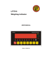
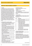
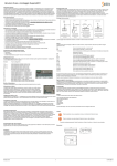
OP-903
Portable Static Weighing Indicator
User’s Manual
Safety Instruction
For safety operation pls. follow the safety instruction.
WARNING
Setting. Calibration Inspection and Maintain of the indicator is prohibited by Non-professional staff.
WARNING
Pls. make sure the weighing display have good ground in using.
WARNING
The indicator is the static and sensitive equipment,cut off the
power during electrical connections, internal components
touched by hand is prohibited, and please take the measure of
anti-static.
LIST
LIST ........................................................................................................................................... 1
1. PRODUCT INTRODUCTION ................................................................................................ 1
1.1 MAIN FUNCTION ................................................................................................................. 1
1.2 TECHNICAL PARAMETER ...................................................................................................... 1
1.3 DRAWING ........................................................................................................................... 2
1.4 BATTERY INSTRUCTION ....................................................................................................... 2
2. INSTALLATION AND CALIBRATION .................................................................................. 2
2.1 CHECK............................................................................................................................... 2
2.2POWER SUPPLY CONNECTION .............................................................................................. 2
2.3 CONNECTION OF LOAD CELL AND INDICATOR......................................................................... 3
2.4 COMMUNICATION INTERFACE ............................................................................................... 4
3. BASIC OPERATION ............................................................................................................. 5
3.1 KEYPAD .............................................................................................................................. 5
3.2 POWER ON & OFF ............................................................................................................... 6
3.3 ZERO OPERATION ............................................................................................................... 6
3.4 TARE OPERATION ................................................................................................................ 6
3.5 UNIT SWITCH ..................................................................................................................... 6
3.6 CHECKING ......................................................................................................................... 6
3.7 SWITCHING ........................................................................................................................ 7
3.8 PRINTING ........................................................................................................................... 7
4. CALIBRATION AND PARAMETER SETTING ..................................................................... 7
4.1 ENTER SETTING.................................................................................................................. 7
4.2 STEP OF CALIBRATION OPERATION ....................................................................................... 7
4.3 APPLICATION FUNCTION PARAMETERS SETTING CHART.......................................................... 9
5.SERIAL INTERFACE RECEPTION COMMAND..................................................................11
5.1 COMMAND 1 ......................................................................................................................11
5.2 COMMAND 2......................................................................................................................11
6.PRINT FORMAT....................................................................................................................11
6.1 NORMAL PRINTING FORMAT ...............................................................................................11
6.2 ACCUMULATIVE PRINTING FORMAT ..................................................................................... 12
7.MAINTENANCE ................................................................................................................... 13
7.1 REGULAR ERROR AND SOLUTION ....................................................................................... 13
7.2 DAILY MAINTAIN ................................................................................................................ 14
7.3PACKING LIST .................................................................................................................... 15
1. Product Introduction
1.1 Main Function
Portable Static Weighing Indicator OP-903 is designed for static axle scale. It can
connect with 1,2,3,4 weighing pads to weigh the truck. It owns manual weighing mode and
automatic weighing mode. It can be normal weighing or accumulative weighing. Varied
weighing ways to meet different requirements.
LCD display (size: 136mm x 36.5mm) show the real weight date on the weighing pad.
The unit KG/LB display can be adjusted by the key on the instrument. At same time, the
percentage of each pad on the total weighing is displayed too. Other function includes tare,
zero, print, save, check, delete.
The power supply by 6v/4.5Ah battery and it can be recharged by 9v/1.2A adapter.
Built-in needle printer, several printing formats; RS232/485 interface for large display or
computer; The calendar is in the software. Date and time can be checked easily. Easy
operation, high precision, good application.
1.2 Technical parameter
>> Sensitivity
0.5uv/d
>> Input voltage
-30~30mV
>> Accuracy class
III
>> Initial zero range
±10%Max
>> Manually zero range
±2% Max
>> Zero Range
100% Max
>> Zero Tracking
0.5d/s
>> Excitation circuit
VDC,6 wire connection,Maximum connect 24 load cell of 350Ω
>> AC power
100~240VAC,50/60HZ
>> Operation temperature humidity
>> Storage temperature
-10℃~+40℃,≤90%RH
-10℃~+40℃
1
1.3 drawing
1.4 Battery instruction
1. when you use the internal battery first time,you should charge the battery fully, to
prevent low voltage resulted from self leakage of battery.
2. when the “
3. when
” is flashing, it means low battery, pls. charge it in time.
and no flashing, it means fully charged
4. if battery is not used for long time, take it out to avoid the leakage.
5. In order to keep the battery in best using condition, it is suggest that you fully
discharge the battery every month, the method is that using the indicator till it is
automatically power off.
2. Installation and calibration
2.1 Check
Open the box and check all items according to the packing list. If som missed or
broken, please contact with our company immediately.
2.2Power supply connection
The indicator is powered by adapter, you plug the adapter directly into the “DC” pin at
the back cover the indicator is ok.
2
2.3 Connection of load cell and indicator
The indicator can connect with 4 weighing pads or 24 pcs of load cells 350Ω at most.
Quick disconnect of load cell as below.
The number of weighing pads and load cells correspond to the weighing modes. If the
pads or load cells are connected at the right way, the indicator can’t work. Please pay
attention to the below.
Number of
weighing pad
Load cell connection
Weighing mode
1
LFW
[ModE 1]Setting “1”
2
LFW,RFW
[ModE 2]Setting “2”
3
LFW,LRW,RRW
[ModE 3]Setting “3”
4
LFW,RFW,LRW,RRW
[ModE 4]Setting “4”
Normal weighing mode and accumulative weighing mode can work with the printer to
print the weighing data.
Normal Weighing mode:
To set the printing format “1”, the indicator is in normal weighing mode. It can connect
1/2/3/4/ pads to weigh and “Print” the weighing data and save.
Example:3 weighing pads connect with indicator to weigh the airplane.
a. The pads should connect with LFW,LRW,RRW interfaces;
b. parameter setting:working mode[ModE 3]setting “3”;printing format[PF - 1]setting
“1”;
c. Drive the plane on the pads. Press “switch” button, indicator can display the total
weight and the weight of each pad and the percentage of each pad weight from the
total weight.If printing format setting”1”, the weighing data can print automatically and
save after stable.If printing format setting”0”, the weighing data will print and save
manually.
Accumulative weighing mode:
To set printing format ”2”, the indicator is in accumulative weighing mode. Now 2/4
pads should be connected with the indicator. And press ”store” button to accumulate the
axle weigh and print. Then press “printing” to print the final accumulative weight and
3
save.
Example:Two pads work with the indicator to weigh a truck with three axles.
a. The pads should connect with LFW,RFW interfaces;
b. Parameter setting:working mode[ModE 2] setting“2”;printing format[PF 2]setting“2”;Axles [ALE - 3]setting“3”.
c. Drive the first axle of the truck on the weighing pads. Press ”Switch” button,
indicator can display the axle weight and the each weight of the wheels and the
percentage of each wheel weight from the axle weight. If printing format setting “1”, the
weighing data can print and save automatically after weighing stable;If printing format
setting”0”, the weighing data will print and save manually by press “ store” button.
d. Drive the second axle of the truck on the weighing pads and repeat the operation
same as step C, accumulate and print the second axle weight.
e. Drive the second axle of the truck on the weighing pads and repeat the operation
same as step C, accumulate and print the third axle weight.
f. After finishing the weight for three axles, if printing format setting”1”, the total weight
will print and save automatically; If printing format”0”, it will print manually by press ”print”
button.
2.4 Communication interface
RS232 :DB9 Pin definition as below.
Pin function and definition as bellows:
DB9 joint
Definition
Function
2
TXD
Sending data
3
RXD
Receiving data
5
GND
Ground interface
4
3. Basic operation
3.1 keypad
LCD
Instruction
Weighing data
Kg/lb
Weighing unit: kg/lb
Percentage,show how many percentage the pad weight take on
the whole weight
Tare
Tare
Gross
Gross weight
Net
Net weight
The weighing data is stable
Weight is zero
LFW
The weight of the left front wheel
RFW
The weight of the right front wheel
LRW
The weight of the left back wheel
RRW
The weight of the right back wheel
Total
Go to accumulation mode
Keys function
Key name
Key function
Print
1.Printing the weighing data as weighing.
2.Working with the switch button to get into the menu of
calibration.
Store
In accumulative weighing mode, to accumulate the axle weight
and print the weight data.
5
Zero
Zero the weight within tolerance
Tare
At G.W mode, get the tare weight. At N.W mode, clear the tare,
get the G.W
Kg/lb
Covert between kg and lb
Check
Check and read the saved weight data to print.
Switch
Switch the weight between the pad weight and the total weight.
on/off
Press 2 seconds to power on or power off
3.2 Power on & off
Press 2 seconds to power on or power off. After power on, indicator self inspection,
please check the display is normal or not, LCD light then show the voltage of the battery.
Finally into weighing mode.
3.3 Zero operation
Within the tolerance, “Zero” key clear the weight on all weighing pads. When the pads
unstable or loading over zero range or on tare mode, indicator can’t ZERO and show
ERROR.
3.4 Tare operation
In normal weighing mode, press ”Tare” button to make the load be tare weight; In
accumulative weighing mode, press “Tare” button to preset the tare weight and press
“ print” button to confirm the tare weight. The lights on the keypad is showing. In Tare
mode, press “Tare” button to deduct the tare weight from the total weight and show the net
weight.
NOTE:Tare mode only show on the total weight display.
3.5 Unit Switch
To press “Unit” button for switching the unit between “KG” and “LB”.
3.6 Checking
Weighing mode, press “Check” button to show “C 0030” (30 records existing), input
“C 0020” and press “ Print” to check 20th record. Display show “REAd-0”. Choosing”1” to
show date, time, axle, tare weight and total weight one by one. Then “Print 0”, choosing
“1” to print this record and back to the Checking display “C 0020”. Press “Check” Button
again to quit and back to weighing mode.
6
3.7 Switching
Weighing mode, press “Switch” button to change the display between the axle weight
and the total weight.
3.8 Printing
Manual weighing, press “print” button to print when the pad is stable.
Note:
1.Automatic accumulative weighing mode, press “Print” to print the total weight even if the
number of axle don’t reach the setting number.
2.Press”store”and “print”,to add the current weight data printing.
4. Calibration and Parameter setting
4.1 Enter setting
Press “ Switch” button and “ Print” button together to enter into the menu for setting
F1-F5.
The key functions in setting:
ENTER
UP
DOWN
LEFT
RIGHT
EXIT THE MENU
4.2 Step of calibration operation
F1 menu:setting working mode, unit, decimal, graduation and span.
Step
Operation
Display
[F
1
1]
Remark
F1 menu
[Mode 2]
Weighing pad working mode:1/2/3/4
press
7
2
press
[Unit-0]
Unit:0/1(kg/lb)
[dot--2]
Point number:0/1/2/3/4
or
press
3
press
or
press
4
[E - 05]
press
Graduation setting:1,2,5,10,20,50。
or
press
5
press
or
[Full-0]
[Full-1]
0:no change of max capacity
1:change the max capacity
[0500.00]
[1000.00]
Setting the max span
Default division:10000,
display 500.00.
The max. span is 1000.00
press
6
press
or
/
or
press
F2 menu: Zero, loading calibration, save the calibration parameter.
Step
Operation
Display
[F
1
2]
Remark
F2 menu
[SCALE2]
Pad choose:calibration for the 2nd pad
[CAL--0]
[CAL--1]
[
9]
[
0]
Zero Calibration:
0=No need calibration
1= need calibration
[SPAN-0]
[SPAN-1]
0=No need loading calibration
1=loading calibration
[0100.00]
Loading calibration:
Setting loading 100,00 an put the
100kg weight on the 2nd pad.
Loading choice: load the weight as
possible
press
2
press
or
press
or press
3
press
or
press
or press
press
or
/
or
[
[
9]
0]
press
8
As max capacity, at least 10%
4
press
or
[SAVE-0]
[SAVE-1]
0=non-save the loading parameter
1=save the loading parameter
press
4.3 Application function parameters setting chart
Step
Operation
Display
[F
1
Remark
3]
F3 menu
[ALE-02]
The number of axle settings
In accumulative weighing mode, the
number of axle should be pre-setted.
[SN--23]
Cargo number setting
[PF - 1]
Printing format setting
0: No printing
1:normal printing format for normal
weighing.
2:Accumulative printing format for
accumulative weighing.
[PM - 1]
Printing method
0: manual
1:automatic
[PC - 1]
Printing coupon numbers setting
1/2/3
[Baud-1]
Baud rating setting
0:600; 1:1200; 2:2400;
3:4800 4:9600; 5:19200;
6:38400 7:57600; 8:115200
[CP - 1]
Communication setting
0: communication off.
1: communication format 1 for PC.
2:communication format 2 for second
display(YAO HUA MODEL).
3.communication format 3 for second
display(TOLEDO MODEL).
press
2
press
or
press
3
press
or
press
4
press
or
press
5
press
or
press
6
press
or
press
7
press
or
press
9
8
press
or
/
or
[OFF-00]
[OFF-10]
Automatic power off setting:
00: no power-off
Automatic power-offer after ten min.
or
/
or
[BL--00]
[BL--10]
Back lit setting
00:Back lit on
10:Back lit off after ten seconds.
Backlist off: in zero condition and no
operation.
[Date-0]
[Date-2]
Date format.
Format 0:year,month,day
Format 1:month,day,year
Format 2:day,month,year
[30.07.13]
Date setting:
[11.08.13]
press
9
press
press
10
press
or
press
11
press
or
/
or
[11.08.13]
press
12
[14:13:20]
press
or
/
Time setting:
[15:17:30]
or
[15:17:30]
press
Step
Operation
Display
[F
1
Remark
4]
F4 menu
[S-0560]
560 records in indicator. Max. recording
is 2000 cps.
[HE-1.0A]
PCB version 1.0A
[SE-1.00]
Software version 1.00
[LFW
code]
Check the left front wheel ad code
press
[RFW
code]
Check the right front wheel ad code
press
[LRW
code]
Check the left back wheel ad code
press
[RRW
code]
Check the right back wheel ad code
press
press
2
press
3
press
4
5
6
7
Ste
p
Operation
Display
Remark
10
[F
1
press
2
press
or
5]
F5 menu
[dELA-0]
[dEAl-1]
0:No deleting the weighing record.
1:Deleting the weighing record.
[dEAL-0]
[dEAL-1]
0:No deleting all the records.
1:deleting all the records.
press
5.Serial interface reception command
5.1 Command 1
(RS232COM serial interface can receive simple ASCII command)
RS232 parameter:9600Bit/S Baud rate,8 digits,no check point,1 stop.
,
S0 S 1
,
S2
CR
S3
Data
LF
S4
S1: weight status, ST= standstill, US= not standstill, OL= overload
S2: weight mode, GS= gross mode, NT= net mode
S3: weight of positive and negative, “+” or ” –“
S4:“kg” or “lb”
Data: weight value, including decimal point
CR: carriage return
LF: line feed
5.2 Command 2
(workable with second display from Yaohua, Baud rate 600)
6.Print format
6.1 Normal Printing format
Single pad:
Double pads:
Three pads:
Four pads:
WEIGHTING REPORT
WEIGHTING REPORT
WEIGHTING REPORT
WEIGHTING REPORT
11
------------------------------
------------------------------
------------------------------
------------------------------
NO. : 0575
NO. : 0575
NO. : 0575
NO. : 0575
Date: 2013-11-02
Date: 2013-11-02
Date: 2013-11-02
Date: 2013-11-02
Time: 09:59:04
Time: 09:59:04
Time: 09:59:04
Time: 09:59:04
Vehicle:
Vehicle:
Vehicle:
Vehicle:
Cargo:34
Cargo:34
Cargo:34
Cargo:34
LFW: 429.0kg
LFW:429.0kg
FW:
LFW: 429.0kg
----------------
RFW:413.5kg
LRW: 319.0kg
RFW: 413.5kg
Net: 429.0kg
Axle1:842.5kg
RRW: 293.0kg
Axle1: 842.5kg
Tare:0.0kg
----------------
Axle2:
LRW: 319.0kg
Net:842.5kg
----------------
RRW: 293.0kg
Net: 1041.0kg
Axle2: 612.0kg
Tare:0.0kg
-------------------
Gross: 1041.0kg
Net: 1454.5kg
Operator:
Tare:0.0kg
Gross: 429.0kg
Operator:
Tare:0.0kg
Gross:
842.5kg
Operator:
429.0kg
612.0kg
Gross: 1454.5kg
Operator:
6.2 Accumulative printing format
Double pads(Double axles)
Four pads:
(Four axles)
WEIGHTING REPORT
WEIGHTING REPORT
------------------------------
------------------------------
NO. : 0594
NO. : 0594
Date: 2013-11-02
Date: 2013-11-02
Time: 11:10:41
Time: 11:10:41
Vehicle:
Vehicle:
Cargo:34
Cargo:34
LW: 420.5kg
LFW:
RW: 419.5kg
RFW: 419.5kg
Axle01:
Axle01:
840.0kg
420.5kg
840.0kg
LW: 309.5kg
LRW:
RW: 297.0kg
RRW: 297.0kg
Axle02:
Axle02:
607.0kg
309.5kg
607.0kg
------------------------------
LFW:
420.5kg
Net: 1447.0kg
RFW: 419.5kg
Tare:0.0kg
Axle03:
Gross: 1447.0kg
LRW:
Operater:
RRW: 297.0kg
840.0kg
309.5kg
Axle04:
607.0kg
-----------------------------Net:
12
2894.0kg
Tare:0.0kg
Gross:
2894.0kg
Operater:
7.Maintenance
7.1 Regular error and solution
ERROR
REASON
SOLUTION
1.Overload
2.wrong
connection
with load cell
3. load cell has quality
problem.
1. reduce the weight
2. check load cell connection
3. inspection load cell. Check
the input and output
1.calibration is no good
2. wrong connection
3. load cell has quality
problem
1. check scale is resisted or
not, foot is kept level or not.
2. check load cell connection.
3. checking load cell
ERR10
Zering, not on stable
weighing condition.
Zering, on stable weighing
condition
ERR11
Zero and tare at same
time.
Back to G.W, then Zero
Out of the zero range
Move the extra load
ERR15
Tare, no on stable
weighing condition
Tare after stable weighing
ERR16
Tare when no load
To load some, then tare
ERR17
Out of tare range
Decrease the tare weight
ERR25
The S/N number wrong
when checking the
weighing record
Assure the S/N number within
the
Number of records
ERR30
Printing format wrong
at accumulative
weighing mode
Printing format setting”2”
ERR31
Working mode wrong at
accumulative weighing
mode
Working mode setting”2/4”
ERR32
Weighing over the span
Or display range or
unstable or failure of
Load properly at zeroing, then
printing after data stable.
UUUUUU
nnnnnnn
ERR12
13
zero at accumulative
weighing mode.
ERR33
Display Error, Printing
with the indicator at
accumulative weighing
mode.
Print the total weight after
accumulating the weight of
axles.
ERR34
Printing error at normal
Weighing mode.
Stable then printing
ERR35
Printing format wrong at
normal weighing mode.
Setting”1”
7.2 Daily maintain
1.Protect the indicator from strong sunlight to prolong the using life.
2.Good connection between load cell and indicator. Far from away from strong electric
field, magnetic field.
3.Power off the indicator when lightning.
4.Power off the indicator firstly before plug and unplug.
14
7.3Packing list
Packing list
S/N
1
ITEM
NAME
Weighing
indicator
UNIT
QTY
PCS
1
2
Plastic bag
PCS
1
3
Accessories bag
PCS
1
China/DC9V
PCS
1
US/DC9V
PCS
1
UK/DC/9V
PCS
1
EU/DC9V
PCS
1
AU/DC9V
PCS
1
OTHERS
PCS
1
PCS
1
PCS
1
PCS
4
PCS
1
4
Adapter
5
USER MANUAL
6
RS232
DB9 头
LOADCELL
5 PIN Quick
PLUG
disconnect
8
Bracket
Wall-mounted
9
Certificate
PCS
1
10
Packing list
PCS
1
7
15
PACKING