1
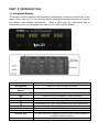
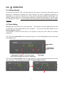
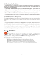
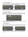
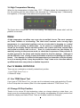
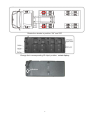
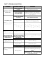
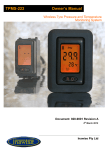
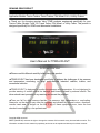
GENUINE OEM PRODUCT
Application Models: Tractor Trailers, Travel Trailers, Fifth Wheel R V’s, & Utility Trailers
● Thank you for choosing genuine Valor TPMS products engineered specifically for your
Tractor Trailer, Straight Truck, RV Travel Trailer, Fifth Wheel, or Utility Trailer. This product is
designed specifically for OEM’s and aftermarket installations.
User’s Manual for TPMS-203-RVT
The Second Edition “OEM”
▲Please read this Manual carefully before using this product.
▲TPMS-203-RVT has been developed specifically to address the challenges of tire pressure
and temperature monitoring on large multi-wheeled Industrial vehicles, trailers, and
recreational vehicles.
▲TPMS-203-RVT is designed to monitor tire pressure and temperature. It is not designed to
provide warning of sudden critical tire damage and blowout caused by external effects. The
driver should react promptly to any warning and correct the problem.
▲Tires can fail for other reasons besides low pressure, high temperature or overloading.
Always be on the alert for any other tire problems as indicated by unusual noises, vibrations,
uneven tread wear, or bulges on the tire! If any of these symptoms occur, have the tires
checked immediately by a tire professional!
Copyright 2009 reserved
SBAC (VALOR HK) reserves the right to change the contents of this manual at any time and without notice. The
information contained in this manual is proprietary and must not be reproduced without prior written consent.
ATTENTION
Default values have been assigned to each sensor for the following:
Baseline Pressure – default value, MUST be reset by user according to SCIP
Low Pressure Warning – -20% deviation from baseline pressure
High Pressure Warning – +30% deviation from baseline pressure
High Temperature Warning – set to alarm at 176℉
Leakage Warning – air lost is more than 4.8PSI in 16 seconds
The sensors supplied with the TPMS system installed on your trailer are designed specifically
for rating of the tires as listed below.
Part No.
Tire Load
Rating
Standard Cold
Inflation
Pressure
Low Pressure
Warning Limit
High Pressure
Warning Limit
44104
C
50
20% decrease
from set pressure
30% increase
from set pressure
44106
D
65
20% decrease
from set pressure
30% increase
from set pressure
44108
E
80
20% decrease
from set pressure
30% increase
from set pressure
110302040232
F+
110
20% decrease
from set pressure
30% increase
from set pressure
TABLE OF CONTENTS
PART I INTRODUCTION ........................................................................................................................ 2
1.1 INTEGRATED DISPLAY ............................................................................................................................................ 2
Part Ⅱ OPERATION ................................................................................................................................ 3
2.1 GETTING STARTED ................................................................................................................................................ 3
2.2 TIME SETTING ........................................................................................................................................................ 4
2.3 SETTING BASELINE PRESSURE ............................................................................................................................ 4
2.4 CHECKING TIRE CONDITIONS .............................................................................................................................. 4
2.5 DATA DOWNLOAD & M ANAGEMENT ..................................................................................................................... 5
Part Ⅲ WARNINGS ................................................................................................................................. 5
3.1 LOW PRESSURE WARNING ................................................................................................................................... 5
3.2 HIGH PRESSURE WARNING................................................................................................................................... 6
3.3 LEAKAGE WARNING .............................................................................................................................................. 6
3.4 HIGH TEMPERATURE WARNING ............................................................................................................................ 6
Part IⅤ WHEEL ROTATION.................................................................................................................... 8
5.1 USE TPMS SMART TOOL ..................................................................................................................................... 8
5.2 CHANGE ID CHIP POSITION .................................................................................................................................. 8
PART V TROUBLE SHOOTING ................................................................................................................ 9
PART VI PRODUCT SPECIFICATIONS ................................................................................................. 11
PART VII CERTIFICATES & AWARD ................................................................................................... 12
8.1 FCC'S AUTHENTICATION ANNOUNCEMENT......................................................................................................... 12
8.2 EUROPEAN REGULATIONS ANNOUNCEMENTS .................................................................................................... 12
8.3 CE DIRECTIVE ANNOUNCEMENT.......................................................................................................................... 12
PART VIII WARRANTY POLICY ........................................................................................................ 13
PART Ⅰ INTRODUCTION
1.1 Integrated Display
The display monitors pressure and temperature information of each tire continuously. It can
report 3 axles with up to 12 tire’s data as well as allowing the baseline pressure to be set to
suit different axle loading requirements. When a trailer with the Valor trailer box is
connected to the truck the display can report up to 6 axles with 24 wheels.
Controls and Indicators
Axle Switch
Pressure & Temperature
Switch
Axle Indicator
Bar
o
F
Switch
Buzzer
Set Key
ID Chip Slot
Mini USB Port
Functions
Press it to cycle through each axle
Press it to switch from pressure to temperature readings
Display cycles through six axles
Pressure unit (PSI supplied in North America)
Temperature unit ( Fahrenheit supplied in North America)
Leakage icon
Abnormality icon: low / high pressure and high temperature
Turns display on or off
Gives audible alert for tire issues
Press it to set baseline pressures
ID chips are used to register Chip’s ID code into the display to
recognize wheel positions
To download data from display via RS232 cable
2
Part Ⅱ OPERATION
2.1 Getting Started
The screen will remain “000” until the data from its sensor is received. After data from all
sensors is received the display will cycle through the axles, displaying pressure or
temperature, at 5 second intervals or until an alert or warning condition is detected. The
display supplied with your unit has been calibrated in Degrees Fahrenheit (F) and Pounds
per Square Inch (PSI). If a tire location does not have a chip the position will not show
anything.
2.2 Time Setting
Managing the tire data can be very important. This system can store significant amounts
of data that can be downloaded to your computer. You can see the data details via our
PressureAgent software.
It’s important to set time (local time) in the system so that you know when the incident
happened.
.
2.2.1 Press the Axle Switch for 8 seconds to get into Time Setting Mode and you will hear
the display beep.
2.2.2 Press the Axle Switch swiftly to look up the time “year-month-day-week-hour-minute”
value circularly. The following time is 22:57, Tuesday, May 25, 2010.
3
2.2.3 Press the Pressure & Temp. Switch to change the time value.
2.2.4 Press the Axle Switch for 8 seconds to exit time setting mode and you will hear the
display beep.
2.3 Setting Baseline Pressure
--- The display has the ability to have the baseline pressure set for each wheel. The factory
setting for the baseline pressure is set at 87.5 PSI. It must be reset once the system is
installed or a sensor is changed.
--- To set the baseline, simply inflate the tires to the correct operational pressure.
--- locate the set Key (shown below) on the back of the unit located next to the power button.
Depress the Set Key and hold for 5 seconds until a “Beep” is heard. This confirms that the
baseline pressure has been reset.
--- To confirm the new baseline setting press the set button quickly and the display will
show the baseline settings.
Set Key
4
2.4 Checking Tire Conditions
--- After data from all of the sensors is received, the display will show each axle’s data for 5
seconds and automatically shift to next axle if all tires are normal. You can also press the
Axle Switch to shift axles quickly.
--- The display will automatically go to any axle with a wheel issue. When there are
multiple wheel issues the display will scroll between the axles with the problems.
--- If the pressure warning and temperature warning exist in the same axle, the display will
just show the pressure warning of this axle.
--- Press the “Pressure & Temperature Switch” to switch from pressure to temperature.
--- If no data is received from the tire in 20 minutes it will show up as dashes on the display.
2.5 Data Download & Management
The integrated display unit can read up to 24 wheels’ data at one time and store more than
8000 lines of data, on a first in first out basis. This data can be downloaded two different
ways.
• It can be downloaded by connecting to a hand tool via a download cable. The hand tool
has a SD card slot. Data can be stored on the SD card and transferred to the desktop later.
• It can be transferred to your laptop computer via an RS232 connector cable. This cable
is not supplied with the system but can be purchased separately. The cable comes with
software for viewing and monitoring tire conditions.
Part Ⅲ WARNINGS
Warning indicates that you are operating your vehicle in a dangerous
condition. When the abnormality icon
illuminates, STOP AND CHECK your
tire(s) as soon as safely possible and inflate them to the proper pressure.
The system has four types of warning modes
● 20% below the baseline pressure for the Low Pressure Warning;
● 30% above the baseline pressure for the High Pressure Warning;
● 4.78PSI is lost from the tire in 16 seconds for the Leakage Warning;
● Temperature in the tire is over 176℉ for the High Temperature Warning.
5
3.1 Low Pressure Warning
When actual pressure in the tire is 20% lower than baseline pressure: ①Display shows the
tire position, axle number and current tire pressure of the abnormal tire; ②Warning beep;
③Abnormality icon appears; ④The abnormal tire position flashes.
The figure above shows tire “1B” and”2A” are under-inflated. The display just shows axle1
and axle2 until the problems are corrected (1 bar is equal to 14.5 psi, 4.5 bar is 65 psi).
3.2 High Pressure Warning
When the actual tire pressure is 30% higher than the baseline pressure: ①Display shows
the current tire pressure, the position & axle number with the abnormal tire; ②Warning
beep; ③Abnormality icon appears; ④The digits of abnormal tire position flash.
The figure above shows tire “3B” is over-inflated and tire “3A” is under-inflated. The display
just shows axle 3 until the problems are corrected.
3.3 Leakage Warning
When 4.78PSI is lost from the tire in 16 seconds: ①Display shows the tire location and tire
pressure; ②Warning beep; ③Leakage icon appears; ④The digits of abnormal tire position
flash.
The figure above shows tire “2C” is leaking and tire “1A” is over heating (88 degrees C is
equivalent to 190 degrees F). The display just shows axle1 and axle2 until the problems are
corrected.
6
3.4 High Temperature Warning
When the tire temperature is higher than 176℉: ①Display shows the temperature of the
tire, the position and the axle number with abnormal tire; ②Warning beep; ③Abnormality
icon appears; ④The digits of the abnormal tire position flash.
The figure above shows tire “1A” is over heating. The display just shows axle1 until the
problem is corrected.
Note:
A high temperature condition can occur due to multiple issues. The most common
are under inflation or overloading. The third most common issue causing high
temperature is a mechanical problem such as a brake that is dragging or a wheel
bearing that is starting to malfunction. In all cases if a temperature warning is
shown on the display caution should be taken, the vehicle should be slowed down
and pulled over when safe to do so. Once in a safe location use the display, by
manually moving to the pressure mode, to check the tire pressure. If the pressure is
ok then proceed to the wheel and visually check the tires for damage. Although it
will be difficult to see, visually inspect the brakes and axle end (bearing) for obvious
issues. If no damage is visible and the temperature has lowered so that the display
is not in a warning mode, it may be possible to “limp” home or to a location where a
qualified technician can perform a detailed inspection.
Part IV WHEEL ROTATION
There are two methods to re-identify rotated tires’ position:
1. Use TPMS Smart Tool; or
2. Rotate ID chips.
4.1 Use TPMS Smart Tool
If you have a TPMS Smart Tool, you can use it to wirelessly erase and rewrite the ID code
in the ID chip after tire rotation (See 6.4 in the separate manual of TPMS Smart Tool).
4.2 Change ID Chip Position
Thanks to our unique ID chip technology, when you change wheels or rotate them, you
simply move the corresponding chips in. Just change corresponding ID chips’ position and
restart the display and trailer ID box. Take an 18-wheel vehicle for example.
7
Rotate the wheels in position “2A” and “2D”
Change their corresponding ID chips’ position, restart display.
Switch
8
PART V TROUBLE SHOOTING
Problems
Both pressure value and
temperature value of all
tires are “000”
Possible Reasons
Antenna connection
problem
Broken antenna
There is something
wrong with display
Sensor problem
Problems with antenna
connection
The pressure and
temperature values are
“000” at one or more
sensor locations
The pressure value is
“000”, but temperature
value is normal.
Solutions
Check antenna connection
Replace antenna
Use a pair of sensor & ID chip and
TPMS Smart Tool to confirm. If it doesn’t
work, replace it
Use TPMS Smart Tool to check sensor
Check antenna connection
Antenna location
The antenna may have shifted.
Replace it to the original position
ID chip not inserted
correctly or not
functioning
Check the ID chip and make sure it is
inserted correctly. If required use the
Smart Tool to reprogram the ID chip
Failed sensor
Replace the sensor
Display is turned off
No values shown on Power cord is not properly
the display and all icon installed or the inline 1 amp
indicators are off
fuse has failed
The display has failed
No values shown on the
display, but icon
ID chips missing
indicators are on
Turn on display
Check power cord connection and the
fuse
Replace display
Check the ID chips
System failure
Restart the system
Surrounding interference
Sensor problem
Leave the area and system should work
Use the Smart Tool to check the sensor
Pull out the ID chip and plug it back in. If
the problem still exists, go to the step
below.
Remove the chip and code it to the sensor
with the Smart Tool. If you cannot code
the chip replace the chip.
Dash “----“ shows on
the display
ID chip problem
9
The data does not
refresh
System failure
Restart the system.
The display continues
to show unusual
codes
Values are not being
received at a tire
The ID chip for the sensor Replace the old ID chip with the new one
location after a sensor
at that location was not
that came with the new sensor. Restart
was replaced or a
changed in the back of the the system and set baseline pressure.
spare tire was
display
installed.
(High or low) Pressure
Warning is activated at
Didn’t setup the baseline
more or all sensor
Setup the baseline pressure.
pressure
locations after the
installation is complete
The ground wire may not
Connect the ground wire.
be connected properly
The display is
continuously buzzing
The on/off switch has failed
Replace the display.
PART VI PRODUCT SPECIFICATIONS
Display
Power Consumption: 130 mW (Regular); 230mW (Max)
Power Supply: DC 12/24 Volt
Weight: 231g (8.15 oz.)
Dimensions: 15.5 x 6.2 x 2.3 cm (6.1 x 2.4 x 0.9 inch)
Operating Temperature Range: -40°C to 85°C (-40°F to 185°F)
Pressure Resolution: ±0.01Bar (0.1PSI)
Temperature Resolution: 1°C (1°F)
Sensor
Weight: 70g (2.47 oz.)
Dimensions: 8.3 x 3.1 x 2.5 cm (3.27 x 1.22 x 0.98”)
Operating Temperature Range: -40°C to 125°C (-40°F to 257°F)
Pressure Accuracy: ±0.25 Bar / 3.7 PSI (at 0°C ~50°C)
Temperature Accuracy: ± 3°C (5.4 °F)
Battery Life: 5 years at 20 hours driving per day
Maximum Range: 13Bar (188PSI)
Frequency: 315MHz OR 433.92MHz
10
PART VII CERTIFICATES
8.1 FCC's authentication announcement
This device complies with Part 15 of the FCC Rules. Operation is subject to the following
two conditions: (1) this device may not cause harmful interference, and (2) this device must
accept any interference received, including interference that may cause undesired
operation.
This equipment has been tested and found to comply with the limits for a Class B digital
device, pursuant to Part 15 of the FCC Rules. These limits are designed to provide
reasonable protection against harmful interference in a residential installation. This
equipment generates uses and can radiate radio frequency energy and, if not installed and
used in accordance with the instructions, may cause harmful interference to radio
communications. However, there is no guarantee that interference will not occur in a
particular installation. You can test that if this equipment does cause harmful interference to
radio or television reception by turning the equipment off and on.
8.2 European regulations announcements
This device complies with all European Electromagnetic compatibility regulations (95/54/EC
and EN300 220-1). The equipment has been tested and found to comply with the above
regulations; and in addition, it meets the requirements for low powered sensors/receivers
as defined by the relevant radio approval authority. The regulations are designed to provide
reasonable protection against harmful interference or susceptibility.
8.3 CE directive announcement
This device complies with the essential protection requirements of Council Directive
89/336/EEC on the approximation of the law of the Member states relating to
electromagnetic compatibility. Operation is subject to the following two conditions: (1) this
device may not cause harmful interference, and (2) this device can accept any interference
received, including interference that may cause undesired operation.
11
PART VIII WARRANTY POLICY
Warranty Statement
Shanghai Baolong Automotive Corporation (“VALOR HK”) warrants to end user of its
products specified below that its products are free from defects in material and
workmanship under normal use and service for the applicable warranty period as described
in the Warranty Period section of this Policy. Subject to the conditions and limitations set
forth below, VALOR HK will, at its option, either repair or replace any part of its products that
proved defective by reason of improper workmanship or materials. Repaired parts or
replacement products will be either new or refurbished to be functionally equivalent to new.
If VALOR HK is unable to repair or replace the product, it will refund the current value of the
product at the time the warranty claim is made.
Limitation of Liability
This warranty covers substantial manufacturer’s defects in workmanship and materials. It
does not cover any damage to this product that results from improper installation, accident,
abuse, misuse, insufficient or excessive electrical supply, abnormal mechanical or
environmental conditions, or any unauthorized disassembly, repair, or modification. This
limited warranty also does not apply to any product on which the original identification
information has been altered, obliterated or removed, has been sold as second-hand.
Products are considered to be monitoring devices and are not to be considered as safety
devices. This limited warranty covers only repair, replacement or refund for defective
VALOR HK products. All other express or implied warranties, liability for incidental, special,
consequential or any other damages including but not limited to, economic loss, lost
revenue, lost profits, or loss of use or damage to other property, hereby are expressly
disclaimed regardless of whether they were reasonably foreseeable, or whether seller had
knowledge that they could occur.
Responsibility
The end user will provide the dealer with dated proof of purchase and access to claimed
parts for return. VALOR HK warranty will be honored by the authorized distributor or dealer
from which the Product was purchased. Authorized dealers are to contact their regional
VALOR HK distributor with warranty claims and questions. Dealers will provide distributor
with dated proof of purchase, claimed parts for return upon request, and a completed
Warranty Claim Form (Appendix 1). The distributor will be responsible for administering the
warranty as per the claims procedure.
Note: Any product returned for warranty without a completed Warranty Claim Form
(Appendix 1) will be excluded without consideration.
Exclusive Agreement
This Limited Warranty is a complete and exclusive statement which applies to the VALOR
HK TPMS. There are no express or implied warranties beyond those expressly stated
above. No employee, agent, distributor, dealer or other person is authorized to give any
warranties on behalf of VALOR HK, except as authorized just in writing.
12
Warranty Period
The term of VALOR HK warranty for its products is warranted against defects in material or
workmanship that result in a product failure under normal use during a period of 12 months
following the date of purchase. Dated proof of purchase is required.
Remedy
The exclusive remedy for retail system determined by VALOR HK to be defective within
such period shall, at the sole option of VALOR HK, be
(1) The repair or replacement of such defective product, OR
(2) The refund of the current value (not more than the purchase value) of the product at the
time the warranty claim is made.
Products replaced under warranty are covered hereunder by the remaining portion of the
original warranty period or 12 months, whichever is greater.
VALOR HK obligation to satisfy a warranty claim is subject to the following conditions:
(1) Dated proof of purchase is provided
(2) All such claims must be submitted to VALOR HK no later than sixty (60) days from the
date of the failure (the date VALOR HK receives the complaint), and must be accompanied
by a Warranty Claim Form (Appendix 1). No product will be accepted for warranty
unless accompanied by a completed Warranty Claim Form (Appendix 1).
(3) Some pictures of defective product/part are helpful for remedy.
(4) If requested by VALOR HK, the product involved shall be returned, freight prepaid, to
VALOR HK for examination; and
(5) Products shipped to VALOR HK must be properly packaged to prevent damage in
transit.
Claims Procedure
Warranty claims will only be accepted from an authorized VALOR HK distributor. The
following procedure must be followed when making a warranty claim:
1. If you suspect a product defect, contact VALOR HK distributor for assistance in verifying
the problem.
2. If a defect is found, provide VALOR HK distributor with Warranty Claim Form along with
some pictures of defective parts if possible prior to removing suspected warranty parts.
3. VALOR HK distributor will transform the material above by fax or email to VALOR HK
customer service.
4. VALOR HK customer service will gather information and refer the claim to technical
service as required.
5. Technical service will assist in troubleshooting, and subsequently determine whether a
warranty claim is required.
6. If the warranty claim is approved, customer service will issue return authorization to
distributor, who will return the defective products or parts.
7. Product shall be returned, freight prepaid, to VALOR HK along with dated proof of
purchase, some pictures and a completed Warranty Claim Form (Appendix 1) to the
following location:
Valor HK
4320 Harvester Road, Burlington, ON. Canada L7L 5S4
13
8. VALOR HK will ship distributor repaired or new product/part without any charge.
All claims submitted must include:
(1) Dated proof of purchase is provided
(2) All such claims must be submitted to VALOR HK no later than sixty (60) days from the
date of the failure (the date VALOR HK receives the complaint),
(3) A Warranty Claim Form (Appendix 1)
(4) Some pictures of defective product/part are helpful for remedy.
(5) If requested by VALOR HK, the product involved shall be returned, freight prepaid, to
VALOR HK for examination;
(6) Products shipped to VALOR HK must be properly packaged to prevent damage in
transit.
9. VALOR HK reserves the right to reject a warranty claim for any or all of the following
reasons:
(1) Dated proof of purchase is not provided;
(2) Claims is submitted to VALOR HK over sixty (60) days from the date of the failure (the
date VALOR HK receives the complaint);
(3) No or incomplete Warranty Claim Form (Appendix 1)
(4) Product was not returned for inspection as requested
(5) Product inspection does not indicate a failure
(6) Failure occurred beyond warranty period
(7) Product damage in transit.
Return Requirements of Defective Parts
Be sure the parts are properly identified and packed
(1) Each part must be accompanied by a completed Warranty Claim Form (Appendix 1). No
product will be accepted for warranty without a completed Warranty Claim Form
(Appendix 1).
(2) When shipping parts for several different claims together, do not mix the parts in the
same container, box, etc. This could cause confusion in performing a failure analysis, a
delay in claim processing, and possible rejection of the claim.
(3) Pack the parts carefully to avoid shipping damage which could distort or mask the true
cause of the failure. Parts lost from broken boxes, damaged shipping containers, or
negligence in packaging may result in rejection of the claim.
(4) Corrosion or rust that prevents proper inspection, or prevents identification of the
primary failure, may result in rejection of the claim.
(5) Rejected parts will be returned to distributor at distributor’s expense if the distributor
wishes the parts returned.
(6) Return all parts prepaid to the correct designated location.
Effective Date
This warranty shall become effective October 1st, 2009. This warranty supersedes all past
warranties expressed by VALOR HK and may not be changed, altered or modified in any
way except in writing by VALOR HK.
14
Appendix 1 Warranty Claim Form
Customer:
Distributor:
Product Information
S/N(on top of the display):
Date of Purchase:
Date of Claim:
Vehicle Information
Year:
Brand:
Model:
Mileage:
The Standard Cold Inflation Pressure
Tires Layout (how many axles, how many tires on each axle):
Length of Vehicle:
Usage information
Power connection
Cigarette plug
Hardwire/battery
Did you accelerate the speed from 0 to 25km/h fastly
Yes
No
Did you ever change the original sensor?
Yes
No
Did you do tire repair recently?
Yes
No
Detailed Description of Defective Part
What problems happen when driving or stopping? What shows on display? (pressure, temperature
backlight, icon, buzzer)
Frequency of Problem
Rare
Very often
Other Description:
Distributor Signature:
Parts Needed to be Replaced (Must be returned to VALOR HK)
Part Name and S/N Number
Quantity
Important
Claim must be submitted within 60 days after failure
Fill out one claim form for each claim
Dated proof of purchase is provided
Some pictures of defective product/part are helpful for remedy.
15