1
TMS Toolkit User Manual
V 1.2.4
June 2011
Release V 1.2.4
Honeywell Confidential & Proprietary
This work contains valuable, confidential and proprietary information. Disclosure, use or
reproduction outside of Honeywell International Inc. is prohibited except as authorized in
writing. This unpublished work is protected by the laws of the United States and other
countries.
© 2011 – Honeywell International Inc. All rights reserved
This page is intentionally left blank.
About This Document
Release Information
Document Name
TMS Toolkit User Manual
iii
June 2011
Document
ID
Release
Number
Publication
Date
V 1.2.4
June 2011
TMS Toolkit User Manual
Honeywell Confidential & Proprietary
© 2011 – Honeywell International Inc. All rights reserved
V 1.2.4
This page is intentionally left blank.
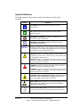
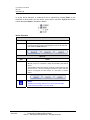
Symbol Definitions
The following table lists those symbols used in this document to denote certain
conditions.
Symbol
Definition
ATTENTION: Identifies information that requires special
consideration.
TIP: Identifies advice or hints for the user, often in terms of
performing a task.
REFERENCE - EXTERNAL: Identifies an additional source of
information outside of the booklet.
REFERENCE - INTERNAL: Identifies an additional source of
information within the booklet.
CAUTION
Indicates a situation which, if not avoided, may result in equipment
or work (data) on the system being damaged or lost, or may result in
the inability to properly operate the process.
CAUTION: Indicates a potentially hazardous situation which, if not
avoided, may result in minor or moderate injury. It may also be used
to alert against unsafe practices.
CAUTION symbol on the equipment refers the user to the product
manual for additional information. The symbol appears next to
required information in the manual.
WARNING: Indicates a potentially hazardous situation, which, if not
avoided, could result in serious injury or death.
WARNING symbol on the equipment refers the user to the product
manual for additional information. The symbol appears next to
required information in the manual.
WARNING - RISK OF ELECTRICAL SHOCK: Indicates a potential
shock hazard where HAZARDOUS LIVE voltages greater than 30
Vrms, 42.4 Vpeak, or 60 VDC may be accessible.
ESD HAZARD: Indicates danger of electro-static discharge to which
equipment may be sensitive. Observe precautions for handling
electrostatic sensitive devices.
Protective Earth (PE) terminal: Provided for connection of the
protective earth (green or green/yellow) supply system conductor.
v
June 2011
TMS Toolkit User Manual
Honeywell Confidential & Proprietary
© 2011 – Honeywell International Inc. All rights reserved
V 1.2.4
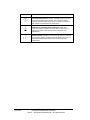
Symbol
Definition
Functional earth terminal: Used for non-safety purposes such as
noise immunity improvement. NOTE: This connection shall be
bonded to Protective Earth at the source of supply in accordance
with national local electrical code requirements.
Earth Ground: Functional earth connection. NOTE: This
connection shall be bonded to Protective Earth at the source of
supply in accordance with national and local electrical code
requirements.
Chassis Ground: Identifies a connection to the chassis or frame of
the equipment shall be bonded to Protective Earth at the source of
supply in accordance with national and local electrical code
requirements.
vi
June 2011
TMS Toolkit User Manual
Honeywell Confidential & Proprietary
© 2011 – Honeywell International Inc. All rights reserved
V 1.2.4
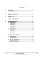
Contents
1.
OVERVIEW ..................................................................................9
1.1
System Requirements .............................................................................9
2.
MODES OF OPERATION ..........................................................11
3.
INSTALLATION .........................................................................13
4.
INITIAL CONFIGURATION ........................................................17
5.
NORMAL USER MODE .............................................................19
5.1
Window Sections....................................................................................19
Communications .................................................................................................. 19
Device Information ...............................................................................................20
Packet Counts...................................................................................................... 21
Traffic...................................................................................................................22
Immediate Window .............................................................................................. 23
Error List .............................................................................................................. 23
5.2
Multi-Dropped TMS ................................................................................23
5.3
Parameters Tab ......................................................................................26
Button Functions .................................................................................................. 28
Test Comms Tab ................................................................................................. 29
System Zero Tab .................................................................................................32
Quality Test Tab................................................................................................... 33
6.
CALIBRATION USER MODE ....................................................35
6.1
ToolKit Shortcut .....................................................................................35
Create a New Shortcut......................................................................................... 35
Edit the New Shortcut .......................................................................................... 36
6.2
CAL User - Parameters Tab...................................................................36
CAL User - Button Functions ............................................................................... 38
6.3
vii
June 2011
Cal User - System Zero Tab ..................................................................39
TMS Toolkit User Manual
Honeywell Confidential & Proprietary
© 2011 – Honeywell International Inc. All rights reserved
V 1.2.4
7.
8.
TROUBLESHOOTING ...............................................................41
7.1
Cannot Communicate ............................................................................41
7.2
Error Messages – “Cannot connect to Local TMS!”...........................41
7.3
Error Messages – “An error occurred while attempting to identify device!”
7.4
Error Messages – “Broadcast ID Information” ...................................43
43
APPENDIX .................................................................................45
8.1
Appendix A – Commands and Parameter Descriptions ....................45
8.2
Appendix B – ASCII XP Protocol ..........................................................50
ASCIIXP Protocol................................................................................................. 50
8.3
Appendix C - Software License ............................................................53
INTRODUCTION ................................................................................................. 53
END-USER LICENSE AGREEMENT FOR TMS TOOLKIT................................. 53
SOFTWARE PRODUCT LICENSE...................................................................... 53
GRANT OF LICENSE. ......................................................................................... 54
DESCRIPTION OF OTHER RIGHTS AND LIMITATIONS. ................................. 54
UPGRADES.........................................................................................................54
COPYRIGHT........................................................................................................ 55
DUAL-MEDIA SOFTWARE. ................................................................................ 55
LIMITED WARRANTY; WARRANTY DISCLAIMER ............................................ 55
viii
June 2011
TMS Toolkit User Manual
Honeywell Confidential & Proprietary
© 2011 – Honeywell International Inc. All rights reserved
V 1.2.4
1. Overview
Rev: A
008-0737-00
1.
Overview
The TMS Toolkit is a software tool that allows communication with the TMS 9250 system.
This software can be used to:
See a list of supported parameters and commands
Read back the values of readable parameters
Write values to writeable parameters
Execute commands
Retrieve a list of readable parameter names and values which can then be copied to a
file
Calibrate the device
Perform simple repetitive communications requests
You would use this software to:
1.1
Test communications with devices
Configure devices
Calibrate devices
System Requirements
Operating system –Windows XP or Windows 7
The screen must support and be set for a resolution of 800 x 600 or higher
NOTE:
Ensure that WinXP users have “write” permissions for the relevant
program files folder (usually \Program Files\TMS Toolkit)
V 1.2.4
June 2011
TMS Toolkit User Manual
Honeywell Confidential & Proprietary
© 2011 – Honeywell International Inc. All rights reserved
9
This page is intentionally left blank.
2. Modes of Operation
Rev: A
008-0737-00
2. Modes of Operation
The TMS Toolkit offers two modes of user access: the “normal” user mode and the
“calibration” (or “cal”) user mode. These modes differ in the level of accessibility to system
functions such as calibration and scaling.
The “normal” user mode is the default mode and in this mode the user can set up
communications with a TMS 9250 system and can also set zero and change filter settings.
The “calibration” user mode requires a special command to gain access and then all
commands and settings become available for edit/recall.
For ease of reference, all of the functions associated with the “calibration” user mode are
arranged at the end of this document. All of the sections at the beginning of this document
apply equally to both user modes.
NOTE:
This dual-mode functionality is intended as a means to reduce the
incidence of unintentional access to key parameters and is not
intended as a high security protection system
V 1.2.4
June 2011
TMS Toolkit User Manual
Honeywell Confidential & Proprietary
© 2011 – Honeywell International Inc. All rights reserved
11
This page is intentionally left blank.
3. Installation
Rev: A
008-0737-00
3. Installation
The TMS Toolkit is supplied on DVD or alternatively, may also be downloaded from the
Honeywell website: http://measurementsensors.honeywell.com. Before installing, be sure
to remove any earlier versions by using the Uninstall programs feature on your computer.
NOTE:
Some earlier versions were named SPM Toolkit.
To install:
V 1.2.4
June 2011
Step
Action
a
Unzip the file 009-4689-00_exec.zip from the DVD and copy the files
onto the hard disk.
b
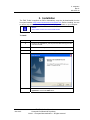
Double-click on Setup.exe.
c
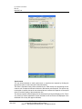
TMS Toolkit Setup Wizard Screen will appear. Click the Next button.
d
Check the radio button “I accept the terms of the license
agreement” and click the Next button.
TMS Toolkit User Manual
Honeywell Confidential & Proprietary
© 2011 – Honeywell International Inc. All rights reserved
13
3. Installation
Rev: A
008-0737-00
14
June 2011
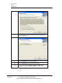
e
Select the folder where the installation files should be copied and
click the Next button.
f
Click the Install button to start the installation.
g
Click the Finish button to complete the installation.
h
Launch the program from Start > Programs > TMS Toolkit.
Desktop short cut icon will also be placed.
TMS Toolkit User Manual
Honeywell Confidential & Proprietary
© 2011 – Honeywell International Inc. All rights reserved
V 1.2.4
3. Installation
Rev: A
008-0737-00
V 1.2.4
June 2011
TMS Toolkit User Manual
Honeywell Confidential & Proprietary
© 2011 – Honeywell International Inc. All rights reserved
15
This page is intentionally left blank.
4. Initial Configuration
Rev: A
008-0737-00
4. Initial Configuration
To test the serial port setting and the TMS 9250 itself, connect the TMS 9250 to one of the
PCs serial ports. If using a PC which does not have a RS232 serial port, then a high quality
USB-to-RS232 converter may be used instead. (For example, Uport 1150 from Moxa http://www.moxa.com/product/UPort_1150_1150I.htm )
NOTE:
Such converters may have limitations such as the use of short cable
lengths or special cable types to ensure reliable communications at
38400 baud. If in doubt, use a PC that has a true RS232 serial port
built in to confirm communications, then try a laptop afterwards.
This example will assume that there is only one TMS 9250 connected to the serial bus. See
the Multi-Dropped TMS section on page 23 of this manual for more information when using
more than one TMS 9250 system on the same serial bus.
V 1.2.4
June 2011
TMS Toolkit User Manual
Honeywell Confidential & Proprietary
© 2011 – Honeywell International Inc. All rights reserved
17
4. Initial Configuration
Rev: A
008-0737-00
Step
18
June 2011
Action
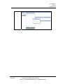
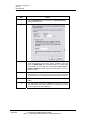
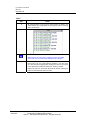
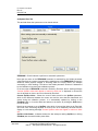
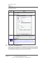
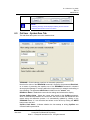
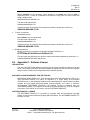
a
Click the SETTINGS button. This will open the Comms Settings
dialog window as shown.
b
Select the SERIAL PORT that the TMS is connected to (can be
found from Windows Control Panel, System, Hardware, Ports) and
select the BAUD RATE. The default Baud Rate for standard TMS
9250 systems can be found from the Windows Control Panel >
System > Hardware > Ports. Select the BAUD RATE as shown in
the above image.
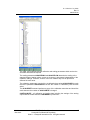
c
Ensure that the TMS ID field is left blank unless there are multiple
TMS 9250 devices connected to the same serial bus, in which case
the ID must be set to correspond with the ID of the device of interest.
d
Click OK when changes have been made, then click the CONNECT
button.
e
The TMS Toolkit searches the designated serial port to find the
connected device. The software takes care of configuring the port to
suit the requirements of the TMS 9250.
TMS Toolkit User Manual
Honeywell Confidential & Proprietary
© 2011 – Honeywell International Inc. All rights reserved
V 1.2.4
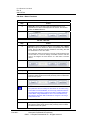
5. Normal User Mode
Rev: A
008-0737-00
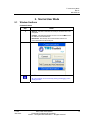
5. Normal User Mode
5.1
Window Sections
Communications
Step
a
Action
Settings - This button will allow the serial port and baud rate to be
configured.
Connect - This will automatically connect to the local TMS device if
the TMS ID can be determined.
Disconnect - This will stop the communication between the
connected device and the serial port.
NOTE:
All of the windows can be re-sized by clicking and dragging on the
dividing borders.
V 1.2.4
June 2011
TMS Toolkit User Manual
Honeywell Confidential & Proprietary
© 2011 – Honeywell International Inc. All rights reserved
19
5. Normal User Mode
Rev: A
008-0737-00
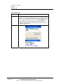
Device Information
Step
Action
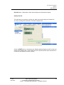
a
After successfully connecting, the Toolkit will display the serial
number of the connected system along with the model, software
version, and default parameter name. The default parameter is the
one that will be selected for display on the TEST COMMS tab until
over-ridden by a selection from the drop-down parameter table.
Clicking the button on the header will copy the information to the
clipboard as shown below.
20
June 2011
TMS Toolkit User Manual
Honeywell Confidential & Proprietary
© 2011 – Honeywell International Inc. All rights reserved
V 1.2.4
5. Normal User Mode
Rev: A
008-0737-00
Packet Counts
V 1.2.4
June 2011
Step
Action
a
Each time the software communicates with the remote device, the
Packet Counts section is updated. This lists the number of packets
sent out and received, and also indicates the number of packets
received per second and the number of errors that have occurred.
When an error occurs, details are given in the ERROR LIST.
b
Clicking the button on the header will reset the counts.
TMS Toolkit User Manual
Honeywell Confidential & Proprietary
© 2011 – Honeywell International Inc. All rights reserved
21
5. Normal User Mode
Rev: A
008-0737-00
Traffic
Step
Action
a
All communications to and from the remote device are listed in the
Traffic window. The outgoing data is colored green and the incoming
data is colored blue.
NOTE:
When packets are retried, this is a hidden function of the TMS
device and only one packet will be displayed in this window.
b
This is very useful for inspecting the construction of data packets
when writing your own communications software. It can also serve
as a short-term data logging facility because the data can be copied
to the clipboard and pasted into Microsoft® Excel for analysis.
Clicking the button on the header will clear the window. Clicking the
button on the header will reset the counts.
22
June 2011
TMS Toolkit User Manual
Honeywell Confidential & Proprietary
© 2011 – Honeywell International Inc. All rights reserved
V 1.2.4
5. Normal User Mode
Rev: A
008-0737-00
Immediate Window
Step
Action
a
Type the data directly into the window (you will not need to use any
special addressing or special characters), then press the
enter/return key. The list of valid commands/queries can be found in
Appendix A of this manual.
If the device responds, the data will be displayed in blue and any
errors will be indicated in red.
Example: To query the current torque value, enter
VALUE?
To set the current torque value to zero, enter ZERONOW
b
Clicking the button on the header will clear the window.
Error List
Step
a
b
5.2
Action
Any errors that are encountered when sending commands or
queries, and errors in communications such as timeouts etc will be
reported in the Error List in red
Clicking the button on the header will clear the window.
Multi-Dropped TMS
Multiple TMS 9250 devices can be connected to the same serial bus and port when that
port is either an RS485 port or has an RS232 to RS485 converter attached.
When more than one TMS 9250 is present, the auto detection of TMS ID will not work. It is
necessary to declare the ID of the TMS 9250 device that the communication is intended to
be routed to that particular device.
This is done in the COMMS SETTINGS window by entering the ID of the TMS 9250 system
(in the form XXXXXX) in the field labeled TMS ID.
Step
V 1.2.4
June 2011
Action
TMS Toolkit User Manual
Honeywell Confidential & Proprietary
© 2011 – Honeywell International Inc. All rights reserved
23
5. Normal User Mode
Rev: A
008-0737-00
a
Settings - This button will allow the serial port and baud rate to be
configured.
Connect - This will automatically connect to the local TMS device if
the TMS ID can be determined.
Disconnect – This will stop the communication between the
connected device and the serial port.
NOTE:
All of the windows can be re-sized by clicking and dragging on the
dividing borders.
24
June 2011
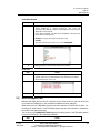
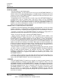
b
Click the SETTINGS button. This will open the COMMS SETTINGS
dialog window as shown.
c
Select the SERIAL PORT that the TMS is connected to (which can
be found from the Windows Control Panel / System / Hardware /
Ports) and select the BAUD RATE as pictured above. The default
TMS Toolkit User Manual
Honeywell Confidential & Proprietary
© 2011 – Honeywell International Inc. All rights reserved
V 1.2.4
5. Normal User Mode
Rev: A
008-0737-00
BAUD RATE for standard TMS 9250 systems is 38400 (nonstandard systems will be delivered with appropriate special
instructions).
V 1.2.4
June 2011
d
Enter the TMS ID (printed on the yellow label attached to the
motherboard inside the signal processing module) in the form
FFFFFF, to correspond with the ID of the device of interest.
e
Click the OK button when changes have been made, then click the
CONNECT button.
f
The TMS Toolkit searches the designated serial port to find the
connected device. The software takes care of configuring the port to
suit the requirements of the TMS 9250.
TMS Toolkit User Manual
Honeywell Confidential & Proprietary
© 2011 – Honeywell International Inc. All rights reserved
25
5. Normal User Mode
Rev: A
008-0737-00
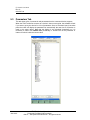
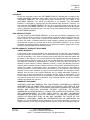
5.3
Parameters Tab
This tab shows a list of commands and parameters that the connected device supports.
When the TMS Toolkit first connects to a device it does not recognize, the software will ask
if you want to query the device for a list of parameters. Once a successful query has taken
place the toolkit will display the parameter list automatically the next time a connection is
made to the same device. Note that the display is not refreshed dynamically so it is
necessary to either click QUERY ALL periodically or double-click on the parameter of
interest to refresh it with the current value.
26
June 2011
TMS Toolkit User Manual
Honeywell Confidential & Proprietary
© 2011 – Honeywell International Inc. All rights reserved
V 1.2.4
5. Normal User Mode
Rev: A
008-0737-00
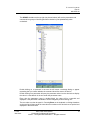
The GROUP checkbox at the top right (as pictured above) will sort the parameters and
commands into groups of similar types when checked or just alphabetically when
unchecked.
Double-clicking on a command in the tree list will cause a message dialog to appear
requesting that you confirm whether the command should be sent to the device.
Double-clicking on a parameter will query the parameter value from the device then display
the value in a new branch in the tree under the parameter name.
Every time the parameter name is double-clicked, the value will be re-queried and
displayed. If the parameter is writeable it can be changed by double-clicking on it.
The new value can then be typed in. Pressing Enter on the keyboard or clicking elsewhere
on the tree list will then cause the new value to be written to the device then re-queried and
displayed in the tree branch.
V 1.2.4
June 2011
TMS Toolkit User Manual
Honeywell Confidential & Proprietary
© 2011 – Honeywell International Inc. All rights reserved
27
5. Normal User Mode
Rev: A
008-0737-00
In all the above directions, a double-click can be replaced by pressing Enter on the
keyboard. In other words, you can use the cursor keys to move the highlight around the
tree list then press Enter to activate the branch.
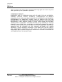
Button Functions
Query All
Step
a
Action
Query All - Clicking this button will cause the available parameters
to be queried from the device and displayed in the tree list. This will
also enable the Save List button.
Save List
Step
Action
a
Save List - Clicking this button, which is only available after a Query
All, will prompt for a filename to which the parameter data will be
saved.
The parameter values are saved to a text file (.ttp file extension) and
can be used as a record of settings used within a device and also
used to re-configure the same device at a later date or another
device.
NOTE:
Calibration and scaling data will not be saved unless the TMS
Toolkit is being operated in “Cal” user mode.
28
June 2011
TMS Toolkit User Manual
Honeywell Confidential & Proprietary
© 2011 – Honeywell International Inc. All rights reserved
V 1.2.4
5. Normal User Mode
Rev: A
008-0737-00
Load List
Step
Action
a
Load List - Clicking this button will prompt for a filename (.ttp file
extension) which will be used to load previously saved or edited data
back into the system.
NOTE:
Calibration and scaling data will not be loaded unless the TMS
Toolkit is being operated in “Cal” user mode.
Also note, the parameter files are actually text files which can be
edited, using a text editor such as NOTEPAD, to remove any
parameters that are not required to be written to a device and also to
modify parameter values. When using NOTEPAD, be sure to save
the file with a .ttp file extension otherwise TMS Toolkit will not
recognize it as being a valid parameter file.
Test Comms Tab
This tab allows simple repetitive communications to be established. You can select a
readable parameter from the Select Parameter to Request dropdown list and an update
rate from the Select Request Rate dropdown list.
Note that you can also type directly into the Select Parameter to Request dropdown list
and the color of the list will change to red indicating that the parameter to be requested is
currently being changed. The communications will continue to request the previous
parameter until either the Return/Enter key is pressed on the keyboard or focus moves to
another control.
V 1.2.4
June 2011
TMS Toolkit User Manual
Honeywell Confidential & Proprietary
© 2011 – Honeywell International Inc. All rights reserved
29
5. Normal User Mode
Rev: A
008-0737-00
Synchronous
You can choose whether to send synchronous or asynchronous requests by clicking the
appropriate option on the lower part of the task window.
The data is requested using retries (handled by the TMS device) and processing will not
continue until a response has been received or the timeout period expires. This option may
not be able to request data at the rate selected above, because this depends on the speed
of the PC and the quality of the transmission line.
The device response will be displayed in the simulated Liquid Crystal Display (LCD). This is
only useful for numeric parameters (some characters such as M cannot be displayed in the
simulated LCD so they will appear as blanks).
30
June 2011
TMS Toolkit User Manual
Honeywell Confidential & Proprietary
© 2011 – Honeywell International Inc. All rights reserved
V 1.2.4
5. Normal User Mode
Rev: A
008-0737-00
The required number of decimal places to display can be selected from the dropdown list
next to the LCD.
Below the main LCD there is a smaller LCD (the DELTA window) which displays the
change in the main reading LCD since the last reset. This display can be reset as required
by clicking the Reset button.
Asynchronous
The data is requested just once. There are no retries and no errors are reported if there is
no response. If and when the response packet arrives, the packed ID (PID) is inspected
and if it matches the PID in the request, the data will be displayed in the LCD. Processing
continues while the data is being waited for. In this mode the 'Received On' label will
indicate the date and time that the packet arrived. This option will usually appear to run
faster than the synchronous option because it is not necessary to wait for a response
before sending the next command. However, the data collected may contain gaps.
V 1.2.4
June 2011
TMS Toolkit User Manual
Honeywell Confidential & Proprietary
© 2011 – Honeywell International Inc. All rights reserved
31
5. Normal User Mode
Rev: A
008-0737-00
sssSystem Zero Tab
This task tab allows the system zero to be viewed and set.
ZERONOW - Click this button to perform an automatic system zero.
Note that the action of the ZERONOW command is restricted by the hidden parameter
called ZeroLimit as a means of preventing the repetitive use of the ZERONOW command in
situations where physical damage is occurring within the torque sensor (for example
overloading or shock loading). The value of the hidden parameter ZeroLimit is determined
by the Calibration User during the calibration process.
In the event that a ZERONOW command is limited by ZeroLimit, then a warning message
“Current SySZero value was clipped to conform to limits set” is displayed in red and the
zero is adjusted as close to zero as is allowed by ZeroLimit.
Current SysZero Value - Shows the current value stored for the SysZero parameter,
which is the difference between the current zero and the zero that was determined and
stored during the calibration process. It is automatically updated by clicking on the
ZeroNow button or it can be edited and written to the device by clicking the Write button
next to the field.
Note that any attempt to set a SysZero value which is beyond the limits set by ZeroLimit
will result in the zero being adjusted as close to zero as is allowed by ZeroLimit and the
display of a red warning message “Current SysZero value was clipped to conform to limits
set”.
SysZero Limit Status - Indicates whether the last attempt at writing SysZero (or clicking
ZeroNow) was successful within preset limits.
32
June 2011
TMS Toolkit User Manual
Honeywell Confidential & Proprietary
© 2011 – Honeywell International Inc. All rights reserved
V 1.2.4
5. Normal User Mode
Rev: A
008-0737-00
Read All button - Reads back current device settings and refreshes the display.
Quality Test Tab
This tab allows you to perform a quality test, which checks the integrity of the electronic
circuits by sending shunt calibration commands multiple times.
Click the START button to activate the test. Reading window displays raw A-D counts and
Quality Value displays the % result. When the test is performed final value should be 97%
or above for the system to function correctly.
V 1.2.4
June 2011
TMS Toolkit User Manual
Honeywell Confidential & Proprietary
© 2011 – Honeywell International Inc. All rights reserved
33
This page is intentionally left blank.
6. Calibration User Mode
Rev: A
008-0737-00
6. Calibration User Mode
6.1
ToolKit Shortcut
To access the higher-level functions such as calibration and scaling settings, it is
necessary to start the TMS Toolkit in “Cal” mode.
Create a New Shortcut
V 1.2.4
June 2011
Step
Action
a
Create a copy of the TMS Toolkit shortcut on the desktop (such as
by using the control-click-drag-drop sequence or by clicking the right
mouse button to choose the Copy then Paste command).
b
Right-click on the new shortcut and rename it to represent the
“Calibration” user mode.
c
Right-click on the new shortcut and select PROPERTIES.
TMS Toolkit User Manual
Honeywell Confidential & Proprietary
© 2011 – Honeywell International Inc. All rights reserved
35
6. Calibration User Mode
Rev: A
008-0737-00
Edit the New Shortcut
Step
Action
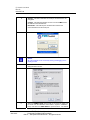
a
Edit the TARGET line by adding /cal after the quote marks (note – a
space is required between the quote mark and the /cal text), as
pictured below.
b
Click the OK button and then test that the modified shortcut calls up
the CALIBRATION mode of the TMS Toolkit. The header line which
previously showed TMS Toolkit should now show TMS Toolkit –
CALIBRATION.
NOTE:
If the header line continues to show TMS Toolkit then close TMS
Toolkit and return to the shortcut properties dialogue box. Check that
the space exists between the quote marks (”) and the forward slant
character (/).
6.2
CAL User - Parameters Tab
This tab now shows a complete list of commands and parameters that the connected
device supports. The parameters that are “reserved” for “Cal” user access are prefixed
with the # character. Security Note - the # commands and parameters can be entered via
the Immediate Window regardless of the mode of use of TMS Toolkit.
36
June 2011
TMS Toolkit User Manual
Honeywell Confidential & Proprietary
© 2011 – Honeywell International Inc. All rights reserved
V 1.2.4
6. Calibration User Mode
Rev: A
008-0737-00
The “Cal” user mode exposes the calibration and scaling parameters which can then be
accessed and edited as required.
The scaling parameters #ANOUTHIGH and #ANOUTLOW determine the scaling of the
standard outputs (analog voltage, current or frequency), and operate independently of the
calibration settings. Therefore, a sensor can be re-scaled at any time to represent a
different full scale value.
The calibration parameters consist of the 9 calibration data values #CALVALUE1 through
9 and the parameter #CALPOINTS that sets the number of calibration points that are
active.
The #CALRESET command performs a purge of the calibration memories and should be
used whenever the number of #CALPOINTS is changed.
CAUTION NOTE – all calibration and scaling data including the settings of the analog
outputs will be erased whenever #CALRESET is performed.
V 1.2.4
June 2011
TMS Toolkit User Manual
Honeywell Confidential & Proprietary
© 2011 – Honeywell International Inc. All rights reserved
37
6. Calibration User Mode
Rev: A
008-0737-00
CAL User - Button Functions
Cal user - Query All
Step
a
Action
Query All - Clicking this button will cause all parameters to be
queried from the device and displayed in the tree list. This will also
enable the Save List button.
Cal user - Save List
Step
Action
a
Save List - Clicking this button, which is only available after a Query
All, will prompt for a filename to which the parameter data will be
saved. Note that all data including calibration and scaling data will
be saved when in “Cal” user mode.
The parameter values are saved to a text file (.ttp file extension) and
can be used as a record of settings used within a device and also
used to re-configure the same device at a later date or another
device.
Cal user - Load List
Step
Action
a
Load List - Clicking this button will prompt for a filename (.ttp file
extension) which will be used to load previously saved or edited data
back into the system.
NOTE:
The parameter files are actually text files which can be edited, using
a text editor such as NOTEPAD, to remove any parameters that are
not required to be written to a device and also to modify parameter
values. When using NOTEPAD, be sure to save the file with a .ttp
file extension otherwise TMS Toolkit will not recognize it as being a
valid parameter file.
Cal user - Load Cal Only
Load Cal Only - Clicking this button will prompt for a filename (.ttp
file extension) which will be used to load previously saved or edited
Cal data back into the system.
38
June 2011
TMS Toolkit User Manual
Honeywell Confidential & Proprietary
© 2011 – Honeywell International Inc. All rights reserved
V 1.2.4
6. Calibration User Mode
Rev: A
008-0737-00
NOTE:
A warning message will be displayed advising the user that the
calibration data is about to be over-written.
6.3
Cal User - System Zero Tab
This tab allows the system zero to be viewed and set.
ZERONOW - Click this button to perform an automatic system zero.
Note that the action of the ZERONOW command is limited by the parameter #ZeroLimit,
as a means of preventing the repetitive use of the ZERONOW command in situations
where physical damage is occurring within the torque sensor (for example overloading or
shock loading). The parameter #ZeroLimit is hidden from the “normal” user.
READ ALL Button - Reads back current device settings and refreshes the display.
Current SysZero Value - Shows the current value stored for the SysZero parameter,
which is the difference between the current zero and the zero that was determined and
stored during the calibration process. It is automatically updated by clicking on the
ZERONOW button or it can be edited and written to the device by clicking the WRITE
button next to the field.
SysZero Limit Status - Indicates whether the last attempt at writing SysZero was
successful within preset limits.
V 1.2.4
June 2011
TMS Toolkit User Manual
Honeywell Confidential & Proprietary
© 2011 – Honeywell International Inc. All rights reserved
39
6. Calibration User Mode
Rev: A
008-0737-00
In the event that a Zero Now or a SysZero value is limited by #ZeroLimit, then a warning
message “Current SySZero value was clipped to conform to limits set” is displayed in red
and the zero is adjusted as close to zero as is allowed by #ZeroLimit.
#ZeroLimit - Shows the limits (+ and - ) within which the current value is allowed to be set
to zero. This limit can be edited and written to the device by clicking the Write button next
to the numeric field. The limit is set in engineering units (the same as the calibration units)
and is used as a way of preventing repetitive use of the ZeroNow command in cases
where physical damage may be occurring within the torque sensor (for example
overloading or shock loading).
The factory setting for this parameter is 50% of the value used for the analog output
(#ANOUTHIGH) of the sensor and there is no test for polarity so the limit will apply either
side of the “true” zero that was automatically determined by the system during the
calibration process. The user may wish to set tighter limits after installing and exercising
the sensor.
NOTE:
#ZeroLimit is only displayed when operating TMS Toolkit at the
“Cal” user access level.
40
June 2011
TMS Toolkit User Manual
Honeywell Confidential & Proprietary
© 2011 – Honeywell International Inc. All rights reserved
V 1.2.4
7. Troubleshooting
Rev: A
008-0737-00
7. Troubleshooting
7.1
Cannot Communicate
Check all wiring
If using the RS232 port, check that the Rx pin of the host computer is connected to the Tx pin of
the TMS 9250 and vice versa
Check that the communications cable being used is of high quality or try a shorter length of
cable (RS232 is sensitive to cable length and grounding issues, especially when used with
laptop computers where grounding is uncertain)
Check that the correct serial port is selected in the software or TMS Toolkit. When using
Windows, the serial port in use can be found by using the CONTROL PANEL > SYSTEM >
HARDWARE > DEVICE MANAGER > COM ports functions
On older desktop PCs, the COM1 port is already in use for the mouse, so a different COM port
should be selected
If using a USB to Serial adapter, Windows assigns the COM port designations dynamically so
they may change whenever the system is rebooted
The serial port settings are automatically modified by TMS Toolkit so there is no need to
change any of the settings in Windows
The baud rate setting in TMS Toolkit should always be 38400 because that is the default baud
rate of the TMS 9250
The “TMS ID” should be left blank because TMS Toolkit will search the connected port for any
TMS device and will commence the communication automatically if present
NOTE:
Do not attempt to change baud to any non-standard values.
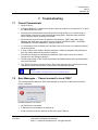
7.2
Error Messages – “Cannot connect to Local TMS!”
This message appears whenever TMS Toolkit attempts to connect to a TMS device and fails to
receive a response.
Possible reasons are as follows:
No TMS device is connected
A TMS device is connected but is powered off
A bad or broken connection exists at the PC end or at the TMS end
V 1.2.4
June 2011
TMS Toolkit User Manual
Honeywell Confidential & Proprietary
© 2011 – Honeywell International Inc. All rights reserved
41
7. Troubleshooting
Rev: A
008-0737-00
The TMS device is connected to the wrong communications port at the PC end (should be the
same as was selected on the Settings tab) or at the TMS end (should be J7)
If trying to connect for the first time, the connections may be incorrect (RS232 requires a
crossover between devices, so Rx should connect to Tx and vice versa)
Check all of the above and try again
42
June 2011
TMS Toolkit User Manual
Honeywell Confidential & Proprietary
© 2011 – Honeywell International Inc. All rights reserved
V 1.2.4
7. Troubleshooting
Rev: A
008-0737-00
7.3 Error Messages – “An error occurred while attempting to identify
device!”
This message appears whenever TMS Toolkit attempts to connect to a TMS device and receives
an unexpected or invalid response.
Possible reasons are as follows:
7.4
The connected device is not a TMS
The connection between the PC and the TMS is too long for reliable RS232 communications
Check all of the above and try again
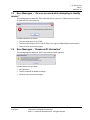
Error Messages – “Broadcast ID Information”
This message appears whenever TMS Toolkit sends an XXXX response.
Possible reasons are as follows:
No TMS device
TMS ID is entered as 000000 in settings
Check all of the above and try again
V 1.2.4
June 2011
TMS Toolkit User Manual
Honeywell Confidential & Proprietary
© 2011 – Honeywell International Inc. All rights reserved
43
This page is intentionally left blank.
8. Appendix
Rev: A
008-0737-00
8. Appendix
8.1
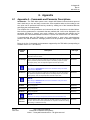
Appendix A – Commands and Parameter Descriptions
Introduction - The TMS 9250 system uses a simple ASCII-based communications protocol
that is both easy to use and easy to memorize. Some repetitive tasks such as setting a new
zero point can be performed with less key strokes by making use of the Immediate Window
and keying the command directly.
The complete list of valid parameters and commands and their functions are included below.
Note that any parameters or commands that are prefixed with # will not be displayed in the
parameter list when in “normal” user mode. However, all commands and settings can be
accessed via the Immediate Window in either the “normal” user mode or the “Cal” user mode.
If communicating with the TMS 9250 via HyperTerminal or some other communications
channel, then the full ASCII-XP message protocol must be provided, as detailed in Appendix
B.
Below is the list of commands and parameters supported by the TMS 9250 (corresponding to
software version v1.2.1 and above).
Description
Parameter
Name
Data Type
#A
Mode reporting access used by TMS Toolkit software to extract parameter
information from the device.
Read only
#AnOutHigh
Sets or returns the value in engineering units applied to the input that will give
100% (maximum positive full scale) output on the analog outputs. To invert
the output polarity, enter the required negative full scale output value.
Read/write
NOTE:
Any change to #AnOutHigh will result in the cancellation of any zero offset
value stored in #SysZero.
#AnOutLow
Sets or returns the value in engineering units applied to the input that will give
0% (minimum negative full scale) output on the analog outputs. To invert the
output polarity, enter the required positive full scale output value.
Read/write
NOTE:
Any change to #AnOutLow will result in the cancellation of any zero offset
value stored in #SysZero.
AuxBaud
Not yet supported.
Read/write
AuxOPType
Not yet supported.
Read/write
BaudRate
Not yet supported.
Read only
NOTE:
Please do not attempt to change this parameter from the Parameters tab.
*CalCnts1*CalCnts9
V 1.2.4
June 2011
Internal calibration data. This is read only via TMS Toolkit and is viewable only
in “CAL” level access. These parameters are exposed to enable the saving
and loading of calibration data only.
TMS Toolkit User Manual
Honeywell Confidential & Proprietary
© 2011 – Honeywell International Inc. All rights reserved
Read only
45
8. Appendix
Rev: A
008-0737-00
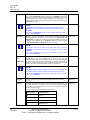
#CalPoints
Sets the number of calibration points in use. Value must be between 2 and 9.
Any change in #CalPoints should be followed by a #CalReset command to
clear the previous unwanted calibration data from the memories. For correct
system operation, the number of active calibration values (#CalValue 1~9)
must be equal to the number of calibration points that are defined by the
#CalPoints parameter.
Read/write
NOTE:
All calibration data and all analog output setting data will be cleared by
#CalReset. It is recommended to save the parameter list before invoking
#CalReset.
Any change to #AnOutHigh will result in the cancellation of any zero offset
value stored in #SysZero.
#CalReset
Resets all calibration information. When the reset command is issued, all
calibration data and all settings of the analog outputs (#AnOutHigh and
#AnOutLow) are cleared so no reliable output will be available until all of the
calibration points specified by the #CalPoints parameter and the required
values of #AnOutHigh and #AnOutLow have been entered.
Command
NOTE:
All calibration data and all analog output setting data will be cleared by
#CalReset. It is recommended to save the parameter list before invoking
#CalReset.
Any change to #AnOutHigh will result in the cancellation of any zero offset
value stored in #SysZero.
#CalValue1
to
#CalValue9
These values are written in engineering units when the appropriate load is
applied. Each of the nine parameters can be written at any time. See
Calibration section later in this document. NOTE – the values entered MUST
be in ascending order, starting with #CalValue1 (negative values count as
lower than positive values). The number of calibration points entered must be
equal to the number of calibration points activated by #CalPoints.
Read/write
NOTE:
The existing calibration data is overwritten by any new input of #CalValue1~9.
It is recommended to save the parameter list before entering new values.
Any change to #CalValue1~9 will result in the cancellation of any zero offset
value stored in #SysZero.
#Counts
Returns the raw A-D counts value derived from the ADC on the rotating
sensor.
Read only
ErrFlag
The ErrFlag parameter will indicate any errors that have occurred by returning
a numeric value that is comprised of binary values representing the various
error states. i.e. the binary values for each error are added together to
produce the ErrFlag value.
Read only
The error states are not retained between power cycles.
46
June 2011
Decimal Value
Error Description
0
No error.
1
Power cycled.
2
Output clamped.
4
Watchdog reset.
TMS Toolkit User Manual
Honeywell Confidential & Proprietary
© 2011 – Honeywell International Inc. All rights reserved
V 1.2.4
8. Appendix
Rev: A
008-0737-00
Once the errors have been read they can be reset using the RstErrFlag
command.
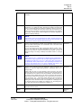
#FastMode
Used to initiate raw throughput of data without scaling or filtering. Set this
parameter to 1 to enable fast mode. This setting is volatile so the device will
revert to normal mode after the next Reset command or after the next powerup. Set to zero to disable fast mode. When in fast mode, the internal raw A-D
counts results are fed directly to the analog output (voltage or current) without
any scaling or filtering, giving a data throughput rate of 8.8 kHz (regardless of
FiltLevel or FiltSteps settings).
Read/write
NOTE:
The frequency output is not supported in fast mode. The fast mode can be
scaled in the user’s data acquisition system by using the shunt cal facility, and
is intended to be used for dynamic measurements only.
FiltLevel
Used to set the threshold of operation of the digital filter. Values are set as
parts per 10000, meaning that to set a threshold of 10% of the sensor rated
capacity, then FiltLevel=1000.
Read/write
For a % step change in input which is greater than (FiltLevel / 10000 * 100%),
the new input value will be passed immediately to the output. For a step
change in input which is below the threshold set by FiltLevel, the output is
filtered according to the setting of FiltSteps. Permissible values are 1 through
10000.
NOTE:
When FiltLevel is set to 1, digital filtering is disabled and the unfiltered data is
passed to the analog outputs at a rate of 2.2 kHz. When FiltLevel is set to 2,
the digital filter update rate is set to be 1.1 kHz and the filter characteristic is
set by FiltSteps. Factory default value is 100, representing a threshold of 1%
of sensor rated capacity (refer to the factory calibration data sheet or the
rating plate attached to the sensor to confirm the rated capacity).
FiltSteps
Used to set the response time of the digital filter. Used in conjunction with
FiltLevel to control the digital filtering behavior. Permissible values are 1
through 10000.
Read/write
Filtering takes the form of an RC equivalent, where a change in input value
which is greater than the threshold set by FiltLevel causes the output value to
be incremented in the number of steps set by FiltSteps. The filter refresh rate
is 1100 Hz. Factory default setting is 10, which in conjunction with the factory
default setting of FiltLevel=100 provides for an output increment in the form of
(x/2, x/3, x/4, x/5, x/6 …. x/10) where x=step change in input of more than
((FiltLevel/10000)*rated capacity). Given the filter update rate of 1100 Hz, the
settling time to 63% final value will be 9 ms (Update rate x FiltSteps) and to
1% final value will be 45 ms (Update rate x FiltSteps x 5). The settling time to
0.1% final value will be 64 ms (Update rate x FiltSteps x 7).
#M
Mode reporting access used by TMS Toolkit software to extract parameter
information from the device.
Read only
Model
Returns the model name (TMS)
Read only
string
V 1.2.4
June 2011
TMS Toolkit User Manual
Honeywell Confidential & Proprietary
© 2011 – Honeywell International Inc. All rights reserved
47
8. Appendix
Rev: A
008-0737-00
Sets or returns the currently selected analog output where 0=current;
1=voltage; 2=frequency 10 kHz; 3=frequency 60 kHz, 4=current and
frequency 10 kHz, 5=voltage and frequency 10 kHz, 6=current and frequency
60 kHz, 7=voltage and frequency 60 kHz.
OpType
Read/write
NOTE:
Data throughput performance can be affected by using multiple outputs. For
high speed dynamic data analysis applications (>500Hz), select the voltage
output (OpType=1).
ParaCnt
Returns the number of parameters in the device.
Read
ParaItem
Set to the index number of the required parameter.
Write
ParaList
Returns the information on the parameter
Format: 'index,paraname,type’ a string.
indexed
by
ParaItem.
Read string
The value of type indicates the parameter’s properties by the addition of the
following numerical values:
1
Readable
2
Writeable
4
Command
32
String
64
Numeric
128
Boolean
Example: ‘1,MODEL,33’
In the above example where type = 33. This means the parameter MODEL is a
readable string, i.e. 1 + 32 = 33.
Example: ‘3,UNITS,35’
In the above example where type = 35. This means the parameter UNITS is a
read/writeable string. i.e. 1+2 + 32 = 35.
Percent
Returns the value of the applied torque in percentage terms (0-100) where this
range is the selected range over which the analog outputs work and is set by
#AnOutLow and #AnOutHigh.
Read only
#ReScale
Internal system command, for factory use only.
Command
Reset
Reset command to restart device and to implement parameter changes that
require a reset.
Command
RstErrFlag
Reset all error flags.
Command
#ScScale
Scaling factor applied to the Shunt Calibration value. Can be used to force the
shunt calibration value to any desired value. A setting of 1 causes the shunt
calibration value to be delivered at its raw level, which could be any value
(refer to calibration data sheet for the relevant sensor for the actual value), but
is generally set during manufacture to be between 50% and 99% of the
sensor capacity.
Read/Write
48
June 2011
TMS Toolkit User Manual
Honeywell Confidential & Proprietary
© 2011 – Honeywell International Inc. All rights reserved
V 1.2.4
8. Appendix
Rev: A
008-0737-00
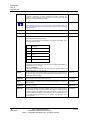
SysZero
Allows manual setting of the current Value or querying of the current zero
offset being applied. The returned value is the amount of zero offset being
applied to the true Value. To zero the system, this parameter should be set in
engineering units to the value read when the system is supposed to be
displaying zero. The action of SysZero may be limited by #ZeroLimit as
described above, in which case the flag ZeroOK will be set to 0. Note that
when any calibration parameter (#CalValue1~9, #CalReset) is changed, the
value of SysZero is set to 0 and any zero offset is cancelled. This function,
when used with #ZeroLimit, allows the current Value to be offset to any
desired level (remember to consider the dynamic loading range of the sensor
itself when applying large offsets).
Read/write
Units
Text memo field in which the name of the engineering units used for
calibration can be stored for recall later. Note that when reading some
characters via a 7-segment display (TMS Toolkit uses a virtual 7-segment
display), some characters such as M will not display correctly.
Read/Write
Usr1~9
Free format, text memo fields for general purpose. Example is the storage of
calibration data and place information, the name of the calibration technician,
etc. Allowable characters are alphanumeric only.
Read/Write
Value
Returns the value of the applied torque in calibrated engineering units.
Read only
Version
Returns the software version.
Read only
ZeroNow
Sets the current value to zero unless limited by #ZeroLimit as described
above. The action performed by ZeroNow is to clear any previous zero offset
then compare the true value to #ZeroLimit, then, to the extent allowable by
#ZeroLimit, write the true Value to SysZero, resulting in a new current value of
zero.
Command
ZeroOK
Returns indication of 1 if the previous ZeroNow command was successful in
setting the current Value to zero and returns 0 if the action was limited by
#ZeroLimit.
Read only
#ZeroLimit
The limit in engineering units at which the ZeroNow command will be allowed
to operate, relative to the computed Value at zero load that was stored during
the calibration process. Therefore #ZeroLimit represents the maximum
allowable difference between the “calibration” zero and the “current” zero. If
the ZeroNow command is issued when the current Value is greater than
#ZeroLimit, then the current Value will be moved to the extent allowed by
#ZeroLimit and the flag ZeroOK will be set to 0. Factory setting is 50% of the
calibrated range. Note that #ZeroLimit is a bipolar setting, so it will be applied
to both directions (+ and -) around the calibration zero value.
Read/Write
*ZeroPVal
Internal system zero data. This is read only via TMS Toolkit and is viewable
only in “CAL” level access. This parameter is exposed to enable the saving
and loading of calibration and zero data.
Read only
V 1.2.4
June 2011
TMS Toolkit User Manual
Honeywell Confidential & Proprietary
© 2011 – Honeywell International Inc. All rights reserved
49
8. Appendix
Rev: A
008-0737-00
8.2
Appendix B – ASCII XP Protocol
Introduction - Communications with the TMS 9250 is carried out using a protocol, ASCIIXP
(ASCII eXtended Protocol), which has been developed for multi-drop telemetry products.
Each TMS 9250 device has a unique device ID that must be used for all communications. The
ID is fixed at production and is referred to in hexadecimal format. The range covered is from
000001 to FFFFFF which gives an address range of 1 to 16777215 decimal. With 16 million
addresses it can be guaranteed that no two devices will have the same ID.
Device ID 000000 is reserved as a ‘Broadcast’ ID. Data transmitted to this ID will be acted on
by all receiving devices. However, devices will not respond with data to a broadcast command.
All devices communicate using the ASCIIXP protocol, which has been designed to be humanly
readable. Another advantage of this protocol is that with its optional parameter structure, it can
just as easily be used from a simple serial terminal program such as HyperTerminal (typed
manually in real-time) as well as a high level device such as a PC or PLC. A driver is available
for use with any programming system that can utilize OCXs. Source code, written in Visual
Basic, is also available.
ASCIIXP Protocol
ASCIIXP is an ASCII protocol designed to be routable over radio, Ethernet or serial links and is
easily programmed and parsed (split into sections). Only ASCII characters are used and the
suffix ‘Carriage Return’ (ASCII value 13, hexadecimal value 0xD) is used as the framing
character. This enables ASCIIXP to be used with common serial terminal applications such as
HyperTerminal. The ‘Enter/Return key’ on a standard keyboard is used to write the framing
character. In the following document <13> will be used to represent the ASCII character 13.
NOTE:
A checksum can be included for integrity but it is optional. If a checksum exists in a received data packet
then a checksum will be included in the returned packet.
The full syntax for the ASCIIXP protocol is:
ToID[;FromID[;PID]]:Data[:Checksum]<13>
Or, in its simplest form:
ToID:Data<13>
NOTE:
Note that the packet is divided into fields by the colons. Square bracketed sections indicate optional
parameters. The first field is the address, the second is the data and the third (optional) field is the
checksum.
All packets must have a ToID, i.e. the ID of the intended target device, but can also have an
optional FromID, (the ID of the device that transmits the packet) and a PID packet identifier
(see below).
It is not necessary to include the FromID in the transmitted packet unless multiple TMS 9250
devices reside on the same serial port. In this case the FromID is used to indicate which TMS
9250 should handle the data. In single TMS 9250 systems the TMS 9250 device can extract
this data from the underlying transport protocol since all devices include their FromID in all
their transmitted data resulting in unambiguous identification of the sender. The PID is also
optional. This is the Packet IDentifier and can be up to 6 alphanumeric characters.
If a PID is used then a FromID should be used or at least a placeholder for a FromID i.e. FFFF;
abcd: xxxxxxxxxxxx. The function of the PID is to enable a received packet to be matched with
50
June 2011
TMS Toolkit User Manual
Honeywell Confidential & Proprietary
© 2011 – Honeywell International Inc. All rights reserved
V 1.2.4
8. Appendix
Rev: A
008-0737-00
the packet that requested the data. When programming a PC to talk to a device a PID should
be used. This enables the user to determine that the device has responded as a result of a
specific request by checking that the PID in the response matches the PID of the request. This
inclusion of a PID is even more important in an environment where a device is periodically
pushing data out to a PC due to one or more of its Events being triggered. In this case the data
arriving as a result of an Event occurring would have a PID of Evn where n is the number of
the event that sent the data. Thus, by including a PID in a request for data, the PID of incoming
data packets can be checked to determine if the data is a response to this request or
alternatively, an unrequested transmission that has been triggered by a remote device’s Event.
Spaces should not be used in the ASCIIXP protocol. When devices communicate with each
other they always include a FromID and a PacketID.Checksums are optional. In order to not
use a checksum the colon preceding the checksum and the checksum itself must be omitted
i.e. Address:command<13> If no checksum is present in a request, the reply will be sent
without a checksum. Examples of valid packet constructions:
ToID;FromID;PID:Data:Checksum<13>
ToID;;PID:Data:Checksum<13>
ToID:Data:Checksum<13>
ToID;FromID;PID:Data<13>
ToID;;PID:Data<13>
ToID:Data<13>
Definitions
ToID
A 6 character maximum address which is a HEX representation of the
device address. All telemetry devices will be manufactured with a unique 3
byte address. Example: FEDCAB.
FromID
Optional. A 6 character hex address which is the sender’s device address.
This is only required when multiple TMS 9250 devices are connected to the
same serial bus.
PID
Optional. Up to six characters of numbers or letters to identify the packet. If
the PID is prefixed with a ‘!’ character the packet will be sent
asynchronously i.e. there will be no retries on transmission and no ACK is
required on any underlying transport protocols. The programmer will be
responsible for catching the returned data packet and handling it. This is
useful for periodically ‘prompting’ a device for a value without having to wait
and see if it has acknowledged the prompt. When the result arrives it can be
identified by inspecting its PID.
Data
Data is the information sent to the remote device and can be for requesting
data, changing a parameter value or executing a command.
Checksum
Optional. Is a 2 character ASCII representation of the hex value of ALL the
XOR’ed bytes in the transmitted packet from the first address byte up to and
including the colon preceding the checksum digits. A typical checksum may
be C7.
<13>
V 1.2.4
June 2011
The single byte, ASCII value 13 always suffixes a data packet.
TMS Toolkit User Manual
Honeywell Confidential & Proprietary
© 2011 – Honeywell International Inc. All rights reserved
51
8. Appendix
Rev: A
008-0737-00
NOTE:
The TMS 9250 uses the ASCIIXP protocol which can be utilized by radio devices
and as such contains routing data which consists of the sender ID and the receiver
ID.
The TMS 9250 does not require a gateway device to enable connection to a serial
port so the ToID and the FromID will be identical!
Communications Examples
For the next section of this document we will assume that no checksum is used to simplify
explanation. Each device supports a range of parameters that are either readable, writeable,
read/writeable or commands. The next simple examples will assume that the transmitted data
is sent to AAAAAA.
To read a parameter synchronously:
AAAAAA:Value?<13>
Value is the parameter name followed by a question mark.
The response would be
AAAAAA;AAAAAA:123.456<13>
If the parameter returns a string value it may look like this… Note the single quote delimiters
around the string data.
AAAAAA;AAAAAA:’TMS 9250’<13>
If the device does not recognize the command then it will return
AAAAAA;AAAAAA:?<13>
To read a parameter asynchronously:
AAAAAA;;!pid:Value?<13>
Value is the parameter name followed by a question mark. We have now specified a PID and
indicated that this is an asynchronous transmission by prefixing the PID with a ‘!’
An asynchronous transmission allows the driver to not wait for a response and also not apply
any retries in the low level transport protocol. This feature can be used to regularly transmit a
request for data where the receiving device may or may not be activated. The user is
responsible for receiving the response when it occurs and to determine how to handle the data
by inspecting the PID.
The response would be:
AAAAAA;AAAAAA;!pid:123.456<13>
If the parameter returns a string value it may look like this:
AAAAAA;AAAAAA;!pid:’TMS 9250’<13>
Note the single quote delimiters around the string data.
If the device does not recognize the command then it will return
AAAAAA;AAAAAA;!pid:?<13>
To write a parameter
AAAAAA:CalValue1=123.456<13>
52
June 2011
TMS Toolkit User Manual
Honeywell Confidential & Proprietary
© 2011 – Honeywell International Inc. All rights reserved
V 1.2.4
8. Appendix
Rev: A
008-0737-00
Where CalValue1 is the parameter name followed by an equals sign then the data in
engineering units. To write to a parameter that expects a string value you must enclose the
string in single quotes:
AAAAAA:StringVal=’GROSS’<13>
The device will respond with:
AAAAAA;AAAAAA:OK<13>
If the device does not recognize the command or the data is invalid then it will return:
AAAAAA;AAAAAA:?<13>
To issue a command
AAAAAA:Reset<13>
Where Reset is the command name.
The device will respond with:
AAAAAA;AAAAAA:OK<13>
If the device does not recognize the command or the data is invalid then it will return:
AAAAAA;AAAAAA:?<13>
Multiple parameters
Multiple commands or requests must be separated with semicolons i.e.
FFFFFF:Model?;#CalValue1=99;Reset<13>
The device will respond with all the values normally returned but separated by semicolons, i.e.:
AAAAAA;AAAAAA:’TMS 9250’;OK;OK<13>
8.3
Appendix C - Software License
INTRODUCTION
The use of the TMS Toolkit software is governed by the license conditions contained in the text
below. The software installation procedure repeats the agreement text as below and requires
that the license conditions are accepted before the software will load.
END-USER LICENSE AGREEMENT FOR TMS TOOLKIT
IMPORTANT-READ CAREFULLY: This Honeywell End-User License Agreement ("EULA") is a
legal agreement between you (either an individual or a single entity) and Honeywell
International Inc. for the Honeywell software product identified above, which includes computer
software and may include associated media, printed materials, and "online" or electronic
documentation ("SOFTWARE PRODUCT"). By installing, copying, or otherwise using the
SOFTWARE PRODUCT, you agree to be bound by the terms of this EULA. If you do not agree
to the terms of this EULA, do not install or use the SOFTWARE PRODUCT.
SOFTWARE PRODUCT LICENSE
The SOFTWARE PRODUCT is protected by copyright laws and international copyright
treaties, as well as other intellectual property laws and treaties. The SOFTWARE PRODUCT is
licensed, not sold.
V 1.2.4
June 2011
TMS Toolkit User Manual
Honeywell Confidential & Proprietary
© 2011 – Honeywell International Inc. All rights reserved
53
8. Appendix
Rev: A
008-0737-00
GRANT OF LICENSE.
This EULA grants you the following rights:
* Applications Software. You may install and use one copy of the SOFTWARE PRODUCT, or
any prior version for the same operating system, on a single computer. The primary user of the
computer on which the SOFTWARE PRODUCT is installed may make a second copy for his or
her exclusive use on a portable computer.
* Storage/Network Use. You may also store or install a copy of the SOFTWARE PRODUCT on
a storage device, such as a network server, used only to install or run the SOFTWARE
PRODUCT on your other computers over an internal network; however, you must acquire and
dedicate a license for each separate computer on which the SOFTWARE PRODUCT is
installed or run from the storage device. A license for the SOFTWARE PRODUCT may not be
shared or used concurrently on different computers.
DESCRIPTION OF OTHER RIGHTS AND LIMITATIONS.
* Limitations on Reverse Engineering, Decompilation, and Disassembly. You may not reverse
engineer, decompile, or disassemble the SOFTWARE PRODUCT, except and only to the
extent that such activity is expressly permitted by applicable law notwithstanding this limitation.
* Separation of Components. The SOFTWARE PRODUCT is licensed as a single product. Its
component parts may not be separated for use on more than one computer.
* Rental. You may not rent, lease, or lend the SOFTWARE PRODUCT.
* Support Services. Honeywell may provide you with support services related to the
SOFTWARE PRODUCT ("Support Services"). Use of Support Services is governed by the
Honeywell policies and programs described in the user manual, in "online" documentation,
and/or in other Honeywell-provided materials. Any supplemental software code provided to you
as part of the Support Services shall be considered part of the SOFTWARE PRODUCT and
subject to the terms and conditions of this EULA. With respect to technical information you
provide to Honeywell as part of the Support Services, Honeywell may use such information for
its business purposes, including for product support and development. Honeywell will not
utilize such technical information in a form that personally identifies you.
* Software Transfer. You may permanently transfer all of your rights under this EULA, provided
you retain no copies, you transfer all of the SOFTWARE PRODUCT (including all component
parts, the media and printed materials, any upgrades, this EULA, and, if applicable, the
Certificate of Authenticity), and the recipient agrees to the terms of this EULA. If the
SOFTWARE PRODUCT is an upgrade, any transfer must include all prior versions of the
SOFTWARE PRODUCT.
* Termination. Without prejudice to any other rights, Honeywell may terminate this EULA if you
fail to comply with the terms and conditions of this EULA. In such event, you must destroy all
copies of the SOFTWARE PRODUCT and all of its component parts.
UPGRADES
If the SOFTWARE PRODUCT is labeled as an upgrade, you must be properly licensed to use
a product identified by Honeywell as being eligible for the upgrade in order to use the
SOFTWARE PRODUCT. A SOFTWARE PRODUCT labeled as an upgrade replaces and/or
supplements the product that formed the basis for your eligibility for the upgrade. You may use
the resulting upgraded product only in accordance with the terms of this EULA. If the
SOFTWARE PRODUCT is an upgrade of a component of a package of software programs
that you licensed as a single product, the SOFTWARE PRODUCT may be used and
transferred only as part of that single product package and may not be separated for use on
more than one computer.
54
June 2011
TMS Toolkit User Manual
Honeywell Confidential & Proprietary
© 2011 – Honeywell International Inc. All rights reserved
V 1.2.4
8. Appendix
Rev: A
008-0737-00
COPYRIGHT
All title and copyrights in and to the SOFTWARE PRODUCT (including but not limited to any
images, photographs, animations, video, audio, music, text, and "applets" incorporated into the
SOFTWARE PRODUCT), the accompanying printed materials, and any copies of the
SOFTWARE PRODUCT are owned by Honeywell or its suppliers. The SOFTWARE
PRODUCT is protected by copyright laws and international treaty provisions. Therefore, you
must treat the SOFTWARE PRODUCT like any other copyrighted material except that you
may install the SOFTWARE PRODUCT on a single computer provided you keep the original
solely for backup or archival purposes. You may not copy the printed materials accompanying
the SOFTWARE PRODUCT.
DUAL-MEDIA SOFTWARE.
You may receive the SOFTWARE PRODUCT in more than one medium. Regardless of the
type or size of medium you receive, you may use only one medium that is appropriate for your
single computer. You may not use or install the other medium on another computer. You may
not loan, rent, lease, or otherwise transfer the other medium to another user, except as part of
the permanent transfer (as provided above) of the SOFTWARE PRODUCT. for the limited
warranties and special provisions pertaining to your particular jurisdiction, please refer to your
warranty booklet included with the software product.
LIMITED WARRANTY; WARRANTY DISCLAIMER
LIMITED WARRANTY
If the license to the Licensed Software was purchased from a party other than Honeywell,
Honeywell disclaims all warranties for the Licensed Software (as further described in Section
9.2) and the warranty, if any, shall be provided solely by the party from which the license was
purchased. If the license to the Licensed Software was purchased directly from Honeywell,
Honeywell warrants that the media on which the Licensed Software is delivered will be free
from defects in materials or workmanship for a period of ninety (90) days from the date of
shipment of such media to Licensee (“Warranty Period”). If during the Warranty Period the
media on which Licensed Software is delivered proves to be defective, Honeywell will repair or
replace such media, at Honeywell’s option, as Licensee’s sole remedy for any breach of
warranty hereunder. Licensee assumes full responsibility for: (i) the selection of the Licensed
Software; (ii) the proper installation and use of the Licensed Software; (iii) verifying the results
obtained from the use of the Licensed Software; and (iv) taking appropriate measures to
prevent loss of data. Honeywell does not warrant that the quality or performance of the
Licensed Software will meet Licensee’s requirements or that Licensee will be able to achieve
any particular results from use or modification of the Licensed Software or that the Licensed
Software will operate free from error.
WARRANTY DISCLAIMER
HONEYWELL DOES NOT WARRANT THAT THE LICENSED SOFTWARE WILL OPERATE
UNINTERRUPTED OR ERROR FREE. EXCEPT AS EXPRESSLY SET FORTH IN THIS
SECTION 6, HONEYWELL AND ITS LICENSORS DISCLAIM ALL WARRANTIES, EXPRESS,
IMPLIED AND STATUTORY INCLUDING, WITHOUT LIMITATION, THE IMPLIED
WARRANTIES OF MERCHANTABILITY, FITNESS FOR A PARTICULAR PURPOSE, TITLE
AND NON-INFRINGEMENT OF THIRD PARTY RIGHTS. NO ORAL OR WRITTEN
INFORMATION OR ADVICE GIVEN BY HONEYWELL, ITS DEALERS, DISTRIBUTORS,
AGENTS OR EMPLOYEES SHALL IN ANY WAY INCREASE THE SCOPE OF THIS
WARRANTY. HONEYWELL MAKES NO REPRESENTATIONS OR WARRANTIES ON
BEHALF OF ITS LICENSORS. Some jurisdictions do not allow the limitation or exclusion of
implied warranties or how long an implied warranty may last, so the above limitations may not
V 1.2.4
June 2011
TMS Toolkit User Manual
Honeywell Confidential & Proprietary
© 2011 – Honeywell International Inc. All rights reserved
55
8. Appendix
Rev: A
008-0737-00
apply to Licensee. This warranty gives Licensee specific legal rights and Licensee may have
other rights that vary from jurisdiction to jurisdiction.
LIMITATION OF LIABILITY
HONEYWELL AND ITS LICENSORS SHALL NOT BE LIABLE FOR ANY INCIDENTAL,
GENERAL, PUNATIVE, SPECIAL, INCIDENTAL, CONSEQUENTIAL OR INDIRECT
DAMAGES OF ANY KIND (INCLUDING DAMAGES FOR INTERRUPTION OF BUSINESS,
PROCUREMENT OF SUBSTITUTE GOODS, LOSS OF PROFITS, OR THE LIKE)
REGARDLESS OF THE FORM OF ACTION WHETHER IN CONTRACT, TORT (INCLUDING
NEGLIGENCE), STRICT PRODUCT LIABILITY OR ANY OTHER LEGAL OR EQUITABLE
THEORY EVEN IF HONEYWELL HAS BEEN ADVISED OF THE POSSIBILITY OF SUCH
DAMAGES. IN NO EVENT WILL HONEYWELL’S AGGREGATE CUMULATIVE LIABILITY
FOR ANY CLAIMS ARISING OUT OF OR RELATED TO THIS AGREEMENT EXCEED THE
AMOUNTS PAID BY LICENSEE FOR THE LICENSED SOFTWARE. THE LIMITED
WARRANTY, LIMITED REMEDIES, WARRANTY DISCLAIMER AND LIMITED LIABILITY
ARE FUNDAMENTAL ELEMENTS OF THE BASIS OF THE BARGAIN BETWEEN
HONEYWELL AND LICENSEE. HONEYWELL WOULD NOT BE ABLE TO PROVIDE THE
SOFTWARE WITHOUT SUCH LIMITATIONS.
56
June 2011
TMS Toolkit User Manual
Honeywell Confidential & Proprietary
© 2011 – Honeywell International Inc. All rights reserved
V 1.2.4