1
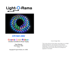
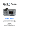
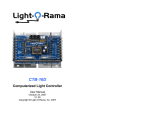
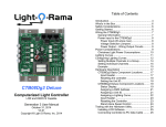
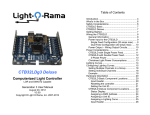
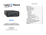
Table of Contents CB100D DMX Cosmic Color Bulbs Includes Controller with Power Supply User Manual December 2, 2014 V1.3 Copyright © Light O Rama, Inc. 2012-2014 Introduction .............................................................. 4 What’s in the Box..................................................... 5 Hardware Utility Version .......................................... 5 Firmware Version .................................................... 5 Power Line Control (PLC) ........................................ 6 Detailed Bulb Description ........................................ 6 Important Considerations ........................................ 7 Hardware Configuration ........................................... 8 Assigning a Unit ID .............................................. 8 Setting the Configuration ................................... 10 Unit ID Mode (Default is Dual Normal) ........... 11 Channel Mode ................................................ 11 Resolution ...................................................... 12 Number of end-to-end ribbons/strings ............ 12 First Pixel is Status Indicator .......................... 13 CCP (Pixel) Color Correction.......................... 13 Flip String 1 & Flip String 2 ............................. 13 DMX Mode (Default is Channels Only) ........... 13 Software Control .................................................... 16 Resolution, Macro & Color Channels ................. 16 Logical Resolution .............................................. 17 Color Effects ...................................................... 18 Macros ............................................................... 18 Hardware Description ............................................ 19 Status LED ......................................................... 19 Blinking First Bulb .............................................. 20 Reset Button ...................................................... 20 Bulb String Connectors ...................................... 20 LOR Network Jacks ........................................... 20 Accessory Power Jumper .................................. 21 AC power input .................................................. 21 Data Cable Installation ....................................... 21 CB100D Connecting the CB100D to a PC ........................... 22 Connecting to a Show Director .............................. 23 Connecting to another Controller ........................... 23 Updating the CB100D Firmware ............................ 23 LOR Unit ID to DMX Address Table ...................... 26 Specifications ........................................................ 27 Introduction The Light-O-Rama (LOR) Cosmic Color Bulbs (CCB) are strings of RGB LED lights. They come in two forms; C7 style Christmas lights (bulbs) and tubes with a large LED at the end (pixels.) They include a controller with a built in universal voltage power supply. One or two 50-bulb strings can be plugged into the controller. The controller understands and automatically detects both LOR and DMX protocols. Command data to the controller can be supplied by cabling it into the daisy-chain with other controllers, or, by modulating the command data on the AC power to the controller using a LOR Power Line Control (PLC) Injector. Each bulb in a string has a bright RGB LED capable of sixteen million colors. The bulbs can be controlled individually. The 50 bulbs are spaced on six inch centers. The entire system is weatherproof and UV resistant. The Windows Showtime software is used to design and build Sequences (controller commands that may be choreographed to audio/music.) These user created sequences and/or pre-programmed musical sequences available from LOR and other companies are then arranged into Shows. These shows are played by your PC or one of the LOR Show Directors. The CCB controller automatically detects 19.2K, 57.6K, 115.2K and 500K LOR network speeds or DMX. Page 4 CB100D What’s in the Box One or two 50 bulb strings 320 channel controller in a plastic weatherproof box Universal power supply built into the controller User manual The only item needed to daisy chain the ribbon into your network is a Cat5 cable. This manual is also available at www.lightorama.com ► Support ► Documentation ► CB100D User’s Manual. Hardware Utility Version The version of the Hardware Utility appears in the title bar to the right of “Light-O-Rama Hardware.” If the version number is less than 3.1.xxx, then you should get a new Hardware Utility if your license allows. Download the latest version of the Showtime software from this location: www.lightorama.com ► Support ► Sn Download. This is a full ShowTime Software download that includes the latest Hardware Utility. Firmware Version CB100D Power Line Control (PLC) The CCB controller can accept commands from a data cable or it can accept commands modulated on the AC power to the controller. This latter option is called Power Line Control (PLC.) An additional device called an Injector is used to take the LOR or DMX commands from a data cable and place these commands on the power line. The Injector plugs into your AC power. The network data cable(s) plug into the Injector. Ordinary AC extension cord(s) are run from the Injector to the CCB controllers. PLC control is uni-directional. This means that commands can only be sent to the CCB controllers. There is no way for the CCB controllers to send data back. This means that you must use a data cable to the controller when you are using the Hardware Utility to set the Unit ID or configure a CCB controller. Detailed Bulb Description A bulb string is 26.5 feet long, 24.5 feet of bulbs on 6” centers and a 2 foot leader to the controller. The C7 bulb bases and wires are green. The illuminated part of the C7 bulb is clear faceted plastic that diffuses the RGB LED in the bulb base. This document reflects CB100D firmware version 1.18. The firmware version is determined by using the Refresh button in the Hardware Utility. The CCB controller must be connected with a data cable to the PC, PLC control (see next page) using an Injector will not work in this case. The cylindrical pixel bulbs are tubes of translucent plastic with a large RGB LED at one end. They are designed for sign construction. Page 5 Page 6 The following picture shows the relative sizes. CB100D CB100D The C7 Christmas bulb string should not be subjected to weight beyond its own. In other words, support the string if you are hanging it where ice may form or winds may stress the string. The pixel bulb string should always be supported because both wires enter the bottom of the bulb and pulling on these wires can allow water to enter the bulb even though it is sealed with glue. Note that LOR cannot warranty a bulb string that has been cut. LOR does stock bulb string sections that can be purchased should you damage your string. There are 50 integrated circuits (ICs,) one in each bulb. Each of these ICs can be controlled independently. The IC provides 256 levels of brightness for red, 256 levels for green and 256 levels for blue, allowing for 16 million colors. Important Considerations The weatherproof box can be mounted in any position if PLC control is being used. If the plug allowing data cable(s) is used, then the box must be mounted with the data cable wire(s) downward. In either case, no forced water spray toward the controller is permitted. The mounting tabs on the top of the box should be attached upward. The CCB controller does NOT supply 9vdc accessory power. This means that LOR accessories like RF-V4 wireless units, show directors or the SC485 serial data connector will require an additional power source or another LOR controller that does supply accessory power. Page 7 Hardware Configuration Assigning a Unit ID If you have not installed the Light O Rama Windows Showtime Software, do it now. You will also need one of the USB RS485 adapters installed. See the Connecting the CB100D to a PC section for more information. Make sure the CCB controller is unplugged and open the controller case. Use a Cat5 LAN cable to connect your USB RS485 adapter to the CCB controller. Plug the CCB controller into AC power. The Status LED will blink about twice/second. This means that the controller has booted and is waiting for the PC to talk to it. Start the Hardware Utility – click start ► All Programs ► Light-O-Rama ► Light-O-Rama Control Panel. There will be a light bulb with a red halo on the right side of the task bar at the bottom Page 8 CB100D of the screen. Right-click the light bulb and select Hardware Utility from the menu. Make sure the LOR Control tab is selected. You will this window: CB100D 3. Click the Change Unit ID button to set your CB100D unit ID. You will see a Unit ID Changed box – click OK. Setting the Configuration The Hardware Utility is used to set the power-up configuration of the CCB controller. Of the parameters configured below, only the Logical Resolution/Flip-status can be changed on-the-fly in sequences. All other parameters are set by and can only be changed by the Hardware Utility. Click the Refresh button to find your CCB controller. The CCB controller must appear in the drop-down menu to the right of the Refresh button in order to continue. Click the Auto Configure button in the Setup Comm Port section. The Hardware Utility will search for the COM port that your USB RS485 adapter is plugged into and select it. The Cosmic Color Bulbs are configured via a subscreen reachable from the LOR Control tab. First, click the LOR Control tab, then click the Configure button at the bottom of the window and then you will see the window below: When assigning a unit ID, only one controller may be plugged into the USB RS485 adapter on the PC. Be sure you do not have more than one controller connected. Steps to set/change unit ID: 1. In the Change Existing ID section, use the Old Unit ID drop-down menu to select Any Unit, then click OK in the warning box for changing all unit IDs, there should only be one unit attached. 2. Use the New Unit ID drop down menu to select “01” or whatever Unit ID you want. Page 9 Page 10 CB100D Click the CCR-CCB Config button and the following window will appear. Use this window to set select the startup configuration. Remember to click the Update Unit button to send your configuration to the controller. CB100D Triples means the channels will appear as R (channel 1) G (channel 2), B (channel 3) for the first pixel (the pixel nearest the controller,) then R (4), G (5), B (6) for the next pixel, etc. Sequential means that all the Rs (channel 1, 2, 3, …) will come first, then all the Gs and finally all the Bs. Resolution Logical resolution is the number of pixels that a bulb string appears as in the Sequence Editor. This must be set to 50 if you intend to use the Resolution, Macro & Color Effect channels. You can always change the logical resolution on the fly using the Resolution channel. Normal means one unit ID for all 320 channels. A bulb string has 50 physical pixels (bulbs,) but to make programming less tedious, it can be set to a lower logical resolution. This means that adjacent physical pixels (bulbs) will be merged. E.g. If the string is set to a logical resolution of 5 pixels, then 10 adjacent bulbs will respond as one – the string will appear to be 5 segments. Legacy means up to twenty sequential unit IDs depending upon the configured logical resolution. Number of end-to-end ribbons/strings Dual Normal means two consecutive unit IDs. The configured unit ID is string 1 and ID+1 is string 2. Sets the number of end-to-end connected bulb strings. This is not implemented at this time. Unit ID Mode (Default is Dual Normal) Channel Mode Channel Mode is the order in which the pixel channels appear in the Sequence Editor. The number of channels depends upon the configured resolution. Page 11 1. The controller supports a maximum of 50 physical pixels per bulb string. As bulb strings are added end-to-end, adjacent pixels are combined to limit the number of pixels to 50. E.g. for two bulb strings, a physical pixel becomes 2 adjacent bulbs. Page 12 CB100D 2. A 2 amp 5 vdc power supply is required for each additional bulb string. This is because the voltage drop is too great for more than 50 bulbs and colors will be incorrect. Also, the CCB controller has power for a maximum of 100 bulbs (two 50-bulb strings.) 3. The theoretical limit on the number of end-toend connected bulb strings is 4. CB100D After the first LOR controller or Injector, you can use Cat5 LAN cables to daisy chain additional DMX capable LOR controllers and/or Injectors. Channels Only DMX Mode Only the RGB channels will appear. The number of channels is dependent upon the logical resolution configured. The order of the channels is dependent upon the Channel Mode configured. First Pixel is Status Indicator See Blinking First Bulb section. CCP (Pixel) Color Correction This must be check for pixel (as opposed to bulb) strings. Flip String 1 & Flip String 2 Normally, the first pixel is the bulb nearest the controller. Checking the “Flip string n” box reverses this making the bulb furthest from the controller the first pixel. If you stretch out the two strings, the controller will be in the middle. Flipping string 1 will make it look like a 100 bulb string when addressing the 100 RGB channels in the Sequence Editor. Configured resolution in logical pixels/string DMX Channel Offset from start address – string1/string2 for first RGB channel 50 0/150 = 300 channels 25 0/75 = 150 channels 17 0/51 = 102 channels 16 0/48 = 96 channels 10 0/30 = 60 channels 5 0/15 = 30 channels 2 0/6 = 12 channels 1 0/3 = 6 channels DMX Mode (Default is Channels Only) Selects how the CB100D will appear in a DMX universe. The CCB controller and the Injector have RJ45 network connections. You will need the LOR RJ-45 to XLR 3-pin Male connector to connect the controller to a DMX universe. It is available from the Web Store on the accessories page: www.lightorama.com/ ► LOR Store ► Accessories ► RJ-45 to XLR 3-pin Male Page 13 Effects Only DMX Mode Only the macros and color effect channels will appear. There will be 32 channels. DMX Channel Offset from start addr string1/string2 Controls Page 14 CB100D 0-4/16-20 Macro mode 5/21 Macro submode 6/22 Macro effect 7/23 Logical resolution 8-12/24-28 Color effect 13/29 Color speed 14/30 Color brightness 15/31 Reserved See this manual: www.lightorama.com ► Support ► Documentation ► Cosmic Color Pixel Manual for DMX values to functions for these channels. Both Channels & Effects DMX Mode The 32 macro/color effect channels will appear followed by the RGB channels. For more detailed information on DMX use of LOR controllers see: www.lightorama.com ► Support ► Downloads ► DMX Information Macro & Color Effects in DMX To see how DMX values affect the macro & color effect channels when controlling the bulbs via DMX, see the Cosmic Color Pixel Manual available here: www.lightorama.com ► Support ► Downloads ► Cosmic Color Pixel Manual Page 15 CB100D Software Control The CB100D appears in a LOR Network at the unit ID set by the Hardware Utility, or it can appear as up to 20 consecutive unit IDs when run in legacy mode, or each string can appear as a separate unit ID. (see the Unit ID Mode section) It is configured in the Sequence Editor as up to 320 channels. Each bulb string appears as 160 channels. The first 150 channels are the R, G & B channels for the 50 physical pixels. These channels can be combined into Sequence Editor RGB channels cutting the 150 to 50. The next 10 channels are the resolution, macro and color effect channels. The second bulb string’s channels follow the first and have the same layout. When the controller is configured for 50 pixel resolution per bulb string with triples (RGB) channel mode, string 1’s first pixel is channels 1(R), 2(G) & 3(B). String 2’s first pixel is channel 161(R), 162(G) & 163(B). Resolution, Macro & Color Channels Because of the large number of controllable elements, the CB1000D introduces some concepts designed to dramatically simplify programming the bulb strings. nnn/mmm indicate the LOR channel number for bulb string 1/bulb string 2. Channel 151/311 – Current logical resolution Channel 152/312 – Macro mode Channel 153/313 – Macro submode Channel 154/314 – Macro effect control Channel 155/315 – Color effect mode Channel 156/316 – Color speed Page 16 CB100D Channel 157/317 – Color intensity Channels 158-160/318-320 – Reserved Logical Resolution This channel allows the logical resolution of a bulb string to be changed on the fly. The logical resolution is the number of pixels the bulb string appears as in the Sequence Editor. A bulb string has a physical resolution of 50 pixels. This means the string can appear as up to150 regular channels or 50 RGB channels. If the resolution channel is set to one of the following intensities, adjacent bulbs may be combined to reduce the channel count: 1, 2, 5, 10, 16, 17, 25 & 50 Adding 50 to the resolution ‘flips’ the pixels. E.g. if the configured resolution is normal orientation 50, this means that the bulb string appears as 50 separate pixels and the bulb nearest the controller is pixel 1. If the resolution channel is set to 100 (50 + 50) then the bulb string will appear as 50 separate pixels, but pixel 1 will be the furthest bulb from the controller. Values other than the supported resolutions or the supported resolutions plus 50 will select the resolution configured with the Hardware Utility. When the resolution channel is set to intensity ‘1,’ a single RGB channel (or 3 normal channels) will set the color/intensity of an entire bulb string. When set to ‘5,’ five RGB channels (or 15 normal channels) will set the color/intensity of the 5 equal segments of a bulb string. Page 17 CB100D Note that resolutions 16 & 17 do not divide evenly into 50 pixels. In the case of 16, the logical pixels at the ends of a string have one more physical pixel than the center logical pixels. In the case of 17, the center logical pixel has one fewer physical pixels than all the others. In Triples mode channel numbering, only as many RGB triples as are necessary to address the current resolution are used. I.e. the first five sets of RGB channels if the logical resolution is set to 5. In Sequential mode, the number of channels used causes the points where the G and B channels start to move. I.e. for string 1, the first G channel will be 51 if the logical resolution is 50. The first G channel will be 6 if the logical resolution is 5. This was done for legacy support and DMX. Color Effects There are two ways to manipulate the colors and/or intensities of the logical pixels. The most familiar way is to set or fade the RGB channels. This permits great control but can be tedious. The second way is to use a Color Effect. When using a color effect, the RGB channels should be off. See the Cosmic Color Pixel Manual available here: www.lightorama.com ► Support ► Documentation ► Cosmic Color Pixel Manual Macros Macros are effects that can be placed ‘on top’ of the RGB channels or a Color Effect. Macros can be thought of as masks that expose the underlying RGB pixels in interesting ways. Page 18 CB100D Macro effects always run at the full 50 physical pixel resolution of the bulb string regardless of the current logical resolution setting. Logical resolution only affects the RGB or Color Effect channels. See the Cosmic Color Pixel Manual available here: www.lightorama.com ► Support ► Documentation ► Cosmic Color Pixel Manual Hardware Description CB100D firmware is not loaded or corrupted. See the Updating the CB100D Firmware section to load firmware Flashing rapidly indicates resetting because you are holding the reset button during power up Blinking First Bulb The status LED will be mirrored on the green LED of string one’s bulb nearest the controller. This will occur for 60 seconds after the controller is powered up. This was done because it is a nuisance to open the controller box and see the actual status LED. This can be suppressed in the configuration. Reset Button Resetting the controller sets all parameters except the Unit ID back to the factory defaults. Press and hold this button when powering up the controller to reset it. After resetting, the controller will run a simple pattern on the bulb strings. Press this button after the controller has booted to activate trigger 3. Bulb String Connectors Status LED Blinks twice per second if the CB100D has booted correctly but is not connected to an active network Solid on if the CB100D sees a network director – either a PC or Show Director Blinks one long on and a short off repeatedly if in the bootloader. This means that the Page 19 The bulb string connectors have arrows on the outside and a notch on the inside to insure proper alignment when connecting bulbs strings. LOR Network Jacks Two RJ45 jacks used to daisy chain this controller into a LOR network. Accessory power is NOT available from these jacks. Page 20 CB100D Accessory Power Jumper When installed, 5vdc will be available on the LOR Network. Most LOR accessories require 9vdc. AC power input The AC power input is designed to work from 100 to 250 VAC. Data Cable Installation The CCB controller comes with two rubber plugs that fit into the large hole next to the power cord. One plug is solid and is used to completely seal the controller when using Power Line Control. The other rubber plug has two holes for data cables and is split to allow the cables to be run through the plug. You can run the cables through the plug and leave enough extra cable to reach the end of the RJ45 jacks on the controller board. Then push the plug firmly into the controller: CB100D Insert the two cables into the jacks after the plug has been firmly seated in the controller. Connecting the CB100D to a PC You will need the following to connect your CB100D controller to a PC: Showtime Windows Software USB RS485 Adapter CAT5e LAN cable Your CB100D controller Windows PC running Windows XP, Vista or Win7 The first three items are available in the LOR SPKST Generic Starter Package. www.lightorama.com ► LOR Store ► Components. You will have to choose an RS485 adapter type. Choose the USB485 if you have no intention of going wireless from your PC to the controller. If wireless is desired, get the USB485B. The following diagram shows how the pieces fit together: 1. Your PC running the Showtime Windows Software 2. Your PC speakers to play the music Page 21 Page 22 CB100D 3. RS485 Adapter to convert short distance USB to long distance RS485 4. CAT5e LAN cable 5. CB100D controller If your USB adapter has more than one jack, you can use either. You can use either jack on the CB100D. Connecting to a Show Director You will need the following to connect your CB100D controller to a Show Director: LOR1602MP3 Show-in-a-Box controller (has an internal DC-MP3 Show Director), mDMMP3 Show Director or DC-MP3 Show Director CAT5e LAN cable Your CB100D controller A 9 to 10 vdc power supply for the mDMMP3 or DC-MP3 Show Directors CB100D The CB100D powered and connected to the PC via one of the RS485 adapters – Do not use wireless Get the latest firmware. www.lightorama.com ► Support ► Firmware section. Click the Firmware button in the CB100D line and save the firmware file on your PC. Note where on your PC you have saved the firmware file. Start the LightORama Control Panel if it is not running by clicking start ► All Programs ► LightO-Rama ► Light-O-Rama Control Panel. The Light-O-Rama light bulb icon will appear in the system tray on the lower right of your screen. Start the Hardware Utility by right-clicking the Light-O-Rama Control Panel light bulb and selecting Hardware Utility from the menu. You can click the Refresh button to search for connected controllers and select the one you want to update. Click the Firmware button in the LOR Control tab and you will see this window: You can use either of the larger jacks on the show director and either jack on the CB100D. Connecting to another Controller You can go from either large jack on one controller to either large jack on the other controller. Updating the CB100D Firmware You must have: Hardware Utility version 2.3.6 or later, see the section Hardware Utility Version Page 23 Page 24 CB100D In Step 1 – Select Unit, Choose Selected unit listed above or Only one unit is connected as appropriate. In Step 2 – Select firmware file, click the Open button. Use the Open file box to select the firmware file. This is the .lhx file you saved. Click the Open button. The window will look like this: CB100D LOR Unit ID to DMX Address Table The Hardware Utility is used to set the Unit ID of the controller. See the section Assigning a Unit ID for more information. The controller must be set to one of the LOR Unit IDs listed in the following table to recognize DMX protocol. E.g. setting the LOR Unit ID to “06” will result in the first DMX address for the controller being 81. LOR DMX Unit ID Address In Step 3 – Press Download Button, click the Download button – the firmware download will start automatically. The Update progress bar will fill from left to right. When the new firmware is loaded, the Status will change to “Successful” and the CB100D will reboot. Page 25 LOR DMX Unit ID Address “01” 1 “11” 257 “02” 17 “12” 273 “03” 33 “13” 289 “04” 49 “14” 305 “05” 65 “15” 321 “06” 81 “16” 337 “07” 97 “17” 353 “08” 113 “18” 369 “09” 129 “19” 385 “0A” 145 “1A” 401 “0B” 161 “1B” 417 “0C” 177 “1C” 433 “0D” 193 “1D” 449 “0E” 209 “1E” 465 “0F” 225 “10” 241 “1F” 481 “20” 497 Page 26 CB100D Specifications Bulb string configuration 50 RGB LEDs on 6” centers Bulb string length 24.5’ from first to last bulb for each 50 bulb string First bulb to controller connector 2’ Bulbs strings per 2 (can be RGB Christmas, controller RGB pixel or both types) C7 Bulb 2” H x 1” diameter Pixel Bulb 1½” H x 7/16” diameter Operating temperature -20º F to 140º F Operating environment Outdoor, weather resistant and UV resistant Power requirements 100-240 VAC 0.3 amp @120 VAC 0.15 amp @240 VAC Controller dimensions 7¼” L x 5” W x 1½” H Light-O-Rama, Inc. Tel: (518) 539-9000 Fax: (518) 538-0067 [email protected] Page 27