1
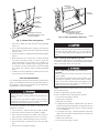
If filter is installed in furnace blower compartment:
1. Turn off electrical supply to furnace.
2. Remove main furnace door and blower access panel.
PLUG
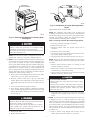
3. Release filter retainer wire. (See Fig. 3 or 4.)
CAP
4. Slide filter out of furnace.
COLLECTOR BOX
DRAIN TUBE (BLUE
& WHITE STRIPED)
5. Furnaces are equipped with permanent, washable filter(s).
Clean filter by spraying cold tap water through filter in
opposite direction of airflow.
COLLECTOR BOX
TUBE (PINK)
6. Rinse filter and let dry. Oiling or coating filter is not
recommended.
7. Slide filter into furnace.
COLLECTOR BOX
TUBE (GREEN)
8. Recapture filter retainer wire.
9. Replace blower access panel and main furnace door.
INDUCER HOUSING
(MOLDED) DRAIN
TUBE (BEHIND
COLLECTOR BOX
DRAIN TUBE)
10. Turn on electrical supply to furnace.
Step 2—Blower Motor and Wheel Maintenance
To ensure long life, economy, and high efficiency, clean accumulated dirt and grease from blower wheel and motor annually.
COLLECTOR BOX
DRAIN TUBE (BLUE)
CONDENSATE
TRAP
The inducer and blower motors are pre-lubricated and require no
additional lubrication. These motors can be identified by the
absence of oil ports on each end of the motor.
FIELD-INSTALLED
FACTORY-SUPPLIED
DRAIN TUBE
COUPLING (LEFT
DRAIN OPTION)
The following items should be performed by a qualified service
technician.
Clean blower motor and wheel as follows:
1. Turn off electrical supply to furnace.
FIELD-INSTALLED
FACTORY-SUPPLIED
DRAIN TUBE
2. Remove main furnace door and blower access panel.
3. Disconnect blower motor wires from furnace control.
Field thermostat connections may need to be disconnected
depending on their length and routing.
FIELD-INSTALLED
FACTORY-SUPPLIED
1⁄2-IN. CPVC STREET
ELBOWS (2) FOR
LEFT DRAIN OPTION
4. Remove control box mounting screws and position control
box, transformer, and door switch assembly to right side of
furnace casing.
A01030
→
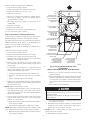
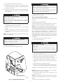
5. If condensate trap is located in left- or right-hand side of
furnace casing, proceed to item 6, otherwise remove trap and
tubing as described below (See Fig. 5):
Fig. 5—Factory-Shipped Upflow Tube
Configuration
(Shown with Blower Access Panel Removed)
d. Remove screws securing cutoff plate and remove cutoff
plate from housing.
a. Disconnect field drain connection from condensate trap.
b. Disconnect drain and relief port tubes from condensate
trap.
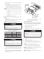
e. Remove bolts holding motor mounts to blower housing and
slide motor and mounts out of housing. Disconnect capacitor and ground wire attached to blower housing before
removing motor. Motor mounts need not be removed from
motor.
c. Remove condensate trap from blower shelf.
6. Remove screws securing blower assembly to blower shelf and
slide blower assembly out of furnace. Detach ground wire and
disconnect blower motor.
→ NOTE:
FIELD-INSTALLED
FACTORY-SUPPLIED
DRAIN TUBE
COUPLING (RIGHT
DRAIN OPTION)
f. Remove blower wheel from housing.
Blower wheel is fragile. Use care.
7. Clean blower wheel and motor by using a vacuum with soft
brush attachment. Be careful not to disturb balance weights
(clips) on blower wheel vanes. Do not bend wheel or blades as
balance will be affected.
UNIT DAMAGE HAZARD
Failure to follow this caution may result in noise or furnace
component failure.
The blower wheel should not be dropped or bent as balance
will be affected.
8. If greasy residue is present on blower wheel, remove wheel
from the blower housing and wash it with an appropriate
degreaser. To remove wheel:
g. Clean wheel per instructions on degreaser cleaner. Do not
get degreaser in the motor.
a. Mark blower wheel location on shaft before disassembly to
ensure proper reassembly.
9. Reassemble motor and blower wheel by reversing items 8b
through 8f. Ensure wheel is positioned for proper rotation.
Tighten set-screw to 140-160 in.-lb torque.
b. Loosen setscrew holding blower wheel on motor shaft.
NOTE: Mark blower mounting arms and blower housing so each
arm is positioned at the same hole location during reassembly.
→ NOTE:
Be sure to attach ground wire and reconnect blower
harness plugs to blower motor.
c. Mark blower wheel orientation and cutoff plate location to
ensure proper reassembly.
10. Reinstall blower assembly in furnace.
4