1
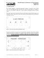
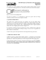
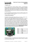
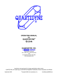
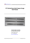
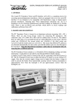
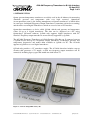
AVA-08 Frequency Transducer to Q-Link Interface
22-Apr-2015
Page 1 of 9
1. INTRODUCTION
Quartz pressure/temperature transducers are widely used in the oil industry for measuring
downhole pressure and temperature with very high accuracy. Quartzdyne
(www.quartzdyne.com) is the leading manufacturer of quartz transducers, of which there
are two types: traditional Frequency Output Transducers (sometimes referred to as analog)
and the more recent Digital Transducers, which are accessed via an I²C interface.
Quartzdyne manufactures a device called Q-Link, which reads pressure and temperature
values of up to 4 digital transducers. The data can be displayed on a PC using
Quartzdyne's QConsole software. Q-Link only supports digital transducers with I²C
interface. Frequency output transducers are not directly supported by Q-Link.
The AVA-08 Frequency Transducer to Q-Link Interface fills this gap. It connects between
a Q-Link device and up to 4 frequency output transducers. It measures pressure and
temperature frequencies and makes them available to Q-Link via I²C. The AVA-08
appears to Q-Link as a set of digital transducers.
Q-Link only provides a 3V transducer supply. The AVA-08 therefore includes step-up
circuitry that generates a 5V supply, so that any frequency output transducer can be
connected, including legacy types that would not work below 5V.
Figure 1: AVA-08 and Q-Link side by side.
© Avanti Elektronik Limited - (44) 01224-583132 - www.avanti.clara.net - [email protected]
qlink_10.doc
AVA-08 Frequency Transducer to Q-Link Interface
22-Apr-2015
Page 2 of 9
2. CONNECTIONS
The AVA-08 contains 4 electrically independent channels. It connects to the Q-Link
device via 6-pin Mini-Din cables (male-male), one cable for each channel. If a channel is
not in use (no transducer connected), its cable should be unplugged from the Q-Link
device.
The cables should not be longer than 2m and of good quality (ideally shielded). Beware of
cheap PS-2 cables, which may not have all of the pins wired through (mice and keyboards
only require 4 wires).
Figure 2: AVA-08 Rear Panel with 6-pin Mini-Din Sockets.
Frequency transducers are connected via 9-way D-Type connectors. The pin-out is printed
onto the front panel and follows the standard Avanti simulator pin-out for frequency
transducers. Note that Quartzdyne transducer cables that are terminated with a Dtype plug have a different pinout.
Figure 3: AVA-08 Front Panel with 9-way D-Type sockets.
© Avanti Elektronik Limited - (44) 01224-583132 - www.avanti.clara.net - [email protected]
qlink_10.doc
AVA-08 Frequency Transducer to Q-Link Interface
22-Apr-2015
Page 3 of 9
3. I²C INTERFACE
The AVA-08 is based on AVA-07 frequency counters. These counters provide an I²C
interface, which is compatible but not identical to the I²C implementation in a Digital
Quartzdyne Transducer. The AVA-08 therefore has the same I²C restrictions as the AVA07. For details see the AVA-07 user manual.
These I²C restrictions however do not pose a problem when connected to a Q-Link device.
The AVA-08 has been proven to be fully functional with the latest Q-Link firmware
revision (REV_A5) and QConsole software revision (V2.8).
4. CALIBRATION COEFFICIENTS
The AVA-08 is preloaded with dummy coefficients, which report the transducer model as
AVANTI and the serial number as AAAAAAAA, BBBBBBBB, CCCCCCCC or
DDDDDDDD depending on the channel (A, B, C or D) being used. The preloaded dummy
coefficients translate frequencies 1:1 into psi and °C, e.g. a pressure frequency of 20000Hz
will be displayed as 20000psi in QConsole and a temperature frequency of 30000Hz will
be displayed as 30000°C.
The dummy coefficients are read from the AVA-08 EEPROM after Q-Link is powered up.
They allow a quick check of pressure and temperature frequencies and remain active until
proper calibration coefficients are loaded from file.
Q-Link only handles coefficients in digital format, i.e. in the form of a .HEX file.
Coefficients for frequency transducers are normally supplied in a different format in the
form of two separate files, a .CRF file for pressure coefficients and a .CRT file for
temperature coefficients.
A conversion utility CFFconv is available from Avanti, which extracts the information
contained in .CRF/.CRT files and generates a .HEX file for use with Q-Link. This is a
simple one-click operation. The CFFconv software utility can be downloaded from
www.avanti.clara.net/cffconv.zip
Note that the preloaded dummy coefficients are write protected. It is therefore not possible
to permanently alter these coefficients in QConsole, unless the enclosure is opened and a
jumper link is removed (see below).
5. INTERNAL JUMPER LINKS
There are two internal jumper links contained in the AVA-08.
One of the jumper links controls the write protection of the internal EEPROM. If the
jumper is inserted, the EEPROM is write protected, if the jumper is removed, the
EEPROM contents can be altered. The AVA-08 is shipped with the jumper inserted.
The second jumper link controls the counting mode. If the jumper is removed, the counters
count over a period of 1sec with updates every 91ms. If the jumper is inserted, the
counting period follows the polling rate and adjusts itself between 91ms and 2.8sec. The
© Avanti Elektronik Limited - (44) 01224-583132 - www.avanti.clara.net - [email protected]
qlink_10.doc
AVA-08 Frequency Transducer to Q-Link Interface
22-Apr-2015
Page 4 of 9
91ms update rate remains unaffected. The AVA-08 is shipped with the jumper removed,
i.e. with a fixed counting period of 1sec. For further details see the AVA-07 user manual.
Figure 4: Location of AVA-08 Jumper Links
To open the enclosure, it is recommended to unscrew the panel with the D-Type
connectors and then to slide out the complete assembly.
6. Q-LINK POWER SUPPLY
The Q-Link device contains four linear 3V regulators, one for each channel. These
regulators are very small and can therefore dissipate only a limited amount of heat. The
current drawn by the AVA-08 from the 3V supply is approximately 30mA, including a
typical frequency output transducer. This is significantly more than a digital transducer
would draw, due to stepping up the transducer supply to 5V.
It is therefore essential to power the Q-Link device from a regulated power supply not
exceeding 5V max. Q-Link works with input voltages as low as 3.3V. A regulated 3.3V
PSU is therefore recommended.
Caution: Always power down Q-Link while connecting/disconnecting transducers.
7. OPERATION STEP BY STEP
a) Make sure power is removed from Q-Link. Connect 1...4 transducers to the AVA-08
interface. Connect a Mini-Din cable for each channel in use and plug the other end into the
Q-Link device. Connect the Q-Link device to the serial port of a PC. Then apply power.
b) Start QConsole software and register all connected transducers by pressing CONNECT.
QConsole will display a screen as shown below. Note the Model Number AVANTI and
the serial number AAAAAAAA, indicating that dummy coefficients are used, which were
read from the AVA-08 EEPROM.
© Avanti Elektronik Limited - (44) 01224-583132 - www.avanti.clara.net - [email protected]
qlink_10.doc
AVA-08 Frequency Transducer to Q-Link Interface
22-Apr-2015
Page 5 of 9
c) If the READINGS tab is pressed, all connected transducers are displayed as shown
below. Due to the dummy coefficients loaded from EEPROM, psi and °C values indicate
pressure and temperature frequencies in Hz instead of true pressure and temperature.
© Avanti Elektronik Limited - (44) 01224-583132 - www.avanti.clara.net - [email protected]
qlink_10.doc
AVA-08 Frequency Transducer to Q-Link Interface
22-Apr-2015
Page 6 of 9
d) In order to get real pressure and temperature values, valid coefficients must be loaded
from a .HEX file. If not already done, use Avanti's CFFconv utility to generate a .HEX file
from .CRF/.CRT files. Then open the .HEX file from the COEFFICIENTS tab.
© Avanti Elektronik Limited - (44) 01224-583132 - www.avanti.clara.net - [email protected]
qlink_10.doc
AVA-08 Frequency Transducer to Q-Link Interface
22-Apr-2015
Page 7 of 9
e) Then press LOAD COEFFICIENTS to copy the coefficients into Q-Link. Untick the
MAKE CHANGES PERMANENT box, since the EEPROM of the AVA-08 is write
protected and cannot be changed permanently.
f) Go back to the EZCommands tab and select the next transducer's address.
g) Repeat loading coefficients from file (steps d and e) until all connected transducers are
done.
h) Go back to the READINGS tab and press again CONNECT until all transducers are reregistered and the coefficients loaded from file come into effect.
© Avanti Elektronik Limited - (44) 01224-583132 - www.avanti.clara.net - [email protected]
qlink_10.doc
AVA-08 Frequency Transducer to Q-Link Interface
22-Apr-2015
Page 8 of 9
i) The READINGS screen now shows correct psi and °C values of all transducers together
with their correct serial numbers.
8. SPECIFICATION
Supply Voltage
Supply Current (including transducer)
Counting Reference
Update Rate
Gate Time
Dimensions / Weight
3.0V from Q-Link device
Approximately 30mA,
>60mA briefly on startup
FREF / 2 = 3.6MHz
91ms
91ms – 2821ms (MODE link inserted)
1001ms (MODE link removed)
105 x 125 x 55mm / 370gr
For resolution values versus gate time see the AVA-07 user manual.
9. CAUTION
-
Always power down Q-Link while connecting or disconnecting transducers.
Double check the transducer wiring before powering up.
Connect only channels that are in use (i.e. with a transducer connected) to Q-Link.
Keep the wiring at the D-Type connectors as short as possible.
Keep the length of the Mini-Din cables below 2 meters.
© Avanti Elektronik Limited - (44) 01224-583132 - www.avanti.clara.net - [email protected]
qlink_10.doc
AVA-08 Frequency Transducer to Q-Link Interface
22-Apr-2015
Page 9 of 9
10. ACKNOWLEDGEMENTS AND FURTHER INFORMATION
Quartzdyne is a trademark of Quartzdyne Inc.
Information on their range of pressure transducers and the Q-Link device can be
downloaded from their web-site at http://www.quartzdyne.com
I²C is a trademark of NXP Semiconductors (formerly Philips).
Specifications and application notes can be downloaded from their web-site at
http://www.nxp.com
Avanti Part Number:
AVA-08
Avanti Serial Number:
0001
Tested:
© Avanti Elektronik Limited - (44) 01224-583132 - www.avanti.clara.net - [email protected]
qlink_10.doc