1
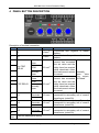
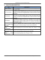
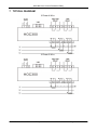
HOC300 Over Current Protection Relay User Manual Smartgen Technology Chinese trademark English trademark Smartgen — make your generator smart Smartgen Technology Co., Ltd. No. 28 Jinsuo Road Zhengzhou Henan Province P. R. China Tel: +86-371-67988888/67981888 +86-371-67991553/67992951 +86-371-67981000(overseas) Fax: 0086-371-67992952 Web: http://www.smartgen.com.cn http://www.smartgen.cn Email: [email protected] All rights reserved. No part of this publication may be reproduced in any material form (including photocopying or storing in any medium by electronic means or other) without the written permission of the copyright holder. Smartgen Technology reserves the right to change the contents of this document without prior notice. Software Version Version 1.0 1.1 Date 2014-08-07 2014-10-09 Note Original release. Rename the product. HOC300 Over Current Protection Relay This manual is suitable for HOC300 over current protection relay only. Clarification of notation used within this publication. SIGN NOTE INSTRUCTION Highlights an essential element of a procedure to ensure correctness. Indicates a procedure or practice, which, if not strictly observed, could CAUTION! result in damage or destruction of equipment. Indicates a procedure or practice, which could result in injury to WARNING! personnel or loss of life if not followed correctly. HOC300 Over Current Protection Relay Version 1.1 2014-10-09 Page 3 of 13 HOC300 Over Current Protection Relay CONTENT 1 SUMMARY .................................................................................................................... 5 2 PERFORMANCE AND CHARACTERISTICS ............................................................... 6 3 SPECIFICATION ........................................................................................................... 7 4 PANEL BUTTON DESCRIPTION .................................................................................. 8 5 FUNCTION DESCRIPTION .......................................................................................... 9 6 SCOPES AND DEFINITIONS OF PROGRAMMABLE PARAMETERS ....................... 10 7 TYPICAL DIAGRAM .................................................................................................... 11 8 INSTALLATION DIMENSIONS .................................................................................... 13 HOC300 Over Current Protection Relay Version 1.1 2014-10-09 Page 4 of 13 HOC300 Over Current Protection Relay 1 SUMMARY HOC300 over current protection relay is widely used in marine genset field and land genset field. HOC300 over current protection relay detects load current accurately. Over current trip or pre-trip relay outputs and alarm protection activates when the load current has exceeded the set value. HOC300 Over Current Protection Relay Version 1.1 2014-10-09 Page 5 of 13 HOC300 Over Current Protection Relay 2 PERFORMANCE AND CHARACTERISTICS Suitable for 3-phase 4-wire, 3-phase 3-wire, single phase 2-wire, and 2-phase 3-wire systems with frequency 50/60/400Hz; Detects load current accurately. Adjustable potentiometer allows for set value adjusting and delay value setting. 2 relay output; One test button, test the over current trip/pre-trip relay and indicator. Widely power supply range DC(8~35)V, suitable to different starting battery voltage environment; 35mm guide rail mounting. Modular design, pluggable terminal, compact structure with easy installation; HOC300 Over Current Protection Relay Version 1.1 2014-10-09 Page 6 of 13 HOC300 Over Current Protection Relay 3 SPECIFICATION Parameter Working Voltage Overall Consumption Pre-Trip Relay Output Trip Relay Output Case Dimensions CT Secondary Current Working Conditions Storage Conditions Insulation Intensity Weight Details DC8. 0V to 35. 0V, continuous power supply <0.9W (Standby mode: ≤0.28W) 5A AC250V Volts free output 5A AC250V Volts free output 89.7mm x 71.6mm x 60.7mm Rated 5A Temperature: (-25~+70)°C Humidity: (20~93)%RH Temperature:(-25~+70)°C Apply AC2.2kV voltage between high voltage terminal and low voltage terminal; The leakage current is not more than 3mA within 1min. 0.24kg HOC300 Over Current Protection Relay Version 1.1 2014-10-09 Page 7 of 13 HOC300 Over Current Protection Relay 4 PANEL BUTTON DESCRIPTION Description of terminal connection NO. Functions Cable Size 1 B- 1.0mm2 2 B+ 1.0mm2 Normally Open 3 4 Pre-TRIP RELAY COM 2.5 mm2 Normally Open Normally Close COM 5 6 7 2.5 mm2 TRIP RELAY 8 Normally Open 9 IL1 Dotted Terminals 1.5 mm2 IL2 Dotted Terminals 1.5 mm2 IL3 Dotted Terminals 1.5 mm2 10 11 12 13 14 LINK Port Remark Connected with negative of starter battery. Connected with positive of starter battery. Active when the load current has exceeded the set value and the delay timer has expired while deactivate when the load current returns Normally to normal. open; Volts Active when the load free output; current has exceeded 5A Rated the set value and the delay timer has expired while deactivate when the load current returns to normal. CT A-phase input; Externally connected to secondary coil of current transformer (rated 5A). CT B-phase input; Externally connected to secondary coil of current transformer (rated 5A). CT C-phase input; Externally connected to secondary coil of current transformer (rated 5A). Used for parameters setting. HOC300 Over Current Protection Relay Version 1.1 2014-10-09 Page 8 of 13 HOC300 Over Current Protection Relay 5 FUNCTION DESCRIPTION Item Power Indicator Pre-Trip Indicator Trip Indicator TEST Button TRIP /% Over Currrent Trip Set Value DELAY /s Delay Value Potentiometer Pre-TRIP /% Pre-Trip Set Value DELAY /s Delay Value Potentiometer Description Power supply indicator; It is illuminated when the relay is powered up. (green light) It flashes once per second when the load current has exceeded the set value and Pre-TRIP indicator light on when the delay timer has expired. The indicator extinguished after current returns to normal. (red light) It flashes once per second when the load current has exceeded the set value and TRIP indicator light on when the delay timer has expired. The indicator extinguished after current returns to normal. (red light) Pressing and holding the button for 3 seconds, the Pre-Trip relay and Pre-Trip indicator output; Press the button and release the button, within 1 second, again press it for 3 seconds, Trip relay and Trip indicator output. Used for adjusting over current set value. Range: (50~140)%; Setting value is the percentage of rated current value(5A). Used for adjusting over current action delay value. Range: (1~60)s Used for adjusting pre-trip set value. Range: (50~140)%; Setting value is the percentage of rated current value(5A). Used for adjusting delay value. Range: (1~60)s HOC300 Over Current Protection Relay Version 1.1 2014-10-09 Page 9 of 13 HOC300 Over Current Protection Relay 6 SCOPES AND DEFINITIONS OF PROGRAMMABLE PARAMETERS No. Items Parameters 1 AC System 2 CT Ratio (5-6000)/5 Full Load Rated (5-6000)A Current Communication (1-254) Address 3 4 (0-3) Defaults 0 Description 0: 3P4W, 1: 3P3W 2: 2P3W, 3:1P2W 500 500 1 PC Program: Parameters setting and real-time monitoring can be implemented via LINK port by using PC software and an SG72 adapter which produced by our company. As follows: HOC300 Over Current Protection Relay Version 1.1 2014-10-09 Page 10 of 13 HOC300 Over Current Protection Relay 7 TYPICAL DIAGRAM 3 Phase 4 Wire 3 Phase 3 Wire HOC300 Over Current Protection Relay Version 1.1 2014-10-09 Page 11 of 13 HOC300 Over Current Protection Relay 2 Phase 3 Wire Single Phase 2 Wire HOC300 Over Current Protection Relay Version 1.1 2014-10-09 Page 12 of 13 HOC300 Over Current Protection Relay 8 INSTALLATION DIMENSIONS 1) Output And Expand Relays All outputs are relay contact output type. If need to expand the relays, please add freewheel diode to both ends of expand relay’s coils (when coils of relay has DC current) or, add resistance-capacitance return circuit (when coils of relay has AC current), in order to prevent disturbance to controller or others equipment 2) AC Input Current input must be connected to outside current transformer. And the current transformer’s secondary side current must be 5A. Note: When there is load current, transformer’s secondary side prohibit open circuit. 3) Withstand Voltage Test CAUTION! When relay had been installed in control panel, if need the high voltage test, please disconnect relay’s all terminal connections, in order to prevent high voltage into relay and damage it. HOC300 Over Current Protection Relay Version 1.1 2014-10-09 Page 13 of 13