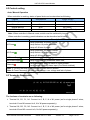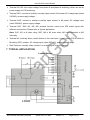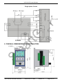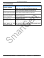
1
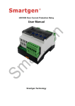
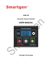
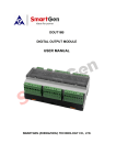
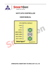
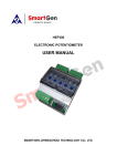
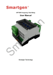
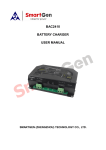
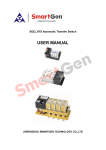
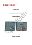
HAT150 ATS Controller USER MANUAL Smartgen Technology Smartgen Technology Co., Ltd No.28 Jinsuo Road Zhengzhou Henan Province P. R. China Tel: 0086-371-67988888/67981888 0086-371-67991553/67992951/67992952 0086-371-67981000(overseas) Fax: 0086-371-67992952/67981000 Web: http://www.smartgen.com.cn http://www.smartgen.cn Email: [email protected] All rights reserved. No part of this publication may be reproduced in any material form (including photocopying or storing in any medium by electronic means or other) without the written permission of the copyright holder. Applications for the copyright holder’s written permission to reproduce any part of this publication should be addressed to Smartgen Technology at the address above. Any reference to trademarked product names used within this publication is owned by their respective companies. Smartgen Technology reserves the right to change the contents of this document without prior notice. Software Version Date 2011-11-04 Version 1.0 Note Original release HAT150 ATS Control Module CONTENT 1 SUMMARY ............................................................................................................................ 4 2 PERFORMANCE AND CHARACTERISTICS ........................................................................ 4 3 SPECIFICATION ................................................................................................................... 5 4 SETTING PARAMETERS ...................................................................................................... 5 5 PANEL DESCRIPTION .......................................................................................................... 6 6 PANEL OPERATION.............................................................................................................. 6 6.1 Delay Adjustment ......................................................................................................... 6 6.2 Control setting .............................................................................................................. 7 6.3 Terminals Description ................................................................................................... 7 7 TYPICAL APPLICATION ........................................................................................................ 8 8 OVERALL DIMENSIONS AND INSTALLATIONS .................................................................. 9 9 FAULT FINDING .................................................................................................................. 10 HAT150 ATS Generator Controller ISSUE 2011-11-1604 Version 1.0 Page 3 of 10 HAT150 ATS Control Module 1 SUMMARY HAT150 ATS controller is an automatic control module using microprocessor as core. It can accurately detect 2-way 3-phase/single phase voltage and judge voltage abnormal (such as, loss of power, over voltage, under voltage and lack of phase), then control ATS after delay. After abnormal delay of #I power, the controller will send signal to start the genset. 2 PERFORMANCE AND CHARACTERISTICS HAT150 controller can detect 2-way 3-phase/single phase voltage (2-way mains and 2-way gens or 1-way mains and 1-way gens) and control ATS. Can achieve PC programming control, voltage abnormal delay, genset stop delay, voltage calibration and so on which all operated on graphic interface. During computer programming, the base plate of the controller must be opened, and then use SG72 interface module (USB to LINK) to program via testing software of PC; Normal delay of #I power or #II power can be set. Start delay of genset can be set; Abnormal delay of #I power or #II power can be set. Stop delay of genset can be set; “#I Priority”, “Manual”, “Mutual Backup”, “#II Priority” can be set through panel knobs. Ensure “#I Power Priority”, “#II Power Priority” or “No Priority” and maintenance; Isolated design of 2-way Neutral; Closing time of switch is 5 seconds. If detecting closing signal during this period, disconnect at once; With re-closing function. This can make open/close breaker enabled even when the positions of operating mechanism and switch are inconsistent. When 2-way power and volts are abnormal at the same time, if voltage of A phase is normal, ATS will automatically transfer to Breaking (Middle) Position; With fire reset interface. When the input port is enabled, ATS will automatically transfer to Breaking (OFF) Position; LED can display working modes of the switch clearly; Strong anti-electromagnetic interference ability, can be used under complex electromagnetic interference environment; Modular configuration design, flame-resisting ABS plastic shell, inserted type terminals connection with compact structure and easy installation. HAT150 ATS Generator Controller ISSUE 2011-11-1604 Version 1.0 Page 4 of 10 HAT150 ATS Control Module 3 SPECIFICATION Item Contents Operating Voltage AC power A1N1/A2N2 supply AC (160-280)V Power Consumption Under rated voltage, power consumption is not more than 2VA AC Voltage 3-phase AC 380V Measurement Accuracy of voltage: 2%。 Rated Frequency 50Hz/60Hz Close/Open Relay Output 7A 250VAC passive normally open Start Relay Output 7A 250VAC passive normally close LO/NO Relay Output 7A 250VAC Case Dimensions 87mm x 151mm x 114mm Panel Cutout 43.5mm x 135mm Operation Condition Temperature:(-30~+70)˚C Storage Condition Temperature:(-30~+80)˚C Weight 0.5Kg Humidity:(20~95)%RH 4 SETTING PARAMETERS Items Normal Delay of #I Volt Normal Delay of #II Volt Start Delay of Genset Volt Upper Limit Volt Lower Limit Transfer Rest Delay Abnormal Delay of #I Volt Abnormal Delay of #II Volt Description Range Time for confirming #I (1-30)s volt is normal Time for confirming #II (1-30)s volt is normal Time for confirming (1-60)s engine cranking If over the limit, volt is (50-300)V abnormal. If below the limit, volt is (50-300)V abnormal. Time between closing (1-20)s and open breaker. Default 264V (phase volt) 172V (phase volt) Note Can be set via panel potentiometer Can be set via panel potentiometer Can be set via panel potentiometer Can only be set via PC Can only be set via PC 1s Can only be set via PC Time for confirming #I volt is abnormal. (1-30)s 5s Can only be set via PC Time for confirming #II volt is abnormal. (1-30)s 5s Can only be set via PC HAT150 ATS Generator Controller ISSUE 2011-11-1604 Version 1.0 Page 5 of 10 HAT150 ATS Control Module Stop delay will begin when #I voltage is Stop Delay Of normal. Once the delay Genset is over, start signal is closed. Set the detected voltage AC Options as 3 phase 4 wires or Single phase 2 wires (1-60)s 60s Can only be set via PC 3P4W; 1P2W 3P4W Can only be set via PC Note: 1. only when A phase voltage of #I or #II is normal, above delays are enabled. 2. When setting AC option as single phase 2 wires via PC, controller should be used in single phase 2 wires input. 5 PANEL DESCRIPTION 6 PANEL OPERATION 6.1 Delay Adjustment Adjusting “#I output delay” potentiometer can adjust normal delay of #I power; Adjusting “#II output delay” potentiometer can adjust normal delay of #II power; Adjusting “genset start delay” potentiometer can adjust start signal delay when #I power is abnormal; HAT150 ATS Generator Controller ISSUE 2011-11-1604 Version 1.0 Page 6 of 10 HAT150 ATS Control Module 6.2 Control setting Auto/ Manual Operation When controller is working, status of panel knob can be described as following: Position Auto/Manual Power Priority #I Priority Auto #I Power Priority Manual Manual Mutual Backup Auto No Priority #II Priority Manual #II Power Priority / Note: When controller in Manual mode, switch must be switched by human. When controller is working, panel indicators can be described as following: Indicators Description #I Power Lamp illuminates: #I power normal; Lamp flashes: #I power abnormal; Lamp off: #I loss of power; #II Power Lamp illuminates: #II power normal; Lamp flashes: #II power abnormal; Lamp off: #II loss of power; #I Power Supply Lamp illuminates: #I power has taken load; #II Power Supply Lamp illuminates: #II power has taken load; Alarming Lamp illuminates: #I or #II failed to close breaker; Lamp flashes: auxiliary alarm input (Fire Reset enabled); Note 1: Turning the knob to Manual position can remove alarms. Note 2: Power abnormal includes under voltage, over voltage and lack of phase. 6.3 Terminals Description The fuctions of terminals are as following: Terminal A1, B1, C1, N1: Connect to A, B, C, N of #1 power (as for single phase 2 wires, terminal A1 and N1connect to A, N of #I power separately). Terminal A2, B2, C2, N2: Connect to A, B, C, N of #II power (as for single phase 2 wires, terminal A2 and N2 connect to A, N of #II power separately). HAT150 ATS Generator Controller ISSUE 2011-11-1604 Version 1.0 Page 7 of 10 HAT150 ATS Control Module Terminal LO, NO: the output voltage from phase A and phase N switching, which can act as power supply for ATS switching. Terminal Q1O: connect to auxiliary normally open contact of #I power, AC voltage input (rated 220VAC), power supply voltage. Terminal Q2O: connect to auxiliary normally open contact of #II power, AC voltage input (rated 220VAC), power supply voltage. Terminal Q1C, Q2C, M1, M2, M0: terminal function varies from ATS switch types with different connections. Please refer to Typical Application. Note: Q1C, M1 is #I close relay; Q2C, M2 is #II close relay; M0 has connected to NO internally. Terminal AL: Auxiliary alarm, switch failure or fire reset input. It can control ATS to switch to Breaking (OFF) position, AC voltage input (rated 220VAC), power supply voltage. Start Terminal: normally close contact. It is a start signal output of genset 7 TYPICAL APPLICATION 3 phase 4 wires HAT150 ATS Generator Controller ISSUE 2011-11-1604 Version 1.0 Page 8 of 10 HAT150 ATS Control Module Single phase 2 wires 8 OVERALL DIMENSIONS AND INSTALATION HAT150 ATS Generator Controller ISSUE 2011-11-1604 Version 1.0 Page 9 of 10 HAT150 ATS Control Module 9 FAULT FINDING Fault Controller inoperative Remedy Check connections of #I and #II power; Check FU1 or FU2 fuse (in the inner of controller, 10A). Switch not activate Check ATS; Check the connections between controller and ATS. #I or #II power Lamp flashes Check whether 3-phase voltage is normal or not. #I or #II power lamp Set controller as manual mode or disconnect controller, remove illuminates but switch not trip status of the switch; transfer (Auto Mode) Check the delay of the potentiometer, shorten the delay time. Set controller as manual mode or disconnect controller, remove Alarm lamp flashes trip status of the switch; Only when #I voltage is abnormal, start signal of genset Genset failed to start outputs; Check the delay of the potentiometer, shorten the delay time. Genset failed to stop when Set controller as manual mode or disconnect controller, check switch has transferred if auxiliary contact is reliably connected. HAT150 ATS Generator Controller ISSUE 2011-11-1604 Version 1.0 Page 10 of 10