1
There are many kind of application by using the module to switch Load On and Off , one main application
is the light control. If connect the com port directly to AC Line terminal ,the new smart relay calibration
technology can reduce the inrush current caused by the load and let the module work perfectly with many
kind of light like incandescent, fluorescent and LED light. This module can also connect to alternative
power supply like DC 12V to switch on/off 12V MR-16 light as follow picture.
PAN06-1/-2/-3 In Wall Dual relay(1 way) switch module
Adding to Z-WaveTM Network
In the front casing, there is an on/off button with LED indicator below which is used to
toggle switch on and off or carries out inclusion, exclusion, reset or association.
When first power is applied, its LED flashes on and off alternately and repeatedly at
2-second intervals. It implies that it has not been assigned a node ID and cannot
work with Z-Wave enabled devices.
P
Auto Inclusion
The function of auto inclusion will be executed as long as the in wall switch does not
have Node ID and just connect the switch to main power.
Note: Auto inclusion timeout is 4 minute during which the node information of
explorer frame will be emitted once every 5 seconds. Unlike “inclusion” function as
shown in the table below, the execution of auto inclusion is free from pressing the
On/Off button on the Switch.
The table below lists an operation summary of basic Z-Wave functions. Please refer
to the instructions for your Z-WaveTM Certificated Primary Controller to access the
Setup function, and to include/exclude/associate devices
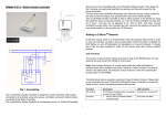
Fig 1. Assembling
Function
No node ID
This in-wall switch module is a transceiver which is a Z-WaveTM enabled device and is fully compatible
with any Z-WaveTM enabled network. Mini size design let the module can easily hide itself into the wall
box and that will be good for the house decoration.
Inclusion
1
Description
The Z-Wave Controller does not allocate
a node ID to the Switch.
1. Have Z-Wave Controller entered
inclusion mode.
LED Indication
2-second on, 2-second off
One press one flash
2.
Exclusion
1.
2.
Reset
No node ID
One press one flash
Node ID has been excluded.
2-second on, 2-second off
Pressing Include button of PAN06
three times within 1.5 seconds will
enter inclusion mode.
Within 1 second, press Include
button of PAN06 again for 5
seconds until LED is off.
IDs are excluded.
One press one flash
Have Z-Wave Controller entered
association mode.
Or Pressing Include button of PAN06
three times within 1.5 seconds will
enter association mode
2. There are 3 groups for the switch
One press one flash
1.
2.
3.
Association
Pressing Include button of PAN06
three times within 1.5 seconds will
enter inclusion mode.
Have Z-Wave Controller entered
exclusion mode.
Pressing Include button of PAN06
three times within 1.5 seconds will
enter exclusion mode.
1.
button or RF command , the LED will lights up 1 second and then
off.
Under normal operation, when the Switch has not been allocated a
node ID, the LED flashes on and off alternately at 2-second
intervals. By pressing S1 S2 or On/Off button, it will stop flashing
temporarily. However, after disconnect and reconnect the Switch,
the LED will flash on and off alternately at 2-second intervals.
Choosing a Suitable Location
1. Do not locate the Switch facing direct sunlight, humid or dusty place.
2. The suitable ambient temperature for the Switch is 0°C~40°C.
3. Do not locate the Switch where exists combustible substances or any source of
heat, e.g. fires, radiators, boiler etc.
4. After putting it into use, the body of Switch will become a little bit hot of which
phenomenon is normal.
2-second on, 2-second off
Installation
Including a node ID allocated by Z-Wave Controller means inclusion. Excluding a node
ID allocated by Z-Wave Controller means exclusion.
Failed or success in including/excluding the node ID can be viewed from the Z-Wave
Controller.
Sometimes people are not easy to execute exclusion or inclusion especially when
PAN06 already installed in a wall box. To solve this issue, PAN06 support a special
feature that can use S1 or S2 to execute “exclusion, inclusion, Reset or Association”
at the first 3 minutes when first time connect to main power.
LED Indication
To distinguish what mode the switch is in, view from the LED for identification.
State Type
Normal
LED Indication
Whenever we switch On and off of the PAN06 by S1 S2 or On/Off
1. Put the in wall switch into a wall box and connect the AC power wire L,N to
PAN06 connector L, N.
2
Since the switch have two relay, the load attached to the Switch will turn on or
off upon receipt of the following commands from a Z-Wave Controller by setting
Configuration parameter 1.
2. Connect the wall switch to the PAN06 as Fig1 .
3. There are 3 mode PAN06 can be configured to match different kind of wall switch,
please refer to 3-2 Edge / Pulse / Edge-Toggle mode which described in next
section of this user manual
4. If Edge-Toggle mode has been set, and the S1 S2 is connect to normal bi-stable
switch, every time when change the state of the wall switch will also swap the
state of Relay1 or Relay2
Configuration parameter 1=1(default) switch ON and OFF both relay 1 and
relay 2
Configuration parameter 1=2 switch ON and OFF of relay 1
Programming
Configuration parameter 1=3 switch ON and OFF of relay 2
1.
Basic Command Class / Binary Switch Command Class
The Switch will respond to BASIC and BINARY commands that are part of the
Z-Wave system.
,
[Command Class Basic, Basic Set, Value = (255)0xFF]: the load attached to
the Switch turns on.
[Command Class Basic, Basic Set, Value = 0(0x00)]: the load attached to
the Switch turns off.
[Command Class Switch Binary, Switch Binary Set, Value = (255)0xFF]:
the load attached to the Switch turns on.
[Command Class Switch Binary, Switch Binary Set, Value = 0(0x00)]: the
load attached to the Switch turns off.
1-1 BASIC_GET / BINARY_SWITCH_GET
Since the switch have two relay, the Switch will report its On/Off state to the
node of Group by setting Configuration parameter 1.
Configuration parameter 1=1(default) Report ON either relay 1 ON or relay 2
ON
Report OFF when both relay 1 and relay 2 OFF
Configuration parameter 1=2 Report ON when relay 1 ON
Report OFF when relay 1 OFF
Configuration parameter 1=3 Report ON when relay 2 ON
Report OFF when relay 2 OFF
2. Z-Wave’s Groups (Association Command Class Version 1)
The Switch can be set to send reports to control associated Z-Wave devices.
supports 3 association groups which every group has one node support.
Group1~Group3 support SWITCH_BINARY_REPORT.
Basic Get Command: [Command Class Basic, Basic Get]
Basic Report Command:
Report OFF: [Command Class Basic, Basic Report, Value = 0(0x00)]
Report ON:[Command Class Basic, Basic Report, Value = (255)0xFF]
It
For group 1, the Switch will report ON/OFF status of Relay1 and Relay2
For group 2, the Switch will report ON/OFF status of Relay1
For group 3, the Switch will report ON/OFF status of Relay2
2-1 Auto report to Grouping 1 ~3(Maximum Node 1)
Binary Switch Get Command:[Command Class Switch Binary, Switch
Binary Get]
Binary Switch Report Command:
Report OFF:[Command Class Switch Binary, Switch Binary Report, Value
=0(0x00)]
Report ON:[Command Class Switch Binary, Switch Binary Report, Value =
(255)0xFF]
2-1-1 On/Off Event Report
When “on” or “off ” state has been changed (ex. Press S1 S2 or include on/off
button), it will send Binary Switch Report to the nodes of Group1~3.
Binary Switch Report
1-2 BASIC_SET / SWITCH_BINARY_SET
3
ON:[Command Class Switch Binary, Switch Binary Report, Value
=(255)0xFF]
OFF:[Command Class Switch Binary, Switch Binary Report, Value
=0(0x00)]
Source End Point = 0x05
(this is the endpoint of command owner
here we assume endpoint is 5,if the
owner doesn’t support multi
2-1-2 Overload alarm report command
When PAN06 detect the overload, it will send Alarm Report to the correspond
Group.
Channel this value will be 0)
(Bit Address+Destination End Point = 0x01) (Bit Address =0;Destination End Point
range from 1~3)
The content of Alarm Report
Alarm report command:[Command Class Alarm, Alarm Report, Alarm Type
= 0x08, Alarm Level = 0xFF]
Command Class = 0x25
(Command_Class_Switch_Binary =
0x25)
Command =0x02
(Switch_Binary_Get = 0x02)
2-2 Multi Channel Command Class Version 3
Below is the example show PAN06 report to last command
PAN06 also support muti channel command class(version 3) , which include
BINARY_SWITCH_GET, BINARY_SWITCH_SET
COMMAND_CLASS_MULTI_CHANNEL
You may control or get report from 3 endpoint of PAN06
MULTI_CHANNEL_CMD_ENCAP
2-2-1 BINARY_SWITCH_GET,
Source End Point = 0x01
You may get the ON/OFF state from every endpoint, when endpoint set to 1 ,
OFF .
the endpoint is 1 so PAN06 will
reply ON(0xFF) either Relay 1 or Relay2
PAN06 will reply ON(0xFF) either Relay 1 or Relay2 is ON, report OFF (0x00)
when both Relay 1 and Relay2
Since
is ON, report OFF (0x00) when both
If endpoint set to 2 , PAN06 will reply
Relay 1 and Relay2
OFF
state of Relay1 . If endpoint set to 3 and PAN06 will reply state of Relay2
(Bit Address+Destination End Point = 0x05) (Bit Address =0;Destination End Point)
Below is an example show a source endpoint 5 send a Get command to PAN06
endpoint 1
Command Class = 0x25
(Command_Class_Switch_Binary =
0x25)
COMMAND_CLASS_MULTI_CHANNEL
Command =0x03
MULTI_CHANNEL_CMD_ENCAP
4
(Switch_Binary_Report = 0x03)
Parameter 1 = 0xFF
(ON=0xFF , OFF=0x00)
3. Z-Wave’s Configuration
2-2-2 BINARY_SWITCH_SET
By using BINARY_SWITCH_SET Command of Multi Channel Command Class
Configuration
Parameter
1
Function
2
Edge or
Pulse
mode or
Edge-Tog
gle mode
Encapsulation Command, you can switch both Relay1 and Relay2 ON/OFF by
Slected
End Point
Size
(Byte)
1
Value
1
Unit
Default
Description
1-3
1
1:Relay1 &
Relay2
2:Relay1
3:Relay2
1-3
1
1:Edge mode
setting endpoint to 1 or switch Relay1 ON/OFF by setting endpoint to 2 or switch
Relay2 ON/OFF by setting endpoint to 3
The example of the command show that switch off relay1 of PAN06
2:Pulse mode
3:Edge-Toggle
mode
COMMAND_CLASS_MULTI_CHANNEL
MULTI_CHANNEL_CMD_ENCAP
Source End Point = 0x01
3-1 Selected Endpoint
If Controller not using Multi_Channel command class to access the endpoint of
PAN06, you may configure the endpoint value to react the Basic Command Class
or Binary Switch Command Class.
(this is the endpoint of command owner
here we assume endpoint is 1,if the
owner doesn’t support multi Channel this
3-1-1 Selected Endpoint 1:
: Default Selected Endpoint is 1
value will be 0)
Set command
Relay state
range1~3)
Basic Set or Binary_Switch_Set ON
(Command_Class_Switch_Binary =
Basic Set or Binary_Switch_Set OFF
Relay1
ON
Relay2 ON
Relay1 OFF
Relay2 OFF
(Bit Address+Destination End Point = 0x02) (Bit Address =0;Destination End Point
Command Class = 0x25
&
&
0x25)
Command =0x01
Parameter 1 = 0x00
(Switch_Binary_Set = 0x01)
Get command
Relay state
Basic_Get or Binary_Switch_Get
Relay1 ON or ON
Relay2 ON
Relay1 OFF & OFF
Relay2 OFF
Basic_Get or Binary_Switch_Get
(ON=0xFF , OFF=0x00)
5
Report to command sender
* COMMAND_CLASS_MULTI_CHANNEL_V3
* COMMAND_CLASS_ALARM
3-1-2 Selected Endpoint 2
Similar like Selected Endpoint 1 but only relate to Relay1 and ignore Relay2
3-1-3 Selected Endpoint 3
Troubleshooting
Similar like Selected Endpoint 1 but only relate to Relay2 and ignore Relay1
Symptom
Cause of Failure
The Switch not working and 1. The Switch is not
LED off
connect to the Main
power
2. The Switch break
down
The Switch LED
Check if the load connect
illuminating, but cannot
into the Switch has its
control the ON/OFF
own ON/OFF switch
Switch of the load attached
The Switch LED
1. Not carry out
illuminating, but the
association
Detector cannot control
2. Same frequency
the Switch
interference
LED keep flashing
Overload occurs
continuously, but cannot
control
3-2 Edge / Pulse / Edge-Toggle mode
Manual switch S1 and S2 can set to Edge mode or Pulse mode or Edge-Toggle
mode , default value is Edge mode.
Edge mode: this mode is suitable for the bi stable wall switch that has indicator point
on the switch, and the same position correspond to same state of relay1 and relay2 .
if the PAN06 relay change the state because of receiving Z-Wave RF command, it
may need two times of change (switch on to off
or switch off to on) to let relay
back to the correspond state.
Recommendation
1. Check power connections
2. Don’t open up the Switch and send
it for repair.
Set the ON/OFF switch of the load
attached to ON
1. Carry out association
2. Wait for a while to re-try
Remove the load attached or check
max. load cannot exceed
1500W~1650W
Pulse mode: this mode is suitable for the toggle type wall switch to swap the state of
Specification
Relay1 or Relay2
Operating Voltage
Edge-Toggle mode: this mode is suitable for the normal bi-stable switch, every time
100 ~240VAC
24-60V DC ±10%
when change the state of the wall switch will also swap the state of Relay1 or Relay2
Maximum Load
Range
Operating Temperature
Frequency Range
4. Command Classes
The Switch supports Command Classes including…
* COMMAND_CLASS_SWITCH_BINARY
* COMMAND_CLASS_BASIC
* COMMAND_CLASS_MANUFACTURER_SPECIFIC_V2
* COMMAND_CLASS_VERSION
* COMMAND_CLASS_SWITCH_ALL
* COMMAND_CLASS_ASSOCIATION_V1
* COMMAND_CLASS_CONFIGURATION
1500W X2
(220V) 800W X 2 (120V)
Minimum 30 m in door 100m outdoor line of sight
0°C ~ 40°C
PAN06-1 868.42 (EU) / PAN06-2 908.42(USA/Canada) / PAN06-3
922.5/923.9/926.3MHz (Taiwan/JP)MHz
** Specifications are subject to change and improvement without notice.
FCC ID : RHHPAN06
6
Warning:
can be determined by turning the equipment off and on, the user is
1.Plug out to disconnect from power supply; Do not plug in line.
encouraged to try to correct the interference by one of the following
2. Do not exceed the max rating
measures:
• Reorient or relocate the receiving antenna.
• Increase the separation between the equipment and receiver.
Disposal
This marking indicates that this product should not be disposed with
other household wastes throughout the EU. To prevent possible harm to
the environment or human health from uncontrolled waste disposal,
recycle it responsibly to promote the sustainable reuse of material
resources. To return your used device, please use the return and
collection systems or contact the retailer where the product was
purchased. They can take this product for environmental safe recycling.
• Connect the equipment into an outlet on a circuit different from
that to which the receiver is connected.
• Consult the dealer or an experienced radio/TV technician for
help.
This device complies with Part 15 of the FCC Rules. Operation is subject
to the following two conditions:
Company of License Holder:Philio Technology Corporation
(1) This device may not cause harmful interference, and
Address of License Holder:8F.,No.653-2,Zhongzheng Rd., Xinzhuang Dist., New
(2) This device must accept any interference received, including
Taipei City 24257,Taiwan(R.O.C)
interference that may cause undesired operation.
FCC Caution: Any changes or modifications not expressly approved by
the party responsible for compliance could void the user's authority to
operate this equipment.
FCC Interference Statement
This transmitter must not be co-located or operating in conjunction
with any other antenna or transmitter.
This equipment has been tested and found to comply with the limits for
a Class B digital device, pursuant to Part 15 of the FCC Rules. These
limits are designed to provide reasonable protection against harmful
interference in a residential installation. This equipment generates, uses
and can radiate radio frequency energy and, if not installed and used
in accordance with the instructions, may cause harmful interference to
radio communications. However, there is no guarantee that
interference will not occur in a particular installation. If this equipment
does cause harmful interference to radio or television reception, which
7