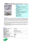
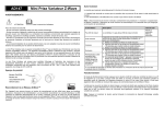
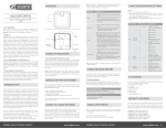
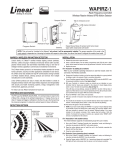
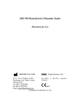
1
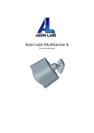
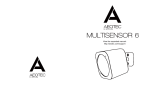
PSR04 Smart Color Button
This device is a multiple functions button switch. It is able to switch
the appliances on/off or adjust the percentage of dimmer. It can also
work as a timer. The well designed wall bracket and magnetic back
let the switch can be fixed on the wall. This product can be included
and operated in any Z-WaveTM network with other Z-WaveTM certified
devices from other manufacturers and/or other applications.
Note:
Please provide a 5 DVC voltage through Micro USB Port to
wake the device up before the first using.
The rotation function and timer functions work only when the device
is fitted upright or stick on the wall or the device will only work as
on/off switch when fitted horizontal.
Full Color LED 1
Red Light LED
Z-Wave Network Setting Up
Full Color LED 2
In the first time, add the device into the Z-WaveTM network. Make
sure the primary controller is in the add mode. And then power on
the device through micro USB. The device will auto start the NWI
(Network Wide Inclusion). Red LED will flash every second and
continue 30 seconds. And it should be included in 5 seconds. Red
LED will light ON one second. Rotating to area A(shown in Fig. 1)
and touch 3 times can abort NWI mode.
There is a touch button on the front side. The button carries out
manual inclusion, exclusion and reset to default.
1. Include: Pointing the arrowhead to area A first (shown in Fig. 1).
Pressing the button three times within 1.5 seconds. The red LED
will light up for 1 second if succeed.
2. Exclude: Pointing the arrowhead to area A first. Pressing the
button three times within 1.5 seconds.
3. Reset to default: Pointing the arrowhead to area A first. Pressing
button four times within 2 seconds and hold at fourth. The red
LED will light for 3 seconds, release the button within 2 seconds
while the LED goes out. The LED will flash for 1 second if reset
Touch Button
1
succeed, or LED will flash once.
area A(shown in Fig. 1). Rotate the device to area B, C, D(shown in
Fig. 1) then touch the button can set the status to On. After a short
beep, the surround LED will change gradually from blue to red in
area D. It will send Basic set command automatically 1 second after
rotating stop. To turn Off the device in group 2, you can rotate
PSR04 to area C or touch the button again.
Notice: Including a node ID allocated by Z-WaveTM Controller
means “Add” or “Inclusion”. Excluding a node ID allocated by ZWaveTM Controller means “Remove” or “Exclusion”.
Function
*Timer
This device can control dimmers in group 2 using three ways:
Dimmer, Timer, and On/Off Switch. Point the arrowhead to area
A(shown in Fig. 1 and Fig. 2) then hold the button, release after
the red LED go out. One beep means entering Timer mode or two
beeps means entering Dimmer mode. The device can switch to
On/Off Switch mode automatically when fitting horizontal.
*Dimmer
Figure 2
This mode can time the length of turning Off the light. The length is
up to 15 minutes. When counting down starts, surround LED will
flash and buzzer will sound according to the remaining time.
Rotating to area C can cancel counting down directly.
Figure 1
Note: Buzzer in timer mode can be disabled by setting
Configuration NO. 25 bit 1 to 1.
Figure 1
This device is able to set dimmer level by rotating to different
angle. When the status is Off, surround LED will not work except in
2
Timer left
Flash color
10~15 minutes
Cyan / 10 seconds
5~10 minutes
Green / 10 seconds
3~5 minutes
Yellow / 10 seconds
1~3 minutes
Orange / 10 seconds
30~60 seconds
Pink /10 seconds
10~30 seconds
Pink /10 seconds
1 beep / 10 seconds
1~5 seconds
Pink / 1 second
1 beep / 1 second
Time' up
White / 1 second
4 beeps / 1 second
• Battery level report: Every 6 hours report once in default.
It could be changed by setting the configuration NO. 10.
• Low battery report: When the battery level is too low, every 30
minutes will report once.
Buzzer
Z-WaveTM Notification
After the device adding to the network, it will wake-up once per day
in default. When it wake-up it will broadcast the “Wake Up Notification” message to the network, and wake-up 10 seconds for receive
the setting commands. The wake-up interval minimum setting is 30
minutes, and maximum setting is 120 hours. And the interval step is
30 minutes. If the user want to wake-up the device immediately,
please rotate to area A and pressing the touch button once. The device will wake-up for 10 seconds every single time.
*On/Off Switch
Configuration
This device is able to work as On/Off switch by sending Basic set
according to configuration NO.1 and NO.2 when fitting horizontal.
* The configuration mark with star(*), means after the
remove the setting still keep, don't reset to factory default.
Unless the user execute the “RESET” procedure.
NO. Name
Size Def. Valid
Description
(Byte)
Values
Association
This device supports 2 association groups which every group has
eight node support.
To build/disable association between devices,
1. Have the Z-Wave controller entered association mode.
2. Rotate PSR04 to area A then press the button three times within
1.5 seconds.
Group 1 is for receiving the report message, like the battery level.
Group 2 is for light control, the device will send Basic Set
command to this group.
1
2
Timing Report
The device supports the timing unsolicited report of the status.
3
Basic Set
OFF level
Basic Set
ON level
1
1
Control the value represented
by the left-side in area D.
0x00 0x00~0x63 E.g. Setting this configuration
to 0x0F means range of
Command Basic Set value
start from 0x0F
Control the value represented
by the right-side in area D.
0x63 0x00~0x63 E.g. Setting this configuration
to 0x1E means range of
Command Basic Set value
start from 0x1E
10
25
*26
Auto
Report
Battery
Time
Customer
Function
Disable
Scene
Holding
report
1
1
1
12
1~127
ond. Please don't remove the battery before the LED stop flashing.
Notice: recommend using OTA when the device is charging.
The interval time for auto reporting the Battery level. 0
means turn off auto report
battery.
The default value is 12.
Supported Z-Wave Command Classes
Bit 0: Dimmer setting
method.
0 : Auto send Command Basic Set after rotating.
1 : Send Command Basic Set
0x00 0x00~0x03 by touching key after rotating
Bit 1: Disable buzzer in timer
mode.
0: Enable.
1: Disable.
0x00
*
*
*
*
*
*
*
*
*
*
*
*
*
*
Send Central Scene Holding
0x00, 0x01 when the button is held.
0x00: Enable.
0x01: Disable.
Installation
COMMAND_CLASS_ZWAVEPLUS_INFO_V2
COMMAND_CLASS_BATTERY
COMMAND_CLASS_CENTRAL_SCENE_V1
COMMAND_CLASS_VERSION_V2
COMMAND_CLASS_MANUFACTURER_SPECIFIC_V2
COMMAND_CLASS_DEVICE_RESET_LOCALLY
COMMAND_CLASS_ASSOCIATION_V2
COMMAND_CLASS_WAKE_UP_V2
COMMAND_CLASS_ASSOCIATION_GRP_INFO
COMMAND_CLASS_POWERLEVEL
COMMAND_CLASS_MULTI_CMD
COMMAND_CLASS_SECURITY
COMMAND_CLASS_FIRMWARE_UPDATE_MD_V2
COMMAND_CLASS_CONFIGURATION
Security Network
1. Fix the bracket on the wall.
2. There's a magnet on the backside of this device. It can stick to
the bracket.
Notice: Do not install the bracket on unstable wall, this
may cause miscarriage to control lights.
The device support the security function. When the device included
with a security controller, the device will auto switch to the security
mode. In the security mode, the follow commands need using
Security CC wrapped to communicate, otherwise it will not response.
COMMAND_CLASS_BATTERY
COMMAND_CLASS_ASSOCIATION_V2
COMMAND_CLASS_CONFIGURATION
COMMAND_CLASS_WAKE_UP_V2
COMMAND_CLASS_CENTRAL_SCENE
Firmware update over the air (OTA)
This device supports the Z-Wave firmware update via OTA. Let the
controller into the firmware update mode, and rotate to area A
then touch the button once to start update. After finish the
firmware download, the red LED will start to flash every 0.5 sec4
Troubleshooting
Specification
Symptom
Cause of Failure Recommendation
The switch on/off
1. Battery is
1. Charging the battery by
function not working running out of
Micro USB.
and LED off
power
2. Pointing the arrowhead
2. Wrong function
to area B and press the
mode
touch button.
3. If the device still can
work, don’t open up the
Switch and send it for
repair.
Can not adjust the 1. The device may 1. Check if the device is
percentage of
not be placed
placed upright.
dimmer
upright.
2. Rotating to the
2. The device is in
percentage you want
off state.
then press touch button.
Or pointing the
arrowhead to area B and
press the touch button
to turn the lamp on then
adjust the percentage.
The device can not 1. The device may 1. Exclude the device then
join to Z-Wave
in a Z-Wave
include again.
network
network.
2. Pointing the arrowhead
2. The arrowhead
to area A then include
points to wrong
again.
area.
Button no response 1. The button will Wait for the LED go out
no response
and try again.
when LED is
flashing.
Operating
Voltage
Battery Charge
Voltage
Range
3.7 V (Lithium Polymer Battery)
5 VDV @ Micro USB Port
Minimum 40 m in door, 100m outdoor line of
sight
-10°C ~ 40°C
Operating
Temperature
Frequency Range PSR04-1: 868.40MHz; 869.85MHz(EU) /
PSR04-2: 908.40MHz; 916.00MHz(USA/Canada) /
PSR04-3: 922.5MHz/ 923.9MHz/ 926.3MHz
(Taiwan/JP)
** Specifications are subject to change and improvement without
notice.
FCC ID : RHHPSR04
Disposal
This marking indicates that this product should not be
disposed with other household wastes throughout the EU.
To prevent possible harm to the environment or human
health from uncontrolled waste disposal, recycle it
responsibly to promote the sustainable reuse of material
resources. To return your used device, please use the
return and collection systems or contact the retailer where
the product was purchased. They can take this product for
environmental safe recycling.
Company of License Holder:Philio Technology Corporation
Address of License Holder:8F.,No.653-2,Zhongzheng Rd.,
5
Xinzhuang Dist., New Taipei City 24257,Taiwan(R.O.C)
is encouraged to try to correct the interference by one of the following measures:
• Reorient or relocate the receiving antenna.
• Increase the separation between the equipment and receiver.
• Connect the equipment into an outlet on a circuit different from
that to which the receiver is connected.
• Consult the dealer or an experienced radio/TV technician for help.
This device complies with Part 15 of the FCC Rules. Operation is
subject
to the following two conditions:
(1) This device may not cause harmful interference, and
(2) This device must accept any interference received, including interference that may cause undesired operation.
FCC Caution: Any changes or modifications not expressly approved
by the party responsible for compliance could void the user's authority to operate this equipment.
This transmitter must not be co-located or operating in conjunction
with any other antenna or transmitter.
FCC Interference Statement
This equipment has been tested and found to comply with the limits for a Class B digital device, pursuant to Part 15 of the FCC
Rules.
These limits are designed to provide reasonable protection against
harmful interference in a residential installation.
This equipment generates, uses and can radiate radio frequency
energy and, if not installed and used in accordance with the instructions, may cause harmful interference to
radio communications.
However, there is no guarantee that interference will not occur in a
particular installation.
If this equipment does cause harmful interference to radio or television reception, which
can be determined by turning the equipment off and on, the user
6