1
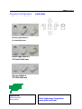
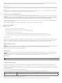
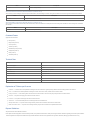
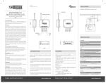
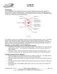
PAN11-1/-2/-3
Smart Energy Plug-in Switch
Z-Wave Series
Features
Adopt Z-Wave protocol to secure the success of wireless two
way communication
Higher RF output power (+2.5dBm output power as compared to
-2.5dBm 300 series Z-wave module) to enhance the
communication range
With zero crossing technology to extend the number of switching
Easy install
Very low Electricity consumption ,
Resistive load 3000W, 1500W for incandescent load or 320W for
fluorescent load
Overload protection
Auto report the state when manually push the ON/OFF button
Auto report the wattage when variation over 5%
Voltage, Current, Power factor, Instant power Wattage and
Accumulated power consumption KWh report
Z-Wave V6.02
Z-Wave Certificated
PAN11-1 ZC08-13020005
PAN11-2 ZC08-13020006
PAN11-3 ZC08-13020007
LVD:EN 61058
R&TTE : EN 301489, EN 300200,
Introduction
This smart energy plug-in switch is a transceiver which is a Z-WaveTM enabled device and is fully compatible with any Z-WaveTM
enabled network. Z-WaveTM enabled devices displaying the Z-WaveTM logo can also be used with it regardless of the manufacturer,
and ours can also be used in other manufacturer’s Z-WaveTM enabled networks. Remote On/Off control of the connected load is
possible with other manufacturer’s Wireless Controller. Each switch is designed to act as a repeater. Repeaters will re-transmit the
RF signal to ensure that the signal is received by its intended destination by routing the signal around obstacles and radio dead
spots.
This smart energy plug-in switch is able to detect voltage, current, power factor, Instant power wattage (5~3150W) and overload
wattage (3010~3300W) of connected light or appliances. When detecting overload state, the Module will be disabled and its On/Off
button will be lockout of which LED will flash quickly for 30 seconds. However, unplug and re-connect the Module will reset its
overload condition to normal status.
This plug-in switch can active sent out instant power wattage when variation over 5% or active sent out state change when
manually push the ON/OFF button , this allows the controller to avoid polling the reading wattage value and state of the switch and
can increase the efficiency of controller.
Specification
Power
No load standby power
Input voltage
0.48W (230V)
90 ~240VAC
RF
Frequency
Regulation
Distance
weight
Dimension (W x H x D)
868.42 (EU) MHz
FCC part15.249 / EN300 220-1/
min. 30m indoor min. 100m outdoor
118 g
57.7x94.5x76.6 mm (Germany type PAN11-1)
Operation Temperature
Humidity
Resistive load
incandescent load
fluorescent load
load return error rate 5W~40W
load return error rate40W~3150W
overload
0 ~ 40° C
85%RH max
3000W
1500W
320W
±3W
±5%
3300W
Mechanical
Environment
Load
1
PAN11-1/-2/-3
Dimension and Placement
unit:mm
unit :mm
(unit:mm)
Germany type PAN11-1
57.7x94.5x76.6 mm
France type PAN11-2
57.7x94.5x76.6 mm
UK type PAN11-3
57.7x94.5x61 mm
Application:
Home Automation
Energy Saving
Philio Technology Corporation
www.philio-tech.com
2
PHI_PAN11
Z-Wave Schuko Plug-in Switch plus Power Meter
Firmware Version : 1.1
Quick Start
A
This device is a Z-Wave Actor. Tripple click the button on the device confirms the inclusion, exclusion and association. After plugging in it will stay in auto inclusion mode for 4 minutes.
Please refer to the chapters below for detailed information about all aspects of the products usage.
What is Z-Wave?
This device is equipped with wireless communication complying to the Z-Wave standard. Z-Wave is the inte rnational standard for w ire le ss com m unication in smart homes and
buildings. It is using the fre que ncy of 868.42 MHz to realize a very stable and secure communication. Each message is reconfirmed (tw o-w ay com m unication) and every mains powered
node can act as a repeater for other nodes (m e she d ne tw ork) in case the receiver is not in direct wireless range of the transmitter.
Z-Wave differentiates between Controllers and Slaves. Slaves are either sensors (S) transmitting metered or measured data or actuators (A) capable to execute an action. Controllers are either
static mains powered controllers (C) also referred to as gateways or mobile battery operated remote controls (R). This results in a number of possible communication patterns within a Z-Wave
network that are partly or completely supported by a specific device.
1.
2.
3.
4.
5.
6.
7.
Controllers control actuators
Actuators report change of status back to controller
Sensors report change of status of measured values to controller
Sensors directly control actuators
Actuators control other actuators
Remote controls send signals to static controllers to trigger scenes or other actions
Remote controls control other actuators.
There are two different role a controller can have. There is always one single primary controller that is managing the network and including/excluding devices.
The controller may have other functions - like control buttons - as well. All other controllers don't manage the network itself but can control other devices. They
are called secondary controllers. The image also shows that its not possible to operate a sensor just from a remote control. Sensors only communicate with static
controllers.
Product description
The PAN11 is a Plug-in switch, which can be placed between a wall outlet for Schuko plug and electric devices with a resistive load up to 3000W, plugged in by cord. In addition, this
intelligent plug-in switch is able to detect the voltage, the power factor, the current amd measure the electric power taken by this load (in Wh) as well as meter the electrical energy
consumed (in kWh). It will also detect a possible overload (3010 ~ 3300W) of the connected electrical device. When detecting an overload, the module is deactivated and the LED will flash for
30 seconds.
Before Device is installed
Please read carefully the enclosed user manual before installation of the radio-actuator, in order to ensure an error-free functioning.
ATTENTION: only authorized technicians under consideration of the country-specific installation guidelines/norms may do works with 230 Volt mains power. Prior to the assembly of the
product, the voltage network has to be switched off and ensured against re-switching.
The product is permitted only for proper use as specified in the user manual. Any kind of guarantee claim has to be forfeited if changes, modifications or painting are undertaken. The product
must be checked for damages immediately after unpacking. In the case of damages, the product must not be operated in any case. If a danger-free operation of the equipment cannot be
assured, the voltage supply has to be interrupted immediately and the equipment has to be protected from unintended operation.
Installation Guidelines
In the front casing there is an On/Off button with LED indicator, which is used to toggle switch on and off or carry out inclusion, exclusion, reset or association. When first powered, the LED
flashes on and off alternately at a 2-seconds interval. It implies that it is not included in a Z-Wave network and has not been assigned a node ID.
Auto Inclusion
The auto inclusion starts when the switch is not included into a Z-Wave network and plugged into a wall outlet. Auto inclusion timeout is 4 minutes during the node information frame will be
emitted once every 5 seconds. Unlike the normal inclusion it is not necessary pressing the On/Off button on the switch. If auto inclusion exceeds the timeout you have to include the device
manually.
Note : Do not locate the switch facing direct sunlight, humid or dusty places. The suitable ambient temperature for the switch is 0°C - 40°C. Do not locate the switch near to combustible
substances or any source of heat. After putting it into use, the casing of the switch will become a little bit warm.
Behavior within the Z-Wave network
I
On factory default the device does not belong to any Z-Wave network. The device needs to join an existing wireless network to communicate with the devices of this network. This
process is called Inclusion. Devices can also leave a network. This process is called Exclusion. Both processes are initiated by the primary controller of the Z-Wave network. This controller
will be turned into exclusion respective inclusion mode. Please refer to your primary controllers manual on how to turn your controller into inclusion or exclusion mode. Only if the primary
controller is in inclusion or exclusion mode, this device can join or leave the network. Leaving the network - i.e. being excluded - sets the device back to factory default.
If the device already belongs to a network, follow the exclusion process before including it in your network. Otherwise inclusion of this device will fail. If the controller being included was a
primary controller, it has to be reset first.
Tripple Click the button on the device confirms inclusion and exclusion. After plugging in it will stay in auto inclusion mode for 4 minutes.
Operating the device
Manual Ope ration
Plug the device into a wall outlet near the load to be controlled.
Plug the load into the switch. Make sure the load to be controlled cannot exceed 3000 watts.
Press the button or switch the load to the ON position.
To manually turn ON the switch, press and release the On/Off button. The LED will turn on, and the load plugged into the switch will also turn on.
To manually turn OFF the switch, simply press and release the On/Off button again. The LED will turn off and the load plugged into the switch will also turn off.
Re m ote Ope ration
Remote On/Off control of the switch is possible with any manufacturer's Z-Wave controller. Further you can set associations to let your device controlled by other Z-Wave devices like sensors.
The switch is able to detect the current wattage (5 - 3150W) and overload wattage (3010 - 3300W) of connected ligths or appliances. When detecting overload state, the switch will be
disabled and its On/off button will be locked and the LED will flash quickly. However unplug and reconnect the switch to reset its overload condition to normal status.
Node Information Frame
NI
The Node Information Frame is the business card of a Z-Wave device. It contains information about the device type and the technical capabilities. The inclusion and exclusion of the
device is confirmed by sending out a Node Information Frame. Beside this it may be needed for certain network operations to send out a Node Information Frame.
Tripple click the button on the device sends out a Node Information Frame.
Associations
A
Z-Wave devices control other Z-Wave devices. The relationship between one device controlling another device is called association. In order to control a different device, the
controlling device needs to maintain a list of devices that will receive controlling commands. These lists are called association groups and they are always related to certain events (e.g.
button pressed, sensor triggers, ...). In case the event happens all devices stored in the respective association group will receive a common wireless command.
Association Groups:
1 When the power consumption of load vary over 5%, the PAN11 will send a Meter Report. When "on" or "off" state has been changed, it will send Binary Switch Report. (max. nodes in group: 1)
Configuration Parameters
Z-Wave products are supposed to work out of the box after inclusion, however certain configuration can adapt the function better to user needs or unlock further enhanced features.
IMPORTANT: Controllers may only allow to configure signed values. In order to set values in the range 128 … 255 the value sent in the application shall be the desired value minus 256. For
example: to set a parameter to 200 it may be needed to set a value of 200 minus 256 = minus 56. In case of two byte value the same logic applies: Values greater than 32768 may needed to
be given as negative values too.
Watt Me te r Re port Pe riod (Param e te r Num be r 1, Param e te r Size 2)
If the setting is configured for 1hour (set value =720), the PAN11 will report its instant power consumption every 1 hour to Z-Wave Controller. Unit: 5 seconds
Value
1 — 32767
D e scription
720 * 5s = 3600s = 1 hour (Default 720)
KWH Me te r Re port Pe riod (Param e te r Num be r 2, Param e te r Size 2)
If the setting is configured for 1hour (set value =6), the PAN11 will report its Accumulated Power Consumption (KW/h) every hour to Z-Wave Controller. Unit: 10min
Value
D e scription
1 — 32767
6 * 10min = 1hour (Default 6)
Thre shold of Watt for Load caution (Param e te r Num be r 3, Param e te r Size 2)
This is a warning when the wattage of load over the preset threshold value, if the load wattage exceeds the setting value the PAN11 will send a warning alarm command to the controller.
Value
10 — 3000
D e scription
wattage threshold value (Default 3000)
Thre shold of KWh for Load caution (Param e te r Num be r 4, Param e te r Size 2)
This is a warning when the KWh of load over the preset threshold value, if the Accumulated Power Consumption exceeds the setting value the PAN11 will send a warning alarm command to
the controller.
Value
1 — 10000
D e scription
KWh threshold value (Default 10000)
Command Classes
Supported Command Classes
Basic (version 1)
Binary Switch (version 1)
Version (version 1)
All Switch (version 1)
Manufacturer Specific (version 2)
Configuration (version 1)
Meter (version 3)
Association (version 1)
Technical Data
IP Rating
IP20
Explorer Frame Support
Yes
SDK
6.02.00
Device Type
Slave with routing capabilities
Generic Device Class
Binary Switch
Specific Device Class
Binary Power Switch
Routing
Yes
FLiRS
No
Firmware Version
1.1
Explanation of Z-Wave specific terms
Controlle r — is a Z-Wave device with capabilities to manage the network. Controllers are typically Gateways, Remote Controls or battery operated wall controllers.
Slave — is a Z-Wave device without capabilities to manage the network. Slaves can be sensors, actuators and even remote controls.
Prim ary Controlle r — is the central organizer of the network. It must be a controller. There can be only one primary controller in a Z-Wave network.
Inclusion — is the process of bringing new Z-Wave devices into a network.
Exclusion — is the process of removing Z-Wave devices from the network.
Association — is a control relationship between a controlling device and a controlled device.
Wake up Notification — is a special wireless message issued by a Z-Wave device to annonces that is is able to communicate.
Node Inform ation Fram e — is a special wireless message issued by a Z_Wave device to announce its capabilities and functions.
Disposal Guidelines
The product does not contain hazardous chemicals.
Do not dispose of electrical appliances as unsorted municipal waste, use separate collection facilities. Contact your local government for information regarding the collection systems available.
If electrical appliances are disposed of in landfills or dumps, hazardous substances can leak into the groundwater and get into the food chain, damaging your health and well-being.