1
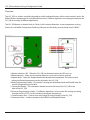
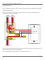
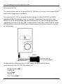
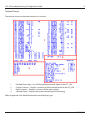
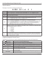
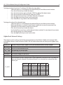
REVISION 1
FORM # WW07-709
INSTALLATION, WIRING & CONFIGURATION
LVS_250
(Wireless Baseboard Controller)
BUILDING INTELLIGENCE WORLDWIDE
LVS_250 Installation, Wiring & Configuration Guide
1
Overview
The LVS_250 is a wireless controller designed to switch baseboard heaters within a mesh network, and is the
Walker Wireless replacement for a baseboard thermostat. Different algorithms can be programmed into the
LVS_250 for a variety of different applications.
The LVS_250 features a setpoint knob in Celsius, built in motion detection, a room temperature sensing
thermistor with Walker Temperature Predicting Software and the ability to control and switch 240VAC.
Features
4
1
5
2
8
6
3
7
Front
Back
1.Motion indication LED – When the LVS_250 has detected motion the LED turns on.
2.Motion detector – Make sure the motion detector is never obstructed or covered.
3.Setpoint Knob – Adjust the Setpoint Knob to the desired room temperature. The minimum and
maximum allowed temperature can be adjusted in the LVS_250.
4.Radio Programming Header – This header is to program the onboard radio and should never be
used for programming in the field.
5. Connection Header – This connection header connects the front of the LVS_250 to the back of the LVS_250.
6.Processor Programming Header – If a different algorithm is to be used or the settings are being changed via Easy-TOOL, use this header to reprogram the processor.
7.Communication Port – Used to view and change all settings locally in the LVS_250.
8.Connection Wires – Used to connect to the 240VAC and Baseboard heater.
WW07-709
LVS_250 Installation, Wiring & Configuration Guide
2
Motion Detector
The built in motion detector allows the LVS_250 to turn down the Setpoint when no bodies are detected in
the zone. The motion detector has a range of 10 meters at a viewing angle of 150 degrees.
Below are the objects pertaining to the motion detector:
TM_MOTN
Is the amount of time in minutes to wait after no motion is detected before changing the Setpoint to
unoccupied.
ST_NO_M
The heating Setpoint to control to when the TM_MOTN time has expired and the LVS_250 goes into
unoccupied mode.
When motion is detected, the LVS_250 will revert back to the knob Setpoint for control. When no motion is
detected for the specified time the LVS_250 will go into unoccupied mode.
Make sure not to block or limit the vision of the motion detector. If the motion detector can not see motion
it will always control to the no motion setpoint (ST_NO_M).
WW07-709
LVS_250 Installation, Wiring & Configuration Guide
3
Power Requirements
The LVS_250 powers and switches 240VAC and draws a maximum of 200mA to operate when fully loaded.
Hardware Configuration
The LVS_250 is made to directly replace a mechanical thermostat controlling a baseboard heater. The
LVS_250 is to be wired in as shown below.
240VAC
240VAC
Power In Power Out
To Heater(s)
The 2 line wires from the back of the LVS_250 connect to the 240VAC supply lines from the breaker box. The
Load lines are connected to the baseboard heater(s).
The LVS_250 is capable of switching 240VAC at a maximum 10A of current.
WW07-709
LVS_250 Installation, Wiring & Configuration Guide
4
Software Configuration
Easy-TOOL
To connect the Atmel AVRISP mkII programming dongle to the LVS_250, connect the ribbon cable header
from the AVRISP mkII to the LVS_250s processor programming header as shown in the picture below. If
corrected correctly the LED on the AVRISP mkII will turn green. Please see the Easy-TOOL user guide on how
to program through the Atmel AVRISP mkII.
WW07-709
LVS_250 Installation, Wiring & Configuration Guide
5
Communication Port
The communication port on the base of the LVS_250 allows all settings to be changed locally
via a terminal program on a computer.
To connect the LVS_250 to a computer for local changes a Cable-ROOMSTAT and DB9F6
(Both from Walker Technologies Corp.) are required. Connect the 3-pin end of the CableROOMSTAT to the communication port on the base of the LVS_250 with the painted white
strip facing the corner of the LVS_250. Connect the RJ12 end of the Cable-ROOMSTAT to the
DB9F6 and then connect the DB9F6 to an available comm. port on the computer or an USB
to Serial adapter.
DB9F6
Cable-ROOMSTAT
To comm. port or
USB to serial adapter
The appropriate settings must be set in the terminal program used for proper
communication to the LVS_250. The settings are:
-
-
-
-
-
Bits per Second: 9600
Data bits: 8
Parity: None
Stop Bits: 1
Flow Control: None
WW07-709
LVS_250 Installation, Wiring & Configuration Guide
6
Terminal Screen
The terminal screen can be broken down into 4 sections:
1
4
3
1.
2.
3.
4.
2
Detailed Object data – Lists all information about each object in the LVS_250
Control Overview – Displays a summary of all the control points for the LVS_250
Radio Overview – Displays a summary of the radio settings
Selected Object – Displays the current selected object for changing
Refer to Appendix A for detailed information on each object type.
WW07-709
LVS_250 Installation, Wiring & Configuration Guide
7
Object Breakdown
Each object is listed with an abundance of information.
10
s
USED_HT
25.0
A
L
emlt
V2
0
Object number.
If there is a lower case “s” the object can be commanded in GCL, if it is mapped to a point.
The name of the object.
The current value of the object.
Displays if the object is in control by software (Auto “A”) or has been set by a user (Manual “M”).
If an “L” is displayed the objects value was written by the firmware in the LVS_250.
If an “S” is displayed the objects value was written by GCL.
If an “e” is displayed SUPEREANBLE is on and allows GCL to command the object.
If an “m” is displayed SUPERMANUAL is on and the object can be commanded in manual mode.
If an “l” is displayed SUPERLOCAL is on and GCL is able to command objects displaying “L”.
If a “t” is displayed TIMEDMANUAL is on and the point will revert to auto after the time set in
EC_T_SUPER expires when command to manual (Physical Outputs only).
The point the object will be mapped to in the Walker System. Displayed by a single letter (point
type) followed by the point number (0-9).
V – VA point
C – VC point
F – VF point
I – IP point
O – OP point
Count down timer. If the object was command by GCL or a Physical Output was command to
manual, this displays the time left in minutes until the command is overwritten by the pervious
value. Time is set in EC_T_SUPER.
Navigating Through the Terminal Screen
The keyboard and arrow keys are used to navigate through the terminal screen and change objects.
(Left Arrow)
(Right Arrow)
(Up/Down Arrows)
(Enter/Return)
“Q”
“W”
“N”
Other Letters
Used to select the current displayed object.
Used to set the current setting to the selected object.
Scroll through objects and change values on selected objects.
Cancel the change to an object or return to the object from its status menu.
Writes settings to the radio.
Reads the settings from the radio.
Causes the radio to dump its Channel and Operational PAN ID and search for
the network again.
Pressing a letter other than the 3 listed above will cycle through objects
starting with that letter.
WW07-709
LVS_250 Installation, Wiring & Configuration Guide
8
To change an object from Auto “A” to Manual “M” follow the steps below:
-
Select the object so it is displayed in the Selected Object area of the terminal window.
-
Press the Left arrow key to select the object.
-
Press the Left arrow key again to display “STATUS” in place of the object name.
-
Press the Left arrow for a third time to select the “STATUS”
-
Press the Up/Down arrow keys until “Man” (Manual) is displayed
-
Press the Right arrow key to enter set the command.
-
Press Enter/Return to go back to the selected object.
To change the value of the selected object:
-
Select the object so it is displayed in the Selected Object area of the terminal window.
-
Make sure the point is in manual. Not all objects need to be in manual to command. See Appendix A for which objects need to be in manual.
-
Press the Left arrow key to select the object.
-
Use the Up/Down arrow keys until the desired value is reached. Or some objects let you enter the value by typing it in on the keyboard.
-
Press the Right arrow key to enter set the value.
ZigBee Mesh Network Settings
These objects are the settings required for communication over the Wireless ZigBee mesh network. Refer
to the Walker Wireless Setup Document (WW01-709) for further information on setting up the ZigBee mesh
network.
DEST_HI
The top 32bits of the MAC address. Set to the destination device (usually Zcoord)
DEST_LW The bottom 32 bits of the MAC address. Set to the destination device (usually Zcoord)
SET_PAN The PAN ID of he network to join.
MY__PAN The read PAN ID from the radio.
SAC_ADR The MicroSAC address the data is to be sent to.
ADDRESS The wireless address of the device.
TIMESAC Set to the MicroSAC address that is sending out the time.
Set the channels to scan. Each bit of the 2 bytes represents a channel to scan. The radio will
only scan channels selected. If the desired network is on a channel not scanned the radio
will not join.
ST_ATSC
Channel
Bit
Channel
Bit
Channel
Bit
B
0
11
6
17
12
C
1
12
7
18
13
D
2
13
8
19
14
E
3
14
9
1A
15
F
4
15
10
10
5
16
11
I.e. to scan all channels set to FFFF. To on scan 1A set to 8000.
WW07-709