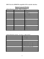
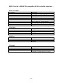
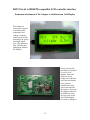
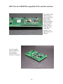
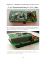
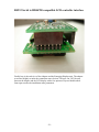
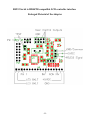
1
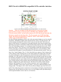
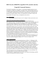
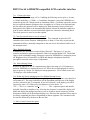
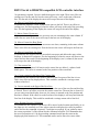
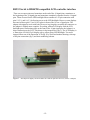
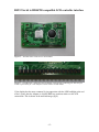
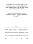
RS232 Serial to HD44780 compatible LCD controller interface
USER MANUAL
Adapter Version V1A, V1B - Software V1.2.1
Congratulations on your purchase!
Before connection or power up please read the quick start guide.
Through out this manual the RS232 to HD44780 compatible LCD controller interface is
referred to as simply the “Adapter”
Page
INDEX
Index
1
Quick Start Guide
2
Command Summary
3
Expanded Command Summary
4
User Created Characters
9
Settings Retained at Power Down
10
Settings Reset During “Test” mode
10
Hardware Description
11
The Adapter Pin Outs
15
Adapter attached to Datavision 2x16 Display
17
The Adapter and an Emerging Displays SPC 1 94V LCD Display
20
Enlarged Pictorial of the Adapter
22
Revisions, changes
23
-1-
RS232 Serial to HD44780 compatible LCD controller interface
QUICK START GUIDE
Interface board shown component side up. Larger image at rear of this manual.
Caution - Please be extremely careful that your power connections are made
properly. Reverse power or incorrect power will likely cause immediate failure.
Note the location of PIN 1 of the 18 pin connector it is NOT the first pin but rather the
third pin as noted in the drawing above. The first two pins are for LED backlight
supply. On the three pin input/power connector “GND” is the common for both the
+5dvdc supply and the RS232 signal.
For those having used adapters such as this in the past much of what you see here should
be intuitive. Most RS232 signals from microprocessors will be TTL non-inverted. The
enclosed jumper should then be between the center post and the NON INVerted pin
shown in the drawing. If connecting to a personal computer most often the signal needs
INVerting, the jumper would then be from the INVerting terminal to the center terminal.
This is the only jumper required. For testing the jumper can be placed across the TEST
pins (shown above). This will cause a reset of parameters within the microprocessor as
well as generating a continuous string of repeating characters across the display. TEST
continues until the jumper is removed and power is disconnected and restored. There are
three User Control Outputs. Pins 1-3 of the 8 pin dual row connector. Pin 8 (bottom left
of the connector in the drawing above) is the return path for the Output Pins. Note these
are connected directly to the microprocessor and are therefore current limited to a few
milliamps. An LED could be controlled directly but not such high current items as relays.
For software commands if you have used the P.H. Anderson pic controller you will find
the commands used here very similar and in many applications find little modification of
your existing software will be needed, removal of time delays being most common. The
adapter is shipped in the 4x20 display mode, 9600 baud, 8 bit mode, medium display
intensity and heartbeat LED on. Any of these parameters can be easily changed via
software commands. Some require a power down - power up to adapt the display to the
changes made. The adapter can be used with most known display types from 1x6 to the
4x20. If the addressing remains consistent across the display, the display should function.
Displays that will not function are those one or two line displays with split addressing or
a non-sequential address on the same row of characters.
-2-
RS232 Serial to HD44780 compatible LCD controller interface
COMMAND SUMMARY
COMMANDS
ENTER
?a
Home Cursor
?Gyxx LCD row(y) and column(xx) configuration
Change baud 1=300, 2=1200, 3=2400, 4=9600,
?vmvx 5=19200 (change is immediate)
Cursor style x=0 none, =1 blink+underline, =2 blink,
?cx
=3 underline.
?f
Clear Screen and cursor to row 0 column 0
?Bxx Set Backlight intensity hex 01 to FF, 01=dark
Select screen visible at turn on 0=blank,
?Sx
1=default/config and 2=user defined
Define a line of user screen, characters should be equal
to row defined in ?Gyxx above, pad with spaces if
needed.
Columns equal to columns defined in ?Gyxx starting
?Cx
with column 0.
?i
Move cursor forward
?h
Move cursor backward
?j
Move cursor to same column one row up
?k
Move cursor to same column one row down
Move cursor one space left and empty that space.
?b
Destructive backspace.
?l
Clears current line
?m
Cursor to start of current line – carriage return
?n
Cursor to start of next line, that line cleared
Move cursor to xx position starts with zero and two
?xxx
digits are required.
?yx
Move cursor to y row, y starts with zero
?sx
Set tab at x position, one digit allowed
?t
Move to tab position, current line no wrap
?Dx
?R
?Hx
?Lx
?Zx
?Ix
??
Define custom characters, x is character (0-7)
Reload custom characters – used after a change
Take user output pin to high level x=1,2 or 3
Take user output pin to a low level x=1,2,or 3
Toggles the heartbeat LED on/off x=1= on, all else off
Selects LCD Interface x=4= 4bit, all else 8 bit
Sends a question mark? to the display
Multiple commands are acceptable
-3-
EXAMPLE
“?a”
“G420” or “G106”
“vmv3” =2400 baud
“?c0” = no cursor
“?f”
“?B80” = medium
“?S2” = defined screen
“?C0 This is a line “
“?i”
“?h”
“?j”
“?k”
“?b”
“?l”
“?m”
“?n”
“?x05”
“?y1”
“?x5”
“?t”
“?D0000a00110e000000”
creates a smiley face
“?R”
“?H3”
“?L3”
“?Z1”
?I4”
“??”
“?y2?x05Hello World?n”
RS232 Serial to HD44780 compatible LCD controller interface
Expanded Command Summary
Note that all commands are case sensitive. As well some commands must have two or
more digits to complete the command. An example of this is ?Bxx backlight intensity. A
two digit response along with the ?B entry characters is required. If the response desired
is 6, for instance, than 06 must be used. Failure to respond correctly will in some cases
generate an unwanted response. There is no requirement for wait states or delays with
any command. Wait states, if any, are transparent to the end user.
?a
Home Cursor
This command returns the cursor to row 0, column 0. It does not clear the screen.
?Gyxx LCD row(y) and column(xx) configuration
This command sets the size of the display tracked and handled by the
microcontroller software. This command requires in addition to the command prompt and
G one digit representing the number of rows, up to 4 and two digits representing the
number of columns. Parameter is stored in EEPROM so is retained at power off. The
default display size is 4x20. If the test mode is entered the adapter will be returned to this
4x20 default. Displays from 1x6 to 4x20 have been tested and found functional. Some
displays have non contiguous addressing on one line and will not function correctly. Non
contiguous addressing is expected on multi line displays and handled transparently by the
microcontroller software. Since display size is a software issue it does not matter the size
selected. For instance, if needed, you could set a 4x20 physical size display for say 2x10.
The data would then be displayed in a 2x10 window contained within the 4x20 display.
Selecting a display size larger than the actual size will cause characters to be invisible as
some would be displayed outside the physical viewing area.
A common error is to enter this command as ?G2x16. This will cause the display size to
be 2 rows 1 column wide. Re-entering the command correctly ?G216 will immediately
correct the situation changing the display size to 2 rows by 16 columns wide.
?vmvx Change baud rate
x is an integer from 1 to 5 representing the baud rates as follows: 1=300 baud, 2=1200
baud, 3=2400 baud, 4=9600 baud, 5=19200 baud. Parameter is stored in EEPROM so is
retained at power off. The changes made are immediate. Your software will have to
change its rate as soon as the command is entered or your data will not be displayed
properly. At some point you may select and program a rate only to become confused as to
what has happened. There are two ways to maneuver out of this situation. The first is to
power down, then up the adapter/LCD display. During startup with the normal logo
screen the currently selected baud rate is displayed. Failing this another possibility is to
power down the adapter/LCD combination and insert a jumper across the test terminals.
This will cause the processor software to do an initialization to its stored defaults. This
causes the adapter to revert to its default baud rate of 9600.
The flexibility of a changeable baud rate was felt to outweigh the disadvantages possibly
created by allowing software baud rate changes.
-4-
RS232 Serial to HD44780 compatible LCD controller interface
?cx Cursor style select.
X is a single digit in the range of 0 to 3 enabling the following cursor styles, x=0 none,
x=1 blink+underline, x =2 blink, x =3 underline. Parameter is stored in EEPROM so is
retained at power off. Changes made are immediate. Blink + Underline causes the current
but yet to placed character position to have its eighth row of 5 dots to be blackened and
the area where the character will be displayed to flash alternately between black and
background color. Blink is the alternating black block without the underline eighth row.
And of course underline is just the blackened eighth row without the alternating block.
The whole process is easier to see than explain.
?f Clear Screen and cursor to row 0 column 0
This command has no options and is immediate. This command invokes the LCD
controllers clear screen function. Although there is about a 1.5ms delay to process this
command the delay is normally transparent to the user due to the software buffer size of
the microprocessor.
?Bxx Backlight Intensity
In addition to the ?B requires two hex digits 0-Fand 0-F. The letters A_F are case
sensitive and must be uppercase characters. Dark is 00 and full bright is FF. The default
value is 0x80 a midrange setting. Parameter is stored in EEPROM so is retained at power
off. Brightness level is controlled via PWM and changes in brightness should be
perceptible across the entire scope of adjustment.
?Sx Select Startup Screen
Requires in addition to the ?S a single numeric digit in the range of 0-2. Parameter is
stored in EEPROM so is retained at power off. This is the screen displayed for a short
time on power up. Screen ?S1 display the startup parameters. ?S0 is a blank screen and
?S1 displays a user defined screen.
?Cx Define the line(s) making up the User Defined Startup Screen
Requires in addition to the ?C at least a single digit representing the line to be edited 0 to
a maximum of 3. The entry needed here will be dependant upon the size of the display
you have selected in the ?G command. If you have selected a 1x40 display you will be
expected to enter a ?C0 followed by 40 characters of your choice. I.e.
bbbbbbbThisb
b isb
b ab
b controllerb
b test! bbbbbbbbbbbbbbbbbbbb The bb represent spaces and must be
?C0b
included if needed to complete a line. After the last character is entered the display will
blank and display the changed user line as well as all others stored in memory (at least
that portion which will fit the defined display size). If desired the command can be sent in
its entirety command plus data or fragmented in shorter segments. The command could
be sent first followed by the data on the next line.
?i Move Cursor Forward one space
-5-
RS232 Serial to HD44780 compatible LCD controller interface
No parameters required. Cursor is shifted one space to the right. There is no effect on
existing test. If at the end of a line the cursor will wrap – move to the start of the next
line. If at the end of the display the cursor will wrap to the start of the display.
?h Moves Cursor Backward one space
No parameters required. Cursor is shifted one space to the left. There is no effect on
existing text. If at the beginning of a line the cursor will wrap to the end of the preceding
line. If at the beginning of the display the cursor will wrap to the end of the display.
?j Moves Cursor Up one row
No parameters are required. Moves cursor up one row remaining in the same column. If
at the first row (row 0) the cursor will wrap to the last row of the display.
?k Moves Cursor One Row Down
No parameters are required. Moves cursor one row down, remaining in the same column.
There is no effect on existing text. If on the last row the cursor will wrap to the first row.
?b Moves Cursor Back One Space
No parameters are required. Moves cursor back one space and deletes the entry at that
location. A destructive backspace. If at the beginning of a line the cursor will move to the
end of the line above and if at the beginning of the display (row 0, column 0) the cursor
will wrap to the end of the display.
?l Clear current line
No parameters are required. All entries on the cursor line are deleted – replaced with
blank spaces. The cursor is returned to the first position of the erased line.
?m Cursor returned to the Start of the Current Line
No parameters are required. The cursor is moved to the first space of the line it is on.
There is no effect on any displayed text. This would be considered a carriage return
without a line feed.
?n Cursor returned to the Start of the Next Line
No parameters are required. The cursor is moved to the start of the next line and that line
is cleared. There is no effect on text in the current cursor line. The next line is cleared. If
you are using a one line display, however, the cursor is returned to the first position and
that line is cleared. If the cursor is on the last line of the display it will wrap and clear the
first line of the display. This would be considered a carriage return with a line feed.
?xxx Position Cursor to Column xx
Two parameters are required. The cursor will be moved to the location specified by xx on
the same row it is currently on. If the values entered would place the cursor beyond the
end of the line the command is ignored. Two digits are required. If you wished to move
the cursor to position 5 of the current line the command would be ?x05 Remember that
the rows first position is 0. So the preceding command would put the cursor at the
displays physical location of 6. This command can be used to move the cursor either
-6-
RS232 Serial to HD44780 compatible LCD controller interface
forward or backward as long as the command would cause the cursor to stay on the
current line.
?yx Moves Cursor to Designated Row.
One Parameter is required. This must be a single digit. The cursor will be moved to the
row equaling x. If the row does not exist the command will be ignored. On a four line
display the command ?y3 will put the cursor on the fourth row of the display. Remember
rows start with 0
?sx Sets Tab at x Position
One parameter is required and must be in the range 1-9. This command sets the tab
amount used by the command ?t. If the tab is outside of the display range the command is
ignored. There is no wrap with this command so all settings are applied to the current
cursor row.
?t Moves Cursor to Tab Position
No parameters are required. This command moves the cursor to the position defined in
the command ?sx. There is no wrap with this command so tab movement applies to the
current line. If the command would require the cursor to be moved outside the current
display area the command is ignored.
?Dx Defines Custom Characters
Requires one parameter and a total of eight data bytes consisting of two hex digits each.
The HD44780 controller has a 64 byte area which is modifiable by the user. This area for
our purposes is used for the generation of custom characters. Please refer to the page
“Custom Character Creation” for a more in depth explanation of how this is
accomplished. This area is preloaded with 8 custom characters which can be seen during
the test mode (first characters sent) or by asking your software to display characters 0
through 7. The characters you create are stored in EEPROM so are not affected by
shutting off the Adapter/LCD combination.
?R Reloads Custom Characters
No parameters are required. After changes are made in the custom characters the changes
are stored in EEPROM but not in the volatile LCD memory. This command loads the
LCD HD44780 controller with the values contained in the Adapters EEPROM area.
?Hx Sets User Output High
One parameter is required in the range of 1-3. There are three user outputs Pins 1,2 and 3
of the eight pin connector. These are set in a HIGH or turned on state by this command
followed by the output you want affected. If you wish to turn on Output Pin 1 send ?H1,
pin one will then go into a HIGH state. Please remember these pins are connected directly
to the microcontroller and therefore cannot be expected to deliver more than a few
milliamps of current. Also be cognizant of damage that might be caused by attaching a
circuit that would produce a voltage that the microprocessor cannot handle i.e. more than
-7-
RS232 Serial to HD44780 compatible LCD controller interface
5V or some negative voltage or perhaps AC of some sort. Pin eight of the eight pin
connector is the GND or return path for these outputs.
?Lx Sets User Outputs Low
One parameter is required in the range of 1-3. This is the logical opposite of the ?Hx
command. ?L1 sets user output PIN 1 to a logical low, or to its off state. Again all the
same cautions apply. These pins can only sink a few milliamps.
?Zx Toggles the Heartbeat LED
One parameter is required either a 1 or anything else. The command ?Z1 turns the LED
Heartbeat on. Any other digit or text used will cause the LED Heartbeat to be turned off.
This value is retained in EEPROM and so will only need to be entered once. The
Heartbeat LED exists on the upper right corner of the component side of the Adapter. The
LED changes state at about 1 second intervals when the Adapter is powered. The LED is
useful during troubleshooting when you have no LCD output and are wondering if the
Adapter is functioning. The LED is buffered so is not loading any output more than a few
microamperes.
?Ix Toggles the LCD Interface Mode
One parameter is required either a 4 or anything else. The command ?I4 turns on the four
bit data line interface mode. All other entries after the ?I will turn the four bit data line
interface off and the eight bit data line interface on. This use of four bit data line interface
or eight bit data line interface is a hardware decision which creates a software need. Most
HD44780 and compatibles will run in either mode. Some displays just have a four bit
data line interface mode as it is less complex. Other compatibles are wired as eight bit
data line interface and seem to function better as eight bit. We feel the decision as to four
or eight bit should be left to you the user and so allow both, with your control. The
interface mode is saved and so remains through power down or restart. The interface
mode is displayed on line 0 of the default startup screen. If the Adapter is placed in test
mode the interface will be returned to a default of eight bit interface mode.
The Adapter will change modes immediately, the LCD will require a power down –
power up to change the data line interface mode.
?? Send a Question Mark to the display
The parameter is the question mark. Since we are using the ? mark as our command
signal we need a way for you to utilize the question mark if needed. Just send two in a
row to display one question mark.
-8-
RS232 Serial to HD44780 compatible LCD controller interface
Custom Character Creation
In the discussion that follows it is assumed that you have had some exposure to the
HEXadecimal and Binary numbering systems.
Custom characters are stored in EEPROM and loaded on power up of the Adapter / LCD
combination. After power up custom characters can be reloaded with the ?R command.
A character is represented on the LCD in a 5x7 matrix. There are actually 8 rows but the
bottom row is reserved for the cursor. There are also the three initial columns which are
imaginary and not part of the display but are used in the calculation of the digits required
to turn on the display elements.
Byte
1
2
3
4
5
6
7
8
0
0
0
0
0
0
0
0
0
0
0
0
0
0
0
0
0
0
0
0
0
0
0
0
x
x
x
0
x
x
x
x
0
0
0
0
Binary
0b00000000
0b00001010
0b00000000
0b00010001
0b00001110
0b00000000
0b00000000
0b00000000
Hex
0x00
0x0a
0x00
0x11
0x0e
0x00
0x00
0x00
In this example we desire to create a smiley face. The heavy line grid represents our
actual 5x7 pixel character display area. In this area we have put an x in the pixels we
wish to display as black. Now it is a simple matter to generate a binary table from each
row. For instance row 2 or byte 2 would start with the three mandatory zeros, then from
our pixel plot the next 5 pixels going horizontally are off, on, off, on, and off or
expressed in binary 01010 we add the three preceding blank spaces and get binary
00001010 converted to hex is 0a. This hex digit is what the Adapter expects when
programming your custom characters. The command for creating our smiley face would
be D0000a00110e000000. D is the command, the next digit tells the software we are
working on the first of the eight possible characters (numbering starts with zero) then the
next 16 alphanumerics are the hex numbers from top to bottom in the above chart. Really
pretty easy once you work through a few characters. It is easiest to use a table like the
one above so here is blank table for your own use.
Byte
1
2
3
4
5
6
7
8
0
0
0
0
0
0
0
0
0
0
0
0
0
0
0
0
0
0
0
0
0
0
0
0
0
0
0
0
0
Binary
0b000
0b000
0b000
0b000
0b000
0b000
0b000
0b00000000
-9-
Hex
0x
0x
0x
0x
0x
0x
0x
0x00
RS232 Serial to HD44780 compatible LCD controller interface
Settings Retained at Power Down
Some parameters are retained in a non-volatile memory storage area of the
microprocessor or its EEPROM.
These are:
Baud Rate
Display Size
Data Interface lines to HD44780 (4 or 8)
Initial Screen type to be displayed
Cursor style
LED Backlight Brightness level
User created custom characters
User created custom screen
Once selected these values should remain as set until changed by user interaction.
During power up these parameters are loaded from EEPROM. Also during power up all
custom characters (0-7) are loaded into the HD44780.
Settings reset during “TEST” mode
Some values are reset to a default mode during the TEST sequence.
These are:
Baud Rate
Display Size
Interface (data) lines to HD44780 (4 or 8)
Initial Screen to be displayed
Cursor style
LED Backlight Brightness level
Reset to 9600 Baud
Reset to 4x20
Reset to 8 bit
Reset to settings display/mfg screen
Reset to flashing with underline cursor on
Reset to midrange (hex 80, 0x80)
- 10 -
RS232 Serial to HD44780 compatible LCD controller interface
Hardware
Please refer to the Adapter pictorial locate at the end of the Users Manual during the
following discussion.
During hardware design versatility for the end user was of primary concern. The circuit
was designed for an easy connecting of a standard .1”spacing power/data input
connector. Easily switchable input signal conditioning between inverting and non
inverting inputs. An user selectable onboard heartbeat LED. An easily entered parameter
restoring test mode. Crystal controlled microprocessor clock for very accurate baud rates.
Finally attention was given to the varied and different connection methods the Adapter
would have with manufactured LCD displays. Of all the different attachment methods,
one of the first to consider is whether to make the mounting to the back of the LCD semipermanent or temporary. By attaching a female socket connector to the Adapter and a set
of male header pins to the LCD display, the adapter can be unplugged and tried with
various LCD displays. The connectors used in this method, though, allow the adapter to
sit fairly high above the LCD and might make this method less desirable. The cleanest
method is just to solder a single male header to both the Adapter and the LCD. This
allows the adapter to sit so close to the LCD that all one needs is a small square of double
sided tape to hold the Adapter securely in place. Ultimately the choice is yours. The
Adapter is supplied with one snapable 16 pin male header. If desired the 16 pin male
header can be separated into two seven pin connectors to allow direct connect to a 14 pin
LCD.
Note also there are TWO versions of the 14 pin dual inline connector. One version starts
from pin one and counts down the row of 7 pins then back up the other row of seven pins
ending with pin 14 across from the pin1. This is the numbering scheme used on
integrated circuits. Version 1A uses this scheme. The other version, which is probably
more common, has staggered counting. Pin two is across from pin 1, pin 3 is below pin 1
and so the first row is numbered 1,3,5,7,9,11,13 and the second row is numbered
2,4,6,8,10,12,14. Version 1 of the board uses this scheme.
While on the subject of connecting to an LCD some important information needs you
attention. Many displays use a standard 14 pin inline connection. All signals required for
display of data are conveyed through these pins in eight bit interface mode. This is
relatively standardized.
(1.) GND
(2.) V+
(3.) Vcon
(4.) RS
(5.) R/!W
(6.) E
(7.) DB0
(8.) DB1
(9.) DB2
(10.) DB3
(11.) DB4
(12.) DB5
(13.) DB6
(14.) DB7
- 11 -
RS232 Serial to HD44780 compatible LCD controller interface
There are two more pins used sometimes at the end of the 14 signal pins, sometimes at
the beginning of the 14 signal pins and sometimes completely separate from the 14 signal
pins. These are used for the LED backlight. Most common is a 16 pin connection with
pins 15 (V+) and 16 (V-) delivering power to the LED backlight. However some displays
have moved these pins 15 and 16 to a place in front of the 14 row of signal pins. The
adapter is designed to work with both. However in giving this versatility the connecter on
the adapter is slightly more complex. If working with an LCD display with the LCD
backlight power connections place at the front of the 14 pin signal pins the Adapter is a
direct connection to the LCD. This shown in the image below (fig 1). The LCD display is
a Datavision 16244-68 2x16 display with a yellow-green LED backlight. Two more
images follow one of the Datavsion LCD (fig 2) by itself and another showing a closeup
of the pins connection (fig 3) and their numbering scheme.
Figure 1 - The adapter is slightly elevated to make the connector pins more obvious (Version 1 Adapter)
- 12 -
RS232 Serial to HD44780 compatible LCD controller interface
Figure 2 – The Datavision 16244-68 2x16 LCD module.
Figure 3 - The Datavision 16244-68 2x16 LCD module. Closeup of the connecting pins. Note the pins
16 and 15 precede the pin 1. The Adapter is a direct connect for this module
If the display has the more common 14 pin connection with the LED backlight at the end
of the 14 pins, then the Adapter is shifted LEFT two positions relative to the LCD
connections. This is shown in the attached image (fig 4).
- 13 -
RS232 Serial to HD44780 compatible LCD controller interface
Figure 4 – The more normal connection with the LED backlight being driven by pins 15 and 16 at the end
of the row of 14 signal pins. (Version 1 Adapter)
Please refer to you display datasheet and the pin out of the Adapter to make sure you are
connecting your display properly. Irreversible damage can be done to the Adapter, The
LCD or both if improperly connected. The Adapter is not designed to handle the high
voltage of an electroluminescent display (EL display). Please do not attached the LED
outputs to EL display inputs. The requirements for an electroluminescent display are
quite different.
- 14 -
RS232 Serial to HD44780 compatible LCD controller interface
Adapter Connector Pin Outs
18 Pin LCD Interface connector – single row connector
Position
Pin Number
Description
1
16
LCD Bklt Gnd (Square PCB Land)
2
15
LCD Bklt +5
3
1
Vss Gnd supply return
4
2
Vcc +5 Supply
5
3
Contrast control
6
4
RS
7
5
R/W
8
6
E
9
7
DB0
10
8
DB1
11
9
DB2
12
10
DB3
13
11
DB4
14
12
DB5
15
13
DB6
16
14
DB7
17
15
LCD Bklt +5
18
16
LCD Bklt Gnd
Note: Both pins 15 are the same electrically, and both pins 16 are the same electrically.
14 Pin LCD Interface connector – two row of 7, 14 pin connector
Pin Number
Description
1
Vss Gnd supply return (Square PCB Land)
2
Vcc +5 Supply
3
Contrast control
4
RS
5
R/W
6
E
7
DB0 (Used in 8 bit mode only)
8
DB1 (Used in 8 bit mode only)
9
DB2 (Used in 8 bit mode only)
10
DB3 (Used in 8 bit mode only)
11
DB4
12
DB5
13
DB6
14
DB7
- 15 -
RS232 Serial to HD44780 compatible LCD controller interface
8 Pin User Output
Pin Number
1
2
3
4
5
6
7
8
Description
User Output #1 (Square PCB Land)
User Output #2
User Output #3
DB0 (Future use – do not connect)
DB1 (Future use – do not connect)
DB2 (Future use – do not connect)
Pin 31 ATMega (Test, not user accessible)
Gnd (Common for User Outputs 1,2,3)
3 Pin Signal
Pin Number
1
2
3
Description
Non Inverting (Square PCB Land)
Common
Inverting
2 Pin Test
Pin Number
1
2
Description
Test (Square PCB Land)
Common
3 Pin Input
Pin Number
1
2
3
Description
Signal
+5VDC Supply
Common for Supply and RS232 Signal
- 16 -
RS232 Serial to HD44780 compatible LCD controller interface
Permanent attachment of the Adapter to the Datavison 2x16 Display
The Adapter in
action, here a project
is monitoring the
temperature and
voltage of a motor.
Notice on the left the
incoming 5vdc power
and single signal
wire. (The protective
film, still on in this
photograph, diffuses
the display)
On the reverse side
the adapter is dwarfed
by even a 2x16
display. Notice the
dual row 14 pin
header, test connector
and 8 pin user header
have not been
installed since they
were not needed for
this project. Also note
this display connector
is shifted left or the
first two pins are for
the LED backlight.
(Version 1A Adapter)
- 17 -
RS232 Serial to HD44780 compatible LCD controller interface
The Adapter can be
made to sit very
close to the display
board. In this
application the
board is separated
from the Adapter
with a layer of
double sided 1/8”
thick tape. Once
soldered the
package is very
rigid. (Version 1A
Adapter)
One more angled
picture to show the
close clearance
between boards.
(Version 1A Adapter)
- 18 -
RS232 Serial to HD44780 compatible LCD controller interface
Top down view of the Adapter mounted to a 2x16 LCD Display. Notice how close the
tabs of the LCD retainer are to the board. The two tabs under the Adapter were bent over
to prevent their touching the Adapter. (Version 1A Adapter)
- 19 -
RS232 Serial to HD44780 compatible LCD controller interface
The ADAPTER and an Emerging Displays SPC 1 94V LCD Display
Here is an image of a Rev 1B Adapter attached to a 14 pin dual inline Emerging Display
SPC 1 94V. Note the red and black wires for the backlight LED of the display. These are
“plugged” into socket pins 14 (+) and 15 (-) of the Adapter.
In this oblique view notice that this adapter has both an 18 pin inline female header
socket and a dual row 14 pin female header socket attached. This gives the user a lot of
flexibility in the interchange of LCD displays.
- 20 -
RS232 Serial to HD44780 compatible LCD controller interface
Finally here is the end view of the Adapter and the Emerging Displays unit. The adapter
was raised slightly to make the connection more obvious. The user can “fill” the area
between the adapter and the LCD display with a few squares of layered double sided
foam tape to make the installation more permanent.
- 21 -
RS232 Serial to HD44780 compatible LCD controller interface
Enlarged Pictorial of the Adapter
- 22 -
RS232 Serial to HD44780 compatible LCD controller interface
REVISIONS and CHANGES
May 19, 2008 V1.1 Software
Realized the third character of the baud rate change command (%) was also a C format
specifier. Changed the character string expected to vmv instead of the UD% sign.
May 25, 2008 V1.2 Software
Screen delay times are now tied to the input character buffer, If the buffer is empty upon
entry to a screen delay (i.e. startup screens, baud rate change etc) the delay will be full
length. If the buffer has received or is receiving data then the delays are bypassed thus
giving the received data priority.
June 5, 2008 V1A Hardware
Asthetically more pleasing functionally almost identical to Version 1. V1A PC Boards
have a tighter component placement which helps to reduce a possible overhang when
used with some LCD ‘s. 14 Pin LCD header is now inline with first pin of 16 Pin
header.The 14 pin LCD header is wired the same as integrated circuits. (Down across and
then back up). One more additional very slight circuit modification which does not affect
user operation but allows us to test the finished Adapters more easily. Board is now
solder masked both sides and silk screened on component side. Overall board size
reduced from 2.09” x 1.25” (5.3 x 3.18cm) to 1.85” x 1.25” ( 4.7 x 3.18cm). 11.5%
reduction in area. Pictorials denote the Version 1 or Version 1A Adapter board.
July 1, 2008 V1B Hardware
Physically, the same size (1.85” x 1.25”) and appearance as the V1A Adapter.
Electrically the V1B’s primary difference is the treatment of the 14 pin dual row
connector. This version has pin 2 across from pin 1 and ends with pin 14 on the bottom of
the two row connector. Functionally the same as V1A.
July 4, 2008 V1.2.1 Software
Slight change in software needed for a very intermittent full bright backlight flash in 8 bit
data mode only. 4 bit data mode was unaffected.
- 23 -