1
PCI-1202 Software Manual
PCI-1202/1602/180x Software Manual
(for Windows 98/NT/2K/XP)
Warranty
All products manufactured by ICP DAS are warranted against defective
materials for a period of one year from the date of delivery to the original purchaser.
Warning
ICP DAS assumes no liability for damage consequent to the use of this
product. ICP DAS reserves the right to change this manual at any time without
notice. The information furnished by ICP DAS is believed to be accurate and reliable.
However, no responsibility is assumed by ICP DAS for its use, nor for any
infringements of patents or other rights of third parties resulting from its use.
Copyright
Copyright 1998 by ICP DAS. All rights are reserved.
Trademark
The names used for identification only may be registered trademarks of their
respective companies.
Version 2.05
Date: Jan-8, 2007
Page: 1
PCI-1202 Software Manual
Table of Contents
1. INTRODUCTION ......................................................4
1.1
1.2
1.3
1.4
FUNCTION DEFINE.........................................................................5
ERROR CODE DEFINE ...................................................................8
CONFIGURATION CODE..................................................................9
PRIORITY ...................................................................................10
2. DESCRIPTION OF FUNCTIONS ...........................11
2.1
THE TESTING FUNCTIONS ............................................................12
2.1.0
P1202_FloatSub2 .........................................................................................................12
2.1.1
P1202_ShortSub2..........................................................................................................12
2.1.2
P1202_GetDllVersion ....................................................................................................13
2.1.3
P1202_GetDriverVersion ...............................................................................................13
2.2
THE DRIVER FUNCTIONS..............................................................14
2.2.0
P1202_DriverInit ...........................................................................................................14
2.2.1
P1202_DriverClose........................................................................................................14
2.2.2
P1202_GetConfigAddressSpace ..................................................................................15
2.2.3
P1202_WhichBoardActive .............................................................................................15
2.2.4
P1202_ActiveBoard ......................................................................................................16
2.3
THE DIO FUNCTIONS ..................................................................17
2.3.0
P1202_Di ......................................................................................................................17
2.3.1
P1202_Do .....................................................................................................................17
2.4
THE DA FUNCTIONS....................................................................18
2.4.0
2.5
P1202_Da .....................................................................................................................18
THE AD FUNCTIONS....................................................................19
2.5.0
Introduction ...................................................................................................................19
2.5.1
P1202_SetChannelConfig.............................................................................................20
2.5.2
P1202_AdPolling...........................................................................................................20
2.5.3
P1202_AdsPolling.........................................................................................................21
2.5.4
P1202_AdsPacer ..........................................................................................................22
2.6
THE MAGICSCAN ........................................................................23
2.6.0
Introduction ...................................................................................................................23
2.6.1
P1202_ClearScan..........................................................................................................24
2.6.2
P1202_StartScan ..........................................................................................................25
2.6.3
P1202_StartScanPostTrg .............................................................................................26
2.6.4
P1202_StartScanPreTrg...............................................................................................27
Version 2.05
Date: Jan-8, 2007
Page: 2
PCI-1202 Software Manual
2.6.5
P1202_StartScanMiddleTrg..........................................................................................28
2.6.6
P1202_ReadScanStatus...............................................................................................29
2.6.7
P1202_AddToScan.......................................................................................................31
2.6.8
P1202_SaveScan .........................................................................................................33
2.6.9
P1202_WaitMagicScanFinish .......................................................................................34
2.6.10
P1202_StopMagicScan................................................................................................36
2.7
THE M_FUNCTIONS.....................................................................37
2.7.0
Introduction ...................................................................................................................37
2.7.1
P1202_M_FUN_1 .........................................................................................................38
2.7.2
P1202_M_FUN_2 .........................................................................................................40
2.7.3
P1202_M_FUN_3 .........................................................................................................41
2.8
THE SINGLE BOARD BATCH CAPTURE ...........................................43
2.8.0
Introduction ...................................................................................................................43
2.8.1
P1202_FunB_Start........................................................................................................44
2.8.2
P1202_FunB_ReadStatus ............................................................................................45
2.8.3
P1202_FunB_Stop........................................................................................................46
2.8.4
P1202_FunB_Get .........................................................................................................46
2.9
MULTI-BOARD BATCH CAPTURE....................................................47
2.9.0
P1202_FunA_Start........................................................................................................47
2.9.1
P1202_FunA_ReadStatus ............................................................................................48
2.9.2
P1202_FunA_Stop........................................................................................................48
2.9.3
P1202_FunA_Get .........................................................................................................49
2.10 THE CONTINUOUS CAPTURE ........................................................50
2.10.0
Introduction....................................................................................................................50
2.10.1
P1202_Card0_StartScan...............................................................................................51
2.10.2
P1202_Card0_ReadStatus............................................................................................52
2.10.3
P1202_Card0_Stop .......................................................................................................53
2.10.4
P1202_Card1_StartScan...............................................................................................54
2.10.5
P1202_Card1_ReadStatus............................................................................................55
2.10.6
P1202_Card1_Stop .......................................................................................................56
2.11 THE OTHER FUNCTIONS ..............................................................57
2.11.0
P1202_DelayUs.............................................................................................................57
3. APPENDIX................................................................58
4. DEMO ......................................................................59
Version 2.05
Date: Jan-8, 2007
Page: 3
PCI-1202 Software Manual
1.
Introduction
PCI-1202/1602/180x Development Toolkit provides DLL (Dynamic Link Library) and
simple DEMOs. Those DEMOs will show you how easy to use DLL to complete the
I/O process without facing complex hardware.
This document introduces PCI-1202, PCI-1602, and PCI-180x series functions
in the DLL. It is intended to be a companion to know functions, using the special
functions (Continuous Capture, MagicScan...), programming, and error code
information.
These DLL can perform a variety of data acquisition operation as follows:
1. Testing function
2. Plag & Play function
3. DIO function
4. DA function
5.
6.
7.
8.
AD funciton
MagicScan function
M_Function
Continuous Capture function
9. Batch Capture function
Section 1.1 : Functions categories and define.
Section 1.2 : Error code define.
Section 1.3 : The list of Configuration code that can control amplifier signal.
Section 1.4 : The list of thread priority setting.
(With the priority setting, you can get higher thread priority in the OS.)
Version 2.05
Date: Jan-8, 2007
Page: 4
PCI-1202 Software Manual
1.1
Function Define
When you read the function manual, please notice the "KeyWORD" for variables.
KeyWORD
Set before call
functions
Set after call functions and return
value
[Input]
Yes
No
[Output]
No
Yes
The functions in the PCI-1202 DLL are divided into 9 categories. (The red WORD
"P1202" of functions name could be replaced with "P1602" or "P180x" to use the
functions which have the same purpose defined in P1602 or P180x DLL.)
Example:
P1202_ClearScan(Void)P1602_ClearScan(Void) or P180x_ClearScan(Void)
Category
Test
Driver
Functions Define
float
P1202_FloatSub2(float fA, float fB);
short
P1202_ShortSub2(short nA, short nB);
WORD
P1202_GetDllVersion(Void);
WORD
P1202_GetDriverVersion(WORD *wVxdVersion);
WORD
P1202_DriverInit(WORD *wTotalBoards);
Void
P1202_DriverClose(Void);
WORD
P1202_GetConfigAddressSpace(WORD wBoardNo,
WORD *wAddrTimer,WORD *wAddrCtrl, WORD *wAddrDio, WORD *wAddrAdda);
Digital I/O
D/A
A/D
Version 2.05
WORD
P1202_ActiveBoard( WORD wBoardNo )
WORD
P1202_WhichBoardActive(Void);
WORD
P1202_Di(WORD *wDi);
WORD
P1202_Do(WORD wDo);
WORD
P1202_Da(WORD wDaChannel, WORD wDaVal);
WORD
P1202_SetChannelConfig(WORD wAdChannel, WORD wConfig);
WORD
P1202_AdPolling(float *fAdVal);
WORD
P1202_AdsPolling(float fAdVal[], WORD wNum);
WORD
P1202_AdsPacer(float fAdVal[], WORD wNum, WORD wSampleDiv);
Date: Jan-8, 2007
Page: 5
PCI-1202 Software Manual
Category
Functions Define
WORD P1202_ClearScan(Void);
WORD P1202_StartScan(WORD wSampleRateDiv, DWORD dwNum, SHORT nPriority);
WORD P1202_StartScanPostTrg(WORD wSampleRateDiv, DWORD dwNum, SHORT
nPriority);
WORD P1202_StartScanPreTrg(WORD wSampleRateDiv, DWORD dwNum, SHORT
nPriority);
WORD P1202_StartScanMiddleTrg(WORD wSampleRateDiv, DWORD dwNum, DWORD
dwN2, SHORT nPriority);
WORD P1202_StartScanPreTrgVerC(WORD wSampleRateDiv, DWORD dwNum, SHORT
Magic
nPriority);
WORD P1202_StartScanMiddleTrgVerC(WORD wSampleRateDiv, DWORD dwNum, DWORD
dwN2,SHORT nPriority);
Void
P1202_ReadScanStatus(WORD *wStatus, DWORD *dwLowAlarm, DWORD
*dwHighAlarm);
WORD P1202_AddToScan(WORD wAdChannel, WORD wConfig, WORD wAverage, WORD
wLowAlarm, WORD wHighAlarm, WORD wAlarmType);
WORD P1202_SaveScan(WORD wAdChannel, WORD wBuf[]);
Void
P1202_WaitMagicScanFinish(WORD *wStatus, DWORD *dwLowAlarm, DWORD
*dwHighAlarm);
WORD P1202_StopMagicScan();
WORD
P1202_M_FUN_1(WORD wDaNumber, WORD wDaWave, float fDaAmplitude, WORD
wAdSampleRateDiv, WORD wAdNumber, WORD wAdConfig, float fAdBuf[], float fLowAlarm,
float HighAlarm);
WORD
P1202_M_FUN_2(WORD wDaNumber, WORD wDaWave, WORD wDaBuf[], WORD
wAdSampleRateDiv, WORD wAdNumber, WORD wAdConfig, WORD wAdBuf[]);
WORD
M_Function
P1202_M_FUN_3(WORD wDaNumber, WORD wDaWave, float fDaAmplitude, WORD
wAdSampleRateDiv, WORD wAdNumber, WORD wChannelStatus[], WORD wAdConfig[], float
fAdBuf[], float fLowAlarm, float fHighAlarm);
WORD
P1202_M_FUN_4(WORD wType, WORD wDaNumber, WORD wDaWave, float
fDaAmplitude, WORD wAdSampleRateDiv, WORD wAdNumber, WORD wChannelStatus[],
WORD wAdConfig[], float fAdBuf[], float fLowAlarm, float fHighAlarm);
Version 2.05
Date: Jan-8, 2007
Page: 6
PCI-1202 Software Manual
Category
Functions Define
WORD P1202_Card0_StartScan(WORD wSampleRate, WORD wChannelStatus[], WORD
wChannelConfig[],WORD wCount);
WORD P1202_Card0_ReadStatus(WORD wBuf[], WORD wBuf2[], DWORD *dwP1, DWORD
*dwP2, WORD *wStatus);
Void
Continuous
Capture
P1202_Card0_Stop(Void);
WORD P1202_Card1_StartScan(WORD wSampleRate,
WORD wChannelStatus[],WORD wChannelConfig[],WORD wCount);
WORD P1202_Card1_ReadStatus(WORD wBuf[], WORD wBuf2[], DWORD *dwP1, DWORD
*dwP2,WORD *wStatus);
Void
P1202_Card1_Stop(Void);
WORD P1202_FunA_Start(WORD wClock0Div, WORD wChannel0[], WORD wConfig0[],
WORD Buffer0, DWORD dwMaxCount0, WORD wClock1Div, WORD wChannel1[], WORD
wConfig1[], WORD *Buffer1, DWORD dwMaxCount1, SHORT nPriority);
WORD P1202_FunA_ReadStatus(Void);
WORD P1202_FunA_Stop(Void);
WORD P1202_FunA_Get(DWORD *P0, DWORD *P1);
Batch
Capture
WORD P1202_FunB_Start(WORD wClock0Div, WORD wChannel0[],
WORD wConfig0[], WORD *Buffer0, DWORD dwMaxCount0, SHORT nPriority);
WORD P1202_FunB_ReadStatus(Void);
WORD P1202_FunB_Stop(Void);
WORD P1202_FunB_Get(DWORD *P0);
Version 2.05
Date: Jan-8, 2007
Page: 7
PCI-1202 Software Manual
1.2 Error Code Define
Error Code Define Table
Return Value
Define
Describe
0
NoError
1
DriverHandleError
2
DriverCallError
3
AdControllerError
4
M_FunExecError
M_Functions Error.
5
ConfigCodeError
A/D config error.
7
HighAlarm
fAdBuf[?]>fHighAlarm
8
LowAlarm
fAdBuf[?]< fLowAlarm
9
AdPollingTimeOut
10
AlarmTypeError
Alarm type error.
11
FindBoardError
Found board error.
12
AdChannelError
Invalid A/D channel.
13
DaChannelError
Invalid D/A channel.(D/A channel must be 0 or 1)
14
InvalidateDelay
dwDelayUs > 8191.
15
DelayTimeOut
Delay TimeOut.
16
InvalidateData
Invalid data.
17
FifoOverflow
18
TimeOut
19
ExceedBoardNumber
20
NotFoundBoard
22
FindTwoBoardError
Can't detect second board.
23
ThreadCreateError
Create thread error.
24
StopError
25
AllocateMemoryError
No error.
Invalid VxD/SYS handle. Note 1
Call VxD/SYS error. Note 1
A/D controller error. May be hardware error, please
contact agent.
AdPolling TimeOut.Note1
FIFO overflow.
TimeOut.
Invalid board number. (First board number is 0)
Can't detect board.Note1
Stop error.
Allocate memory error.
Note 1: Please update driver and restart PC.
To get more information about the last release driver, please refer to
http://www.icpdas.com/download/pci/index.htm
Version 2.05
Date: Jan-8, 2007
Page: 8
PCI-1202 Software Manual
1.3
Configuration Code
PCI-1002L/1800L/1802L Configuration Code Table
Bipolar/Unipolar
Analog Input
Signal Range
Gain Settling Time
Configuration
Code
Bipolar
+/- 5V
1
3 us
0x00
Bipolar
+/- 2.5V
2
3 us
0x01
Bipolar
+/- 1.25V
4
3 us
0x02
Bipolar
+/- 0.625V
8
3 us
0x03
Bipolar
+/- 10V
0.5
3 us
0x04
Bipolar
+/- 5V
1
3 us
0x05
Bipolar
+/- 2.5V
2
3 us
0x06
Bipolar
+/- 1.25V
4
3 us
0x07
Unipolar
0V ~ 10V
1
3 us
0x08
Unipolar
0V ~ 5V
2
3 us
0x09
Unipolar
0V ~ 2.5V
4
3 us
0x0A
Unipolar
0V ~ 1.25V
8
3 us
0x0B
PCI-1202H/1800H/1802H Configuration Code Table
Bipolar/Unipolar
Analog Input
Signal Range
Gain Settling Time
Configuration
Code
Bipolar
+/- 5V
1
23 us
0x10
Bipolar
+/- 0.5V
10
28 us
0x11
Bipolar
+/- 0.05V
100
140 us
0x12
Bipolar
+/- 0.005V
1000
1300 us
0x13
Bipolar
+/- 10V
0.5
23 us
0x14
Bipolar
+/- 1V
5
28 us
0x15
Bipolar
+/- 0.1V
50
140 us
0x16
Bipolar
+/- 0.01V
500
1300 us
0x17
Unipolar
0V ~ 10V
1
23 us
0x18
Unipolar
0V ~ 1V
10
28 us
0x19
Unipolar
0V ~ 0.1V
100
140 us
0x1A
Unipolar
0V ~ 0.01V
1000
1300 us
0x1B
Version 2.05
Date: Jan-8, 2007
Page: 9
PCI-1202 Software Manual
PCI-1602 Configuration Code Table
Bipolar/Unipolar
Analog Input
Signal Range
Gain
Settling
Time
Configuration
Code
Bipolar
+/- 10V
1
3 us
0
Bipolar
+/- 5V
2
3 us
1
Bipolar
+/- 2.5V
4
3 us
2
Bipolar
+/- 1.25V
8
3 us
3
1.4 Priority
Thread's Priority Setting Table
Setting
-2
-1
Define
THREAD_PRIORITY_LOWEST
THREAD_PRIORITY_BELOW_NORMAL
0(Defual)
1
2
15
THREAD_PRIORITY_NORMAL
THREAD_PRIORITY_ABOVE_NORMAL
THREAD_PRIORITY_HIGHEST
THREAD_PRIORITY_TIME_CRITICAL
Others
Version 2.05
THREAD_PRIORITY_NORMAL
Date: Jan-8, 2007
Page: 10
PCI-1202 Software Manual
2.
Description of Functions
The following list divides functions in the PCI-1202 DLL into 9 categories.
Testing function
Plag&Play function
DIO function
DA function
AD funciton
MagicScan function
M_Function
Continuous Capture function
Batch Capture function
In Section 1.1, the functions in each category are already listed in a table. This
section will explain functions more detail about function, syntax, parameters,
error code and the related DEMO.
Version 2.05
Date: Jan-8, 2007
Page: 11
PCI-1202 Software Manual
2.1 The Testing Functions
2.1.0
P1202_FloatSub2
Calculate C=A-B in float format, float=4 bytes floating point number.
This function is provided for testing DLL linkage.
Syntax :
float P1202_FloatSub2(float fA, float fB);
Parameters :
fA
fB
: [Input] 4 bytes floating point value
: [Input] 4 bytes floating point value
Return :
Return = fA - fB
Demo :
DEMO1.C
2.1.1
P1202_ShortSub2
Calculate C=A-B in SHORT format, SHORT=16 bits signed number.
This function is provided for testing DLL linkage.
Syntax :
short P1202_ShortSub2(Short nA, Short nB);
Parameters :
nA : [Input] 16 bits value
nB : [Input] 16 bits value
Return :
Return = nA - nB
Demo :
DEMO1.C
Version 2.05
Date: Jan-8, 2007
Page: 12
PCI-1202 Software Manual
2.1.2
P1202_GetDllVersion
Read the DLL version number of P1202.DLL.
Syntax :
WORD P1202_GetDllVersion(Void);
Parameter :
Void
Return :
Return = DLL version number
Ex.: return = 0x200, the DLL version is 2.0.
Demo :
DEMO1.C
2.1.3
P1202_GetDriverVersion
This subroutine will read the driver version number of Nappci.VxD in
Windows 95/98 or Napwnt.SYS in Windows NT.
Syntax :
WORD P1202_GetDriverVersion(WORD *wDriverVersion);
Parameter :
*wDriverVersion : [output] *wDriverVersion: address of wDriverVersion
Ex: wDriverVersion=0x200, the driver version is 2.0
Return :
0 : No Error
Others : Please refer to sec. 1.2
Demo :
DEMO1.C
Version 2.05
Date: Jan-8, 2007
Page: 13
PCI-1202 Software Manual
2.2
The Driver Functions
2.2.0
P1202_DriverInit
Allocate resources needed from system and return the total board number in the
system. This function must be called once before using the I/O functions.
Syntax :
WORD P1202_DriverInit(WORD *wTotalBoard);
Parameter :
*wTotalBoard :[Output] *wTotalBoard: address of wTotalBoard
wTotalBoard=1 one PCI-1202 card in the system
wTotalBoard=n n*PCI-1202 cards in the system
Return :
0 : No Error
Others : Please refer to sec. 1.2.
Demo :
All demo programs.
2.2.1
P1202_DriverClose
This function will return the resources allocated from system. It must be called
once at the end of program.
Syntax :
Void P1202_DriverClose(Void);
Parameter :
Void
Return :
Void
Demo :
All demo programs.
Version 2.05
Date: Jan-8, 2007
Page: 14
PCI-1202 Software Manual
2.2.2
P1202_GetConfigAddressSpace
Get the I/O address of PCI-1202 board n. This function is for debug. It is not
necessary to call this function in an application.
Syntax :
WORD P1202_GetConfigAddressSpace(WORD wBoardNo, WORD
*wAddrTimer,WORD *wAddrCtrl, WORD *wAddrDio, WORD *wAddrAdda);
Parameters :
wBoardNo: [Input] PCI-1202 board number (Start from 0)
*wAddrTimer: [Output] Get 8254 Timer I/O address map
*wAddrCtrl: [Output] Get Controller I/O address map
*wAddrDio: [Output] Get Digital I/O Port I/O address map
*wAddrAdda: [Output] Get A/D and D/A I/O address map
* Please refer to “PCI-1202/1602/1800/1802 Hardware manual” Chapter 3 for
more information,
Return :
0 : No Error
Others : Please refer to sec. 1.2.
Demo :
DEMO1.C
2.2.3
P1202_WhichBoardActive
Return the active board number.
Syntax:
WORD P1202_WhichBoardActive(Void);
Parameter :
Void
Return :
Board number of the active board. (Start from 0)
First card => 0
Second card => 1
Demo :
DEMO1.C
Version 2.05
Date: Jan-8, 2007
Page: 15
PCI-1202 Software Manual
2.2.4
P1202_ActiveBoard
This function sets one of the PCI-1202 boards active.
*This function must be called once before the D/I/O, A/D, D/A functions
.
Syntax :
WORD P1202_ActiveBoard(WORD wBoardNo);
Parameter :
wBoardNo: [Input] board number (Start from 0).
Return :
0 : No Error
Others : Please refer to sec. 1.2.
Demo :
All DEMO programs.
Reference :
The P1202_ActiveBoard(…) will take effect on all functions except the following:
P1202_FloatSub2
P1202_ShortSub2
P1202_GetDriverVersion
P1202_DriveInit
P1202_DriveClose
P1202_GetConfigAddressSpace
P1202_Card0_StartScan
P1202_Card0_ReadData
P1202_Card0_Stop
P1202_Card1_StartScan
P1202_Card1_ReadData
P1202_Card1_Stop
Version 2.05
Date: Jan-8, 2007
Page: 16
PCI-1202 Software Manual
2.3
2.3.0
The DIO Functions
P1202_Di
This subroutine will read the 16 bits data from DI port.
*This function will refer to the current active PCI-1202. Use the
P1202_ActiveBoard(….) to set the active board.
Syntax :
WORD P1202_Di(WORD *wDi);
Parameter :
*wDi : [Output] address of wDi which store the 16 bits DI data
Return :
0 : No Error
Others : Please refer to sec. 1.2.
Demo :
DEMO1.C
2.3.1
P1202_Do
This subroutine will send the 16 bits data to DO port.
*This function will refer to the current active PCI-1202 board. Use the
P1202_ActiveBoard(….) to set the active board.
Syntax :
WORD P1202_Do(WORD wDo);
Parameter :
When CN1 connect with CN2:
P1202_Do(0x10) ;//Output 0x10
P1202_Di(*wDi) ;//*wDi=0x10 Input
wDo : [Input] the 16 bits data sent to DO port
Return :
0 : No Error
Others : Please refer to sec. 1.2.
Demo :
DEMO1.C
Version 2.05
Date: Jan-8, 2007
Page: 17
PCI-1202 Software Manual
2.4
The DA Functions
2.4.0
P1202_Da
This subroutine will send the 12 bits data to DA port.
*This function will refer to the current active PCI-1202 board. Use the
P1202_ActiveBoard(….) to set the active board.
Syntax :
WORD P1202_Da(WORD wChannel, WORD wDaVal);
Parameters :
wChannel : [Input] Analog output channel.
wChannel=0 (analog output Channel 0)
wChannel=1 (analog output Channel 1)
wDaVal : [Input] 12 bits data sent to DA port. 0=minimum and 4095=maximum.
The DA output can be +/- 5V or +/- 10V depending on the setting of hardware
JP1. The software can’t detect the state of JP1. So the maximum wDaVal
“4095” may be +5V or +10V
Return :
0 : No Error
Others : Please refer to sec. 1.2.
Demo :
DEMO1.C
Version 2.05
Date: Jan-8, 2007
Page: 18
PCI-1202 Software Manual
2.5 The AD Functions
2.5.0
Introduction
AD/DA Polling Function process
P1202_DriverInit():Driver Initial and Get Resource
P1202_ActiveBoard( ): Active Board
P1202_SetChannelConfig(): Set Channel and Config
P1202_AdsPolling(): Get A/D, D/A Value
or P1202_AdPolling(), P1202_AdsPacer(), P1202_Da()
P1202_DriverClose() : Close Driver and Release Resource
Version 2.05
Date: Jan-8, 2007
Page: 19
PCI-1202 Software Manual
2.5.1
P1202_SetChannelConfig
This subroutine is used to set the AD channel configuration code. (Refer to
section 1.3) It also sets the active AD channel for P1202_AdPolling,
P1202_AdsPolling and P1202_AdsPacer.
*This function will refer to the current active PCI-1202 board. Use the
P1202_ActiveBoard(….) to set the active board.
Syntax :
WORD P1202_SetChannelConfig(WORD wChannel, WORD wConfig);
Parameters :
wChannel : [Input] AD channel number
wConfig : [Input] Configuration code. Refer to "Section 1.3 Configuration Table"
Return :
0 : No Error
Others : Please refer to section 1.2.
Demo :
DEMO1.C
2.5.2
P1202_AdPolling
This function will perform a single A/D conversion by software polling. The
P1202_SetChannelConfig function is used to change the active channel and
configuration code that the P1202_AdPolling function using.
*This function will refer to the current active PCI-1202 board. Use the
P1202_ActiveBoard(….) to set the active board.
Syntax :
WORD P1202_AdPolling(float *fAdVal);
Parameter :
*fAdVal :[Output] address of fAdVal which store the AD data, this data is
automatically computed from hexadecimal to float based on the setting of
P1202_SetChannelConfig.
Return :
0 : No Error
Others : Please refer to section 1.2.
Demo :
DEMO1.C
Version 2.05
Date: Jan-8, 2007
Page: 20
PCI-1202 Software Manual
2.5.3
P1202_AdsPolling
This subroutine will perform multiple AD conversions by polling. The
P1202_SetChannelConfig subroutine can be used to change channel or
configuration code and the P1202_AdsPolling will refer to that setting in later
operation.
*This function will refer to the current active PCI-1202 board. Use the
P1202_ActiveBoard(….) to select the active board.
Syntax :
WORD P1202_AdsPolling(float fAdVal[], WORD wNum);
Parameters :
fAdVal[]:[Output] starting address of AD data buffer, these data will be
automatically computed from hexadecimal to float based on the setting of
P1202_SetChannelConfig
wNum:[Input] number of AD conversions will be performed
Return :
0 : No Error
Others : Please refer to section 1.2.
Demo :
DEMO1.C
Version 2.05
Date: Jan-8, 2007
Page: 21
PCI-1202 Software Manual
2.5.4 P1202_AdsPacer
This subroutine will perform multiple AD conversions by pacer trigger. The
P1202_SetChannelConfig subroutine can be used to change channel or
configuration code and the P1202_AdsPacer will refer to that condition in later
operation. The hardware pacer (8254 Timer) will generate trigger signals to AD
converter periodically. So these AD data can be used to reconstruct the
waveform of analog input. P1202_AdsPolling get ADs by pure software, so the
AD conversion operation may be interrupted by system OS.
It is recommended to use P1202_AdsPacer if the input wave form
reconstruction is needed.
*This function will refer to the current active PCI-1202 board. Use the
P1202_ActiveBoard(….) to select the active board.
Syntax :
WORD P1202_AdsPacer(float fAdVal[], WORD wNum, WORD wSampleDiv);
Parameters :
fAdVal[]:[Output] starting address of AD data buffer (16 bits), these data will be
automatically computed based on the setting of P1602_SetChannelConfig
wNum : [Input] number of AD conversions will be performed
wSampleDiv: [Input] AD sampling rate = 8M / wSampleDiv
Example:
wSampleDiv = 80 Sampling rate = 8M / 80 = 100K
Return :
0 : No Error
Others : Please refer to section 1.2
Demo : DEMO1.C
P1202_SetChannelConfig
P1202_AdPolling
P1202_AdsPollng
Fix channel AD conversion mode
P1202_AdsPacer
Version 2.05
Date: Jan-8, 2007
Page: 22
PCI-1202 Software Manual
2.6 The MagicScan Functions
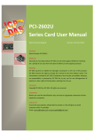
2.6.0 Introduction
MagicScan Process:
Step1. Set channel scan order and config.
Step2. Start MagicScan
Step3. Get MagicScan status
Step4. Get data
MagicScan Process Flow Diagram (PCI-1202) :
P1202_DriverInit(): Driver initial and get resource
P1202_ActiveBoard( ): Active board.
P1202_AddToScan( ): Set channel and config
and P1202_SaveScan( ), P1202_ClearScan( )
P1202_StartScan( ): Start MagicScan.
P1202_StartScanPostTrg( ), …PreTrg( ), …MiddleTrg( )
P1202_WaitMagicScanFinish(),
P1202_ReadScanStatus()
P1202_StopMagicScan( )
P1202_DriverClose() : Close driver and release resource
Version 2.05
Date: Jan-8, 2007
Page: 23
PCI-1202 Software Manual
2.6.1
P1202_ClearScan
This subroutine will initialize the MagicScan controller.
*This function will refer to the current active PCI-1202 board. Use the
P1202_ActiveBoard(….) to select the active board.
* Please refer to Note 1 in section 3.
Syntax :
WORD P1202_ClearScan();
Parameter :
Void
Return :
0 : No Error
Others : Please refer to section 1.2.
Demo :
DEMO11.C
Version 2.05
Date: Jan-8, 2007
Page: 24
PCI-1202 Software Manual
2.6.2
P1202_StartScan
This subroutine will start the MagicScan operation. This subroutine will return to
the caller before the MagicScan operation finish.
* The user can use P1202_WaitMagicScanFinish(..) or
P1202_ReadScanStatus(..) to check the status of MagicScan operation.
*This function will refer to the current active PCI-1202 board. Use the
P1202_ActiveBoard(..) to select the active board.
Syntax :
WORD P1202_StartScan(WORD wSampleRateDiv, WORD wNumCycles,
SHORT nPriority);
Parameters :
wSampleRateDiv :[Input] AD sampling rate = 8M / wSampleRateDiv
Ex: wSampleRateDiv = 80 sampling rate = 8M / 80 = 100K
wNumCycles :[Input] Number of MagicScan cycle to perform
nPriority :[Input] Set Thread’s Priority. Please refer to section 1.4
Return :
0 : No Error
Others : Please refer to section 1.2
Demo :
DEMO11.C
Version 2.05
Date: Jan-8, 2007
Page: 25
PCI-1202 Software Manual
2.6.3
P1202_StartScanPostTrg
To get a number of AD data from one or multi-channel after the external trigger
arrives.
*The user can use P1202_ReadScanStatus() to check status and use
P1202_StopMagicScan() to force the MagicScan to terminate.
* Please refer to Note 1 in the section 3
Syntax :
WORD P1202_StartScanPostTrg(WORD wSampleRateDiv, WORD
wNumCycles, SHORT nPriority);
Parameters :
wSampleRateDiv :[Input] AD sampling rate = 8M / wSampleRateDiv
Ex: wSampleRateDiv = 80 sampling rate = 8M / 80 = 100K
wNumCycles :[Input] number of A/D data for each scan channel
Total data number = wNumCycles * number of scan channel
nPriority :[Input] Set thread’s priority。Please refer to section 1.4
Return :
0 : No Error
Others : Please refer to section 1.2.
Demo :
DEMO23.C
Version 2.05
Date: Jan-8, 2007
Page: 26
PCI-1202 Software Manual
2.6.4
P1202_StartScanPreTrg
The Magic Controller keeps getting data after this function called. When the
external trigger arrives, the Magic Controller will stop getting data and return the
last wNumCycles data.
*The user can use P1202_ReadScanStatus() to check status and use
P1202_StopMagicScan() to force MagicScan to terminate.
Syntax :
WORD P1202_StartScanPreTrg(WORD wSampleRateDiv, WORD
wNumCycles, SHORT nPriority);
Parameters :
wSampleRateDiv :[Input] AD sampling rate = 8M / wSampleRateDiv
wSampleRateDiv = 80 sampling rate = 8M / 80 = 100K
wNumCycles :[Input] number of A/D data for each scan channel
Total data number = wNumCycles * number of scan channel
nPriority :[Input] Set thread’s priority。Please refer to section 1.4
Return :
0 : No Error
Others : Please refer to section 1.2
Demo :
DEMO24.C
Version 2.05
Date: Jan-8, 2007
Page: 27
PCI-1202 Software Manual
2.6.5
P1202_StartScanMiddleTrg
The Magic Controller keeps getting data. When the external trigger arrives, the
Magic Controller still gets N2 data and return the last (wNum-N2) data that
before external trigger and N2 data that after the trigger. So, the total AD data
returned is wNum data per channel.
*The user can use P1202_ReadScanStatus() to check status and use
P1202_StopMagicScan() to force MagicScan to terminate.
Syntax :
WORD P1202_StartScanMiddleTrg(WORD wSampleRateDiv, WORD wNum,
WORD wN2 , SHORT nPriority);
Parameters :
wSampleRateDiv :[Input] AD sampling rate = 8M / wSampleRateDiv
wSampleRateDiv = 80sampling rate = 8M / 80 = 100K
wNum :[Input] Total data per channel
wN2 :[Input] Number of data after external trigger arrives(per channel)
nPriority :[Input] Set Thread’s Priority。Please refer to section 1.4
Return :
0 : No Error
Others : Please refer to section 1.2.
Demo :
DEMO25.C
Version 2.05
Date: Jan-8, 2007
Page: 28
PCI-1202 Software Manual
2.6.6
P1202_ReadScanStatus
This subroutine will read the status of the MagicScan, Pre-trigger, Post-trigger
and Mid-trigger operation. The status should be checked continually to make
sure the scan is complete. If getting a status “0x80”, the scan is complete and
the data in buffer are ready.
*This function will refer to the current active PCI-1202 board. Use the
P1202_ActiveBoard(….) to select the active board.
Syntax :
Void P1202_ReadScanStatus(WORD *wStatus, DWORD *dwLowAlarm,
DWORD *dwHighAlarm);
Parameters :
*wStatus :[Output] address of wStatus which store status
Table 2.8.6.1 wStatus Value Table
wStatus Value(HEX)
Status
Description
0x00
initial
MagicScan Initial Status (Idle)
0x01
start
MagicScan Running
0x02
time out1
MagicScan stage 1 controller TimeOut
0x04
time out2
MagicScan stage 2 controller TimeOut
0x08
overflow
MagicScan FIFO overflow※
0x80
OK
MagicScan Complete
※ Please refer to Note 2 in section 3
*dwLowAlarm :[Output] address of wLowAlarm which store the MagicScan
alarm status
*dwHighAlarm :[Output] address of wHighAlarm which store the MagicScan
alarm status
dwLowAlarm(bit 0~15)
Bit
F
E
D
C
B
A
9
8
7
6
5
4
3
2
1
0
channel
15
14
13
12
11
10
9
8
7
6
5
4
3
2
1
0
1F 1E 1D 1C 1B 1A
19
18
17
16
15
14
13
12
11
10
31
25
24
23
22
21
20
19
18
17
16
dwLowAlarm(bit 16~31)
Bit
channel
30
29
28
27
26
dwLowAlarm 32 bits corresponding to 32 channels
Version 2.05
Date: Jan-8, 2007
Page: 29
PCI-1202 Software Manual
Ch ? = 0 no low alarm
Ch ? = 1 low alarm on
Example:
dwLowAlarm=0
dwLowAlarm=1
dwLowAlarm=3
all channels OK, no low alarm
channel_0 is low alarm, others are OK
channel_0 and channel_1 are low alarm, others are OK
dwHighAlarm(bit 0~15)
Bit
F
E
D
C
B
A
9
8
7
6
5
4
3
2
1
0
channel
15
14
13
12
11
10
9
8
7
6
5
4
3
2
1
0
1F 1E 1D 1C 1B 1A
19
18
17
16
15
14
13
12
11
10
31
25
24
23
22
21
20
19
18
17
16
dwHighAlarm(bit 16~31)
Bit
channel
30
29
28
27
26
dwHighAlarm32 bits corresponding to 32 channels
Ch ? = 0 no high alarm
Ch ? = 1 high alarm on
Example:
dwHighAlarm=0 all channels OK, no high alarm
dwHighAlarm=4 high alarm of channel_2 is on, others are OK
dwHighAlarm=7 high alarm of channel_0,1,2 are on, others are OK
Return :
Void
Demo :
DEMO11.C
Version 2.05
Date: Jan-8, 2007
Page: 30
PCI-1202 Software Manual
2.6.7
P1202_AddToScan
This subroutine will add one channel into the MagicScan circular queue. The
maximum channels could be added into MagicScan circular queue is 48. The
scan sequence is the order of adding channel into scan queue.
Example:
P1202_AddToScan(1, 0, 1, 0, 0, 0);
P1202_AddToScan(1, 0, 1, 0, 0, 0);
P1202_AddToScan(0, 0, 1, 0, 0, 0);
Scan order is ch1 -> ch1 -> ch0 -> ch1 -> ch1 -> ch0 -> ch1-> …
*This function will refer to the current active PCI-1202 board. Use the
P1202_ActiveBoard(….) to select the active board.
Syntax :
WORD P1202_AddToScan(WORD wAdChannel, WORD wConfig, WORD wAverage,
WORD wLowAlarm, WORD wHighAlarm, WORD wAlarmType);
Patermeters :
wAdChannel :[Input] AD channel number
wConfig :[Input] the configuration code. Refer to "Section 1.3 Configuration
Table"
wAverage :[Input] the factor of digital average filter. Average wAverage data to
one and the smallest value is 1
The factor of digital average filter :
When the wAverage is 5, it will average 5 data to 1. The sampling rate will
become one fifth.
wLowAlarm :[Input] 12 bits low alarm data
wHighAlarm :[Input] 12 bits high alarm data
wAlarmType :[Input] Alarm type
Version 2.05
Date: Jan-8, 2007
Page: 31
PCI-1202 Software Manual
Table 2.8.7.1 Alarm Type Define Table
AlarmType Value
Alarm Type
Comment
0
No alarm
Close
1
High alarm
Buff[?] > High alarm
2
Low alarm
Buff[?] < Low alarm
3
In alarm
Low < Buff[?] < High
4
Out alarm
Out range
Example:
P1202_AddToScan(0, 0, 1, 0, 0, 0)
wAdChannel =0 Add channel 0 to scan.
wConfig = 0Set AD range is 5V~ -5V
wAverage=1No Average
wLowAlarm=0 No LowAlarm
wHighAlarm=0 No HighAlarm
wAlarmType=0Close Alarm
Return :
0 : No Error
Others : Please refer to section 1.2
Demo : DEMO11.C
Version 2.05
Date: Jan-8, 2007
Page: 32
PCI-1202 Software Manual
2.6.8
P1202_SaveScan
This subroutine specifies the starting address of AD data buffer for MagicScan,
it should be set before MagicScan start.
Syntax :
Void P1202_SaveScan(WORD wAdChannel, WORD wBuf[]);
Parameters :
wAdChannel :[Input] Scan number in the scan queue.
(Note: not the A/D channel number.)
Example :
The first scan channel may be any channel. But the wAdChannel must be 0 in
this subroutine, because the wAdChannel number is according to the scanning
order.
wBuf :[Output] Starting address of AD data buffer for channel specified in
wAdChannel
Example:
WORD wV0[100000];
WORD wV2[100000];
// AD ch:0 buffer
// AD ch:2 buffer
wRetVal=P1202_ClearScan();
//**** For PCI-1202
wRetVal += P1202_AddToScan(0,0,1,0,0,0);
// add CH:0 to scan
wRetVal += P1202_SaveScan(0,wV0);
//CH0 is the first join channel for scan, so the scanning order is 0.
//Save the data of scanning channel that order is 0 to wV0[].
wRetVal += P1202_AddToScan(4,0,1,0,0,0);
// Join CH4 to the scan queue
wRetVal += P1202_SaveScan(1,wV2);
//Note:The “1” means the scanning order is second, not physical channel.
// CH4 is the second channel added into scan queue, so the scanning order is 1.
// Save the data of scanning channel that order is 1 to wV2[].
wSampleRateDiv=80;
//
Sampling rate = 8M / 80 = 100k
P1202_StartScan(wSampleRateDiv,DATALENGTH,nPriority); // Start scan
Return :
0 : No Error
Others : Please refer to section 1.2
Demo :.DEMO11.C
Version 2.05
Date: Jan-8, 2007
Page: 33
PCI-1202 Software Manual
2.6.9
P1202_WaitMagicScanFinish
This subroutine will wait until the MagicScan operation is finished.
*This function will refer to the current active PCI-1202 board. Use the
P1202_ActiveBoard(….) to select the active board.
Syntax :
Void P1202_WaitMagicScanFinish(WORD *wStatus, DWORD *dwLowAlarm,
DWORD *dwHighAlarm);
Parameters :
wStatus :[Output] address of wStatus which store the MagicScan status
Table 2.8.6.1 wStatus Status Table
wStatus Value(HEX)
Status
Describe
0x00
initial
MagicScan Initial Status(Idle)
0x01
start
MagicScan Running
0x02
time out1
MagicScan stage 1 controller TimeOur
0x04
time out2
MagicScan stage 2 controller TimeOut
0x08
overflow
MagicScan FIFO overflow※PS
0x80
OK
MagicScan Complete
*Note:Please refer to Note 2 in Section 3
*dwLowAlarm :[Output] address of wLowAlarm which store the MagicScan
alarm status
*dwHighAlarm :[Output] address of wHighAlarm which store the MagicScan
alarm status
dwLowAlarm(bit 0~15)
Bit
F
E
D
C
B
A
9
8
7
6
5
4
3
2
1
0
channel
15
14
13
12
11
10
9
8
7
6
5
4
3
2
1
0
1F 1E 1D 1C 1B 1A
19
18
17
16
15
14
13
12
11
10
31
25
24
23
22
21
20
19
18
17
16
dwLowAlarm(bit 16~31)
Bit
channel
30
29
28
27
26
wLowAlarm 32 bits corresponding to 32 channels
Version 2.05
Date: Jan-8, 2007
Page: 34
PCI-1202 Software Manual
Ch ? = 0 No low alarm
Ch ? = 1 Low alarm on
Example:
dwLowAlarm=0
dwLowAlarm=1
dwLowAlarm=3
all channels OK, no low alarm
low alarm of channel_0 is on, others are OK
low alarm of channel_0 and channel_1 are on,
others are OK
dwHighAlarm(bit 0~15)
Bit
F
E
D
C
B
A
9
8
7
6
5
4
3
2
1
0
channel
15
14
13
12
11
10
9
8
7
6
5
4
3
2
1
0
1F 1E 1D 1C 1B 1A
19
18
17
16
15
14
13
12
11
10
31
25
24
23
22
21
20
19
18
17
16
dwHighAlarm(bit 16~31)
Bit
channel
30
29
28
27
26
dwHighAlarm 32 bits corresponding to 32 channels
Ch ? = 0 No high alarm occurs
Ch ? = 1 High alarm on
Example:
dwHighAlarm=0 all channels OK, no high alarm
dwHighAlarm=4 high alarm of channel_2 is on, others are OK
dwHighAlarm=7 high alarm of channel_0,1,2 are on, others are OK
Return :
Void
Demo :
DEMO11.C
Version 2.05
Date: Jan-8, 2007
Page: 35
PCI-1202 Software Manual
2.6.10
P1202_StopMagicScan
Stop MagicScan.
Syntax :
Void P1202_StopMagicScan(Void);
Parameter :
Void
Return :
Void
Demo :
DEMO14.C
Version 2.05
Date: Jan-8, 2007
Page: 36
PCI-1202 Software Manual
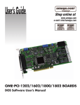
2.7 The M_Functions
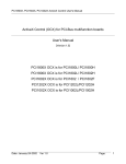
2.7.0 Introduction
M_Function Process Flow Chart:
:
M Functions
D/A
Device
FIFO
MagicScan
Controller
A/D
*MagicScan Control:Please refer to Note 1 in the Section 3
Table 2.9.0.1 M_Function Feature Table
Function
Name
D/A
M_FUN_1
Analog Output 0
Output sine wave
Analog Input 0
+10V ~ -10V
M_FUN_2
Analog Output 0
Output arbitrary wave form
Analog Input 0
+10V ~ -10V
M_FUN_3
Analog Output 0
Output sine wave
channel/gain programmable
(32 channels max.)
M_FUN_4
Analog Output 0
Output square wave, semisquare-wave or sine wave
channel/gain programmable
(32 channels max.)
Date: Jan-8, 2007
Page: 37
Version 2.05
A/D
PCI-1202 Software Manual
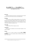
2.7.1
P1202_M_FUN_1
This subroutine output sine wave from DA channel 0 according to the parameter
wDaNumber and fDaAmplitude. By the wDaWave, the number of DA waveform
to be output is programmable. It can output sine wave from DA channel 0
and get data from AD Channel 0 at the same time. Users also need to set
sampling rate and data number of AD.
*Please refer to 「 PCI-1202/1602/1800/1802 Hardware manual 」 for more
information.
Syntax :
WORD P1202_M_FUN_1(WORD wDaNumber, WORD wDaWave, float
fDaAmplitude, WORD wAdSampleRateDiv, WORD wAdNumber, WORD
wAdConfig, float fAdBuf[], float fLowAlarm, float fHighAlarm)
Parameters :
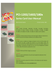
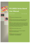
wDaNumber: [Input] The element number of one sine wave. When the number
increased, the wave will be more smoothly, but the speed of output a sine wave
will be decreased.
Example1:
This picture set wDaNumber
5, it will output a sine wave that
make up by 5 of automatically
generated DA value. And, the
output speed depends upon
computer performance.
wDaWave : [Input] Number of DA waveform to be output
Example2:
When wDaWave is 2, it will
output the sine wave defined by
wDANumber twice.
Version 2.05
Date: Jan-8, 2007
Page: 38
PCI-1202 Software Manual
fDaAmplitude : [Input] Amplitude of DA output
*fDaAmplitude range is -10~10
NOTE : the hardware J1 must be set on +/-10V
wAdSampleRateDiv:
[Input] AD sampling rate = 8000000 / wAdSampleRateDiv samples/sec
wAdNumber: [Input] Number of AD data to be read
wAdConfig : [Input] A/D input range configuration code
Please refer to section 1.3
fAdBuf[] : [Output] the starting address of fAdBuf which store the A/D data
fLowAlarm : [Input] low alarm limit. if fAdBuf[?]< fLowAlarm
LowAlarm on
fHighAlarm : [Input] high alarm limit. if fAdBuf[?]>fHighAlarm
HighAlarm on
Return :
0 : No Error
Others : Please refer to section 1.2
Demo : DEMO5.C
Version 2.05
Date: Jan-8, 2007
Page: 39
PCI-1202 Software Manual
2.7.2
P1202_M_FUN_2
The P1202_M_FUN_2 usage like P1202_M_FUN_1, but it will not compute the
waveform image automatically. Users must set each DA value of the output
wave form.
It can output the user defined waveform from DA channel 0 and get data
from AD Channel 0 at the same time.
*Please refer to「PCI-1202/1602/1800/1802 Hardware manual」for more
information.
Syntax :
WORD P1202_M_FUN_2(WORD wDaNumber, WORD wDaWave, WORD
wDaBuf[], WORD wAdSampleRateDiv, WORD wAdNumber, WORD wAdConfig,
WORD wAdBuf[]);
Parameters :
wDaNumber: [Input] number of D/A samples in one waveform
Please refer to Example 1 in the P1202_M_FUN_1
wDaWave : [Input] Number of DA waveform to be output
Please refer to Example 2 in the P1202_M_FUN_1
wDaBuf[] : [Output] The array stores the D/A waveform image
wAdSampleRateDiv:
[Input] AD sampling rate = 8000000 / wAdSampleRateDiv samples/sec
wAdNumber: [Input] Number of AD data to be read
wAdConfig : [Input] A/D input range configuration code
Please refer to section 1.3
wAdBuf[] : [Output] the starting address of fAdBuf which store the A/D data
Return :
0 : No Error
Others : Please refer to section 1.2
Demo :
DEMO7.C
Version 2.05
Date: Jan-8, 2007
Page: 40
PCI-1202 Software Manual
2.7.3
P1202_M_FUN_3
This subroutine output sine wave from DA channel 0 according to the
parameters wDaNumber and fDaAmplitude. By the wDaWave, the number of
DA waveform output is programmable.
It can output sine wave from DA channel 0 and get data from channel
scan at the same time. wAdNumber and wAdSampleRateDiv are used to set
AD data number and sampling rate.
*Please refer to 「 PCI-1202/1602/1800/1802 Hardware manual 」 for more
information.
Syntax :
WORD P1202_M_FUN_3(WORD wDaNumber, WORD wDaWave, float
fDaAmplitude, WORD wAdSampleRateDiv, WORD wAdNumber, WORD
wChannelStatus[], WORD wAdConfig[], float fAdBuf[], float fLowAlarm, float
fHighAlarm)
Parameters :
wDaNumber: [Input] The element number of one sine wave. When the number
increased, the wave will be more smoothly, but the speed of output a sine wave
will be decreased
Please refer to Example 1 in the P1202_M_FUN_1
wDaWave : [Input] Number of DA waveform to be output
Please refer to Example 2 in the P1202_M_FUN_1
fDaAmplitude : [Input] Amplitude of DA output
fDaAmplitude value range = -10~10
NOTE : the hardware J1 must be set on +/-10V
wAdSampleRateDiv:
[Input] AD sampling rate = 8000000 / wAdSampleRateDiv samples/sec
Version 2.05
Date: Jan-8, 2007
Page: 41
PCI-1202 Software Manual
wAdNumber: [Input] Number of AD data to be read
wAdChannel[]:[Input] 1 = scan channel(index) enable,
0 = scan channel (index) disable
Example3:
wAdChannel[0] = 1 Set “scan channel 0” enable
wAdChannel[0]=0 Set “scan channel 0” disable
wAdChannel[2]=1 Set “scan channel 2” enable
wAdConfig[]:[Input]A/D input range configuration code
Please refer to section 1.3
fAdBuf[] : [Output] the starting address of fAdBuf which store the A/D data
fLowAlarm : [Input] low alarm limit. if fAdBuf[?]< fLowAlarm
LowAlarm on
fHighAlarm : [Input] high alarm limit. if fAdBuf[?]>fHighAlarm
HighAlarm on
Return :
0 : No Error
Others : Please refer to section 1.2.
Demo :
DEMO9.C
Version 2.05
Date: Jan-8, 2007
Page: 42
PCI-1202 Software Manual
2.8 The Single Board Batch Capture
2.8.0
Introduction
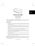
FunB Batch Capture Procedures
P1202_DriverInit():Driver initial and get resource
P1202_ActiveBoard( ): Active board.
P1202_FunB_Start():Start Scan.
P1202_FunB_ReadStatus(): Get state
P1202_FunB_Get(): Get data
P1202_FunB_Stop(): Stop scan
P1202_DriverClose() : Close drive and release source
Architecture
Thread
Ch0Val0 Ch1Val0 Ch2Val0 Ch0Val1 Ch1Val1 Ch2Val1
(User’s Buffer: xx MB)
FIFO
MagicScan
Controller
Version 2.05
P1202_FunB_ReadStatus( )
Date: Jan-8, 2007
Page: 43
PCI-1202 Software Manual
2.8.1 P1202_FunB_Start
This subroutine starts the batch capture and stores data into a
specified memory. This function works on only one PCI-1202
board system.
*Please refer to section 2.9.0 for more information.
Syntax :
WORD P1202_FunB_Start (WORD wClockDiv0, WORD wChannel0[],
WORD wConfig0[], WORD *Buffer0, DWORD dwMaxCount0,
SHORT nPriority);
Parameters :
wClockDiv0:[Input] The AD sampling rate devisor .
The sampling rate is 8M / wClockDiv0
wChannel0[]:[Input] 0 = disable scan channel (index),
1 = enable scan channel (index)
Example1:
wChannel0[0] = 1 set “scan channel 0” enable
wChannel0[0]=0 set “scan channel 0” disable
wChannel0[2]=1 set “scan channel 2” enable
wConfig0[]:[Input] Configuration code for each channel.
Refer to "Section 3.1 Configuration Table"
*Buffer0: [Output] Buffer to store the A/D data
dwMaxCount0: [Input] the data length to get in each getting data process.
If the getting data thread gets “dwMaxCount0”
data, the status that P1202_FunB_ReadStatus
returned is 0, at this time users can copy data from
Buffer0, then start the next getting process
nPriority :[Input] To set the thread’s priority.*Please refer to section 1.4
Return :
0 : No Error
Others : Please refer to section 1.2
Demo :
DEMO21.C
Version 2.05
Date: Jan-8, 2007
Page: 44
PCI-1202 Software Manual
2.8.2
P1202_FunB_ReadStatus
This function returns the status of Fun_B batch capture.
If the getting data thread gets “dwMaxCount0” data, the status is 0,
at this time users can copy data from Buffer0 to another memory, then
start the next getting process.
Syntax :
WORD P1202_FunB_ReadStatus( Void );
Parameter :
Void
Return :
0: data is ready
1: data not ready
Demo :
DEMO21.C
Version 2.05
Date: Jan-8, 2007
Page: 45
PCI-1202 Software Manual
2.8.3
P1202_FunB_Stop
This subroutine will stop the batch capture function.
Syntax :
WORD P1202_FunB_Stop(Void);
Parameter :
Void
Return :
0 : No Error
Others : Please refer to section 1.2
Demo : DEMO21.C
2.8.4 P1202_FunB_Get
This function will retrieve the number of A/D samples that have been acquired.
Syntax:
WORD P1202_FunB_Get(DWORD *P0);
Parameter :
*P0: [Output] how many A/D data has been acquired
Return :
0 : No Error
Others : Please refer section 1.2
Demo : DEMO21.C
Version 2.05
Date: Jan-8, 2007
Page: 46
PCI-1202 Software Manual
2.9 Multi-board Batch Capture
(two boards operating simultaneously)
2.9.0
P1202_FunA_Start
When there are two boards installed on a PC, using this subroutine to start the
batch capture from the two boards simultaneously and store data into memory.
*Please refer to section 2.9.0 for more information.
Syntax :
WORD P1202_FunA_Start(WORD wClockDiv0, WORD wChannel0[],
WORD wConfig0[], WORD *Buffer0, DWORD dwMaxCount0,
WORD wClockDiv1, WORD wChannel1[],
WORD wConfig1[], WORD *Buffer1, DWORD dwMaxCount1
Short nPriority);
Parameters :
WClockDiv0: [Input] AD sampling rate devisor for the first board.
The sampling rate is 8M / wClockDiv0
WChannel0[]:[Input] (0=no scan, 1=scan) For each channel of the first board
Example1:
wChannel0[0] = 1 Scan Channel 0 for the first board
wChannel0[0] = 0 No scan Channel 0 for the first board
wChannel0[2] = 1 Scan Channel 2 for the first board
WConfig0[]:[Input] configuration code for each channel of the first board
Please refer to section 1.3
*Buffer0: [Output] Buffer to store the A/D data of the first board
dwMaxCount0:[Input] To specify the data length of the first board
wClockDiv1: [Input] The AD sampling rate devisor for the 2nd board
The sampling rate is 8M / wClockDiv1
WChannel1[]:[Input] (0=no scan, 1=scan) For each channel of the 2nd board
Example1:
wChannel1[0] = 1 Scan Channel 0 for the 2nd board
wChannel1[0] = 0 No scan Channel 0 for the 2nd board
wChannel1[2] = 1 Scan Channel 2 for the 2nd board
WConfig1[]:Configuration code for each channel of the 2nd board
Please refer to section 1.3
Version 2.05
Date: Jan-8, 2007
Page: 47
PCI-1202 Software Manual
*Buffer1: [Output] Buffer to store the A/D data of the 2nd board
DwMaxCount1: [Input] To specify the data length of the 2nd board
nPriority:[Input]To set the thread’s priority. Please refer to section 1.4.
Return :
0 : No Error
Others : Please refer to section 1.2
Demo Program : DEMO20.C
2.9.1
P1202_FunA_ReadStatus
This subroutine will read the status of Fun_A batch capture.
Syntax :
WORD P1202_FunA_ReadStatus( Void );
Parameter :
Void
Return :
0: data is ready
1: data not ready
Demo : DEMO20.C
2.9.2
P1202_FunA_Stop
This subroutine will stop the batch capture function.
Syntax:
WORD P1202_FunA_Stop(Void);
Parameter :
Void
Return :
Void
Demo :
DEMO20.C
Version 2.05
Date: Jan-8, 2007
Page: 48
PCI-1202 Software Manual
2.9.3
P1202_FunA_Get
This function will retrieve the number A/D samples acquired.
Syntax:
WORD P1202_FunA_Get(DWORD *P0, DWORD *P1);
Parameters :
*P0:[Output] how many A/D data has been acquired for the first board
*P1:[Output] how many A/D data has been acquired for the 2nd board
Return :
0 : No Error
Others : Please refer to section 1.2
Demo : DEMO20.C
Version 2.05
Date: Jan-8, 2007
Page: 49
PCI-1202 Software Manual
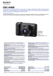
2.10 The Continuous Capture
2.10.0
Introduction
Continuous Capture Flow Diagram (PCI-1202) :
P1202_DriverInit():Driver initial and get resource
P1202_ActiveBoard( ): Active board.
P1202_Card0_StartScan():Start MagicScan
P1202_Card1_StartScan().
P1202_Card0_ReadStatus(): Get state and data
P1202_Card1_ReadStatus()
P1202_Card0_Stop(), P1202_Card1_Stop()
P1202_DriverClose() : Close drive and release source
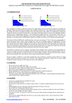
Architecture
Internal Buffer (Queue,135KS)
Thread
FIFO
MagicScan
Controller
Version 2.05
P1202_FunB_ReadStatus( )
Ch0Val0 Ch1Val0 Ch2Val0 Ch0Val1 Ch1Val1 Ch2Val1
Ch0Val0 Ch0Val1 Ch1Val0 Ch1Val1 Ch2Val0 Ch2Val1
(User’s Buffer:wBuf[],wBuf2[])
Date: Jan-8, 2007
Page: 50
PCI-1202 Software Manual
2.10.1 P1202_Card0_StartScan
This subroutine will start the channel scan and continuous capture function on
the first board. It is recommended to get ADs for long time and low sampling
rate. Otherwise, the chance of FIFO overflow could be increased. The sampling
rate under 40KHz is recommended.
*Please refer to 「 PCI-1202/1602/180x Hardware User Manual」for more
information.
Syntax :
WORD P1202_Card0_StartScan(WORD wSampleRateDiv, WORD
wChannelStatus[], WORD wChanelConfig[], WORD wCycles);
Parameters :
wSampleRateDiv : [Input] AD sampling rate = 8M / wSampleRatediv.
Ex: wSampleRateDiv = 800, sampling rate = 8M / 800 =10K
wChannelStatus[] : [Input] (0=no scan, 1=scan) for each channel
Example1:
wChannelStatus [0] = 1 Scan Channel 0
wChannelStatus [0] = 0 No scan Channel 0
wChannelStatus [2] = 1 Scan Channel 2
wChannelConfig[] : [Input] configuration code for each channel
Example : wChannelConfig[1]=0, set the configuration of channel1 is 0
wCycles : [Input] number of A/D data for each scan channel
Total data number=wCycles * number of scan channel
Return :
0 : No Error
Others : Please refer to section 1.2
Demo : DEMO13.C
Version 2.05
Date: Jan-8, 2007
Page: 51
PCI-1202 Software Manual
2.10.2
P1202_Card0_ReadStatus
This subroutine will read the status of the Continuous Capture on first board. It
only checks the status of capture process without stops operation. When the
data ready, the return value will be 0. Users can continue capturing data in a
loop until stop the capturing process.
*This function will refer to the current active PCI-1202 board. Use the
P1202_ActiveBoard(….) to select the active board.
Syntax :
P1202_Card0_ReadStatus(WORD wBuf[], WORD wBuf2[], DWORD *dwP1,
DWORD *dwP2, WORD *wStatus);
Parameters :
wBuf[]:[Output] store data by scan order(012…N012…N……012…N)
The data sequence in the wBuf[] is as follows :
Ch0Val0
Ch1Val0
Ch2Val0
Ch0Val1
Ch1Val1
Ch2Val1
wBuf2[] :[Output] in channel sequence
order(00000…..11111……22222….NNNNN….)
The data sequence in the wBuf2[] is as follows :
Ch0Val0
Ch0Val1
Ch1Val0
Ch1Val1
Ch2Val0
Ch2Val1
*dwP1 :[Input/Output] reserved
*dwP2 :[Input/Output] reserved
*wStatus :[Output] 1=thread start, 2=TimeOut, 8=FIFO overflow,
0x80=thread finish, 5=buffer full
Return :
0 : Ready
1 : No data
2 : FIFO overflow
3 : Thread time-out
4 : Buffer Full
Demo : DEMO13.C
Version 2.05
Date: Jan-8, 2007
Page: 52
PCI-1202 Software Manual
2.10.3
P1202_Card0_Stop
This subroutine will stop the continuous capture function on first board.
Syntax :
Void P1202_Card0_Stop(Void);
Parameter :
Void
Return :
0 : No Error
Others : Please refer to section 1.2.
Demo : DEMO13.C
Version 2.05
Date: Jan-8, 2007
Page: 53
PCI-1202 Software Manual
2.10.4
P1202_Card1_StartScan
This subroutine will start the channel scan and continuous capture function on
the second board. It is recommended using for long time and low sampling rate
ADs. Otherwise, the chance of FIFO overflow could be increased. The sampling
rate less than 40KHz is recommended.
*Please refer to 「 PCI-1202/1602/180x Hardware User Manual 」 for more
information.
Syntax :
WORD P1202_Card1_StartScan(WORD wSampleRateDiv, WORD
wChannelStatus[], WORD wChanelConfig[], WORD wCount);
Parameters :
wSampleRateDiv :[Input] AD sampling rate = 8M / wSampleRateDiv.
Ex: wSampleRate = 800 sampling rate = 8M / 800 = 10K
wChannelStatus[] :[Input] (0=no scan, 1=scan) for each channel
Example1:
wChannelStatus[0] = 1 Scan Channel 0
wChannelStatus[0] = 0 No scan Channel 0
wChannelStatus[2] = 1 Scan Channel 2
wChannelConfig[] :[Input] configuration code for each channel
Ex: wChannelConfig[1] = 0 Set 0 as the configuration of channel1
wCycles:[Input] number of A/D data for each scan channel
Total data number=wCycles * number of scan channel
Return :
0 : No Error
Others : Please refer to section 1.2.
Demo : DEMO14.C
Version 2.05
Date: Jan-8, 2007
Page: 54
PCI-1202 Software Manual
2.10.5
P1202_Card1_ReadStatus
This subroutine will read the status of the Continuous Capture on the second
board. It only checks the status of continuous capture without stops the
operation. When the data ready, the return value will be 0. Users can continue
capturing data in a loop until stop the capturing process.
*This function will refer to the current active PCI-1202 board. Use the
P1202_ActiveBoard(….) to select the active board.
Syntax :
P1202_Card1_ReadStatus(WORD wBuf[], WORD wBuf2[], DWORD *dwP1,
DWORD *dwP2, WORD *wStatus);
Parameters :
wBuf[] :[Output] store data by scan order (012…N012…N……012…N)
The data sequence in the wBuf[] is as follows :
Ch0Val0
Ch1Val0
Ch2Val0
Ch0Val1
Ch1Val1
Ch2Val1
wBuf2[] :[Output] store data by channel sequence
(00000…..11111……22222….NNNNN.)
The data sequence in the wBuf2[] is as follows :
Ch0Val0
Ch0Val1
Ch1Val0
Ch1Val1
Ch2Val0
Ch2Val1
*dwP1 :[Input/Output] reserved
*dwP2 :[Input/Output] reserved
*wStatus :[Output] 1 = thread start, 2 = TimeOut, 8 = FIFO overflow,
0x80 = thread finish, 5 = buffer full
Return :
0 : Ready
1 : No data
2 : FIFO overflow
3 : Thread time-out
4 : Buffer Full
Demo : DEMO14.C
Version 2.05
Date: Jan-8, 2007
Page: 55
PCI-1202 Software Manual
2.10.6
P1202_Card1_Stop
This subroutine will stop the continuous capture function of the 2nd board.
Syntax :
Void P1202_Card1_Stop(Void);
Parameter :
Void
Return :
Void
Demo :
DEMO14.C
Version 2.05
Date: Jan-8, 2007
Page: 56
PCI-1202 Software Manual
2.11
The Other Functions
2.11.0
P1202_DelayUs
This is a machine independent timer. This function is used to delay a settling
time or used as a general purposed machine independent timer.
*This function will refer to the current active PCI-1202 board. Use the
P1202_ActiveBoard(….) to select the active board.
Syntax :
WORD P1202_DelayUs(WORD wDelayUs);
Parameter :
wDelayUs : number of us to delay, 8191 Max
wDelayUs=1
delay 1 us
wDelayUs=1000 delay 1000 us = 1 ms
wDelayUs=8191 delay 8191 us = 8.191 ms (maximum delay)
wDelayUs=8192 invalidate delay (will return error)
Return :
0 : No Error
Others : Please refer to section 1.2
Demo : DEMO1.C
Long Time Delay :
WORD DelayMs(WORD wDelayMs) // maximum delay=4294967.295 sec
{
WORD wDelay,wRetVal
wRetVal=0;
for (wDelay=0; wDelay<wDelayMs; wDelay++)
wRetVal+=P1202_DelayUs(1000);
return (wRetVal);
}
Version 2.05
Date: Jan-8, 2007
Page: 57
PCI-1202 Software Manual
3. Appendix
※ Note1:
[MagicScan controller]
This is a mechanism of hardware channel scan. The scan channel sequence
and config need be preset. When the scan start, the MagicScan Controller
will switch channel and config according to the channel sequence
automatically and get data into FIFO. At the same time, the driver will
translate data in FIFO to the Buffer.
The only thing that user need to do is using function to get data from
Buffer. The advantage of this mechanism is improving channel scan
performance effectively.
※ Note2:
[FIFO Overflow]
When the FIFO full, the last data will cover the first data, it causes data lose
and called “FIFO Overflow”.
To prevent FIFO Overflow, it is recommended to suspend another
program like IE, anti-virus or select other card that have bigger FIFO like 8K
series card.
Version 2.05
Date: Jan-8, 2007
Page: 58
PCI-1202 Software Manual
4. DEMO
There are more than 20 demo programs provided as the following list:
demo1: one board, D/I/O test, D/A test, A/D polling & pacer trigger test, general test
demo2: two board, same as demo1
demo3: one board, all 32 channels of A/D by software trigger(by polling)
demo4: two board, same as demo3
demo5: one board, M_function_1 demo
demo6: two board, same as demo5
demo7: one board, M_function_2 demo
demo8: two board, same as demo7
demo9: one board, M_function_3 demo
demo10: two board, same as demo9
demo11: one board, MagicScan demo
demo12: two board, same as demo11
demo13: one board, continuous capture demo
demo14: two board, continuous capture demo (Windows 95/NT only)
demo15: all installed board, D/I/O test for board number identification
demo16: one board, performance evaluation demo
demo17: one board, MagicScan demo, scan sequence: 435
demo18: one board, MagicScan demo, scan 32 channel, show channel
0/1/15/16/17
demo19: one board, A/D calibration.
demo20: two board, P1202_FUNA, continuous capture demo
demo21: single board, P1202_FUNB, continuous capture demo
demo23: single board, post-trigger demo
demo24: single board, pre-trigger demo
demo25: single board, middle-trigger demo
Refer to the company floppy disk for details.
Version 2.05
Date: Jan-8, 2007
Page: 59