1
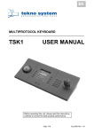
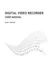
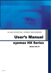
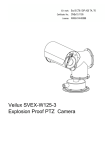
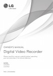
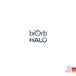
PREFACE 1. Please read this manual carefully before installation and keep it in hand for your reference. 2. Please abide by all the cautions on the equipment and manual, the operation should be made strictly on the direction of manual. 3. Do not place this unit on an unstable desk, tripod, bracket and mount. Avoiding potential damage; 4. Please cut off the power before cleaning, do not use any liquid cleaners or aerosol cleaners; Do not make any liquid spilled or an object fallen into dome camera. 5. In order to avoid the accident, please do not install the unit on the unstable mount, wall or ceiling. 6. Please comply with all security standard of electric when connecting cables together. Please use the included power. The technology of anti-surge was applied into the RS-485 adaptor and video signal to prevent the dome camera from damage caused by 500W thunder shock, surge and pulse signal. The sufficient distance should be made between RS-485 or video signal and high voltage equipment or cable on transmission. If needed, please establish enough protection measures against thunder or surf. 7. Do not attempt to repair this unit on yourself if equipment on problem. Please call the authorized service personnel. 8. No matter camera is working or not, never aim the camera at sun or illuminator object. Otherwise, the permanent damage may be caused to the camera’s CCD chip. 9. The equipment can’t suffer big shock or be placed on the vibration platform. 10. This equipment shouldn’t be exposed in a moist place or any place with caustic gas. 1 CONTENT Product Introduction---------------------------------------------------------------------------3 Specification -------------------------------------------------------------------------------------4 Connection & Setting---------------------------------------------------------------------------6 Protocol & Address code Setting ------------------------------------------------------------7 DIP switch Setting-------------------------------------------------------------------------------8 Speed dome control by keyboard------------------------------------------------------------10 Speed dome control by OSD------------------------------------------------------------------13 Accessory diagram------------------------------------------------------------------------------25 Necessary & optional accessory of indoor dome camera-------------------------------26 Necessary & optional accessory of outdoor dome camera-----------------------------26 Optional mount and accessory of indoor & outdoor dome----------------------------26 Address code and DIP switch reference diagram----------------------------------------27 2 Chapter 1: Characteristics Camera specification *The speed dome support different integrated camera module including SONY, LG, CNB, YOKO, HITACHI, SUMSUNG…… Powerful Pan/Tilt function: *Max. 400°/sec high speed Pan/Tilt turning *Adopted with vector driving technology, Pan/Tilt motions are accomplished in the shortest path. As a result, time to target is reduced dramatically and the video on the monitor is very natural to watch. The lowest speed can touch 0.05°/S. Preset, Pattern, Swing, Privacy mask, Group and more functions *Up to 128 pieces preset point can be memorized. The additional information such as dwell time, alarm action, label …... can be set as demand. *Up to 8 pieces point-to-point auto scan can be memorized. Support proportional shift between zoom and speed. *Up to 4 patterns can be recorded and played back. It can record 500 operation commands. *Up to 8 pieces GROUP can be stored, the function enables the camera to move repetitively with combination of Preset or Pattern or Swing. A group contained Max.20 presets, patterns or swings. *Max.8 of Privacy masks can be located wherever it is required to protect private life. (Only Sony camera module support this function) *Support Schedule function. PTZ lens control *Max. 1024 cameras can be controlled at the same time by RS-485 bus communication. *Pelco-D, Pelco- P, VC, Sony, EVI protocol can be selected. OSD Menu * The situation of camera can be displayed on screen with OSD menu function. The detailed camera function also can be set with OSD menu. *The information of camera series number, Pan/Tilt position, alarm in/out, preset all can be shown on screen or not with OSD menu setup; Convenient installation and operation *With built-in fan & heater and the weather-proof design, the product is very suitable for application in outdoor environment. 3 *The structure of dome camera meets the demand of IP66 standard. *The design concept of high-speed dome and mounting based on convenient installation. CHAPTER 2: Specifications 2.1 Configuration of Speed Dome Camera Product Photo Speed Dome Dimension Products Diagram 4 2.2 Specifications of High Speed Dome Camera Camera Camera Type & Specifications Sensor 1/4" IT Exview HAD CCD SONY Resolution 520 lines S/N >48db Zoom Ratio 30 times optical zoom; 10 times digital zoom Focal Length F1.6; f=3.3-99mm Min. Illumination 0.1Lux Image Freeze Yes Day/Night Yes Focus Auto/Manual Iris Auto White Balance Auto BLC ON/OFF selectable by OSD menu. Pan/Tilt Turning Scope Pan 360°; Tilt 90° Preset 360°/Sec Manual 0.025°~120°/Sec Swing Speed 200°/Sec Auto Scan 15°/Sec~60°/Sec Preset Quantity 128 Pattern 2 Patterns, 200 commands every one Swing 8 Group 5 Groups and each with 10 actions Protocol Pelco-D; Pelco-P; VC; WORLD Support camera module setup and speed pan/tilt setup OSD Programmable OSD for Pan/Tilt, Zoom camera, Others Swing, Pattern, Group, Schedule... Functions. Fan/Heater Built-in auto controller heater and fan Temperature -35°C~50°C Moisture <95% Power Supply AC24V Consumption 20W Heater Consumption 10W 5 CHAPTER 3: Connection & Setup 3.1 Intelligent speed dome camera connection diagram 3.2 Cable connection Please check carefully the voltage and current capacity of the electrical power source. The correct power to operate the camera is AC24V / 1.5A; There is one AC24V, 3A PSU in the packing carton of speed dome camera. We suggest you to use this PSU to power supply the speed dome camera. If the power is not enough, the camera will not work properly. The BNC connector can be connected to video coaxial cable directly for video signal transmission. Please check the polarity of Rs-485 cable before installation. If the Rs-485 cables connected reversed, the camera will not get any response from controller. Notices: We suggest you select twisted cable that the copper wire diameter is more than 0.25mm. And if the transmission distance is more than 700 feet, we suggest you to select one Rs-485 signal amplifier. Or the Rs-485 control may not work properly. 6 3.3 RS-485 match resistance application In order to get one good RS-485 control, to avoid the reflection and disturbance of RS-485 communication signal or other signals, one terminal match resistance is needed on the last dome camera. Please check the anti-surge adopter. There is one Jump Switch on the ―JP1‖, it’s terminal match resistance for the last dome camera. Put the jump socket on the two pins marked with ―ON‖, then the terminal match resistance is connected into RS-485 bus. Chapter 4: Protocol & Address Code Setting Before installation, please check the Communication Protocol, Baud Rate and Address Code of the control main machine in the system. There are two groups dip switch which be used to set protocol, baud rate and address of dome camera. Please set the dip switch consistent with system. The disassemble way of transparent dome: 7 Fix Screws 4-1. Protocol and baud rate setup of high speed dome camera Protocol &Baud Rate setting SWITCH Protocol/Baud Rate PRO0 PRO1 PRO 2 (Pin 1) (Pin2) (Pin 3) OFF OFF OFF PELCO-D, 2400bps ON OFF OFF PELCO-D, 9600bps OFF ON OFF PELCO-P, 4800bps ON ON OFF PELCO-P, 9600bps ON OFF OFF PELCO-D, 9600bps OFF ON OFF PELCO-P, 4800bps Camera Model setting 8 Camera Model setting ON/OFF CAMERA Zm0 ZM1 (Pin 4) (Pin 5) OFF OFF SONY ON OFF YOKO OFF ON CNB ON ON LG NTSC/PAL Setting NT/PAL (Pin 6) NTSC/PAL OFF NTSC ON PAL Factory default protocol is PELCO-D; Baud rare: 2400bps Baud Rate is 2400bps Before the application of high speed pan/tilt dome, the address code should be setup firstly. The address code is decided by the 10 bits dip switch on PCB which adopted with 8421 code. Support up to 1024 pieces addresses. ON is respected by Number 1. OFF is respected by Number 0. Please check the attached address list at the back of manual for the detailed setting way (Refer to Chapter 10: Address code DIP diagram). 9 Notice Factory default address code is 1. Please make sure dip switch is on position, otherwise, the dome camera will be out of control. Please make sure the dome can be controlled before installation. The method of address code setting Serial NO. 1 2 3 4 5 6 7 8 9 Address Code 1 2 4 8 16 32 64 128 256 10 512 st Dip switch has defined address number for each bit, as above diagram: No.1 stands for 1 address No., No.2 stands for 2nd address No., No. 3 stands for 4th address No., and No. 4 stands for 8th address No.……, how many channels you would like to set, just dip the relevant serial number to ―on‖. You can add existing address bits to get what you can not find from the dip switch diagram. I.e. if you want to dip the 1st address No, just dip serial No. 1 to ―ON‖. If you want No.37 address, just dip No.1, No.4, No.32 to ―ON‖ position. Chapter 5: Guide of The Control of Speed Dome by Keyboard All the functions of high speed dome camera can be achieved through the control by keyboard. Because the detailed operation from different company is different, if the control system is from other company, please control the dome according to the instruction from control system supplier. Some special functions of high speed dome ask special operation, please connect with the control system supplier for detailed operation way. (We suggest choosing our controller with dome camera that can help you to get more function) For the following description, control way is the same, no matter what protocol to be selected. Like Pleco-D, Pelco-P or anyone else! 10 5.1 Communication Protocol Selection After connection of all together, the communication protocol selection will be show on the screen when you press‖F4‖. The protocol definition as bellow: ―WORLD‖ WORLD Digital Video protocol 9600bps ―Pelco-P‖ PELCO P protocol 9600bps ―Pelco-D‖ PELCO D protocol 2400bps ―HD-SC‖ Shanghai Security protocol 9600bps ―VC‖ Germany VC protocol 9600bps ―Pelco-P‖ PELCO-P(continues communication) 9600bps The above definition is the switching way for communication protocol according to the order of pressing on the ―F4‖ key , it can help to distinguish the two Pelco-P protocols. 5.2 Camera Selection 1. Selecting any camera: Just input [1—255] address number, then input [CAM]. 2. Selecting next camera: Input [+1], then the next camera be selected. 3. Selecting last camera: Input [-1], then the last camera be selected. I.E. To select No.2 camera: Input [2], then input [CAM], the No.2 camera be selected; After No.2 camera be selected, input [+1], the No.3 camera be selected; If you want to select No.1 camera after NO.2 camera be selected, just input [-1], then the No.1 camera be selected; 5.3 P/T/Z Control a. Input the camera series number which one you want to control. b. Input [ZOOM+], [ZOOM-], [FOCUS+], [FOCUS-] or just move the joystick to control pan/tilt and lens control I.E. Control No.2 P/T/Z camera: Input [2] + [CAM], then using joystick to move pan/tilt to the wanted position------input [ZOOM+], [ZOOM-], [FOCUS+],[FOCUS-] to control dome camera. 5.4 Setup of P/T/Z Preset Points a. Select wanted camera, then use joystick to move the camera to the appointed position. b. Input [F1] + [8]; c. Input you wanted series number for this preset point (from 1 –128); d. Input [PRE], then one preset point be established. 11 I.E. To establish No.15 preset point on No.5 camera: Input [5] + [CAM] to select No.5 camera firstly, then use joystick to move camera to the wanted position. Input [F1] + [15] + [PRE] If you want to establish different preset points, just to change another series number, repeat the above operation. 5.5 Preset Point Call Back (1) Manual Control: a. Input the camera address number which one you want to control; b. Input the preset point number (1—128), the default number is 1. c. Input [CALL], the wanted preset point be called back; I.E. To call the No.6 preset point back on No. 3 camera: Input [3] + [CAM] + [6] + [CALL], then the No.6 preset point on No.3 camera be called back. (2) Automatically Control: a. Input the camera address number which one you want to control; b. Input the largest preset point number (2-16) which want to be automatically controlled, the default number is 8. The number of automatically controlled preset point can be different with different P/T/Z camera, but the largest automatically control number is 16. c. Input [RUN]; d. Revising the dwell time on preset point Input the new dwell time (1—60), then input [DWL], after that the dwell time on all preset point be changed from 1 second to 6 second. I.E. To automatically control the top 10 preset point on No.7 camera, the dwell time is 20 seconds: Input [7] + [CAM] to select camera, input [10] + [RUN], input [20] + [DWL], then the top 10 preset point be called back automatically, dwell time is 20 second. (3) Termination of Preset Automatically Control: a. To select the camera which you want to control; b. Input [HOLD] or just move the joystick to stop automatically turning with this camera. Other cameras won’t be affected; I.E. To stop the automatically control on No.4 camera: Input [4] + [CAM], then input [HOLD] or just move the joystick, the automatically preset control on No.4 camera be terminated. 5.6 Deletion of Mistaken Operation: Input [DEL] can clean the input item on screen. to clean. 12 If any mistakes with input, just input [DEL] If controller without ―SAL‖ function key, it can realize the Pattern, Swing and group function through call back relevant preset, the details as bellow: 4 patterns use from ―131‖ to ―134‖ preset to operate the patterns which have been setup. 8 Swings using from ―141‖ to ―‖148 preset to operate the swings which have been setup 8 Groups use from ―151‖ to ―158‖ preset to operate the swings which have been setup.. Chapter 6: Guide of OSD Menu Application Checking before Operation: Checking the cable connection carefully before camera be powered; The camera address ID of the controller must be same of the camera address ID. The camera ID can be checked by reading DIP switch on PCB of camera. If your controller supports multi-protocols, the protocol must be adjusted to the same as camera protocol. The protocol changing on camera by DIP switch will come into work after camera restart. Since the operation methods are different from different suppliers. Generally the operation of controller should base on the manual from the manufacturer of controller. Some special functions of our high speed dome camera can’t be operated by other manufacturer’s controller. There are some special demands and operations at some times, please connect with the dealer or manufacturer which you selected controller. Since preset 95 is used to start the OSD menu, so it can’t be used as regular preset. Therefore, the description ―Presets 1~128 always means excluding Preset 95 in this manual‖ Self-Checking Information: 13 SOFTWARE: The edition of software; ID: The camera address is No.1; TV STANDARD Image standard; COMM: Baud rate; PROTOCOL: Communication protocol CAMERA: Module type OSD Menu Operation 1. Function: With the application of OSD menu, Preset, Swing, Group, Pattern, Alarm I/O and other functions can be setup for application. Input [95] --- [CALL] to begin the application of OSD menu. 2.Preset: Function: Up to 127 pieces preset can be set. Besides No.95, all presets can be named as 1---128. With the combination of preset key and number key of controller, the preset point setup and call back function can be quickly operated. And modify the default preset information. (preset label, dwell time……) Setup of Preset Point: Select camera, move camera to wanted position. Input [F1]---[8]---[preset number]---[PRE] Preset Point Call Back: Input wanted preset number (default is 1), input [CALL], then the preset point be called back. Preset Deletion: Please use the preset OSD menu to delete preset, or just setup another preset with the same number to cover the old preset point; 3. Swing: Function: Through the application of Swing function, the camera can move automatically between 2 preset points repeatedly. Swing Setup: Please check the OSD menu of swing function to set; Swing Running: After input [1—4] numeric key, input [SAL]; Swing Deletion: Please check the OSD menu of swing function to delete; 4. Pattern: Function: The pattern function enables us to save and play camera motions created by joystick. Support up to 500 pieces movement commands from every pattern. Totally support 4 pieces patterns; Pattern Setup: Pattern can be created by the followed two ways: Using the numeric 1,2,3,4 and SAL to establish one Pattern: Input [1---4], then press [SAL] more than 2 seconds to begin one establishment of pattern; Using joystick to move camera to create the trace of pattern; The limitation of movement is 500 pieces movement commands, the command number can be shown on screen; Input [Focus+] to save, [Focus-] to abandon; 14 Using OSD Menu to Establish Pattern: Pattern Running: Input numeric 1,2,3 or 4, then input [SAL] to run one pattern; Pattern Deletion: Please use OSD menu to delete pattern; 5. Group Function: Function: The group function allows running up to 8 groups of preset, swing and pattern in sequence. Every group including preset, swing, pattern, but the total function number can’t more than 200 pieces. Through the OSD menu operation, we can establish, modify, delete groups. The dwell time which be set with swing function still workable when group function is working. Group Setup: Please check the OSD Menu, select the page of GROUP PROGRAM. Use the menu to establish group function. 15 Group Running: Input the wanted group number + 20 numeric key (say 21---28), then input [SAL]. I.E. To run No.5 group: Input [25]---[SAL]; Group Deletion: The group can be deleted by OSD menu. 6.Other Functions: Information protection after power off: This function can get back the last automatically running action. Besides manual operation, preset, swing, trace recording, pattern all can be got back. 180°auto flip function: If the vertical turning of camera is more than 90°, it can automatically 180°turning at horizontal direction. Then camera can continuously trace objection. Park Function: With this function, camera can automatically turn to one special position to rectify mistakes which be accumulated through automatic turning. (Normally, the park position is No.1 preset point); If the camera is not operated for a while, the camera also can turn to park position automatically. The waiting time of park position is adjustable from 1 minute to 4 hours. This function enables to locate the camera to specific position automatically if operator does not operate the controller for a while. The Park Time can be defined as an interval from 1min. to 4 hours. Privacy Mask: (Just used in SONY camera) To protect privacy, max.8 white masks can be created on the arbitrary position to hide objects such as windows, shops or private house. 7. OSD Display of Main Screen P/T/Z information: Current Pan/Tilt angle in degree and zoom magnification. 16 Camera ID: Current Camera ID Action Title: Followings are possible Action Titles and their meanings. ―SPRESET~ ‖: When preset ~ is stored ―PRESET ~‖: When camera reach to Preset ~ ―UNDEFINED‖: When undefined Preset number is called to move ―SWING ~‖: When swing ~ is in action Preset Label: The Label stored for specific Preset. Alarm Information: This information shows current state of Alarm I/O. The character ―O‖ of first line stands for Output and ―I‖ of second line means input. If an I/O point is ON state it will show a number corresponding to each point. If an I/O point is OFF state, ‖_‖will be displayed. Ex) Point 1, 7 of inputs are ON and 2, 4 of outputs are ON state. OSD will show (R) 8. Major Rules of Menu Operation The menu items surrounded with ( ) always has its sub menu. For all menu level, to go into sub menu, press F+ key, to go up to upper menu, press F_ key. If you learn by heart a rule that F+ is always similar to ENTER key and F_ key is always ESC key, many other functions of these keys will be easy to understand. To move from item to item, use Up/Down of the joystick in the Up/Down or Left/Right. If you want to confirm a menu item, press F+ key. To change a value of an item, use Up/Down of the joystick in the controller. After you change a value, press F+ key to save it or press F_ key to cancel it. 9. Main Menu 17 10. Display Setup This menu defines Enable/Disable of OSD display on Main Screen. If an item is set to be AUTO, the item is displayed only when the value of it is changed. 11. Camera Setup Setup the general functions of zoom camera module. 18 12. PTZ Motion setup The maximum manual speed is listed below when zoom is *1. As zoom magnification is increased, the speed will be decreased to maintain equal ability of control. 13. Park Action Setup This function enables to locate the camera to specific position automatically if operator doesn’t operate the controller for a while. The park time can be defined as an interval from 1 min. to 4 hours. 19 14. Alarm input setup Match the Alarm sensor to one of Preset positions. If an external sensor is active, camera will move to corresponding preset position when this item is predefined. 15. Preset Setup 16. Edit Preset Label Label for preset point: The cursor presents the current input position of the label letter. Upon you select the letter, the cursor will move to the left one. 20 Using ―Up‖, ―Down‖, ‖Right‖, ―Left‖ direction of joystick. User can move cursor to select the right letter from the alphabet. Input [F+] to select the letter. To finish the setup, move the input box to ―OK‖ and input ―F+‖ to save the modification. If you want to cancel the setup of preset label, just move the input box to ―Cancel‖ and input ―F+‖ to confirm. 17. Swing Setup: This selection is used to setup the swing movement of speed dome camera. With this function, the speed dome camera can move between two preset points. Swing Running: Put swing number and +10 (11-18), then input [SAL]. I.E. To run Swing 3, you just need to input [13]+[F+] 21 18. Pattern Setup: Function: Pattern enables us to save and play back the camera motions created by using tilting the joystick. Max.4 Patterns can be used and be recorded Max. 500 pieces records for a pattern. Set Pattern: Pattern can be created by one of following two methods. 1. Using key of controller:[1-4]+SAL key. a. After you type 1~4 numeric key, press ASL key for longer than 2 seconds to start Pattern recording. b. Move the camera for using joystick to make your pattern. c. Max. Command records is 500 pieces, it will show the command’s quantity on the screen. d. Save press ―F+‖, Cancel press ―F -‖. 2. Using OSD Menu: see the section ―How to use OSD Menu‖. Run Pattern: After you type a numeric key 20+ Group No. (i.e. 21~28), press SAL key shortly. Delete Pattern: Use OSD menu to delete a Pattern Pattern Setup: PATTERN SETUP: To establish one pattern for camera auto turning; PATTERN NUMBER 1/4: Camera support 4 pieces pattern, using this item to edit the series number of pattern; 22 LOOP: 1: PROGRAM PATTERN: The times of pattern turning ( for GROUP only); Using joystick to program the trace of camera, total support 500 pieces commands for one piece pattern. CLEAR PATTERN: To delete one pattern; RUN PATTERN: To run one pattern; Pattern Recording: Using joystick to move camera to the wanted beginning position, and adjusting lens to suitable zoom times, input [FOCUS+] to begin recording, or input [FOCUS-] to abandon. The recording supports up to 500 pieces movement commands. The total recording number be shown on screen. The zoom changing of camera also be recorded; At any time through recording, input [FOCUS+] to the record pattern. Input [FOCUS-] to abandon pattern recording. 19. Group Setup: GROUP NUMBER: 1/8 The camera supports 8 pieces group function; This item be used to set one series number of group; Setup: ―X000‖ means the function still not be selected; If preset be selected, it will show ―P1-P64‖; If swing be selected, it will show ―S1-S8‖; If pattern be selected, it will show ―T1-T4‖; 23 CLEAR GROUP: To cancel the group setup; RUN GROUP: To run group; 20. Privacy Setup (SONY camera module only) PRIVACY NUMBER: 1/8 Support 8 pieces privacy zone masking. This item be used to set one series number of every privacy masking zone. PRIVACY ENABLE: ON/OFF This item be used to enable masking to work or not; PRIVACY WIDE: 000 To setup the width of masking zone; PRIVACY HIGH:000 To setup the height of masking zone; CANCEL: To abandon masking setup; SAVE: To save all setup; After the setup of masking of privacy zone, when you move the camera to this position, you will find this zone already be covered by masking. shown at the center of masking. The series number of masking will be Totally support 8 pieces privacy zone masking. Notices: Sometimes, because of the lower speed of screen showing and the Min. illumination is decided by the size of signal character, may lead to position mistake. 24 Notices The size of privacy zone masking will be changed according to the zoom changing of camera lens 21. Schedule Setup SCHEDULE NUMBER: 01 The schedule series number, totally support 20 pieces schedule action; SET ACTION: X000 ―X000‖ means the action which still not be selected; If the preset be selected, it will show ―P1~P64‖; If swing be selected, it will show ―S1~S8‖; If pattern be selected, it will show ―T1~T4‖; If group be selected, will show ―G1~G8‖. KEEP TIME: The keeping time, from 1 to 120 minutes; ACTION TIME: 000 The time setup; ACTION DATA:000 The date setup; CANCEL: SAVE: Cancel schedule; Schedule saving. Every step of schedule setup must be saved through whole schedule setup; 25 Accessory List 26 27 Chapter 8: 255 Channels Address DIP Switch Diagram 28 29 30 31