1
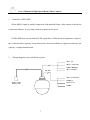
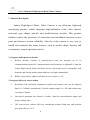
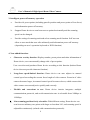
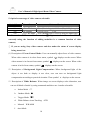
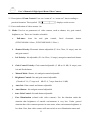
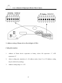
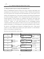
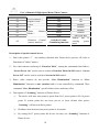
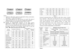
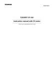
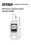
User’s Manual of High-Speed Dome Video Camera
I. Notice
1.
Before install and use the full-view High-Speed Dome Video Camera, please read this
user’s manual first.
2.
Power supply that the Dome device uses can adopt DC15V/1.5A or AC24V
(outdoor DOME). If use DC15V/1.5A, please make sure Dome device in normal
operation and load input voltage is around 15V and non-load input voltage is
1.5A. Otherwise, the video camera may operate out of order.
3.
Interior of the Dome device are precision optical and electrical instruments. Heavy
pressure, shock and other incorrect operations should be prevented during the
processes of delivery, storage and installation. Otherwise, may cause damage on
product.
4.
Please do not remove and disassemble any internal parts of Dome video camera by
self in order to avoid normal usage being impacted. There is no parts inside the device
which can be repaired by user self.
5.
During usage, user should abide by all electrical safety standards and adopt the special
power provided with the Dome video camera. During transmission, RS-485 and video
signal should be retained enough distance with high-voltage equipments or cables.
When necessary, thunder-proof, surge-proof and other protecting measures should be
carried out.
1
User’s Manual of High-Speed Dome Video Camera
6.
This device is for High-speed dome installation and use in order to avoid the Dome
video camera to be rained or be affected with humidity, etc. Please do not use the
product in humid place. If the video camera is installed outdoor, please make sure the
device being protected by sealed shield. The installation and use in open air without
any protection is forbidden.
7.
Please do not use the product under the situations of exceeding restrictive temperature,
humidity or power supply specifications.
8.
No matter whether power of the high-speed Dome video camera is connected or not,
please do not take the video camera aim at sun or very bright object and do not take
the video camera aim at or monitor bright static object for long time.
9.
Please do not use strong or caustic washing lotion to clean the main body of the
high-speed Dome video camera. After dirt is cleaned up, please use cotton fabric to
clean the product. When dirt is not easy to clean up, shall use neutral washing lotion to
clean and dry off gently.
10. Shall use the high-speed Dome video camera carefully and avoid being stroked or
shocked. If operating is improper, the product may be damaged.
11. When install the High-Speed Dome Video Camera, please install it in the place with
enough holding force.
2
User’s Manual of High-Speed Dome Video Camera
12. If camera lens adheres with dust, please use special lens paper to clean up.
13. When disassemble the Acrylic DOME shield, please wear cotton gloves to
process in order to avoid surface of the product being scraped.
II. Installation Instruction of Video Camera
1.
Remove Acrylic DOME shield (Please do not scrape the Acrylic shield. It is
recommended to wear cotton gloves when operate).
2.
As shown in the figure below, first take the flexible flat cable through connector
above the base plate and buckle it on the connector. Then buckle the cable on the
connection below the CAMERA.
3.
Lock the CAMERA up and fix the screws
Note: ① When install the CAMERA, please do not scrape the lens.
② After installed the camera and before being turned on, please test by manual to
confirm that the camera doesn’t touch the Acrylic or other parts. If touch,
please adjust the camera until it doesn’t touch anything then you can turn on.
3
User’s Manual of High-Speed Dome Video Camera
4.
Screw the CAMERA on according to the type of CAMERA.
YOKO( CNB)
HI TACHI
SONY
5. Install Acrylic shield
4- M5x15
Scr ew
4- M5x15
Scr ew
4- M4x8
Scr ew
φ 32
Br acket
4- M4x8
Scr ew
Out er Housi ng
I nner Housi ng
4- M3x6
Scr ew
Acr yl i c Hol der
4- M3x6
Scr ew
I nner Housi ng
Acr yl i c Hol der
Acr yl i c
Acr yl i c
Out door Dome
I nner Dome
4
User’s Manual of High-Speed Dome Video Camera
II. Install Bend-Tube-Style Bracket
60
100
φ 32
120
50
4- M5x15
Scr ew
310
4- M4x8
Scr ew
85
I nner Housi ng
Acr yl i c Hol der
Acr yl i c
I ndoor Dome
4- M5x15
Scr ew
4- M4x8
Scr ew
205
Br acket
196
I nner Housi ng
260
Out er Housi ng
Acr yl i c Hol der
Acr yl i c
Out door Dome
5
User’s Manual of High-Speed Dome Video Camera
III. Install Straight-Tube-Style Ceiling Bracket
186
3- M4x8
Scr ew
Cei l i ng
I nner Hous i ng
85
90
4- M3x8
Scr ew
Acr yl i c Hol der
Acr yl i c
IV. Description of Wiring
485+
Over Jmp
485-
485+
485RJ- 45
Moni t or
DC15V
6
User’s Manual of High-Speed Dome Video Camera
1. Terminal (OVER JMP)
When RS485 signal is parallel connected with multiple Dome video camera or when the
connection distance is very long, connection plate can be used.
OVER JMP short-circuit make RS-485 signal have 120Ω electrical impedance, improve
the communication capacity, avoid interference from miscellaneous signal and increase the
capacity of signal transmission.
2.
Wiring diagram of general Dome system
Moni t or
Mat r i x swi t cher
I mage manager s
RS- 485
Mul t i pl exer s
Mat r i x Swi t cher
Comput er
Power i nput
DC15V/ 1. 5A
Cont r ol l er
Al mbox
7
User’s Manual of High-Speed Dome Video Camera
V. Function Description
Indoor High-Speed Dome Video Camera is an all-in-one high-tech
monitoring product, which integrates high-definition color video camera,
universal gear change pan-tilt and multi-function decoder. This product
furthest reduces the processes of connection and installation between system
parts and increase system reliability. Also the video camera is very easy to
install and maintain, has many features, such as perfect shape, legerity and
convenience, simple operation and etc.
1. Integrate multi-protocol decoder
a.
Built-in decoder consists of multi-protocol and can integrate up to 16
communications protocols. Communication serial baud rate is adjustable. Using the
simple finger-switch inside the Dome device, the product can be compatible with
domestic and foreign main systems and has very high commonality.
b. RS485 serial control, address of Dome device is from 0~255.
2. Integrate full-view rotary station
a.
Horizontal 360º unlimited continuous rotation and rotation rate can be adjusted
from 0.5~240rad/s continuously. Vertical rotation range is 0~90º and rotation rate
can achieve 60rad/s.
b.
Low-speed operation has features of stable, ultra-low miscellaneous signal and
image without jitter.
c.
180º auto-reverse realizes full-view monitoring without blind area and position
precision achieves ±0.2°.
8
User’s Manual of High-Speed Dome Video Camera
3. Intelligent power-off memory operation
a.
Provides 64 preset points (including pan-tilt position and preset points of lens focus)
and information power-off memory.
b.
Support Dome device to scan between two points horizontally and the scanning
speed can be changed.
c.
Provide setting of scanning track and select scanning track function. Self-test can
allow to store track that user edits arbitrarily and information power-off memory.
(depending on user’s operation keyboard or DVR function)
4. New-added functions
a.
Character overlay function: Display number, preset points and other information of
Dome device, user can manually change title of preset points.
User can select and purchase Dome device according to this function (Indoor Dome
device does not provide character function).
b.
Long-focus speed-limited function: Dome device can auto adjusts its manual
control speed according the current focus length of video camera. Zoom-in of video
camera becomes larger, its manual control speed becomes slower, which ensures that
video camera can scan objective quickly and correctly.
c.
Flexible and convenient to use: Dome device interior integrates multiple
communication protocols, and serial transmission rate is selectable from 2400bps to
19200bps.
d.
Line-scanning position freely selectable: With different setting, Dome device can
scan between arbitrary two points with larger or less than 180°, and scanning speed is
adjustable continuously (related with communication protocols).
9
User’s Manual of High-Speed Dome Video Camera
5. Optical zoom range of video camera selectable
Optical Zoom
16x
18x
22x
23x
6. Use various
Focus Range
f3.9~f63mm
f4.1~f73.8mm
f4~f88mm
f3.6~f82.8mm
different video
Minimum Illumination
1Lux (F1.4)
1Lux (Normal type) / 0.01Lux (Day & Night type)
0.2 Lux (F1.6
1/3s)
1Lux (Normal type) / 0.01Lux (Day & Night type)
cameras: (■ represents the video camera being
currently using, the function of adding underline is a common function of video
camera)
□ If you are using Sony video camera and also under the status of screen display
being turned on:
(1) Description of Focus Control Mode: User can manually adjust focus of video camera.
When video camera is in close-focus status, symbol
video camera is in closest-focus status, symbol
camera is in far-focus status, symbol
displays on the screen. When
displays on the screen. When video
displays on the screen.
⑵ Description of Background Light Compensation: When background light of the
object is too dark or display is not clear, user can turn on background light
compensation according to practical situation. Then symbol
displays on the screen.
⑶ Description of White Balance: When image on screen displays color distortion, user
can set all kinds of mode by using commands and there are 6 modes selectable:
a.
Indoor Mode
b.
Outdoor Mode
c. Trigger Mode
d.
White Balance Auto-Tracking
e.
Manual
f.
Auto Mode
WB-MAN
10
ATW
User’s Manual of High-Speed Dome Video Camera
⑷ Description of Zoom Control: User can “zoom-in” or “zoom-out” lens according to
practical situation. Then symbol
displays on the screen.
⑸ Power indication of video camera: On
(6) Mode: Used to set parameters of video camera, such as shutter, iris, gain control,
brightness, etc. There are 9 modes selectable:
a.
Full-Auto:
Auto
iris
and
gain
control,
fixed
electronic
shutter
(FCB-IX48/480:1/60sec., FCB-IX48P/480P: 1/50sec.)
b.
Shutter Priority: Electronic shutter adjustable (F1.4 to Close, 18 steps), auto iris
and gain control
c.
Iris Priority: Iris adjustable (F1.4 to Close, 18 steps), auto gain control and shutter
d.
Gain Control Priority: Gain control adjustable (-3 dB to 18 dB, 18 steps), auto
iris and fixed shutter
e.
Manual Mode: Shutter, iris and gain control adjustable
f.
Brightness Control: Iris and gain control adjustable
(Closed to F1.6, 17 steps at 0
dB: F1.4, 7 steps form 0 to 18 dB)
g.
Auto Iris: Gain control and shutter adjustable
h.
Auto Shutter: Iris and gain control adjustable
i.
Auto Gain Control: Iris and shutter adjustable
j.
Zero Illumination (related with video camera): Use the function under the
situation that brightness of outside environment is very low. Under general
situation that video camera operates in auto status, when environment brightness is
less than 1Lux, then video camera will auto switch to zero illumination status and
11
User’s Manual of High-Speed Dome Video Camera
symbol
displays on the screen. Also user can manually switch the video
camera to zero illumination status.
k.
Mirror Image function: Left and right image is upside down.
l.
Static Image function: Image locks up certain image.
□ If you are using Hitachi video camera:
⑴
Description of Focus Control Mode: User can manually adjust focus of video camera.
⑵
Description of Background Light Compensation: When background light of the
object is too dark or display is not clear,
user can turn on background light
compensation according to practical requirement.
⑶
Description of Electronic Shutter: After video camera powered on, the device
initializes to fixed 1/50sec and digit 50 displays on the screen. When electronic shutter
of
video camera is in manual status, the adjustment range is: 1/3sec~1/10000 sec.
⑷
Description of White Balance: White Balance Auto-Tracking mode.
⑸
Description of Zoom Control: User can “zoom-in” or “zoom-out” lens according to
practical situation.
⑹ Power of video camera: On
⑺ Low Illumination: On/Off
⑻ AE Mode: Capable of switching between Manual/Auto
⑼ Iris: Capable of switching between Manual/Auto
⑽ Zero Illumination (related with video camera): Use the function under the situation
that brightness of outside environment is very low. Under general situation that video
camera operates in auto status, when environment brightness is less than 1Lux, then
video camera will auto switch to zero illumination status.
12
User’s Manual of High-Speed Dome Video Camera
⑾Mirror image function(related with video camera): Left and right image is upside
down.
□ If you are using Honeywell video camera or LG video camera (similar):
Refer to and compare with function of Sony video camera. With the function table setting,
user can easily adjust functions of video camera.
Note: Illustrative symbols specified above display only when screen turns on. When
screen turns off, only image displays on monitor.
Also user should notice: Functions of different model video camera may vary. When
choose and buy, user should make functions video camera clear.
13
User’s Manual of High-Speed Dome Video Camera
VI. Function Setting
1. Before Dome device is installed, please first make sure communication protocols
and serial transmission rate that control host in the system adopts.
On/Off
status
1st
digit of
Coding
switch
2nd
digit of
Coding
switch
3rd
digit of
Coding
switch
4th
digit of
Coding
switch
5th
digit of
Coding
switch
6th
digit of
Coding
switch
7th
digit of
Coding
switch
8th digit
of
Coding
switch
0
OFF
OFF
OFF
OFF
OFF
OFF
OFF
OFF
1
ON
OFF
OFF
OFF
OFF
OFF
OFF
OFF
2
OFF
ON
OFF
OFF
OFF
OFF
OFF
OFF
3
ON
ON
OFF
OFF
OFF
OFF
OFF
OFF
4
OFF
OFF
ON
OFF
OFF
OFF
OFF
OFF
5
ON
OFF
ON
OFF
OFF
OFF
OFF
OFF
6
OFF
ON
ON
OFF
OFF
OFF
OFF
OFF
7
ON
ON
ON
OFF
OFF
OFF
OFF
OFF
8
OFF
OFF
OFF
ON
OFF
OFF
OFF
OFF
9
ON
OFF
OFF
ON
OFF
OFF
OFF
OFF
10
OFF
ON
OFF
ON
OFF
OFF
OFF
OFF
11
ON
ON
OFF
ON
OFF
OFF
OFF
OFF
12
OFF
OFF
ON
ON
OFF
OFF
OFF
OFF
13
ON
OFF
ON
ON
OFF
OFF
OFF
OFF
14
OFF
ON
ON
ON
OFF
OFF
OFF
OFF
15
ON
ON
ON
ON
OFF
OFF
OFF
OFF
16
OFF
OFF
OFF
OFF
ON
OFF
OFF
OFF
17
ON
OFF
OFF
OFF
ON
OFF
OFF
OFF
18
OFF
ON
OFF
OFF
ON
OFF
OFF
OFF
19
ON
ON
OFF
OFF
ON
OFF
OFF
OFF
20
OFF
OFF
ON
OFF
ON
OFF
OFF
OFF
ON
ON
ON
ON
ON
ON
ON
ON
Address
of Dome
device
…
255
14
User’s Manual of High-Speed Dome Video Camera
2. Address setting of Dome device (first 8 digits of SW1):
Coding Description:
1. Address of Dome device represents as binary, where ON represents “1”, OFF
represents “0”.
2. Above coding only introduces 0~20 address codes, from 21 to 255 address coding
may be deduced by analogy.
3. Address coding range: 0~255
15
User’s Manual of High-Speed Dome Video Camera
3. Protocol Coding Match-up Table
(symbol ● represents that this protocol has been included):
On/Off
Status
Protocol
Type
Protocol Type
1st
Digit
2nd
Digit
3rd
Digit
4th
Digit
Default Serial
Transmission
Rate
5th
6th
Digit
Digit
Integr
ate
Protoc
ol
MGA01
OFF
OFF
OFF
OFF
OFF
ON
●
MGB01
*Sanli (Control
code of Sanli
matrix
from
COM1 port)
*PELCO-D
ON
OFF
OFF
OFF
ON
OFF
●
OFF
ON
OFF
OFF
ON
OFF
●
ON
ON
OFF
OFF
OFF
OFF
●
OFF
OFF
ON
OFF
Panasonic
ON
OFF
ON
Netac
OFF
ON
Hunda600
ON
Taiyo
*PELCO-P/4800
OFF
ON
ON
OFF
OFF
ON
OFF
○
ON
OFF
ON
OFF
●
ON
ON
OFF
ON
OFF
●
OFF
OFF
OFF
ON
OFF
ON
○
Vicon
ON
OFF
OFF
ON
ON
OFF
○
Molynx
OFF
ON
OFF
ON
ON
OFF
○
Kalate
ON
ON
OFF
ON
ON
OFF
○
Vcl
OFF
OFF
ON
ON
ON
OFF
○
Daiwa
ON
OFF
ON
ON
ON
OFF
○
Alec
OFF
ON
ON
ON
ON
OFF
●
Uitrak
ON
ON
ON
ON
ON
OFF
●
off
off
on
on
Off
On
Off
On
*PELCO-P/9600
Baud Rate
2400 bps
4800 bps
9600 bps
19200 bps
16
●
User’s Manual of High-Speed Dome Video Camera
4. Coding description of protocol and serial transmission rate:
When set communication protocol of Dome device (first 4 characters) and default serial
transmission rate of the protocol (last 2 characters of SW2), if default serial transmission
rate of the protocol does not match with serial transmission rate of host, please set the
default serial transmission rate of the protocol consistent with default serial transmission
rate of host according to Appendix 3. Above lists protocols that are suitable for the device.
Normal operations of these protocols are compatible with domestic and foreign main
systems. There into, for some special protocols, such as “Sanli Protocol”, “PELCO-D”,
“PLECO-P”, “Ultrak”, etc, some special functions has no corresponding operation
command specified in these protocols. To allow user can use some special functions of the
product conveniently, we switch functions of some normal commands in order to achieve
the objective of controlling special functions of intelligent Dome device. Under general
situation, we adopt “Enable preset point/Set preset point command” to switch functions.
Below, we list contents of command switch.
Match-up control method table is shown below:
N
SN Number
Definition of Keyboard Operation
Enable No. N Preset Set No. N Preset
Point
Point
Enable
line-scanning
Enable scanning
(low-speed)
Enable
line-scanning Set starting point
(medium-speed)
of scanning
Enable
line-scanning Set ending point of
(high-speed)
scanning
Control Object
51
52
Pan-tilt
Compensation
Control
53
54
55
56
Video
Camera
Power Control
Background Light
Compensation *
Zero Illumination
17
Power On
Power Off
On
Off
On
Off
User’s Manual of High-Speed Dome Video Camera
57
58
59
60
61
62
63
64
Screen Display *
Digital Zoom *
Focus
Iris
White
Mode *
On
On
Auto
Auto
Auto
Indoor
ATW
Balance
Character Control
(choose and but)
Switch to FrameCumulating function
Off
Off
Manual
Manual
Manual
Outdoor
One Push WB
Modify title of
existing
preset
point
Description of special control above:
1、 Item with symbol “*" has memory function after Dome device powers off (refer to
Functions of Video Camera)
2、 For video camera consisting of “Function Table”, among the commands listed above,
“Screen Power On” can be used to switch to Function Table On/Off control. “Screen
Power Off” can be used to switch to Screen On/Off control.
3、 Some video cameras do not provide “Zero Illumination” function or “Zero
Illumination” function is auto switched and it is not controlled by command. Then
command “Zero Illumination” specified above does make any effect.
4、 Description of “Scanning” function of Dome device:
①
The device will auto scan point by point from No.1 preset point to No.16 preset
point. If certain point has not been pre-set or been cleared after preset,
“Scanning” will not scan these points.
②
Residence time between two preset points is 4 seconds.
③
By setting No.51 preset point, the device can carry out “Scanning” function of
Dome device.
18
User’s Manual of High-Speed Dome Video Camera
5、 Description of “Line-Scanning” function of Dome device:
① Dome device will auto line-scan between two specified points.
② Speed of line-scanning contains 3-level. By adopting No.51, No.52, and No.53
preset points, the device can start line-scanning function by 15degree/sec,
5degree/sec and 10degree/sec respectively.
③ Residence time of line-scanning between “starting point” and “ending point” is 3
seconds.
6、 Because set/adopt functions of No.51~64 preset points have been changed to other
control functions, so storage range of preset point is 1~50 and there are totally 50
preset points.
7、 Above is compensatory description to control of high-speed Dome video camera.
Original operation methods of its control system do not change.
Below give an example of PECOL_D keyboard and operation instructions of part special
function are shown:
⑴ Set preset point:
①
②
Press the button of necessary digits, select present number for setting
Press SET PRESET button
⑵ Adopt preset point:
①
Press the button of necessary digits, select present number for setting
②
Press CALL PRESET button
⑶ Line-scanning setting between two points:
①
Change pan-tilt to position of starting point for scanning.
②
Press digit key 52
19
User’s Manual of High-Speed Dome Video Camera
③
Press SET PRESET button
④
Change pan-tilt to position of ending point for scanning.
⑤
Press digit key 53
⑥
Press SET PRESET button
⑷ Line-scanning startup between two points:
①
Press digit key 51(52、53)
②
Press CALL PRESET button
③
Dome device carries out line-scanning by 1st-level (2nd-level, 3rd-level)
④
If starting point is the same as ending point, the device will carry out 360° scanning.
⑸ Scanning operation (deal with those operating system that cannot set tracking):
①
Press digit key 51
②
Press SET PRESET button, the device will scan point by point from No.1 preset
point to No.16 preset point and residence time in each preset point is around 4
seconds.
⑹ Preset point title editing (Dome device without character display does not provide this
operation function)
①
Turn on screen display (if screen display is in on status, then don’t need to perform
this operation). Press digit key 57. Then press CALL PRESET button.
②
Adopt preset point of the title for editing. Press the button of necessary digits, select
number of the preset point for adopting
③
Press digit key 64
④
Press SET PRESET button, 1st character of the title for editing will flash
⑤
Utilize joystick “Up Down/Left Right” to edit the title
20
User’s Manual of High-Speed Dome Video Camera
⑥
After editing is completed, press digit key 64
Press SET PRESET button to quit character editing status.
⑺ Iris Control (Note: if iris is in auto status, then iris may be not controllable)
① Change iris to manual mode (if iris is already in manual status, then don’t need to
perform this operation)
a. Press digit key 60
b. Press SET PRESET button, then iris changes to manual mode
② Press OPEN/CLOSE button, then can change iris size
③ Once joystick is enabled, iris will switch manual to auto
⑻ During the processes of “Line-Scanning” and “Scanning”, the device can respond
alarm information. During the process of “Line-Scanning”, user can control video
camera. By controlling joystick, user can cancel “Line-Scanning” and “Scanning”.
21
User’s Manual of High-Speed Dome Video Camera
VII. General Failure Analysis Table
Problem Description
After power on, no motion
and no image.
Self-test is exceptional,
there is image but with
motor noise “wu”.
Self-test is normal, but
there is no image.
Self-test is successful, but
can’t control.
Image is not stable.
Dome device
controllable.
is
not
Iris of the Dome device is
not controllable.
Possible Reason
Power supply module is
damaged or power is not
enough.
Power cable is connected
improperly.
Failure
occurs
on
engineering line.
Mechanism failure.
Video camera is slantwise.
Power is not enough.
Video line is connected
mistakenly.
Video line is poor contact.
Video camera is damaged.
Control signal line is
connected mistakenly.
Position of Dome device
does not match.
Protocols are not matched.
Video line is poor contact.
Power is not enough.
Self-test is exceptional.
Control signal line is poor
contact.
Operation of Host has
problem.
Too
much
load
or
communication distance is
too long.
Iris is in manual status.
22
Troubleshooting
Change
Correct
Eliminate
Examine and repair
Put right
Change power that meets
requirements.
It
is
recommended to place the
power switch near the Dome
device.
Correct
Eliminate
Change
Correct
Re-select
Adjust the protocols being
match with the controller.
Re-power on.
Eliminate
Change
Re-power on
Eliminate
Re-power the host on
1. Confirm
terminal
resistance
2. Add code distributor
Use control command to set
iris to manual status and iris
can be controlled.
User’s Manual of High-Speed Dome Video Camera
VIII. Main Technical Indexes
Specification
Function of
Video Camera
Image sensor
1/4” Color CCD
Effective Pixel
752H×582V (440000pixels)
Synchronization
System
Internal synchronization
Video Output
Composite signal 1.0Vp-p/75Ω
White Balance
Auto/Manual
Power
AC24V ±10%
Power
Consumption
18VA
Weight
2Kg
0℃~40℃ (normal range)
Signal-to-Noise
About 48DB
Zoom Range
Parameter of
Lens
Basic
Function of
Dome Video
Camera
2A
Installation
Method
Relative
Temperature
Operating
Temperature
Scanning
System
Horizontal
Resolution
Electronic
Shutter
Minimum
Illumination
PAL
Ceiling-style, hanging-type ceiling-style, etc
10-75% (under
agglomeration)
15.625KHz(H)
the
condition
of
without
50Hz(V)
480 TV lines (depending on different model of video
camera)
1/3~1/10000sec
0.01~1Lux(F1.6) (depending on different model of
video camera)
16x, 18x, 22x, 23x, 25x optical zoom and 4x digital
zoom (depending on different model of video camera)
Iris
Auto/Manual
Zoom
Auto/Manual
Horizontal Shift
0~240°/s
Vertical Shift
0~60°/s
Preset
64
Scanning
Function
Store up to 6 scanning tracks (depending on different
protocols)
23