1
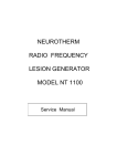
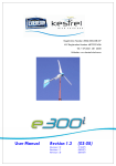
NT-500™
Technical Support Guide
For use by qualified company approved
Technicians
Version 2.0
October 2007
INTRODUCTION
The NT-500 is designed to offer the full range of features required to perform
radiofrequency denervation
The front panel has been ergonomically designed and allows the clinician direct
manipulation of the controls. Each functional effect of the device is defined within its
own discrete area.
The NT-500 is designed for safe use in the Doctors office, Surgery Centre or Hospital
environment.
Linear bar displays are used to give immediate visual interpretation of the
temperature, RF current and RF Voltage, and digital displays are used for impedance,
stimulate voltage and lesion time.
The NT-500 has full electronic interlocking to prevent accidental switching to lesion
power and stimulation voltage.
Note: The Machine has been factory set and should not be adjusted except by Approved
technicians authorized by the company.
The Machine has been designed to work with NT-500 thermocouple probes only. The
use of probes from other manufacturers could give serious errors in the temperature
reading and may compromise the safety of the patient, and would negate the warranty.
Regularly inspect the NT-500 accessories in particular the electrode cables should be
checked for possible damage to the insulation.
Please note the warning information in the NT-500 User Manual before attempting to
carry out any service or maintenance to the machine.
Any Maintenance or Service must only be carried out by Qualified
Technicians Approved by the Company.
Version 2.0
October 2007
Basic Fault Diagnosis
1) No power to the NT-500
Check the power inlet cable is connected to the wall socket and switched on.
If the cable has fused power plug, check the fuse in the power plug.
IEC Fuse carrier
2) No power to the NT-500
Check the fuses in the IEC mains power inlet fuse carrier
For 110 volt units the fuse should be 2 X 2 amp fused on the Live and Neutral
Type T2H Bussman
For 230 volt units the fuse should be 2 X 1 amp fused on the Live and Neutral
Type T1H Bussman
If a fuse is faulty change the fuses
Only use this type of fuses as a replacement on this machine
Internal Fuses
Picture of NT-500 fuse card
Version 2.0
October 2007
The NT-500 has a set of internal fuses that can be accessed by qualified company
approved technicians.
Remove the 4 cover Allen screws with a 3mm hex key on the rear of the NT-500,
to expose the rack of Printed circuit boards.
Using a crosshead screwdriver remove the two screws retaining the Printed
Circuit Board clamp bar. Remove the clamp bar for access to the PCB rack.
The Fuse PCB is the far left hand side of the rack looking at the rear of the NT500.
Turn on the power to the NT-500 and check if the 4 Green LED’s are illuminated.
If all LED’s are lit the problem is not a fuse blown, replace the retainer bar and fix
in place with the two crosshead screws. Replace the cover and contact
NeuroTherm Technical Support Department to report the suspected fault.
If one of the fuse indication LED’s is not illuminated a fuse has blown.
Switch off the mains power switch and remove the power cord before, removing
the Fuse PCB. Pulling the handle of the card to remove it from the rack.
To check fuses
1) Visually inspect the fuses for signs of a blown fuse
2) If a fuse is blown only replace with the correct rating fuse
(Type T anti-surge Bussman S506)
F102 1 Amp
F103 1 Amp
F104 1 Amp
F105 3.15 Amp
3) Check continuity of each fuse (with an ohmmeter or buzzer)
4) Ensure each fuse is secure in the fuse holder clips
5) After replacing fuse refit plastic protective covers
Refit the Fuse PCB into the card rack and connect the power cord to the
NT-500, turn on the mains switch on machine.
If the unit does not work and the fuse has blown again contact
NeuroTherm Technical Support Department.
If the fuse replacement has solved the problem switch off the mains switch
and remove the power cord.
Check that all the PCB’s are pushed fully home in the card rack.
Replace the retainer bar and fix in place with the two crosshead screws.
Replace the cover and fix into place with the 4 Allen Hex screws
Carry out the Test of function as described in the next section
3) Test of Functions
Version 2.0
October 2007
The NT-500 is a reliable and well proven Lesion Generator, if any problem is
suspected, the following test should be carried out to check the functionality of the
Machine
3)
Test of Functions
1) Turn Mains Switch ON
The Mains Green LED on the front Panel will
light up. (If the Mains Green LED fails to light
check the fuses- fuses are located in the Mains
Inlet Module and behind the rear panel of the
machine on the Fuse Board).
The Standby LED will be lit and the impedance
Display will indicate a value in ohms
2) Connect the Probe to the right hand Front
Panel Socket
The Thermocouple LED will change from Red to
Green showing the Probe is connected and
operating.
3) Press the Lesion Button on the Front
Panel
The Lesion Button LED will light together with
80ºC Button LED and the Time Start LED.
The temperature display will be active and will
show if temperature is above 30ºC.
4) Turn the RF Power Control clockwise
The Time Display should display 60 seconds
5) Press the Timer Start Button
The RF Voltage Display shows Voltage being
present (if the display fails to show check the 75V
Fuse on the Fuse Board.) The Amber Lesion
Power LED will flash.
The Time Start LED should flash; the machine
will count down in 1 second increments from 60
seconds shown in Timer Display. When the timer
reaches 0 the Voltage Display, will turn off and
an alarm will sound.
6 ) Turn the RF Power Control fully
counter - clockwise
7) Check the Stimulate Mode by pressing
the Stimulate Button
Version 2.0
The alarm will cease.
The Stimulate and Sensory Button LED's will
light and the Stimulate Display should indicate
Voltage.
October 2007
8) Turn the Stimulate Control Clockwise
The Stimulate Voltage should display up to 3.0
volts and Sensory Button LED should flash at
50Hz. or 100Hz (When Motor is selected the
flash rate is 2Hz)
9) Turn the Stimulate Control Fully
Anticlockwise
The Stimulate Display should read 0.0 volts and
any flashing should cease.
10) Press the Standby Button
Testing of the NT-500 is now complete and
machine is ready for use.
Common Problems and Solutions
4)
No temperature reading on the Thermocouple electrode
Check the electrode for any visual defect to the cable or electrode
Plug the electrode cable into the NT-500, turn on the machine and set the
machine to lesion mode. Ensure that the thermocouple LED changes from red
to green, if it stays red the thermocouple is faulty. (Change the Thermocouple
Electrode)
To check temperature, place the electrode tip into water at 50ºC approximately
to see if the temperature display changes to the water temperature.
If not working Change to a new Thermocouple Electrode
Redo the temperature test as section 4)
If no Temperature reading Contact NeuroTherm Technical Support
Department
5)
No stimulation voltage
To check stimulation
Select Stimulate button and then the (Sens100Hz) button
Using the NT-500 TEST BOX
Connect the Active output and the Dispersive output connectors from the Test
box into the NT-500
Connect an oscilloscope to the Active and Dispersive test points on the test
box and set the oscilloscope to read 200 mv/div at 1.0ms time base.
Rotate the stimulate control fully clock wise check that the output pulse
measures approximately 3.2 volts on the negative pulse. The NT-500 display
should show this voltage.
The frequency is 100 Hz (10ms) with pulse width of 1ms.
If the Stimulate Functions works on the test box check the electrode and the
dispersive lead to see if they have failed.
If the Stimulate does not work with the test box contact NeuroTherm
Technical Support Department.
Version 2.0
October 2007
6)
No RF Power Output
To check for RF output
With the NT-500 TEST BOX connected to the Active and Dispersive
connectors, set the NT-500 to Lesion Mode by pressing the Lesion button, and
connect an oscilloscope to the test points on the test box.
Set the oscilloscope to 20 volts /div and 1.0ms time base
Rotate the RF power control 50% anticlockwise check the RF power is
displayed on the oscilloscope. Check that the NT-500 display LEDS show
Voltage and Current. This will display 5 LED’s Volts and 1 LED for current
approximately.
If RF power is displayed on the oscilloscope check the electrical continuity of
the Patient Dispersive cable. (Approximately 0.5 Ohm) and the Electrode lead
for a failure
If no RF Power at test box Contact NeuroTherm Technical Support
Department
7)
Pulsed RF output Check
With the NT-500 TEST BOX connected to the Active and Dispersive
connectors, set the NT-500 to Pulsed RF mode by pressing the Pulsed button.
Connect an oscilloscope to the test points on the test box.
Set the oscilloscope to 5.0 volts /div and 10.0ms time base
Rotate the RF power control fully anticlockwise check the Pulse burst of RF
power (20ms) is displayed on the oscilloscope. Check that the NT-500 display
LED’s show Voltage and Current. This will display 8 LED’s Volts and 2
LED’s for current.
If pulsed RF power is displayed on the oscilloscope check the electrical
continuity of the Patient Dispersive cable. (Approximately 0.5 Ohm) and
check the electrode
If no Pulsed RF Power at test box Contact NeuroTherm Technical
Support Department.
8)
Patient connection Problems
No stimulation felt by patient
a) Is the dispersive lead connected to the patient correctly
b) Is the dispersive pad the correct size (16sq inches surface area)
c) Is the dispersive cable connected to the NT-500
d) Is the electrode connected to the input socket
e) Is the electrode the correct length for the Cannula (is the electrode tip
visible at the tip of the Cannula)
f) Ensure that NeuroTherm electrodes are being used
Version 2.0
October 2007
9)
RF Lesion
Will not reach the set temperature
a) Dispersive lead connected correctly to patient
b) Dispersive lead not plugged into NT-500
c) Electrode too short for the Cannula (check that you can see electrode
tip in the Cannula)
d) Cannula placed in an area of the patient close to an artery (this can
have a cooling effect due to high blood flow limiting the temperature)
e) Check the impedance reading of the patient (400 – 1000 ohms) average
f) Try a new electrode and Cannula
10) Pulsed RF
Does not reach set temperature
Pulsed RF does not have to reach the set temperature as this is not a
thermal lesion, if the temperature does reach the set temperature the NT500 will reduce the width of the 20ms burst of RF until the temperature is
1 ºC below the set temp. The NT-500 will then supply the full 20ms burst
of RF power.
11) Pulsed Dose Option
An option of the NT-500 is to have a Pulsed Dose RF facility.
Pulsed Dose RF ensures that the number of full 20ms width pulse burst is
delivered to the patient. Instead using a time period the Pulsed Dose supplies
the correct number of pulse bursts to the pre-selected count number.
The control of the temperature is done by stopping the RF pulse burst and the
counter when the temperature exceeds 42ºC.
When the temperature drops by 1ºC the counter and the RF pulsed dose will
resume at the full 20ms pulse burst.
This will continue until the count reaches zero, the power will switch off and a
warning tone will sound.
12) To Test pulsed Dose
Using the NT-500 TEST BOX connected to the Active and Dispersive
connectors, set the NT-500 to Pulsed Dose Mode press the pulsed button.
Plug a Thermocouple electrode into the test box and leave at ambient
temperature. Check that the LED changes from red to green.
Connect an oscilloscope to the test points on the test box.
Set the oscilloscope to 5.0 volts /div and 10.0ms time base
Check that the default count setting is 240 pulses
Rotate the RF power control to display 45 volts press the start button and
check the Pulse burst of RF power (20ms) is displayed on the oscilloscope
and the counter is counting down.
Place the electrode tip into water that has a temperature just above 42ºC to
45ºC the RF pulse burst will stop and so will the counter.
Remove the electrode from the warm water and as the electrode temperature
goes below 42ºC the pulse burst and the counter will re-start.
If the Pulse Dose does not stop the count and the RF Pulse burst with a
Temperature of 45ºC contact the NeuroTherm Technical Support
Department.
Version 2.0
October 2007
Technical Support
The CHECK AND TEST PROCEDURE should be routinely performed each
time the NT-500 is used. A periodic full service on an annual basis is
recommended.
The Operator Must Not Perform any Servicing of the Equipment
Maintenance must only be carried out by suitably trained and qualified
personnel authorized by the Company
In the event of the NT-500 malfunctioning, you should immediately contact.
In the USA
NeuroTherm Inc
2 De Bush Ave. Suite A-2
Middleton
MA01949
USA
Tel: 978 777 3916
Fax: 978 777 5121
[email protected]
OR in the UK
NeuroTherm Ltd.
429 Brighton Road
Croydon
Surrey CR2 6EU
Tel: +44 (0)208 660 4374
Fax: +44 (0)208 660 9417
[email protected]
Version 2.0
October 2007