1
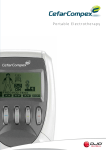
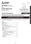
InToneTM User Manual PN: 2009000C1_3 InTone User Manual (2009000C1_3) Effective Date:12/6/12 Page 1 of 24 Copyright 2011 by InControl Medical, LLC All Rights Reserved. No part of this work may be reproduced or copied in any form or by any means without written permission from InControl Medical, LLC. InControl Medical, LLC Brookfield, WI 53045 USA www.incontrolmedical.com InTone User Manual (2009000C1_3) Page 2 of 24 Table of Contents Preface ....................................................................................................... 5 Overview ................................................................................................................................................. 5 Intended Use ........................................................................................................................................... 5 Intended Audience................................................................................................................................... 5 Contact Information ................................................................................................................................. 5 Product Warranty .................................................................................................................................... 5 Symbols Used .......................................................................................................................................... 6 Warnings, Cautions and Notes .................................................................................................................. 6 Contraindications..................................................................................................................................... 8 Chapter 1.................................................................................................. 10 Equipment Overview ............................................................................................................10 Control Unit ........................................................................................................................................... 10 Insertion Unit ........................................................................................................................................ 11 PC Cable ................................................................................................................................................ 11 Chapter 2.................................................................................................. 12 Setting up the Components ...................................................................................................12 Connecting the Insertion Unit to the Control Unit .................................................................................... 12 Disconnecting the Insertion Unit from the Control Unit ........................................................................... 12 Charging the Battery .............................................................................................................................. 13 Cleaning the Insertion Unit ..................................................................................................................... 13 Chapter 3.................................................................................................. 14 Using the System ...................................................................................................................14 This chapter provides instructions for using the InTone System. It includes both therapeutic treatment and biofeedback use instructions. ....................................................................................... 14 Patient Use ............................................................................................................................................ 14 Chapter 4.................................................................................................. 16 Testing and Servicing the System .........................................................................................16 Chapter 5.................................................................................................. 17 Troubleshooting the System .................................................................................................17 InTone User Manual (2009000C1_3) Page 3 of 24 Troubleshooting the Insertion Unit and Control Unit ............................................................................... 17 Chapter 7.................................................................................................. 19 Specifications ........................................................................................................................19 Control Unit ........................................................................................................................................... 19 Insertion Unit ........................................................................................................................................ 20 Computer Connection ............................................................................................................................ 20 AC Charger ............................................................................................................................................ 21 Environmental Conditions ...................................................................................................................... 21 Electromagnetic Imunity ........................................................................................................................ 22 Electromagnetic Imunity ........................................................................................................................ 23 Intentionally Blank ................................................................................................................................. 24 InTone User Manual (2009000C1_3) Page 4 of 24 Preface Overview TM The InControl InTone device includes three parts; an inflatable Insertion Unit for intra-vaginal use, a hand-held Control Unit and a PC application for the clinician to program the hand-held device. This guide TM provides procedures for setting up and using the InControl InTone device. Intended Use TM The InControl InTone device is a non-implanted electrical stimulator indicated for use in the treatment of female urinary incontinence. It applies electrical stimulation to the pelvic floor musculature and surrounding structures. It is intended for acute and ongoing treatment of mixed urinary incontinence where the following results may improve urinary control: strengthening of pelvic floor muscles and inhibition of the detrusor muscle through reflexive mechanisms. The biofeedback feature can be used for re-education purposes. Intended Audience TM The InTone User Manual is intended for users of the system, including care providers and patients. The product is intended to be used under the direction of the care provider. Contact Information For more information about InControl products, go to www.incontrolmedical.com. For technical support, questions or comments about documentation, contact (262) 373-0422. Product Warranty InControl Medical, LLC will offer a 1 year warranty on the InTone TM device for defects in workmanship. Definitions: Muscle Stimulation: InControl Medical defines electrical stimulation of the pelvic floor musculature as “muscle stimulation” in this manual. InTone: InControl Medical, LLC defines InControl InTone Page 5 of 24 TM as InTone. InTone User Manual (2009000C1_2) Symbols Used The following symbols are used in this manual or on the product. Attention! Please follow the instructions in the User Manual. Type BF applied part. Internally powered. The Control Unit can be damaged by ElectroStatic Discharge. The pins of the Control Unit connectors should not be touched unless ESD precautions are taken. The Insertion Unit can be damaged by ElectroStatic Discharge. The pins of the Insertion Unit should not be touched unless ESD precautions are taken. Warnings, Cautions and Notes Warnings, Cautions and Notes are used in this manual. A Warning is used when failure to follow the instructions may result in injury or device damage. A Caution is used to minimize risk. Notes are used to provide clarification or advice. Caution: Federal law restricts this device to sale by or on the order of a physician. Warning: Muscle stimulation is one part of a total therapy program. It is meant to be used in conjunction with counseling and feedback. Do not undertake therapy without the advice of a care provider. TM Warning: Do Not use a charger other than supplied by InControl Medical, LLC for the InTone device. The incorrect charger can result in damage to the unit. Warning: Read all instructions prior to use. Failure to follow these directions may result in personal injury or damage to the equipment. InTone User Manual (2009000C1_3) Page 6 of 24 Warning: Only use approved antiseptics that leave no residue. Warning: The InTone is intended for indoor use only. Exposure of the Control Unit to liquids may cause personal injury or equipment damage. Warning: Therapy is defined on an individual basis, dependent on the patient's symptoms and condition. Do not undertake or alter therapy recommendations without the advice of the care provider. Warning: If tissue irritation occurs, discontinue treatment immediately. Ask your care provider for advice before continuing further treatment. Warning: Do not use an Insertion Unit or Control Unit that appears to be damaged. Using a damaged device may result in personal injury. Warning: Do not operate device within 10 feet of operating televisions, arc welders, radio thermal treatment equipment, X-ray machines, MRI machines, or any other equipment that produces magnetic fields, sparks, or radio transmissions. RF communications equipment can affect this device Warning: Explosion hazard: Do not use in the presence of flammable anesthetics, nitrous oxide, or oxygen enriched environments. Warning: Take care in arranging patient and cables to avoid risk of entanglement, tripping, or strangulation. Warning: Use of any equipment should be discontinued upon any signs of treatment related stress or discomfort. Warning: The device should not be used while walking, driving, operating machinery, or any other activity in which involuntary muscle contraction may put the user at risk. Warning: Do not use the device while in the bath, swimming, or otherwise submerged. InTone User Manual (2009000C1_3) Page 7 of 24 Warning: The long-term effects of chronic muscle stimulation are unknown. Caution: Caution should be used for patients with suspected or diagnosed heart problems. Caution: Caution should be used for patients with suspected or diagnosed epilepsy. Caution: Caution should be used when there is a tendency to hemorrhage following acute trauma or fracture. Caution: Electrode placement and stimulation settings should be based on the guidance of the prescribing practitioner. Caution: Patients with a total/partial prolapse of the uterus/vagina must be stimulated with extreme caution. Caution: Patients with urethritis must be treated before commencing stimulation. NOTE: InTone is a single patient use device. Contraindications Do Not Use if you have the following: Pregnancy or attempting to become pregnant (patients should be six weeks post-partum) Cardiac pacemaker, implanted defibrillator, or other implanted metallic or electronic device. Do not use if you have a history of rate or conductive disturbance. Active cancer Active vaginal infection, open sores or urinary tract infection Recent pelvic surgery (patients should be 6 weeks post-operative & have their doctor’s clearance) Dementia Complete denervation of the pelvic floor Inability to position Insertion Unit according to guidelines provided Irregular menstrual bleeding cycles History or symptoms of urinary retention, extra-urethral incontinence, overflow incontinence InTone User Manual (2009000C1_3) Page 8 of 24 Intestinal clamp InTone User Manual (2009000C1_3) Page 9 of 24 Chapter 1 Equipment Overview This chapter provides an overview of the equipment included in the InTone System. The InTone System includes three parts. Control Unit Insertion Unit Control Unit The Control Unit is a hand-held device used to initiate and guide treatment sessions while recording and storing results of muscle stimulation and patient generated pelvic floor exercises. The PC-based software application allows the clinician to customize the stimulation for each patient and displays the results of prior sessions. The Control Unit has the following features and functions: Provides customizable stimulation necessary to stimulate pelvic floor contraction Measures and records pressure generated by patient pelvic floor exercises Provides visual biofeedback to encourage pelvic floor muscle activation Displays contraction force Allows downloading of data to personal computer through custom USB cable Provides audible directions to guide the patient through the exercise program Provides single key pause to discontinue muscle stimulation if necessary Control Unit Page 10 of 24 InTone User Manual (2009000C1_2) Control Unit Insertion Unit Insertion unit Inflation Bulb Air Release Valve Stimulation Contacts Insertion Unit The Insertion Unit is an inflatable probe for intra-vaginal use. The unit has a patented inflation bulb and air release valve to customize the fit. The Insertion Unit connects to the Control Unit through a flexible connection. The Insertion Unit has the following features and functions. Provides manual inflation of balloon to fill the vagina to a comfortable level When inflated, provides full contact of stimulation contacts to vaginal wall Provides programmed muscle stimulation of pelvic floor muscles Ability to clean with common, commercially available cleaners PC Cable The PC Cable allows the Control Unit to be connected to the USB port of the clinician’s computer. This connection allows the transfer of data to the PC. The unit cannot be used while it is connected to the PC. Users will not be able to connect the Control Unit to a personal computer. InTone User Manual (2009000C1_3) Page 11 of 24 Chapter 2 Setting up the Components This chapter provides procedures on how to set up the InTone System for use. The components in the InTone System are provided as a kit, consisting of assembled units and parts. These kits should be kept together until you are ready to use them. Warning: Read all instructions prior to use. Failure to follow these directions may result in personal injury or damage to the equipment. Caution: Federal law restricts this device to sale by or on the order of a physician. Warning: Muscle stimulation is one part of a total therapy program. It is meant to be used in conjunction with counseling and feedback. Do not undertake therapy without the advice of a care provider. Connecting the Insertion Unit to the Control Unit 1. Align the connectors of the Insertion Unit and Control Units. The DB-9 connector is on the bottom of the Control Unit. 2. Gently press the connector into place. DB-9 connector Disconnecting the Insertion Unit from the Control Unit 1. Gently pull the DB-9 connectors apart. Tip: Do not touch the conductors in the connector. This could cause damage to the pins or Control Unit. InTone User Manual (2009000C1_3) Page 12 of 24 Charging the Battery The battery should be charged when the green battery indicator light starts to flash. 1. Disconnect the Insertion Unit. 2. Connect the wall charger to the Control Unit and wall power outlet. The green battery indicator light will flash during charging. 3. When charging is complete the green battery indicator light will be constantly illuminated. Unplug the cable from the Control Unit. Tip: Ensure battery is charged prior to use. Control Unit cannot be used when the USB cable is connected. Warning: Do Not attempt to use a charger other than supplied by InControl Medical, LLC for the InTone System. The incorrect charger can result in damage to the unit. Cleaning the Insertion Unit Following use, the Insertion Unit should be cleaned. The insertable portion of InTone is easily cleaned using soap and water, isopropyl alcohol, hydrogen peroxide (less than 10%) or sodium hypochlorite (less than 10%). 1. Turn off the Control Unit. 2. Disconnect the Insertion Unit from the Control Unit. 3. Inflate the Insertion Unit and wipe clean with recommendations above. Do not soak. 4. Rinse and dry thoroughly. Tip: Do not attempt to fill the Insertion Unit with water or any other liquid. If water enters the Unit, thoroughly dry prior to re-use. Warning: Only use approved antiseptics that leave no residue. Do NOT soak. InTone User Manual (2009000C1_3) Page 13 of 24 Chapter 3 Using the System This chapter provides instructions for using the InTone System. It includes both therapeutic treatment and biofeedback use instructions. Warning: The InTone System is intended for indoor use only. Exposure of the Control Unit to liquids may cause personal injury or equipment damage. Muscle stimulation and biofeedback are treatments used to train and strengthen the pelvic floor muscles in a controlled manner. Muscle stimulation is used to improve the ability of muscles to hold a contraction for an extended period of time and is a treatment for urinary incontinence in conjunction with exercise and biofeedback. During a session, impulses are delivered to specific muscles to stimulate their contraction. This contraction exercises the muscles and also helps the patient recognize which muscles to condition. Voice-guided pelvic floor exercises are complemented with biofeedback to provide visual confirmation of the patient's voluntary muscle contractions. Biofeedback enhances the efficacy of pelvic floor exercises. Warning: Therapy is defined on an individual basis, dependent on the patient's symptoms and condition. Do not undertake or alter therapy recommendations without the advice of the care provider. Warning: If tissue irritation occurs, discontinue treatment immediately. Ask your care provider for advice before continuing further treatment. Patient Use A quiet, private place is recommended to aid relaxation. Many women prefer to do their sessions while in bed. 1. Connect the Control Unit to your Insertion Unit and have InTone gel available. 2. Position with knees bent and pelvis flat to begin your InTone session. Many women find it is comfortable to do so in bed with 2 pillows to support their back and shoulders. 3. Press the power key and follow the voice guided instructions. NOTE: When powering on your InTone system your stimulation setting will display briefly InTone User Manual (2009000C1_3) Page 14 of 24 NOTE: When inflating your device press inflation bulb and inflate balloon until Control Unit displays your inflation pressure number given to you by your clinician. NOTE: The bar graph reflects contraction force. The display reflects the timing of contractions relative to the voice commands. During stimulation session the display will countdown as the 5 minute session progresses (5,4,3,2,1). 4. Clean the Insertion Unit and allow to air dry. Warning: Do Not remove Insertion Unit without the device powered off and deflated. Tip: Treatment can be paused at any time by pressing the pause key. The interrupted session can be restarted by pressing the pause key again. If the session is not restarted within five minutes, the device will turn off. Tip: Volume can be adjusted by using the Press the InTone User Manual (2009000C1_3) up/down arrow keys. Page 15 of 24 Chapter 4 Testing and Servicing the System This chapter provides procedures to test the InTone System prior to use. It is important to test the overall functionality of each component prior to putting the system into service. Additionally, it is important to periodically verify the continuing proper operation of each component. Tip: You should test all of the system components prior to use to verify proper operation. Warning: Do not use Insertion Unit or Control Unit that appears to be damaged. Using a damaged device may result in personal injury. 1. Visually inspect the Insertion Unit, Control Unit, and connectors for damage. 2. Connect the Insertion Unit to the Control Unit. 3. Turn on the Control Unit. 4. An error will be displayed if the connection is not complete. InTone User Manual (2009000C1_3) Page 16 of 24 Chapter 5 Troubleshooting the System This chapter provides procedures on how to service and troubleshoot the InTone System. If you have consistent issues with the system, please contact InControl Technical Support at 1-262-373-0422. Troubleshooting the InTone System Prior to use or any troubleshooting: 1. Verify that the Control Unit battery is charged. If the low battery indicator is shown, recharge the battery. 2. Inspect the Insertion Unit for damage. If the silicone covering or any cables appear damaged, the unit must be replaced. 3. Disconnect the Insertion Unit from the Control Unit. Inspect the connectors for damage. If the pins are not straight, or otherwise appear damaged, the unit must be replaced. 4. Carefully reconnect the Insertion Unit to the Control Unit. 5. If the assembled System does not function correctly after troubleshooting, contact InControl Technical Support. Decreased perception of pelvic floor contractions 1. Decreased perception of pelvic floor contractions may occur over time as part of normal physiologic adaptation. 2. Ensure you apply an adequate amount of InTone gel to tip of device and stimulation contacts. 3. Reinsert the Insertion Unit and inflate as instructed by your clinician to ensure electrodes are in full contact with the muscle wall. 4. Ensure you are positioned in a semi-reclined position with knees bent and pelvis flat. No Perception of Pelvic Floor Contractions 1. Check that the InTone Control Unit is on and fully connected to the Insertion Unit. 2. Ensure you apply an adequate amount of InTone gel to tip of device and stimulation contacts. 3. Reinsert the Insertion Unit and inflate as instructed by your clinician to ensure stimulation contacts are in full contact with the muscle wall. 4. If problem persists, contact InControl Medical. InTone User Manual (2009000C1_3) Page 17 of 24 Difficulty inserting the Insertion Unit 1. Apply adequate amount of InTone Gel to tip of device and electrodes (You may also use a waterbased lubricant on tip of device). 2. Ensure you are positioned semi-reclined with knees bent and pelvis flat. 3. Ensure Insertion Unit is completely deflated prior to session. 4. If you have any unusual discomfort check for vaginal irritation or infection. Anal sphincter activation This sensation is normal. If this sensation is overly bothersome you can reposition the Insertion Unit by tilting the handle down (inserted portion moves upward). Do not dangle legs or feet during a session: lie in a semi-reclined position with both feet evenly supported. InTone User Manual (2009000C1_3) Page 18 of 24 Chapter 7 Specifications This chapter provides specifications for the InControl InTone System components. The InTone System is a class II medical device with internal power. It must only be used indoors. Control Unit Size: 4.8” x 2.4” x 1.1” Weight: 5.3 oz Enclosure Material: ABS Battery: Battery pack size – Two 4/5 AA rechargeable nickel metal hydride Battery capacity – 1100 - 1200mAh Battery voltage – 2.4V nominal Discharge current – 150 mA Charge current – 220-250 mA Charging time – 8 hours maximum, typically 1 to 3 hours if charged when low battery LED is prompted Low Battery: Low battery is indicated by a flashing green battery indicator light while connected to the Insertion Unit Battery Charging: A charging battery is indicated by a flashing green battery indicator light while connected to the AC charger Full battery: Full battery is indicated by a solid illuminated green battery indicator light while connected to the AC charger Audio Volume: Adjustable, approximately 82dB max volume PC interface: USB, 1.1 and 2.0 compatible InTone User Manual (2009000C1_3) Page 19 of 24 Biofeedback: Air Pressure: 0.01 to 2 psi, in 0.01 psi increments Response Time: 0.01 seconds Insertion Unit NOTE: InTone is a single patient use device. Overall Size: 11.0 inches long 2.3 inches wide 4.0 inches tall Insertion Size Uninflated: 5.5 inches long 1.2 inches wide 1.5 inches tall Insertion Size Inflated: 5.5 inches long 2.2 inches wide 2.5 inches tall Method of Inflation: Hand pump bulb, with release valve Outer Material: Silicone rubber Waveform: Low-frequency, biphasic, direct current, square wave pulses Electrode Size: Two stainless steel, rigid, semi-tubular, each approximately 1.5” x 0.6” Computer Connection via USB 1.1 & 2.0, Type A plug InTone User Manual (2009000C1_3) Page 20 of 24 AC Charger Input Voltage: 105-125 VAC Input Frequency: 60 HzInput Current Draw: Output: 6 to 7.5 VDC, 300 mA Up to 300 mA Environmental Conditions Operating Conditions: Temperature: 32F to 130F Relative Humidity: 15% - 95%, non-condensing Storage and Transportation Conditions: Temperature: -4F to 150F Relative Humidity: 10% to 95%, non-condensing InTone User Manual (2009000C1_3) Page 21 of 24 Guidance and manufacturer's declaration - electromagnetic emissions The InTone is intended for use in the electromagnetic environment specified below. The customer or the user of InTone should assure that it is used in such and environment. Emissions test Compliance Electromagnetic environment - guidance RF emissions Group 1 The InTone uses RF energy only for its internal function. Therefore, its CISPR 11 RF emissions are very low and are not likely to cause any interference in nearby electronic equipment. RF emissions Class B The InTone is suitable for use in all establishments, including domestic CISPR 11 establishments and those directly connected to the public low-voltage power supply network that supplies buildings used for domestic Harmonic emissions Class A purposes. IEC61000-3-2 Voltage fluctuations/ flicker Complies emissions IEC61000-3-3 Guidance and manufacturer's declaration - electromagnetic immunity The InTone is intended for use in the electromagnetic environment specified below. The customer or the user of the InTone should assure that it is used in such an environment. Immunity test IEC 60601 Compliance level Electromagnetic environment Test level guidance Electrostatic discharge Floors should be wood, concrete, or 6 kV contact 6 kV contact (ESD) ceramic tile. If floors are covered with 8 kV air 8 kV air IEC 61000-4-2 synthetic material, the relative humidity should be at least 30%. Electrical fast Mains power quality should be that of a 2 kV for power supply 2 kV for power supply transient/burst typical commercial or hospital lines lines IEC 61000-4-4 environment. 1 kV for input/output lines 1 kV for input/output lines Surge Mains power quality should be that of a 1 kV differential mode 1 kV differential mode IEC 61000-4-5 typical commercial or hospital 2 kV common mode 2 kV common mode environment. Voltage dips, short < 5% UT < 5% UT Mains power quality should be that of a interruptions and voltage (>95% dip in UT ) (>95% dip in UT ) typical commercial or hospital variations on power for 0.5 cycles for 0.5 cycles environment. supply input lines 40 % UT 40 % UT IEC61000-4-11 (60% dip in UT ) (60% dip in UT ) for 5 cycles for 5 cycles 70% UT 70% UT (30% dip in UT ) (30% dip in UT ) for 25 cycles for 25 cycles < 5% UT < 5% UT (>95% dip in UT ) (>95% dip in UT ) for 5 s for 5 s Power frequency (50/60 3 A/m 3 A/m Power frequency magnetic fields should Hz) be at levels characteristic of a typical Magnetic field location in a typical commercial or IEC61000-4-8 hospital environment. Note: UT is the AC mains voltage prior to application of the test level. InTone User Manual (2009000C1_3) Page 22 of 24 Guidance and manufacturer's declaration - electromagnetic immunity The InTone is intended for use in the electromagnetic environment specified below. The customer or the user of the InTone should assure that it is used in such an environment. Immunity test IEC 60601 test standard Compliance level Electromagnetic environment - guidance Portable and mobile RF communications equipment should be used no closer to any part of the InTone, including cables, than the recommended separation distance calculated from the equation application to the frequency of the transmitter. Recommended separation distance Conducted RF IEC 61000-4-6 3 Vrms 150 kHz to 80MHz 3V Radiated RF IEC 61000-4-3 3 V/m 80 Mhz to 2.5 GHz 3 V/m d = 1.2P d = 1.2P 80 MHz to 800 MHz d = 2.3P 800 MHZ to 2.5 GHz Where P is the maximum output power rating of the transmitter in watts (W) and d is the recommended separation distance in meters (m). Field strengths from fixed RF transmitters, as determined by an electromagnetic site survey,a should be less than the compliance level in each frequency range. b Interference may occur in the vicinity of equipment marked with the following symbol: NOTE 1 - At 80 MHz and 800 MHz, the higher frequency range applies. NOTE 2 - These guidelines may not apply in all situations. Electromagnetic propagation is affected affected by absorption and reflection from structures, objects, and people. a Field strengths from fixed transmitters, such as base stations for radio (cellular/cordless) telephones and land mobile radios, amateur radio, AM and FM radio broadcast, and TV broadcast cannot be predicted theoretically with accuracy. To assess the electromagnetic environment due to fixed RF transmitters, an electromagnetic site survey should be considered. If the measured field strength in the location in with the InTone is used exceeds the applicable RF compliance level above, the InTone should be observed to verify normal operation. If abnormal performance is observed, additional measures may be necessary, such as re-orienting or relocating the InTone. b Over the frequency range 150 kHz to 80 MHz, field strength should be less than xxx V/m. Recommended separation distances between portable and mobile RF communications equipment and the InTone The InTone is intended for use in an electromagnetic environment in which radiated RF disturbances are controlled. The customer or the user of the InTone can help prevent electromagnetic interference by maintaining a minimum distance between portable and mobile RF communications equipment (transmitters) and the InTone as recommended below, according to the maximum output power of the communications equipment. Rated maximum output Separation distance according to frequency of transmitter power of transmitter m W 150 kHz to 80 MHz 80 MHz to 800 MHz 800 MHz to 2.5 GHz d = 1.2P d = 1.2P d = 2.3P 0.01 0.12 0.12 0.23 0.1 0.38 0.38 0.73 1 1.2 1.2 2.3 10 3.8 3.8 7.3 100 12 12 23 For transmitters rated at a maximum output power not listed above, the recommended separation distance d in meters (m) can be estimated using the equation application to the frequency of the transmitter, where P is the maximum output power rating of the transmitter in watts (W) according to the transmitter manufacturer. NOTE 1 - At 80 MHz and 800 MHz, the separation distance for the higher frequency range applies. NOTE 2 - These guidelines may not apply in all situations. Electromagnetic propagation is affected by absorption and reflection from structures, objects, and people. InTone User Manual (2009000C1_3) Page 23 of 24 This page intentionally left blank. InTone User Manual (2009000C1_3) Page 24 of 24