1
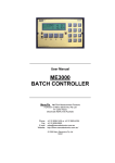
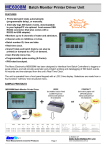
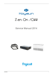
ME3000-RPFS WATER BATCHING SYSTEM Congratulations on choosing a ManuFlo ® (Manu Electronics) preset batch control system. You will now join many thousands of satisfied customers worldwide. Your system comprises: Information sheets included: 1. ME3000 preset Batch Controller specification and options. 2. Installation Guide (plumbing/commissioning). 3. Basic electrical wiring guide. 4. Flowmeter brochure spec (chosen flowmeter normally RPFS) 5. (if ordered) PLC/computer interface spec brochure 6. ME3000 complete user manual Prior to installation: A. Consider a good viewing AND operating position for the ME3000 Batch Controller. B. Remove the detachable 10-pin plug from the rear of the ManuFlo controller. Wire the 240VAC supply. Wire the Active/contact drive, Neutral and Earth from the solenoid valve or return from the external contactor if driving a pump. If starting a pump, make sure the contactor is of sufficient amperage rating to handle the pump current draw. See wiring diagram. C. Install the flowmeter as per the installation guide found on the flowmeter brochure. D. Use shielded cable only for connection between flowmeter and Batch Controller. E. The ME3000 Batch Controllers, when used with flowmeters, have internal preset calibration factory calibrated with water. When using other varying viscosity liquids with some flowmeters, a calibration test will need to be performed, and the K-factor re-programmed to the corresponding result. A calibration check must be performed prior to continuous use and commissioning of the system (see installation guide). Recalibration may be necessary for flowmeters other than MES20. See page 13 of the manual. If unsure on any aspect of installation or operation, call ManuFlo or your local installer. Happy batching !!!!!!!!!!!!! ManuFlo Flow Measurement & Control Products Page 1 a division of MANU ELECTRONICS PTY LTD www.manuelectronics.com.au ME3000 MICROPROCESSOR PRESET BATCH CONTROLLER FEATURES Programmable - counts in ml, Litres, KL, ML. keypad input for batch setting, and configuration. 2 line x 16 character display for quantity set and dispensed. 3 indicator LEDs. IP64 front face. Alarm messages shown on LCD display. Safety features include missing pulse detection. Functions include Preact and preset maximum limit. Internal downloadable Event Log. Single channel, can be used with any size flowmeter. Optional PLC/Computer control interface. Optional RS232 printer interface for batch tickets. The ME3000 microprocessor-based preset Batch Controller can be used with pulse output flowmeters of any size, for preset liquid batch control applications. Batch counting can be in units of millilitres, Litres, KiloLitres or MegaLitres. The Controller is fully programmable, and has a range of safety features e.g. if no pulses arrive within a configurable batch start period, or if pulses are interrupted during the batch cycle or if the flow rate falls below the allowed minimum, then the pump voltage contact drive is automatically shut off and an alarm is raised. RUN LED indicates voltage contact output drive when pump or solenoid is activated. FLOW LED monitors and indicates incoming pulses from field flowmeter. OUTPUT LED indicates scaled pulses output from Batch Controller e.g. to a PLC/Computer. Internal audible ALARM sounds momentarily upon completion of batch cycle, and continuously if an error occurs. With the ME3000 Batch Controller using the same instrument housing, and the same 10-pin Weidmuller receptacle plug, as other ManuFlo Batch Controller models, changeover or upgrade is instant with no rewiring necessary. It can be easily interfaced with PLCs (through the optional computer control interface), thus incorporating the controller's safety features and providing a backup batch facility. An optional RS232 interface allows the printing of batch tickets through an associated printer, and the downloading of the internal event log to a laptop/PC for analysis. The controller operates from standard 220 - 250 vac (or optional 110 vac or 12 - 24 VDC) voltage supplies. Contact output drive is via a relay (optional open contact). Standard controllers are in panel mount form, or optionally can be housed in a metal box or IP65 ABS wall mount enclosure. Displays Quantity set/dispensed Flowrate Backflow amount Grand Total (resetable) Batch Id (resetable) Alarms No pulses from flowmeter Batch Limit exceeded Max Flow Limit exceeded Pulse Output Rate exceeded Backflow Overbatch Configuration Calibration i/p pulse scaling Output pulse scaling Pulse output rate limit Batch limit Backflow threshold Min/Max flow limits Batch Units Start/stop delay 4-20mA current output Preact Time and date Date last calibrated Features Event log (upto 300 batches) Indicator LEDs - Run/Flow/Output Optional Outputs scaled Open Collector pulse output e.g. to PLC/Computer 4-20mA output representing flowrate Optional Interfaces PLC/Computer control (stop/start/reset) RS232 printer interface for batch tickets and event log download. The ME3000 controller is designed for compatibility with ManuFlo flowmeters and many other types. N 15022 ManuFlo Flow Measurement & Control Products Page 1 a division of MANU ELECTRONICS PTY LTD www.manuelectronics.com.au OPERATING INSTRUCTIONS ME3000 Switch the power ON to unit. In a few seconds, the display shows SET and RDY(ready), with a zero quantity for RDY, all LED indicators and alarms are off. The unit is ready for batching or configuration. BATCHING: When SET/RDY is displayed, entering a batch quantity via the numeric keypad buttons will cause the displayed SET value to change and flash. Then, pressing the SET button locks in the new value, or pressing CANCEL reverts the value to its original setting, and the display digits stop flashing. Press the START BATCH button to start batch batching the set quantity. The RDY line title changes to REC (received). The voltage contact drive activates, the RUN LED illuminates indicating pump or solenoid are energized, followed by FLOW LED illuminating, indicating pulsing and operation of flowmeter. The digits on the REC (received) display line begin counting upward towards the selected batch quantity. Upon REC digits reaching the selected batch quantity the alarm sounds (short beep) indicating completion of batch; RUN, FLOW and OUTPUT LEDs turn off. The displayed SET and REC values should correspond. If REC digits overshoot target, then scale back the difference by changing the Preact value via the Configuration Mode (see below). To interrupt batch, push STOP button; REC counting will stop, and drive contact goes off. Push START BATCH to resume batch. On batch completion or termination, press RESET. Display REC line title changes to RDY (ready). To dispense the same set quantity again, press START BATCH. Otherwise, use the keypad to enter a new batch quantity. Warning: if RUN or FLOW LED indicators are on, but controller is not counting, discontinue use and call for service. EVENT LOG: using a straight-through female- to-female DB9 cable, connect from the Batch Controller’s (optional) RS232 port to a Laptop/PC serial port. On the Laptop, start the HyperTerminal software (supplied as part of Windows), set up a connection at 9600 baud, 8 Data Bits, no parity, 1 stop bit, and capture text to a file. On the Controller, press the CANCEL and RESET buttons (those marked with ‘#’) simultaneously for 5 secs, and the Event Log will download. To stop download, press CANCEL for 2 secs. CONFIGURATION: The Controller is factory configured to your requirements, but can be re-programmed by the user if required. Configuration Mode is entered from the SET/RDY display by pressing the CANCEL and STOP buttons (those marked with a ‘*’) simultaneously for 5 seconds. Use the buttons with the up/down arrows to step through configuration settings. When a configuration value is diplayed, entering a new value via the keypad causes the display value to change and flash. Then, pressing SET locks in the new value, or pressing CANCEL reverts value to its original setting, and the display digits stop flashing. Use the up/down arrows buttons to step through more configuration settings, or press CANCEL for 2 seconds to exit to the SET/RDY display. CALIBRATION 1) The Batch Controller is set up for the connected flowmeter using the Calibration Input pulse scaling item under Configuration Mode, to match the flowmeter’s output pulse value. On-site calibration adjustment and test: 2) Must adjust what is shown as received (REC) on the Batch Controller LCD display to match a known amount dispensed. So, set batch quantity to say 190L, and batch into a 200 litre (44 gallon) drum. 3) If the amount collected is more than the REC amount shown on the LCD display, then decrease the Calibration Input value by the same % difference e.g. if collected 200L when 190L on LCD, this is 10L more or 5% over (10/190x100%). So, decrease the calibration value by 5% i.e. if Calibration Input value is 300, new value is 300-5% = 300-15 = 285. 4) If the amount collected is less than the REC amount shown on the LCD display, then increase the Calibration Input value by the same % difference. e.g. if collected 180L when 190L on LCD, this is 10L less or 5% under (10/190x100%). So, increase the calibration value by 5% i.e. if Calibration Input value is 300, new value is 300+5% = 300+15 = 315. 5) PREACT: To calibrate inflight overflow, enter Configuration Mode (as described above), and set the Preact value to the same overflow reading as indicated by the LCD display, where overflow = (the REC quantity) - (the SET quantity). Example: You set 190 Litres, batch the quantity, 200 Litres is shown on display, and 200 Litres is collected in drum. A valve may take extra time to close, so the received quantity usually overshoots. So, set 10 Litres on Preact to deduct the 10 Litres overshoot. Next batch, the set batch quantity, LCD REC reading and amount collected in drum are all 190 Litres. SPECIFICATIONS Power supply Fuse Frequency input Event Log Output to flowmeter Relay Display Connection Batch entry Optional Outputs Optional interfaces Instrument housing Mounting External dimensions Weight 220-250 vac (optional 110 vac or 12-24 VDC) 1 Amp (5 x 20mm case) 5 KHz internally records up to 300 batches 12 VDC upto 100mA Max. 240 vac, 1 A. Open Contact on request. 2 line x 16 character, for quantity set and dispensed. 10 pin Weidmuller mating plug and socket quantity selection and commands via IP64 keypad scaled pulse output; 4-20mA output RS232; PLC/Computer stop/start/reset ABS hi-impact case mould Panel mount. Panel cutout :190 L, 122 H mm 206 L, 130 H, 90 D mm. 1 kg shown with optional -SC and -5P interfaces Due to continuous product improvement, specifications are subject to change without notice. ManuFlo Flow Measurement & Control Products Page 2 a division of MANU ELECTRONICS PTY LTD www.manuelectronics.com.au ME3000 Batch Ticket Event Log example ORDER CODES ME3000 Batch Controller, 240vac. Options: Code -110 -OC -L -SC -MC Description 110 vac powered Open Contact output Code -DC -OP For connection to a coil-type flowmeter. RS232 Serial interface -SSR 4-pin PLC/Computer Command (Start/Stop/Reset) interface plug -MC2 -5P Description 12-24 VDC powered Alarm output, Batch complete output, and 4 - 20 mA output. External command: Start/Stop/Reset, for connection to HB2500-SSR housing box. 5-pin computer interface plug (start, stop, reset, pulse, +12V) for Jonel, Eagle etc PLCs. 2-pin plug for scaled open collector pulse output. Includes 4-pin external command (Start/Stop/Reset) interface plug. e.g. “ME3000” is the standard Batch Controller, 240vac powered, without any of the options, whereas “ME3000-MC2” is an ME3000 Batch Controller with a scaled open collector pulse o/p, and external Start/Stop/Reset. ACCESSORIES Code APM-n93XS TMP Description Thermal Ticket Printer. with power supply. suitable for custody transfer dockets for ME3000-SC. ME3000-SC and APM-n93XS printer, wired and mounted in a key lockable rugged IP64 hinged enclosure. automatic ticketing. prints Batch ID, quantity, time and date. ribbon and paper easily changed. Ideal for delivery trucks or loading and discharge locations where a custody transfer docket is required. ManuFlo Flow Measurement & Control Products Page3 a division of MANU ELECTRONICS PTY LTD www.manuelectronics.com.au RPFS - ROTA PULSE FLOW SENSOR (Insertion Paddlewheel) FEATURES +/- 2.5% accuracy @ velocity range 0.5 to 8.5 m/sec. +/- 1% over linear range 0.7 to 7.0 m/sec. Repeatability of rate +/- 0.6%. NPN inductive pulse with internal amplification. Square wave output with short circuit protection. Inductive coil pulse option. 50C or 120C temperature models. Simple installation and maintenance. Large range of pipe adapter fittings in sizes 15 to 150mm. New lighter-weight rotor design for improved response at lower flowrates (from 0.25 m/sec for RPFS-P model). Marine-grade alloy rotor without magnets. Australian made since 1984. DESCRIPTION The Rota Pulse Flow Sensor (RPFS) paddlewheel insertion type flowmeter uses a proven principle of flow measurement, which is used worldwide. The RPFS comes in three model variants: RPFS-P for liquids up to 50C (plug-in cable) RPFS-H for liquids up to 120C RPFS-L for liquids up to 120C (special low current inductive pulse) RPFS-P All three models insert directly into a large range of pipe adapter fittings available in PVC, Galvanized Iron, Brass, Stainless Steel or Polypipe materials, covering pipe sizes 15 to 150mm (standard sizes). This makes the RPFS suitable for a wide range of liquid flow measurement, monitoring and batching applications. With only one moving part and limited intrusion into the pipe, and combined with its flow-through design, the RPFS allows accurate measurement of liquid flows with virtually no headloss. Each of the 4 blades of the rotor (paddlewheel) extends approximately one centimeter into the flowing liquid. The sensor generates a square wave pulse with the frequency output proportional to flow velocity and proportional to pipe diameter. The RPFS incorporates internal amplification, allowing pulse transmission up to 1000 metres to the receiver device. The RPFS-P’s specially constructed metal shielding jacket makes that unit immune to electrical interference. Magnets are not used in the RPFS models, thereby eliminating iron particles jamming the rotor. The alloy rotor used also makes the RPFS less susceptible to interference from turbulence and particles hitting the rotor, thereby giving superior flow results. SPECIFICATIONS Supply Voltage Output signal Cable length Fluid Temperature Weather rating Pressure rating Accuracy Pipe Sizes RPFS-P 5-30VDC NPN open collector 50% duty cycle pulse Model RPFS-H 5-30VDC NPN open collector 50% duty cycle pulse RPFS-L Inductive coil 260ohms. Inductive sine wave pulse 50% duty cycle pulse 0.1v to 2v p/p generated 3 metres, plug-in cable 2 metres cable 2 metres cable 3-core (3 wire) 2-core shielded (3 wire) 2-core shielded (3 wire) 50 C. max. 120 C max. 120 C max. IP68 IP65 IP65 200psi 400psi 150psi 1% linearity 0.7 to 7.0 m/s, 2.5% for 0.5 to 8.5 m/s, Repeatability +/-0.6% 15 to 150mm standard, larger pipes via BSPB special adaptor. ManuFlo Flow Measurement & Control Products Page 1 a division of MANU ELECTRONICS PTY LTD www.manuelectronics.com.au INSTALLATION GUIDE Adapter tee keyway fittings are available in: 1. PVC Class 18 Cat. 19 (glue-ends) pressure pipe sizes 20, 25, 32, 40, 50, 65, 80 & 100 mm. PVC high pressure saddleclamps: 50, 80, 100 & 150 mm. 2. Galvanized iron Bsp(f) threaded connections in pipe sizes 25, 32, 40 & 50 mm. 3. Copper/Brass Bsp(m) threaded connection end process pipe tube tees 15 & 20 mm. 4. Polypipe saddleclamps in pipe sizes 50, 63, 75, 90 & 110 mm. PVC saddles 80, 100 & 150mm. For tapping into existing or larger pipe works: Use BSPB brass or BSPSS Stainless Steel pipe adapter keyway nipple - c/w locknut, has 1” OD Bsp thread for screwed insertion into 1”(f) half-sockets. BSP adapters can be welded directly to pipe (see Fig. 1). Installation Conditions A minimum of 10 x pipe diameter before the sensor and 5 x pipe diameter after sensor of straight pipe section must be fitted, with no reductions, enlargements, restrictions, valves etc within this section. This will ensure optimum accuracy performance and help eliminate turbulence. The RPFS sensor must measure in a full pipe flow section. Can be installed in a horizontal, inclined or vertical pipe position. (Note: If mounted in horizontal or inclined pipe, make sure insertion position of sensor is at top or 45 from top, not on the underside). ELECTRICAL INSTALLATION/DATA Selection of pipe diameter For best operating results use the table below: Pipe size (mm) Flowrange (Litres/min) Min Max 15 20 25 32 40 50 65 80 100 150 6 10 15 25 40 60 100 155 240 535 84 150 235 385 600 940 1590 2410 3760 8480 Cable connection Pulses/Litre (approx.) * RPFS-P# Black = Pulse Brown = + 5-30 VDC Blue = O.V. ground/shield 207 116 75 46 30 20 12 7 .3 4 .6 2 .1 RPFS-H# White = Pulse Red = + 5-30 VDC Shield = O.V. ground/shield RPFS-L # If connecting to non-ManuFlo equipment, a 2K2 pullup resistor may be required between (+) and Pulse. For >150mm diameter pipes: Pulses per Litre = 46512/(Pipe diameter in mm)2 * NOTE: Due to gravitational forces, the pulse output value can differ up to 6% between a vertical flow that is upwards or downwards. Where possible, perform a calbration check to determine pulserate given the pipe diameter and flow conditions. Once calibrated, meter will give linear and repeatable results within the flowrange. ManuFlo Flow Measurement & Control Products White = Signal Red = Signal Shield = connect to signal/ground Page 2 For extra cable length, use shielded cable only! WARNING: To avoid electrical interference the RPFS-H and RPFS-L should not be installed within 30cm of any AC fields, otherwise 50Hz could be detected and create oscillations. a division of MANU ELECTRONICS PTY LTD www.manuelectronics.com.au Sensor Construction Model Body O-rings x2 Rotor Bushes Axle Lockcap Dimmensions Overall (approx.) RPFS-P Delron (Acetal) Neoprene Delron PVDF 130L x 30W RPFS-H Brass Viton Marine grade alloy Delron Tungsten Carbide Brass 150L x 30W RPFS-L Delron Neoprene Delron PVDF 135L x 30W MAINTENANCE With clean liquids, a check is required once every year. In applications with reclaimed or contaminated fluids, regular monthly (at worst quarterly) maintenance checks are recommended. To remove the sensor, first unscrew the PVC locking cap. Remove the sensor by pulling up, do not twist until clearing keyway. Do not pull by cable. If the paddlewheel (rotor) is dirty, then clean with diluted hydrochloric acid. For ease of removal or refitting, lubricate the body O-rings. If the paddlewheel requires servicing, push out the axle, remove the wheel, and service or replace the bushes as required. RPFS-H APPLICATIONS Since the RPFS Flow Sensor was first manufactured in 1984, over 8000 units are now in use worldwide. They are used in a large variety of applications, including measurement of fresh and recycled water in concrete batch plants, measurement of petrol/diesel, water irrigation, salt water, chlorinated water and countless other low viscosity liquid measurement processes (Note: is not suitable for pulsating flows). RPFS-P and RPFS-H sensors can be connected direct to PLCs, ManuFlo ME995 preset batch controllers or FRT303 Flowrate/Totalisers, or just about any other process controller/indicator device (up to 1000m away). The ManuFlo UIC universal pulse scaler card allows conversion of the output pulse to individual requirements – ideal for PLC inputs of DC NPN/PNP or AC triac types. Pulses can be scaled down or factored to a desired engineering unit, to cater for slow counting PLCs. The RPFS-L inductive coil sensors are energy misers suitable for low current requirements and are ideal for battery powered applications using FRT303 or ME5 Indicators (up to 150m away). RPFS-type flow sensors are designed to operate with ManuFlo equipment (our equipment has internal pull-up resistors at the inputs). If using an RPFS with non-ManuFlo equipment and pulses are not being detected, then fit a resistor of value 1.5K - 3.3K across the Pulse and (+) positive input to act as pull-up resistor (the exact resistor value should be determined by the current draw to suit your equipment). ORDERING CODES Item RPFS-P RPFS-H RPFS-L Description NPN transistor 5-25VDC sinking pulse, liquid temperature to 50C. NPN transistor 5-25VDC sinking pulse, liquid temperature to 120C. Inductive coil pulse signal for amplified inputs, liquid temperature to 120C. NOTE: All RPFS sensors are supplied with a screw-down locking cap. (See page 4 Fig. 2, for pipe installation adapter fittings) ManuFlo Flow Measurement & Control Products Page 3 a division of MANU ELECTRONICS PTY LTD www.manuelectronics.com.au RPFS - PIPE ADAPTER FITTINGS Material PVC with PVC Keyway SPARE PARTS Size mm 20 25 32 40 50 65 80 100 80 100 150 Order Code PVC20 PVC25 PVC32 PVC40 PVC50 PVC65 PVC80 PVC100 PVC80SC PVC100SC PVC150SC All Brass All Stainless 25 32 40 50 20 25 GAL25 GAL32 GAL40 GAL50 GAL20 SS25 As above but all brass. As above but all Stainless 316. COPPER c/w brass keyway 13 17 CP15 CP20 Copper tube, brass Bsp(m) thread end connections POLY with brass Keyway 50 63 75 90 110 SC50 SC63 SC75 SC90 SC110 Saddle-clamped on black poly irrigation pipes, to fit, a 1" hole must be drilled into pipe. 25-250 25-250 BSPB BSPSS Brass adaptor with Keyway for existing metal,copper or stainless steel pipe runs. PVC Saddle-clamp GALVANIZED with brass Keyway BRASS STAINLESS Keyway PVC fittings Adapter Type Class18, Cat.19, glue-in (f) socket connections for PVC pipe sections. Saddleclamps to 1500Kpa to suit PVC pipe sections Order Code BHS BLN BS020 BS020V LC PW-N PWAH PWRB PC STC Description Brass Half Socket 25mm Brass Lock Nut Neoprene O-ring Viton O-ring Locking Cap Paddlewheel, c/w bushes Axle for paddlewheel Bushes, for paddlewheel Plug-in cable for RPFS-P Sealer locking cap Threaded Bsp(f) entries for galvanised metal, copper or other pipe materials. GAL fittings Various pipe adapter fittings Fig. 2 Due to continuous product improvement, specifications are subject to change without notice. ManuFlo a division of 41 Carter Road, Brookvale Sydney NSW 2100 Australia Flow Measurement & Control products Rev. 0511/1 MANU ELECTRONICS PTY LTD Page 4 Ph: + 61 2 9905-4324 or 9938-1425 Fax: + 61 2 9938-5852 Email: [email protected] Web : www.manuelectronics.com.au RPFS and ME995 Wiring and Plumbing Diagrams (c) 2004 Manu Electronics Pty Ltd 1 RPFS and ME995 Wiring and Plumbing Diagrams (c) 2004 Manu Electronics Pty Ltd 2 RPFS and ME995 Wiring and Plumbing Diagrams (c) 2004 Manu Electronics Pty Ltd 3 RPFS and ME995 Wiring and Plumbing Diagrams ManuFlo ®TM TROUBLE SHOOTING GUIDE FOR BATCH CONTROLLER / ROTA PULSE FLOW METER SYSTEMS PROBLEM POSSIBLE CAUSE SUGGESTED SOLUTION No power to batch controller or displays not on Blown fuse or holder not tightened +12vdc and O.V. shorted No main power supply Check fuse, tighten fuse holder (at rear of controller) Check pulse cable from DCD to RPFS meter Check power supply, check wiring Pulse fails at start of batch (1.5 seconds after typical) •Check calibration (K-factor) setting •000 calibration -pulsefails. Make sure a calibration value is set. Seized paddlewheel Remove RPFS, inspect; clean with acid, check axle/bushes make sure paddlewheel spins freely Check and service solenoid valve, check output control voltage is 240vac(N & C, pins 7&9) when pushing start button Restrictionor service gate valve closed Open gate valve Empty water tank Check water level Pump not turning Check and service pump •Pump foot valve failed •Empty pipe, Install non-return valve Signal cable cut, bad joint at JB, Check signal cable for 12VDC at junction box near RPFS meter oxidised cable- leakage If no power, cable cut or oxidised- repair/replace. Unwire RPFS, take upto batchroom, remove extension cable and hardwire RPFS direct into the Batch controller (P,+,-), spin wheel should count on display, if so, then extension cable or connections at JB faulty, if no counts & 12vdc present then RPFS faulty •RPFS not positioned in pipe •Check RPFS slots are in keyway position, lock cap secured Paddlewheel not inserted into flow stream RPFS Flowmeter faulty Replace with new RPFS Solenoid valve not opening Pulse fails during batch cycle program. Flowrate too slow Pipe buildup restricting flow Paddlewheel problem Open restriction gate valve, or increase minimum flowrate in Pipe diameter too big for flowrate (reduce pipe dia. or increase flow) Cleanout pipelines, calcium buildup on pipewalls -recycle systems Calcuim buildup on wheel, soak in diluted acid. Warn bushes. Backflow alarm after batch complete Non return valve faulty (jammed open) Clean, service or replace •Solenoid valve not properly closed •damaged seal, faulty solenoid Batch target display counter counts past batch selection Flowrate too fast excessive overflow •Intermittant overflow past batch select •Faulty solenoid valve not closing or water does not stop Overbatch alarm sounds Turn down gate valve to restrict flowrate or set preact (overflow deduct) function to compensate Reduce delivery pipe diameter •service solenoid valve, check air pressure properly, insufficent air pressure Wet loads, more water collected than indicated Dry loads, less water collected than indicated Paddlewheel bushes worn Wheel dirty, flowing overrange Requires recalibration test Check paddlewheel Replace with new paddlewheel, recalibrate Set new calibration figure. Controller starts counting when power switched on Active and contact power drive short circuited Contactor fused due to excessive current draw from pump Relay fused due to excessive current draw on solenoid coil - install higher current rated contactor or install contactor Interferance on pulse cable input –use shielded cable only. ANY OTHER PROBLEMS REFER TO ME3000 USER MANUAL –Trouble shooting guide. Sequential fault finding and rectification 1. If a another ManuFlo controller (any model) is available, simply unplug doubtful unit and plug in exchange unit. If the new unit is also not operating correctly, then the problem is isolated to the pulse flowmeter or wiring. 2. When checking flowmeter, reset the ManuFlo controller. Remove the flow sensor and spin the paddlewheel. Check that the ManuFlo controller has registered a number of counts on its display. If so, the electrical connections are probably OK. If no counts are registered, check that 12VDC is supplied to the flow sensor. If supplied, then switch off the ManuFlo controller and replace the RPFS flow sensor. 3. The flow sensor paddlewheel is jammed, damaged etc. (For servicing, refer to the flow sensor brochure). If in further doubt, contact your local representative, or ManuFlo on ph +61 2 9938 1425 or 9905 432 ManuFlo a division of MANU ELECTRONICS PTY LTD Flow Measurement & Control Products www.manuelectronics.com.au