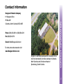
1
Remote Sportcaddies for the Serious Golf Athlete
Made in USA
Model:
Serial#:
Important!
Visit www.KangarooOwner.com/warrantycardform.html
within 30 days of purchase to register your warranty.
Thank you!
Dear
I am sure you are looking forward to many enjoyable rounds on the golf course with your new X-Series. To make absolutely sure
you do, a team of us carefully put together this easy to use Owner’s Manual which includes operating and maintenance instructions,
Before your X-Series was shipped, it was given a special pre-delivery inspection and operational test, all parts being checked
and aligned to ensure it is ready for the golf course. However, if you discover something faulty or have questions, don’t hesitate to
give me a call.
On behalf of the entire Team at Kangaroo Products Company, THANK YOU VERY MUCH!
Thank You
warranty information, and helpful tips on how to keep your X-Series looking new and running smoothly.
Sincerely,
P.S. Enclosed is my business card. Feel welcome to pass it along to a fellow golfer who may be interested
in purchasing an X-Series.
2
Hillcrest ABX
Hillcrest MAX
Table of Contents
Reporting Damage During Shipping ........................................................................................5
Contact Information .................................................................................................................6
Assembly ..................................................................................................................................9
Power Controls & Operation ..................................................................................................17
Remote Guidance System .....................................................................................................23
AutoBrake ...............................................................................................................................33
Free-Wheeling Mode ..............................................................................................................35
Rear Wheel Assembly and Removal .....................................................................................37
Battery & Charger....................................................................................................................39
Optional Equipment ...............................................................................................................43
Technical Specifications ........................................................................................................47
Maintenance ...........................................................................................................................49
Table of Contents
Visit Kangaroo...........................................................................................................................7
Warranty ..................................................................................................................................51
Troubleshooting ......................................................................................................................57
Notes .......................................................................................................................................63
4
Damage During Shipping
What to do if a Kangaroo product
or part is damaged during shipping
Please call or e-mail Kangaroo (see Contact Information on page 6) with your invoice number and customer number.
Specify which product or part is damaged. Do not return the damaged products or parts back to Kangaroo; we will
contact the shipping carrier to file a claim. Kangaroo will send replacements. The shipping carrier is responsible for
picking up the damaged merchandise, if they choose to, and sending the item back to Kangaroo.
Do not dispose / destroy any carton or packing material in which merchandise was shipped. The carrier may
contact you for an inspection visit or send a pickup for the merchandise.
Contact Information
Kangaroo Products Company
PO Box 607
Columbus, North Carolina 28722-0607
Phone: (800) 438-3011 or (828) 894-8241
Fax: (828) 894-2718
E-mail: [email protected]
To order parts and accessories visit:
www.KangarooOwner.com
Kangaroo’s worldwide headquarters is located just one
mile from interstate 26, 40 miles southeast of Asheville,
North Carolina’ and 30 miles northeast of
Spartanburg, South Carolina.
COntact Information
111 Kangaroo Drive
6
To Asheville
US Hwy 74
Exit 163
Kangaroo Products
111 Kangaroo Drive
TM
Exit 67
NC Hwy.108
to Mill Spring
and
Rutherfordton
To Tryon
Exit 67
NC
Welcome Center
NC
SC
To Spartanburg
Visit Kangaroo
Follow Interstate 26 east toward Spartanburg, South Carolina. Take exit 67 (US-74) toward Rutherfordton. Follow
US-74 approximately one mile to exit 163 then turn RIGHT toward Columbus. Kangaroo will be 1/2 mile
on the RIGHT.
From Charlotte and Gastonia, North Carolina via Interstate 85 and US-74.
Follow Interstate 85 south toward Spartanburg, South Carolina. Take exit 10B (US-74) toward Kings Mountain and
Shelby. Follow US-74 approximately 69 miles to exit 163. At exit 163 turn LEFT toward Columbus. Kangaroo will be
1/2 mile on the RIGHT.
From Columbia, and Spartanburg, South Carolina via Interstate 26.
Follow Interstate 26 west toward Asheville, North Carolina. After entering North Carolina take exit 67 (North Carolina
Highway 108) and follow the signs to Columbus. Kangaroo will be 1.1 miles on the LEFT.
From Atlanta, Georgia via Interstate 85
Follow Interstate 85 north toward Greenville, South Carolina. Take exit 70A (Interstate 26) toward Asheville, North
Directions to Kangaroo
From Asheville, North Carolina via Interstate 26.
Carolina. After entering North Carolina take exit 67 (North Carolina Highway 108) and follow the signs to Columbus.
Kangaroo will be 1.1 miles on the LEFT.
8
B
C
A
Assembly
Components:
A- Chassis
C- Upper Caddie Structure
Assembly
B- Electronic Front Drive
10
Figure
Figure
1
2
Assembling your X-Series Motorcaddie
Your Kangaroo X-Series Motorcaddie is shipped without the rear wheels attached. See pages 37 and 38 for rear
wheel assembly and removal instructions.
1.Steady the Chassis by using the hand-hold, located in the bottom of the battery tray. Insert the Electronic
Front Drive into the hole located in front of the battery tray, and close the draw latch. (Figure 1)
Note: The Upper Caddie Structure and Electronic Front Drive will fit in either hole—therefore be sure the
2.Insert the Upper Caddie Structure into the top of the Chassis just behind the battery tray, and close
the draw latch. (Figure 2)
3.Fold down the Flex-Adjust Bag Support (Figure 7 on page 15) until it comes to a stop.
4.Remove the three plastic tie-wrap bands from the handle. Simply press down on each of the red tabs on the
tie-wraps that are encircling the handle grips. While pressing down on the red tab, push the extended edge
Assembly
motor is on the top right side, while standing behind the X-Series.
back through the locking mechanism to loosen the hold on the handle grip.
Note: Make sure the Function Switch is in the “OFF” position. Begin to establish the habit of putting the
switch in the “OFF” position while assembling your Kangaroo X-Series.
Cont:
12
Figure
3
Figure
Figure
4
5
5.Connect the plug from the Upper Caddie Structure to the receptacle in the Chassis. (Figure 3)
Note: Always handle the plug when connecting or disconnecting the control cable. Pulling on the wire
can cause damage.
6.Connect the Electronic Front Drive by inserting the black plug into the receptacle on the lower left of the
Remote Receiver. Push inward on the lock ring while twisting it clockwise until it stops. (Figure 4)
the terminals to the back of battery tray. (Figure 5)
a. Connect the red clip to the (+) positive terminal.
b. Connect the black clip to the (-) negative terminal.
Note: If the cables are accidentally reversed, your X-Series will not run until the polarity is corrected.
(Your X-Series is equipped with reverse-polarity protection, and connecting the terminals backwards
Assembly
7.Remove the black plastic cover (not shown) from the battery terminal. Set the battery into the battery tray with
will not harm you or the unit.)
Adjustments
Your X-Series comes with an assortment of Allen-type wrenches. They are provided for adjustments, keeping
screws tight, and for adding optional equipment.
14
Figure
Figure
6
7
Draw latch:
If the Upper Caddie Structure or Electronic Front Drive is loose, turn the draw latch metal adjustment ring clockwise
to tighten. Do not over-tighten the adjustment ring as this may cause the draw latch to break when engaged. If the
draw latch will not lock in place, loosen the draw latch by turning the metal adjustment ring counter-clockwise.
(Figure 6)
Note: The metal adjustment ring may be difficult to turn. A standard pair of needle nose pliers can be used
Flex-Adjust Bag Support:
The Flex-Adjust Bag Support on the Upper Caddie Structure(Figure 7), also referred to as the yoke, is designed to
fold up for easy transportation and storage. It can be adjusted to grip your golf bag by bending the arms open or
closed as needed.
The Flex-Adjust Bag Support is attached to the stainless steel tubing at the best position to hold most golf bags
Assembly
to make adjustments. To avoid possible breakage, always close draw latches before placing Chassis into your car.
securely. If you have an unusual bag, or a personal preference for its position, its clamp can be moved up or down
the tubing to any point you like. The Bag Support is secured with four 5/32” Allen-type machine screws and a
suitable wrench is provided with your X-Series. Simply loosen the four screws and adjust the clamps accordingly,
then re-tighten securely.
16
Figure
Figure
8
9
Accelerator
Speed is controlled by the Accelerator located between the handle grips. The decal indicates speed in relation to
the Accelerator position. (Figure 8)
Note: Turning the Accelerator all the way down does not turn off Power Controls, even if your X-Series is not moving.
There is a feature, known in technical terms as “ramp up”, that automatically provides a gentle start at any setting
up to, and including, full speed. Even so, your X-Series is very powerful, and it is best to start out at lower speeds.
Function Switch
The Function Switch is located on the top center of the handle. (Figure 9)
• Switch to the MANUAL mode when remote control is not desired.
• Switch to REMOTE mode when you are ready to resume play with Remote Guidance.
Controls and Operations
Power Controls and Operation
18
Figure
10
Normal Operation:
1.Prior to beginning play, rotate the Accelerator to the SET position (Figure 8 on page 17). You can vary the
2.Position the Function Switch to ON (Figure 9 on page 17).
3.Position the Function Switch to the MANUAL position when Remote Guidance is not desired.
Manual Mode is recommended when using your X-Series in parking lots, in tight spots, and around
water hazards.
4.Position the Function Switch to the REMOTE position when you are ready to begin play
with Remote Guidance.
5.Press the GO button on the Remote Transmitter. Your X-Series will start and ramp up to your preset speed.
Press GO a second time and your X-series will increase its speed, automatically ramping up to 90% of its
maximum speed (approximately 4.5 mph). Press GO a third time and your X-Series will automatically decrease
to your original preset speed. If you press GO a fourth time, your X-Series will again increase to 90% of its
maximum speed. Each activation of GO while your X-Series is moving will alternate between your preset
speed and 90% maximum speed. (Figure 10)
Cont:
Controls and Operations
Accelerator to suit your own walking pace after you begin play.
20
Figure
11
6.To stop your X-Series, press STOP on the Remote Transmitter. To achieve maximum braking the
Function Switch must be turned OFF. There is no need to change the accelerator when stopping
Reminder: The arrows on the Remote Transmitter indicate steering direction as if you were operating your
X-Series manually. If your X-Series is coming toward you, the steering direction of the arrows are reversed.
7.If you stop your X-Series on a hill, always turn it across the slope to park it. The X-Series models do not have a
parking brake and will creep down a hill on their own.
Runaway and Circuitry Protection
Your X-Series will automatically shut itself off if the Function switch is left in Remote or Manual position for an
extended period of time. The reason for this is to prevent a possible runaway situation. This also allows the solid
state circuitry a cool-down period. To avoid activation of this safeguard, turn the Function switch OFF each time you
stop. Merely turning the speed all the way down will not reset this internal timer and will cause your X-Series to
unexpectedly shut off. If you forget, and your X-Series unexpectedly “cuts out” or is “dead”, turn the Function Switch
to OFF and then back ON to restart your X-Series.
Controls and Operations
and re-starting. (Figure 11)
22
Figure
12
Figure
Figure
13
14
Remote Guidance System
(Figure 13), and Electronic Front Drive (Figure 14). Remote Guidance System operates on an FM Pulse Code
Transmittal System that is FCC approved, and requires no operator’s license. Remote Guidance System is relatively
low power (milliamps) and is subject to little outside interference.
Remote Transmitter and Remote Receiver devices comply with Part 15 of FCC rules. Operation of these devices is
subject to the following two conditions: (1) The devices may not cause harmful interference, and (2) The devices
must accept any interference received, including interference that may cause unintended operation.
The antenna is permanently mounted inside the Remote Receiver to make it more water resistant. You should not
attempt to open the Remote Receiver - doing so will break the seal and void the warranty.
Activating Remote Guidance System
See Power Controls & Operations on page 18.
Remote Guidance System
Remote Guidance System consists of three components – the Remote Transmitter (Figure 12), Remote Receiver
24
Figure
15
Centering the Steerable Front Wheel
Before you begin play the front wheel must be centered, so your X-Series will track straight. Use the centering knob
wheel by hand. The front wheel must be centered electronically by turning the black knob. The knob is very
sensitive. Rotate it slowly to adjust the front wheel right or left as needed. When the front wheel is centered, the
knob can be turned slightly right or left without the wheel moving. If the wheel is not centered, any turn of the knob
will cause the wheel to swivel.
Automatic Self-Centering Front Wheel
Remote Guidance System’s built-in centering control will automatically center the front wheel every time you stop
transmitting a directional signal with the Remote Transmitter. The centering function will not work properly unless
you center the front wheel using the electronic centering knob (as described above).
During normal operation, a sensor in the Remote Guidance System detects course conditions and allows for small
terrain deviations, thus allowing your X-Series to follow a straight line of travel. If for any reason the front wheel
becomes jammed and cannot return to center, the self-centering feature will shut off after 6 seconds. To dislodge
the obstacle, turn the Function Switch to OFF and remove the obstruction. Turn the power back ON. The wheel
should now automatically align itself. If it does not, re-adjust using the centering knob as shown on this page.
Remote Guidance System
(Figure 15) on the rear of the Remote Receiver to adjust the front wheel. Do not attempt to turn the front
Cont:
26
The centering and directional control in the Electronic Front Drive can be damaged if the unit rams into any obstacle.
When your X-Series must be maneuvered in close areas, it may be best to do so manually; for instance, across
bridges, around trees, or in parking lots. X-Series includes a Bumper Guard to help protect the centering device.
Damage caused by hitting obstacles is not covered under the manufacturer’s warranty. All Remote Guidance System
units must be returned to Kangaroo for proper repair. There are no user serviceable components inside.
Electronics (Remote Receiver and Remote Transmitter)
Remote Receiver
The Remote Receiver is the main control center of the Remote Guidance System. It processes and relays all of the
signals from the Remote Transmitter to the Electronic Front Drive.
Automatic Safety Shut-Off
The Remote Receiver is designed to receive a signal from the Remote Transmitter every 28 to 30 seconds. If for any
reason the unit does not receive a signal within this time span, it will automatically shut off. The auto shut-off will
also stop your X-Series if it gets out of signal range. This is a required safety function to prevent runaway. In normal
use, most golfers will be making many directional adjustment signal transmissions. However, if you do not press any
button on the Remote Transmitter for 30 seconds, your X-series will stop. This is a safety feature, not a defect. If
your X-Series stops, just press the GO button and the X-Series will start again.
Remote Transmitter
The Remote Transmitter is supplied with a fresh, standard Alkaline 9-volt battery. The battery compartment is
the 9-volt battery should last 3 months. Replace the Remote Transmitter battery at least every three months.
Keep Dry
Use great care in operating your X-Series around water. The Remote Transmitter is sealed to be water resistant.
However, if dropped into a puddle, pond, or creek, it may become damaged.
The Remote Receiver should be protected at all times against water damage. If your X-Series runs into a body of
water and the Remote Receiver becomes submerged, the electronic circuit board inside will be destroyed. When
washing the unit, avoid direct water contact with the Remote Receiver. If the Remote Guidance System electronics
are damaged by extreme exposure to water, e.g. submerged in a pond, the damage will not be covered under the
manufacturer’s warranty.
Remote Guidance System
located on the bottom rear of the transmitter. The cover slides off for easy battery replacement. Under normal use,
28
Figure
15
Confirm Command Indicator
1.When a signal is given, the red Confirm Command light (Figure 15) on the Remote Transmitter will flash
command. NOTE: The buttons are easy to press. There is no need for excessive force. When the indicator
light flashes, the signal has been sent.
2.When the 9-volt battery is weak, the light will stay on continuously, indicating the 9-volt battery must be
replaced. Remote Guidance System may have a loss of signal strength and a loss of range when the
Remote Transmitter battery is weak. To test the battery, press and hold any function button. If the light
stays on while the button is depressed, the battery is weak and should be replaced.
The position of the Remote Transmitter is important during signal transmission. In order to achieve maximum range,
hold the Remote Transmitter with the control buttons on top, and the back of the Remote Transmitter toward the
ground. Point the front of the Remote Transmitter toward your X-Series. The Remote Transmitter will operate if held
in other positions, but the overall operating range will be decreased. The range will also be affected if there are
obstacles between you and your X-Series such as trees, buildings, cars, etc.
Play it Safe
Expect an orientation period to learn the controls of the Remote Guidance System. Do not try to learn the controls in
close quarters. Never try to operate your X-Series while it is out of your sight! Play it safe! Your new X-Series is not a
Remote Guidance System
twice – once with the pressing of the button, and again when the button is released, confirming your
toy. Always use common sense while operating.
30
Figure
16
Figure
Figure
17
18
Manual Steering Operation
To operate your X-Series in Manual Mode, Press the Remote Transmitter’s STOP button. Then turn the Function
Padded Case for Remote Transmitter
Included with your new X-Series is an attractive Padded Case screenprinted with Kangaroo logo (Figure 16).
It can be worn two ways:
1.Looped over a belt with the back flap secured by the Velcro®.
2.Slipped over the waistband of pants or a skirt.
Try it both ways, to decide which you prefer! The Padded Case’s long back flap is stiff enough to hold the
Remote Transmitter secure. When you put your Remote Transmitter away, flip the long flap forward,
secure with Velcro®, and store in a safe, dry place.
Remote Transmitter Swivel Clip System & Belt Clip
The Remote Transmitter Swivel Clip System (standard on both MAX and ABX) mounts securely to the
Scorecard Platform (Figure 17). The included Remote Transmitter Belt Clip can also be worn on your belt,
pocket or golf bag. (Figure 18)
Remote Guidance System
switch to MANUAL. Adjust the Accelerator if necessary.
32
Hillcrest ABX
AutoBrake Operation
As your X-Series travels downhill with the power switched ON, turn the Accelerator downward to a slower setting.
Your X-Series will slow down and give you a feeling of security as you travel
down the hill.
If the slope is extremely steep, you may turn the Function Switch OFF, which will provide approximately 50% more
turning the Function switch OFF and ON until you reach the bottom of the hill.
Important: If you must tow your X-Series either forward or backward, always place it into
Free-Wheeling Mode FIRST! Gear damage may result from pulling or pushing your X-Series with great force or for
long distances. Damage incurred from failure to disengage drive wheels from gear train is NOT covered by warranty.
See Free-Wheeling instructions on page 35 & 36.
AutoBrake is not intended to stop your X-Series. Rather, it is used for decreasing speed when going down hills.
AutoBrake
braking power than just turning the Accelerator to its slowest setting. If this is too much braking power, alternate
AutoBrake does not function as a parking brake. Therefore, always make sure your X-Series is turned sideways
when stopped on a slope.
34
Figure
19
Free-Wheeling Mode
Free-Wheeling means that the two drive wheels on your X-Series turn freely without engaging the axle or drive train.
If you must tow your X-Series either forward or backward, ALWAYS place it in Free-Wheeling Mode first!
Gear damage will result from pulling or pushing with great force. Damage from failure to disengage the drive wheels
To position each wheel into Free-Wheeling Mode, pull the release tab on the inside of the wheel towards the tire.
(Figure 19) Slide the wheel outward slightly on the axle. Position the wheel so that the release tab is in the FreeWheel groove. Release the tab to allow it to lock in the proper groove. The wheel should spin freely. Hub drive pins
will no longer be engaged into the wheel’s drive holes. Now try to move the wheel outward on the axle to ensure the
release tab is locked. The wheel will NOT slide off the axle if properly positioned.
Returning Wheels to Drive Mode
While pulling the release tab, slip wheel all the way against the hub, aligning the drive pins on the hub into the drive
holes in the wheel. When the wheel is on the axle, against the hub with the drive pins engaged, release the tab. This
Free-wheeling
from the gear train is not covered by the warranty.
will allow the release tab to lock into the drive groove. The wheel should now be securely mounted on the axle.
(Figure 19)
36
Figure
Figure
20
21
Both rear wheels on your X-Series may be easily removed and replaced. Wheels are held in place by a spring-loaded
release tab on the inside of each wheel. The tab seats into a groove on the axle. There is a groove for the Drive
position and one for Free-Wheeling Mode.
To install the wheel on the axle, pull the wheel release tab back. (Figure 20) While holding the release tab, place
the wheel on the end of the axle. Slip wheel all the way against the hub, aligning the drive pins on the hub into the
drive holes in the wheel. When the wheel is on the axle, against the hub with drive pins engaged, release the tab.
(Figure 21) This will allow the release tab to lock into the Drive groove, and the wheel should now be securely
mounted on the axle. Wheels should NOT slide off the axle. To remove the wheels, pull the release tab back toward
the tire and slide the wheel off axle. Wheels are not left/right specific and can be installed on either side.
Rear Wheel Assembly & Removal
Rear Wheel Assembly and Removal
38
Figure
22
Figure
Figure
23
24
Battery & Charger
Before Using Your Battery
The Hillcrest X-Gel Deep Cycle Battery is shipped in an 80% charged state. Prior to your first round of golf,
To Charge Your X-Series Battery with the ReadyPro Electronic Charger
1.Disconnect the battery from your X-Series. (Figure 22) Or, if this is your first time charging your battery, be
sure to remove the safety cap. (Figure 23)
2.Be sure the charger is UNPLUGGED from the wall when connecting or disconnecting the battery.
Doing so will avoid sparks or shocks and will reset the charging circuits.
3.Connect the RED (+) battery clip on the charger to the POSITIVE (+) terminal on the battery.
Connect the BLACK (-) clip to the NEGATIVE (-) terminal on the battery. (Figure 24)
4.Plug the charger into a standard 110 / 120-volt household outlet.
5.When the battery is fully charged, both the red light and the green light will glow brightly.
Battery & Charger
we recommend a full 12-hour charge when you receive the new battery.
6.Once your battery is fully charged, leave the charger plugged in and the battery connected when not in use.
This will maintain your battery in good condition, especially during periods of non-use.
40
Keep Your Battery Connected to the ReadyPro Charger at ALL TIMES
Always recharge your battery immediately after each use! Never wait a day before recharging. If the battery is left
discharged for long periods of time it will deteriorate faster, shortening the life of your new battery. Never use the
battery to play more than 18 holes of golf on a single charge. Doing so will lessen the life of your battery. An unused
TG-31 battery will lose its charge in about 1 month / 30 days. If it remains discharged, it can be permanently
damaged. To maintain your battery’s life, it must remain connected to the charger while not in use. Failure to do so
will void the warranty.
About the ReadyPro Electronic Battery Charger
The ReadyPro charger is designed to charge 12-volt, deep-cycle, gel-filled batteries (such as your special Hillcrest
X-Gel battery). It is also designed to remain connected to your battery indefinitely when you are not playing, to
maintain the battery in good condition while stored for long periods of time. The standby charging mode is
sufficiently low to ensure that the battery will not be over-charged.
Explanation of Charger Lights
• If RED light only is illuminated, charger is “on” and battery is charging, but NOT READY for use. (The length
of time will depend on battery’s level of discharge – the more it’s discharged, the longer the RED light will
stay illuminated.)
• If RED AND GREEN lights are illuminated at the same time, your battery is ready for 9 HOLES of use.
(This status lasts approximately 20 minutes to one hour before battery is “fully charged.”)
• If GREEN light only is illuminated, battery is fully charged and is ready for 18 HOLES of use.
Indications that Your Battery Needs Replacement
• If you never get the GREEN light, even after 24 hours of charging, you know that your battery has a “dead
cell.” The battery can no longer achieve a full charge, and should be replaced when it can’t power your
Kangaroo Sportcaddie for 18 holes.
your battery has “sulfated” with age and use. Your battery is being recharged to full voltage, but it no longer
has sufficient capacity to power your Kangaroo Sportcaddie for a round of golf.
Maintenance
The Hillcrest X-Gel is a maintenance-free sealed battery.
Warranty
See pages 54–55.
Troubleshooting Problems
See pages 57–62.
Battery & Charger
• If the GREEN light is illuminated after a charging cycle, but you no longer get 18 holes of sufficient power,
Purchasing a Replacement Battery or ReadyPro Charger
To purchase a replacement Hillcrest X-Gel Battery or ReadyPro Charger visit www.KangarooOwner.com
or contact Kangaroo at 1-800-438-3011.
42
A
B
C
D
Options
A- Xtra-Gear Basket
Attractive, lightweight mesh basket attaches quickly and comes in handy when carrying a sweater or snack. The
wedge shaped mounting clip makes this roomy basket (12 x 8 inches, by 8 inches deep) easy to remove. Black parts
are electro-statically powder painted for durability.
This washer mounts in the seat bracket on your X-Series. When you finish golfing, just slide the washers’ blue
L-bracket out of the chassis mounting bracket. If your X-Series already has a seat bracket, no installation is needed.
If you don’t already have a seat bracket, chassis brackets are available separately.
C- Gallery Seat
Mounts easily to your X-Series. The seat provides a perfect spot for a quick break or to wait your turn. The bracket is
Options
B- Ball & Club Washer
attached securely to your chassis for outstanding stability. The cushion is molded by Kangaroo of puncture-proof,
integral-skinned polyurethane foam (more durable than rubber or vinyl — withstands rain, ozone, and ultraviolet rays).
D- Xtreme Slope Wheel (Standard on the MAX)
Offers added stability on steep inclines. When your X-Series tilts back, the wheel arm automatically pivots out,
preventing an embarrassing tip-over. Easy to install. Recommended for remote control operation.
44
E
F
G
H
E- Adjustable Umbrella by BirdiePal®
Variable adjustability of the shaft allows you to stand up straight underneath the umbrella when attached to your
X-Series, no matter how tall you are. Lightweight and nearly unbreakable due to its flexible fiberglass shaft and
frame. The Silver Metallic Umbrella has a UV protection factor of 50+.
F- Umbrella Stand
Holds a straight-handle golf umbrella — unique clip device secures it from flying off. Attaches to the Umbrella
G- Rain Cover
Take the featherweight, zero permeability Rain Cover out of a golf bag pocket to protect equipment from the rain. It
offers easy pocket access and a front-to-back or zip per. Remote Guidance will still work, and your X-Series controls
remain visible (through a clear panel in the cover) for those with manual operation.
Options
Holder Mount that sits atop your X-Series Scorecard Platform. Optional Xtender available for tall golfers.
H- Sand & Seed Holder
Repair divots to help maintain your course’s fairways! The Sand & Seed Holder fits your X-Series model handle
tubing, and works best when mounted sideways on tubing for easy access. Simple to install. Comes complete with
Sand Bottle. Just fill with your golf course superintendent’s divot repair mixture.
To order options for your X-Series call 1-800-438-3011 or shop online at www.KangarooOwner.com.
46
Internal view of the
precision-made transaxle,
with 4 power train gears plus
4 beveled differential gears,
enabling easy turning and
Automatic Braking.
Technical Specifications:
Motor:
Drive Train:
Double reduction, sealed maintenancefree self-lubricating gear drive with differential and direct-drive hubs.
Controls:
All solid-state motor control, 45 amp capacity, all circuitry under overcurrent and reverse polarity protection.
Remote Guidance System:
Maximum Range of Go/Stop
Operation: 100 yards
Maximum Range of
Directional Operation: 50 yards
Maximum Turning Angle
of X-Series: 20°
Time-Lapse from Straight Ahead
to Full Turn: 2 Seconds
Time-Lapse from Turn Button
Release to Straight Ahead:
2 Seconds
FCC ID:
OVPTX600-845C
OVPRX600-840C
Turning Radius
(on pavement): 16Feet
Component Weight
Electronic Front Drive: 11lbs.
Hand-Held Transmitter: 5 oz.
Radio Receiver Module: 12 oz.
Replacement Transmitter Battery:
(Alkaline Battery) 9 Volt
Radio Operating Frequency Range:
903.37–921.37 MHz
All parts and specifications subject to change without notice.
Technical Specifications
High torque, 2-pole armature/permanent magnet, 12-volt DC.
48
Maintenance
Don’t Oil it!
Your X-Series has been designed and manufactured to be essentially maintenance free. Do not open or attempt to
service the transaxle gear train. It is tuned at the factory to minimize gear noise. It also contains a special lubricant,
which is sealed inside by a gasket. The control system is well designed, with quality parts and full protection
circuitry. There are no user serviceable components.
Keep it Clean!
The only type of maintenance required for your X-Series is cosmetic. Use soap or mild detergent and water, then
rinse with clean water. You MUST avoid getting water in the control plugs. Your X-Series can dry in the sun, but the
stainless steel tubing should be wiped dry for the best luster. Never use an abrasive cleaner.
Stainless Steel Components & Tires
It is a good idea to use a quality automotive wax on the stainless steel to prevent fingerprints and smudges from
showing up. The X-Series’ polyurethane tires are made of a compound unaffected by conditions that deteriorate
ordinary rubber. You may use a cleaner/preservative such as Armorall®, or a similar product, to keep tires looking
like new.
Normal Wear & Tear
The handle grips and the Upper and Lower Black Bag Protectors may deteriorate with use. This is normal wear and
tear and is not covered by warranty.
Factory Warranty Service
If you need repair or service, please follow this procedure:
1.Telephone or e-mail the Kangaroo factory. See page 6 of this manual for contact information.
2. If Technical Service instructs you to return your X-Series, or any part of it, pack in the original carton or a
sturdy substitute container. Enclose a note with your name, address, daytime phone number or e-mail, and
Any parts and services provided under warranty do not extend the original warranty. Any out-of-warranty service,
including parts and labor, is warranted for 60 days. If the service is not under warranty, please specify whether you
would like Kangaroo to invoice you or charge to your credit card, including all numbers and the expiration date
of your card.
ARS Service
When shipping your X-Series to the factory for repairs, save money by requesting Authorization Return
Service (ARS). ARS provides for the easy shipment of UPS-compatible packages. Pre-printed UPS return
Maintenance
description of the problem you discussed with Technical Service.
labels are available from Kangaroo at a reasonable price. ARS labels can be mailed or sent via e-mail.
X-Series Warranty Registration
Visit www.KangarooOwner.com/warrantycardform.html within 30 days of purchase to register your warranty.
50
Warranty at a glance
Component
Coverage
Page
Chassis, Wheels, Upper Caddie Structure
60–Months
52
Remote Guidance System (RGS) and Electronic Front Drive
12–Months
53
Hillcrest X-Gel Deep Cycle Battery
ReadyPro Electronic Battery Charger
12 Months
(Pro-Rated)
54
12–Months
55
60–Months
56
12–Months
56
Xtreme Slope Wheel, Gallery Seat, Scorecard Platform,
Ball & Club Washer, Mount for Remote Transmitter,
Swivel Cup Holder, Sand & Seed Holder, Umbrella Stand,
and Extender for Umbrella Stand
Rain Cover, Battery Carrying Case, Adjustable Umbrella
Warranty – Wheels & Upper Caddie Structure
Any failure that is the result of a defect in material or workmanship is covered by the warranty. The original owner is entitled to
a no-charge repair (or replacement, at Kangaroo’s option) for 60 months from the date of purchase. Components covered by
the warranty are the motor, power train, wheels, tubing, and all electronics. Necessary labor will also be at no charge.
All warranty repairs must be performed at Kangaroo’s factory in Columbus, North Carolina.
TO ACTIVATE YOUR WARRANTY
EXCLUSIONS
Exclusions to the warranty coverage include: damage from shipment to Kangaroo, normal wear and tear, hairline cracks in
structural parts (not affecting X-Series operation), neglect, abuse, or accidents, damage by persons other than the Owner,
or utilization for any purpose other than carrying golf bags on golf courses.
TRANSFERRING YOUR WARRANTY
The X-Series warranty is not automatically transferable. If your X-Series is sold, the new Owner can purchase the remaining
warranty for $2 per month remaining on the warranty. To transfer the warranty, the new Owner must contact Kangaroo,
Warranty
See pages 1 and 50.
request the warranty transfer, and provide proof of the original purchase.
IF YOU NEED WARRANTY SERVICE
All warranty repairs MUST be performed at Kangaroo’s factory in Columbus, North Carolina.
All shipping charges inbound and outbound are the responsibility of the Owner.
52
Warranty – Remote Guidance System (RGS)
& Electronic Front Drive
Any failure that is the result of a defect in material or workmanship is covered by the warranty. The original Owner is entitled to a
no-charge repair (or replacement, at Kangaroo’s discretion) for 12 months from the date of purchase. Components covered by
the warranty are the motor, power train, wheels, tubing, and all electronics. Necessary labor will also be at no charge.
All warranty repairs must be performed at Kangaroo’s factory in Columbus, North Carolina.
Warranty – Hillcrest X-Gel Deep Cycle Battery
Warranty expires 12 months from the date of shipment.
For this reason, it is recommended to buy your battery only at the time of need.
The battery purchased from Kangaroo for use on the X-Series is guaranteed to power for eighteen holes of golf on
any course for a period of one year. Batteries which have been subject to abuse, physical damage,
Batteries that fail to hold a charge within 12 months from the date of shipment will be replaced on a pro-rata basis,
computed from the date we are informed of the problem. If the battery fails, please call Kangaroo’s Service
Department for instructions. The pro-rata value will be based on the current price of the battery
which replaces the defective one.
Kangaroo reserves the right to require return of this battery to our plant prior to replacement. This warranty
supersedes any other warranties, expressed or implied. We do not authorize any other person or firm to assume
for us any other liability or obligation in connection with the sale of this battery.
Warranty
improper storage or improper maintenance are not covered.
Shipping is the responsibility of the Owner.
NOTE: This warranty is not valid for sales or use outside the U.S.A.
This warranty is voided if any charger is used that is rated higher than 6 amps
or is not specifically recommended by Kangaroo. Please inspect this battery upon receipt.
If you believe it is damaged, call immediately at: 1-800-438-3011
54
Warranty – ReadyPro Battery Charger
Warranty expires on the ReadyPro Electronic Battery Charger one year from the date of shipment it to the
original purchaser. If the charger is defective, Kangaroo may require its return to our plant prior to replacement.
The customer is responsible for UPS shipping charges on all returned items.
The KANOVA Charger is warranted to charge your Kangaroo Battery for an eighteen hole round of golf.
This warranty is void unless proper maintenance procedures are followed.
I M P O R TA N T
Damage due to accident, abuse, or misuse and neglect is specifically excluded under this warranty.
This warranty supersedes any other warranties, expressed or implied, and is non-transferable.
Kangaroo does not authorize any other person or firm to assume for Kangaroo any other liability or obligation
in connection with the sale of this battery charger.
Features and manufacture’s specifications are subject to change without notice.
This product is solely for use with a Kangaroo X-Series Motorcaddie.
Warranty – Equipment
Warranty expires on Kangaroo Xtreme Slope Wheel, Gallery Seat, Scorecard Platform,
Ball & Club Washer, Mount for Remote Transmitter, Swivel Cup Holder, Sand & Seed Holder,
Umbrella Stand, and Extender for Umbrella Stand 12 months from the date of shipment
to the original purchaser.
Warranty expires on Kangaroo Rain Cover, Battery Carrying Case, Adjustable Umbrella
is defective, Kangaroo may require its return to our plant prior to replacement.
The customer is responsible for UPS shipping charges on all returned items.
If the equipment is defective, Kangaroo may require its return to our plant prior to replacement.
The customer is responsible for UPS shipping charges on all returned items.
I M P O R TA N T
Warranty
12 months from the date of shipment to the original purchaser. If the equipment
Damage due to accident, abuse, or misuse and neglect is specifically excluded under this warranty.
This warranty supersedes any other warranties, expressed or implied, and is non-transferable.
Kangaroo does not authorize any other person or firm to assume for Kangaroo any other liability or obligation
in connection with the sale of this battery charger.
Features and manufacture’s specifications are subject to change without notice.
56
Troubleshooting
Symptom
Problem
Solutions
My Remote Guidance System does
1.Circuit board needs to be reset.
1.Turn the Function Switch OFF –
not function. All connections are
2.Water or debris could be inside
made properly and the Confirm
connection plugs.
Command indicator light
wait 5 seconds.
2.Clean and dry all male plugs and
female connectors.
flashes normally.
My Remote Guidance System does
9 volt battery connector inside the
Using pliers, carefully tighten
not function. All connections are
Remote Transmitter may be loose.
Remote Transmitter battery metal
made properly but the Confirm
connection snap, then reconnect
Command indicator does not flash.
the battery.
Intermittent and erratic operation.
Outside interference.
By FCC regulation, Remote
My X-Series shuts off, loss of
Guidance System must accept all
steering directional control,
outside interference. See label on
or will not restart.
the Remote Receiver.
My Remote Guidance stops
Grass or debris in the male plugs
Clean and dry all male plugs and
unexpectedly and will not
and female connectors.
female connectors.
restart right away.
Symptom
Problem
Solutions
Diminished operating range,
Weak 9 volt battery in the
Replace the 9 volt battery. It is
particularly when turning left or right. Remote Transmitter.
recommended that you replace the
Remote Transmitter battery has an
Remote Transmitter keypad or circuit Return to Kangaroo for repair.
unexpectedly short life span.
board needs replacing.
Erratic Remote Guidance operation.
1.Weak 9 volt battery in the
Confirm Command light stays on.
Remote Transmitter.
2.Remote Transmitter keypad or circuit
board needs replacing.
1.Replace the 9 volt battery.
It is recommended that you
replace the 9-volt battery every
three months.
2.Return to Kangaroo for repair.
Using the Remote Transmitter, both
1.Loose cable connection between
STOP and GO commands function,
the Electronic Front Drive and the
locking ring. (See page 12)
but the LEFT and RIGHT commands
Remote Receiver.
Properly insert plug and set
do not function. The front wheel
does not turn.
2.Broken wire on front wheel
servo motor.
3.Properly insert plug and set
Troubleshooting
9-volt battery every three months.
locking ring.
(See page 11, Figure 4)
4.Return to Kangaroo for repair.
58
Symptom
Problem
Solutions
My Electronic Front Drive wheel
1.The front wheel is misaligned.
1.Adjust the Centering Knob on the
turns, but will not center exactly.
2.The centering sensor in the front
wheel is inoperative.
Remote Receiver.
(See pages 23–24)
2.Return to Kangaroo for repair.
My Electronic Front Drive wheel will
Steering motor timed-out.
not return to center.
1.Turn the Function Switch OFF
– wait 5 seconds.
2.Return to Kangaroo for repair.
My Electronic Front Drive wheel
The centering sensor in the front
Return to Kangaroo for repair.
chatters and moves back and forth.
wheel is inoperative.
My X-Series runs on fast
Circuit board inoperative.
Return to Kangaroo for repair.
My AutoBrake does not function.
Circuit board inoperative.
Return to Kangaroo for repair.
My Motor is running but the wheels
1.Transaxle gear train problem.
Return to Kangaroo for repair.
are not turning.
2.Axle pin / roll pin sheared.
speed only.
Symptom
Problem
Solutions
One of the rear wheels will not
Bronze bushing in the center of the
Gently tap the bushing back down to
stay attached.
wheel may not be fully seated.
ensure it is seated in the hole as far
Flex-Adjust Bag Support keeps
1.Yoke Stop is broken.
1.Replace Yoke Stop.
falling down.
2.Yoke Stop screw is broken.
2.Replace Yoke Stop Screw.
My X-Series gradually died as the
The battery is no longer capable of
Replace the battery. KEEP YOUR
round of golf progressed.
powering your X-Series an entire
BATTERY CONNECTED TOO THE
round. To be certain, swap batteries
KANOVA CHARGER AT ALL TIMES.
with a friend.
My battery seems okay but my
X-Series was sluggish at the
beginning of play, then died during
Possible motor failure.
Is the motor hot to the touch?
If the motor is hot to the touch it will
Troubleshooting
down as it will go.
have to be serviced or replaced. It is
normal for the motor feel warm.
my round. It also struggles on
steep slopes.
60
Symptom
Problem
Solutions
My X-Series suddenly stopped
Possible broken battery wire.
Check the battery wire clips. While
during the round.
standing behind your X-Series,
wiggle them to see if it will power up.
If your X-Series powers up, then you
have a broken wire somewhere on
your battery clips. To check the
battery wires, open the crocodile
clips and clip them onto an object
¾” thick so they are held in the open
position. Then slide the black / red
rubber covers back to inspect the
metal clip. Solder the joint and wire
or replace the battery wires.
HINTS
If you still have problems after consulting this troubleshooting guide and following its directions,
please call our Technical Service Department at 1-800-438-3011.
Kangaroo strongly recommends you contact Technical Service prior to making any repairs.
Always replace the Remote Transmitter 9 volt battery every 3 months with a good quality
Alkaline 9 volt battery.
Troubleshooting
Important:
62
Trade Name:
Remote Guidance System Receiver
Model Number:
RX600-840D
COMPLIANCE TEST REPORT NUMBER:
B40609D1
COMPLIANCE TEST REPORT DATE:
June 9, 2014
RESPONSIBLE PARTY (IN USA):
Kangaroo Products Company
ADDRESS:
111 Kangaroo Drive, Columbus, NC 28722
TELEPHONE:
(828) 894-8241
This equipment has been tested and found to comply with the limits for a Class B digital device, pursuant to Part 15
of the FCC rules. These limits are designed to provide reasonable protection against harmful interference in a
residential installation. This equipment generates, uses, and can radiate radio frequency energy and, if not installed
and used in accordance with the instructions, may cause harmful interference to radio communications. However,
there is no guarantee that interference will not occur in a particular installation.
If the unit does cause harmful interference to radio or television reception, please refer to your user’s manual for
instructions on correcting the problem.
This equipment has been tested and found to comply with the limits for a class B digital device, pursuant to part 15
of the FCC Rules. These limits are designed to provide reasonable protection against harmful interference in a
residential installation. This equipment generates, uses and can radiate radio frequency energy and if not installed
and used in accordance with the instructions, may cause harmful interference to radio communications. However,
there is no guarantee that interference will not occur in a particular installation. If this equipment does cause harmful
interference to radio or television reception, which can be determined by turning the equipment off and on, the user
is encouraged to try to correct the interference by one or more of the following measures:
• Reorient or relocate the receiving antenna.
• Increase the separation between the equipment and receiver.
• Consult the dealer or an experienced radio/TV technician for help.
Operation with non-approved equipment is likely to result in interference to radio and TV reception. The user is
cautioned that changes and modifications made to the equipment without the approval of manufacturer could void
the user’s authority to operate this equipment.
Industry Canada Information
This device complies with Industry Canada licence-exempt RSS standard(s). Operation is subject to the following
two conditions: (1) this device may not cause interference, and (2) this device must accept any interference,
including interference that may cause undesired operation of the device.
Le présent appareil est conforme aux CNR d’Industrie Canada applicables aux appareils radio exempts de licence.
L’exploitation est autorisée aux deux conditions suivantes : (1) l’appareil ne doit pas produire de brouillage, et (2)
l’utilisateur de l’appareil doit accepter tout brouillage radioélectrique subi, même si le brouillage est susceptible d’en
compromettre le fonctionnement.
FCC/IC Information
INSTRUCTION TO THE USER
64
.
66
Notes
.
68
Notes
.
70
Notes
.
72
Notes